WO2012160858A1 - Negative electrode active material for electrical devices - Google Patents
Negative electrode active material for electrical devices Download PDFInfo
- Publication number
- WO2012160858A1 WO2012160858A1 PCT/JP2012/056128 JP2012056128W WO2012160858A1 WO 2012160858 A1 WO2012160858 A1 WO 2012160858A1 JP 2012056128 W JP2012056128 W JP 2012056128W WO 2012160858 A1 WO2012160858 A1 WO 2012160858A1
- Authority
- WO
- WIPO (PCT)
- Prior art keywords
- negative electrode
- active material
- electrode active
- mass
- battery
- Prior art date
Links
Images
Classifications
-
- H—ELECTRICITY
- H01—ELECTRIC ELEMENTS
- H01M—PROCESSES OR MEANS, e.g. BATTERIES, FOR THE DIRECT CONVERSION OF CHEMICAL ENERGY INTO ELECTRICAL ENERGY
- H01M4/00—Electrodes
- H01M4/02—Electrodes composed of, or comprising, active material
- H01M4/36—Selection of substances as active materials, active masses, active liquids
- H01M4/38—Selection of substances as active materials, active masses, active liquids of elements or alloys
- H01M4/386—Silicon or alloys based on silicon
-
- C—CHEMISTRY; METALLURGY
- C22—METALLURGY; FERROUS OR NON-FERROUS ALLOYS; TREATMENT OF ALLOYS OR NON-FERROUS METALS
- C22C—ALLOYS
- C22C13/00—Alloys based on tin
-
- C—CHEMISTRY; METALLURGY
- C22—METALLURGY; FERROUS OR NON-FERROUS ALLOYS; TREATMENT OF ALLOYS OR NON-FERROUS METALS
- C22C—ALLOYS
- C22C27/00—Alloys based on rhenium or a refractory metal not mentioned in groups C22C14/00 or C22C16/00
- C22C27/02—Alloys based on vanadium, niobium, or tantalum
- C22C27/025—Alloys based on vanadium, niobium, or tantalum alloys based on vanadium
-
- C—CHEMISTRY; METALLURGY
- C22—METALLURGY; FERROUS OR NON-FERROUS ALLOYS; TREATMENT OF ALLOYS OR NON-FERROUS METALS
- C22C—ALLOYS
- C22C28/00—Alloys based on a metal not provided for in groups C22C5/00 - C22C27/00
-
- C—CHEMISTRY; METALLURGY
- C22—METALLURGY; FERROUS OR NON-FERROUS ALLOYS; TREATMENT OF ALLOYS OR NON-FERROUS METALS
- C22C—ALLOYS
- C22C30/00—Alloys containing less than 50% by weight of each constituent
-
- C—CHEMISTRY; METALLURGY
- C22—METALLURGY; FERROUS OR NON-FERROUS ALLOYS; TREATMENT OF ALLOYS OR NON-FERROUS METALS
- C22C—ALLOYS
- C22C30/00—Alloys containing less than 50% by weight of each constituent
- C22C30/04—Alloys containing less than 50% by weight of each constituent containing tin or lead
-
- H—ELECTRICITY
- H01—ELECTRIC ELEMENTS
- H01G—CAPACITORS; CAPACITORS, RECTIFIERS, DETECTORS, SWITCHING DEVICES OR LIGHT-SENSITIVE DEVICES, OF THE ELECTROLYTIC TYPE
- H01G11/00—Hybrid capacitors, i.e. capacitors having different positive and negative electrodes; Electric double-layer [EDL] capacitors; Processes for the manufacture thereof or of parts thereof
- H01G11/04—Hybrid capacitors
- H01G11/06—Hybrid capacitors with one of the electrodes allowing ions to be reversibly doped thereinto, e.g. lithium ion capacitors [LIC]
-
- H—ELECTRICITY
- H01—ELECTRIC ELEMENTS
- H01G—CAPACITORS; CAPACITORS, RECTIFIERS, DETECTORS, SWITCHING DEVICES OR LIGHT-SENSITIVE DEVICES, OF THE ELECTROLYTIC TYPE
- H01G11/00—Hybrid capacitors, i.e. capacitors having different positive and negative electrodes; Electric double-layer [EDL] capacitors; Processes for the manufacture thereof or of parts thereof
- H01G11/22—Electrodes
- H01G11/30—Electrodes characterised by their material
- H01G11/50—Electrodes characterised by their material specially adapted for lithium-ion capacitors, e.g. for lithium-doping or for intercalation
-
- H—ELECTRICITY
- H01—ELECTRIC ELEMENTS
- H01M—PROCESSES OR MEANS, e.g. BATTERIES, FOR THE DIRECT CONVERSION OF CHEMICAL ENERGY INTO ELECTRICAL ENERGY
- H01M4/00—Electrodes
- H01M4/02—Electrodes composed of, or comprising, active material
- H01M4/36—Selection of substances as active materials, active masses, active liquids
- H01M4/38—Selection of substances as active materials, active masses, active liquids of elements or alloys
- H01M4/387—Tin or alloys based on tin
-
- H—ELECTRICITY
- H01—ELECTRIC ELEMENTS
- H01M—PROCESSES OR MEANS, e.g. BATTERIES, FOR THE DIRECT CONVERSION OF CHEMICAL ENERGY INTO ELECTRICAL ENERGY
- H01M10/00—Secondary cells; Manufacture thereof
- H01M10/05—Accumulators with non-aqueous electrolyte
- H01M10/052—Li-accumulators
- H01M10/0525—Rocking-chair batteries, i.e. batteries with lithium insertion or intercalation in both electrodes; Lithium-ion batteries
-
- H—ELECTRICITY
- H01—ELECTRIC ELEMENTS
- H01M—PROCESSES OR MEANS, e.g. BATTERIES, FOR THE DIRECT CONVERSION OF CHEMICAL ENERGY INTO ELECTRICAL ENERGY
- H01M2220/00—Batteries for particular applications
- H01M2220/20—Batteries in motive systems, e.g. vehicle, ship, plane
-
- H—ELECTRICITY
- H01—ELECTRIC ELEMENTS
- H01M—PROCESSES OR MEANS, e.g. BATTERIES, FOR THE DIRECT CONVERSION OF CHEMICAL ENERGY INTO ELECTRICAL ENERGY
- H01M4/00—Electrodes
- H01M4/02—Electrodes composed of, or comprising, active material
- H01M4/04—Processes of manufacture in general
- H01M4/0402—Methods of deposition of the material
- H01M4/0421—Methods of deposition of the material involving vapour deposition
- H01M4/0423—Physical vapour deposition
- H01M4/0426—Sputtering
-
- H—ELECTRICITY
- H01—ELECTRIC ELEMENTS
- H01M—PROCESSES OR MEANS, e.g. BATTERIES, FOR THE DIRECT CONVERSION OF CHEMICAL ENERGY INTO ELECTRICAL ENERGY
- H01M4/00—Electrodes
- H01M4/02—Electrodes composed of, or comprising, active material
- H01M4/13—Electrodes for accumulators with non-aqueous electrolyte, e.g. for lithium-accumulators; Processes of manufacture thereof
- H01M4/134—Electrodes based on metals, Si or alloys
-
- H—ELECTRICITY
- H01—ELECTRIC ELEMENTS
- H01M—PROCESSES OR MEANS, e.g. BATTERIES, FOR THE DIRECT CONVERSION OF CHEMICAL ENERGY INTO ELECTRICAL ENERGY
- H01M4/00—Electrodes
- H01M4/02—Electrodes composed of, or comprising, active material
- H01M4/13—Electrodes for accumulators with non-aqueous electrolyte, e.g. for lithium-accumulators; Processes of manufacture thereof
- H01M4/139—Processes of manufacture
- H01M4/1395—Processes of manufacture of electrodes based on metals, Si or alloys
-
- Y—GENERAL TAGGING OF NEW TECHNOLOGICAL DEVELOPMENTS; GENERAL TAGGING OF CROSS-SECTIONAL TECHNOLOGIES SPANNING OVER SEVERAL SECTIONS OF THE IPC; TECHNICAL SUBJECTS COVERED BY FORMER USPC CROSS-REFERENCE ART COLLECTIONS [XRACs] AND DIGESTS
- Y02—TECHNOLOGIES OR APPLICATIONS FOR MITIGATION OR ADAPTATION AGAINST CLIMATE CHANGE
- Y02E—REDUCTION OF GREENHOUSE GAS [GHG] EMISSIONS, RELATED TO ENERGY GENERATION, TRANSMISSION OR DISTRIBUTION
- Y02E60/00—Enabling technologies; Technologies with a potential or indirect contribution to GHG emissions mitigation
- Y02E60/10—Energy storage using batteries
-
- Y—GENERAL TAGGING OF NEW TECHNOLOGICAL DEVELOPMENTS; GENERAL TAGGING OF CROSS-SECTIONAL TECHNOLOGIES SPANNING OVER SEVERAL SECTIONS OF THE IPC; TECHNICAL SUBJECTS COVERED BY FORMER USPC CROSS-REFERENCE ART COLLECTIONS [XRACs] AND DIGESTS
- Y02—TECHNOLOGIES OR APPLICATIONS FOR MITIGATION OR ADAPTATION AGAINST CLIMATE CHANGE
- Y02E—REDUCTION OF GREENHOUSE GAS [GHG] EMISSIONS, RELATED TO ENERGY GENERATION, TRANSMISSION OR DISTRIBUTION
- Y02E60/00—Enabling technologies; Technologies with a potential or indirect contribution to GHG emissions mitigation
- Y02E60/13—Energy storage using capacitors
-
- Y—GENERAL TAGGING OF NEW TECHNOLOGICAL DEVELOPMENTS; GENERAL TAGGING OF CROSS-SECTIONAL TECHNOLOGIES SPANNING OVER SEVERAL SECTIONS OF THE IPC; TECHNICAL SUBJECTS COVERED BY FORMER USPC CROSS-REFERENCE ART COLLECTIONS [XRACs] AND DIGESTS
- Y02—TECHNOLOGIES OR APPLICATIONS FOR MITIGATION OR ADAPTATION AGAINST CLIMATE CHANGE
- Y02T—CLIMATE CHANGE MITIGATION TECHNOLOGIES RELATED TO TRANSPORTATION
- Y02T10/00—Road transport of goods or passengers
- Y02T10/60—Other road transportation technologies with climate change mitigation effect
- Y02T10/70—Energy storage systems for electromobility, e.g. batteries
Definitions
- the present invention relates to, for example, a secondary battery suitably used for a motor drive power supply such as an electric vehicle (EV) or a hybrid electric vehicle (HEV), and a negative electrode active material for an electric device represented by a capacitor.
- a secondary battery suitably used for a motor drive power supply such as an electric vehicle (EV) or a hybrid electric vehicle (HEV)
- a negative electrode active material for an electric device represented by a capacitor such as an electric vehicle (EV) or a hybrid electric vehicle (HEV)
- EV electric vehicle
- HEV hybrid electric vehicle
- the present invention also relates to a negative electrode, an electrical device, and a lithium ion secondary battery using the same.
- Patent Document 1 As a method for producing an electrode material for a lithium ion secondary battery having a large discharge capacity per volume and excellent charge / discharge cycle characteristics, for example, the following production method is proposed in Patent Document 1. That is, Si fine particles having a predetermined average particle diameter and a specific surface area obtained by grinding a powder containing Si as a main component by a wet media mill are prepared. Then, a metal powder containing predetermined elements such as Sn and Al and a carbon powder are added thereto, and dry-pulverized in a ball mill. Thus, a method for producing an electrode material is proposed which is a composite particle having a predetermined average particle size and specific surface area. Furthermore, using the electrode obtained in this way as a negative electrode of a lithium ion secondary battery is described.
- the present invention aims to provide a negative electrode active material for an electric device such as a lithium ion secondary battery having high capacity, which can suppress the phase transition between amorphous and crystal to improve the cycle life.
- Another object of the present invention is to provide a negative electrode to which such a negative electrode active material is applied, and an electric device using the same, for example, a lithium ion secondary battery.
- the negative electrode active material for an electric device is 27 mass% or more and less than 100 mass% Si (silicon), more than 0 mass% and 73 mass% or less Sn (tin), and more than 0 mass% and 73 mass % Or less of V (vanadium), with the balance being an inevitable impurity.
- the negative electrode for an electric device of the present invention is characterized in that the negative electrode active material of the present invention is provided on the surface of a current collector.
- the lithium ion secondary battery of the present invention is characterized by including the negative electrode of the present invention.
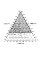
- FIG. 1 is a ternary composition diagram in which the alloy components deposited in the examples are plotted and shown together with the composition range of the Si—Sn—V-based alloy constituting the negative electrode active material for an electric device according to the embodiment of the present invention. is there.
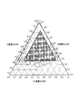
- FIG. 2 is a ternary composition diagram showing a preferable composition range of the Si—Sn—V-based alloy constituting the negative electrode active material for an electric device according to the embodiment of the present invention.
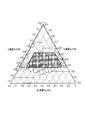
- FIG. 3 is a ternary composition diagram showing a more preferable composition range of the Si—Sn—V-based alloy constituting the negative electrode active material for an electric device according to the embodiment of the present invention.
- FIG. 1 is a ternary composition diagram in which the alloy components deposited in the examples are plotted and shown together with the composition range of the Si—Sn—V-based alloy constituting the negative electrode active material for an electric device according to the embodiment of the present invention. is there.
- FIG. 2 is a ternary composition diagram showing a preferable composition
- FIG. 4 is a ternary composition diagram showing a further preferable composition range of the Si—Sn—V-based alloy constituting the negative electrode active material for an electric device according to the embodiment of the present invention.
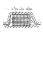
- FIG. 5 is a schematic cross-sectional view showing an example of a lithium ion secondary battery according to an embodiment of the present invention.
- the negative electrode active material for an electric device of the present invention will be described in detail by taking a negative electrode for a lithium ion secondary battery and a lithium ion secondary battery using the same as an example.
- “%” represents mass percentage unless otherwise specified.
- the dimensional proportions of the drawings are exaggerated for the convenience of the description, and may differ from the actual proportions.
- the negative electrode active material for an electric device of the present invention has a Si content of 27% by mass or more and less than 100% by mass, Sn of more than 0% by mass and 73% by mass or less, and V of more than 0% by mass and 73% by mass or less. And an alloy whose remainder is an unavoidable impurity. This numerical range corresponds to the range shown by the shaded portion in FIG.
- Such a negative electrode active material is used for an electric device, for example, a negative electrode of a lithium ion secondary battery.
- the alloy contained in the negative electrode active material absorbs lithium ions at the time of charge of the battery, and releases lithium ions at the time of discharge.
- the negative electrode active material contains a proper amount of a first additional element Sn and a second additional element V, which suppress the phase transition between amorphous and crystalline to improve the cycle life.
- the Si-Sn-V alloy negative electrode active material of the present invention not only exhibits high capacity, but also 50 cycles. After that, maintain high discharge capacity even after 100 cycles. That is, it becomes a Si-Sn-V alloy negative electrode active material having a good cycle life.
- the negative electrode active material of the present invention made of a Si-Sn-V alloy, when the content of at least one of Sn and V exceeds 73%, the Si content is less than 27%, so the initial discharge capacity Tend to decrease. Moreover, when it does not contain Sn and V, it exists in the tendency which does not show a favorable cycle life.
- the content of Si is 27 to 84%
- the content of Sn is 10 to 73%
- the content of V is 6 to 73%.
- the Si content is 27 to 84%
- the Sn content is 10 to 63%
- the V content is 6 to 63, as indicated by the shaded portions in FIG.
- the Si content is further in the range of 27 to 52%.
- the Sn content be in the range of 10 to 52%
- the V content be in the range of 20 to 63%.
- the Sn content is 10 to 40% by mass Range
- the negative electrode active material of the present invention can not avoid the inclusion of impurities derived from the raw material and the manufacturing method in addition to the above three components.
- the content of such unavoidable impurities is preferably less than 0.5% by mass, and more preferably less than 0.1% by mass.
- the alloy contained in the negative electrode active material of the present embodiment is 27% by mass or more and less than 100% by mass Si, more than 0% by mass and less than 73% by mass Sn, and more than 0% by mass It is an alloy containing V of less than 73% by mass and the balance being an unavoidable impurity. Therefore, in other words, the above alloy contains only 27% by mass to less than 100% by mass Si, more than 0% by mass and less than 73% by mass, V of more than 0% by mass and less than 73% by mass, and unavoidable impurities only It consists of
- the method for producing the negative electrode active material of the present invention that is, the Si-Sn-V-based alloy having the above-mentioned composition is not particularly limited, and the negative electrode active material can be produced using various known production methods. That is, since there is almost no difference in the alloy state or characteristics depending on the manufacturing method, any of the conventionally known manufacturing methods can be applied without any problem.
- a thin film alloy having the above composition is obtained by using a multi-component PVD method (sputtering method, resistance heating method, laser ablation method), a multi-component CVD method (chemical vapor deposition method) or the like.
- a multi-component PVD method sputtering method, resistance heating method, laser ablation method
- a multi-component CVD method chemical vapor deposition method
- the multiple PVD method a sputtering method, a resistance heating method, and a laser ablation method can be adopted.
- Chemical vapor deposition can be employed as the multiple CVD method.
- Such an alloy thin film can be used as a negative electrode by directly forming (film forming) on the current collector. Therefore, the method is excellent in that the process can be simplified and simplified.
- the alloy such as a binder and a conductive additive, which constitute the negative electrode active material layer, and the alloy thin film as the negative electrode active material can be used directly as the negative electrode. Therefore, it is excellent at the point which can aim at the high capacity
- a multiple DC magnetron sputtering apparatus can be used.
- an independently controlled ternary DC magnetron sputtering apparatus is employed.
- Si—Sn—V alloy thin films of various alloy compositions and thicknesses can be freely formed on the surface of the substrate (current collector).
- a target 1 (Si), a target 2 (Sn), and a target 3 (V) are used.
- the sputtering time is fixed, and for example, the power of the DC power supply is changed to Si: 185 W, Sn: 0 to 50 W, V: 0 to 150 W, respectively.
- the sputtering conditions are different for each sputtering apparatus, it is desirable to appropriately grasp the suitable range through preliminary experiments and the like for each sputtering apparatus.
- the thin film of the Si—Sn—V-based alloy can be used for the negative electrode active material layer of the present embodiment.
- the negative electrode active material layer can also be a layer containing particles of the above-described Si-Sn-V-based alloy as a main component.
- a mechanical alloy method, an arc plasma melting method, or the like can be used as a method for producing an alloy having the above-described composition in such a particle form.
- a slurry in which a binder, a conductive additive, a viscosity adjusting solvent, and the like are added to the alloy particles is prepared. Then, a negative electrode can be obtained by forming a negative electrode active material layer on the current collector using this slurry. Therefore, it is excellent in the point which is easy to mass-produce and easy to put it to practical use as a battery electrode.
- the average particle size thereof is not particularly limited as long as it is about the same as that of the conventional negative electrode active material.
- the thickness is preferably in the range of 1 to 20 ⁇ m.
- the above-mentioned effect can be effectively exhibited, it is not limited to such a range at all, and it may be out of the above range.
- particle diameter refers to an outline of active material particles (observation surface) observed using an observation means such as a scanning electron microscope (SEM) or a transmission electron microscope (TEM). Of the distances between any two points, it means the largest distance.
- SEM scanning electron microscope
- TEM transmission electron microscope
- the calculated value shall be adopted.
- the particle sizes and average particle sizes of other components can be defined in the same manner.
- the negative electrode for an electric device of the present invention uses a negative electrode active material composed of the above-mentioned Si-Sn-V alloy.
- a lithium ion secondary battery typical as an electric device has at least one unit cell provided with a negative electrode provided on the surface of the current collector with a negative electrode active material layer containing the above-mentioned negative electrode active material together with an electrolyte layer and a positive electrode. It is.
- the configuration of the above-described lithium ion secondary battery, the material thereof, and the like will be described below.
- FIG. 5 illustrates a lithium ion secondary battery according to an embodiment of the present invention.
- the lithium ion secondary battery 1 of the present embodiment has a configuration in which the battery element 10 to which the positive electrode tab 21 and the negative electrode tab 22 are attached is enclosed in the inside of the exterior body 30.
- the positive electrode tab 21 and the negative electrode tab 22 are respectively derived
- the positive electrode tab and the negative electrode tab may be drawn out in the same direction from the inside to the outside of the outer package.
- Such a positive electrode tab and a negative electrode tab can be attached to a positive electrode current collector and a negative electrode current collector to be described later, for example, by ultrasonic welding or resistance welding.
- the positive electrode tab 21 and the negative electrode tab 22 are made of, for example, materials such as aluminum (Al), copper (Cu), titanium (Ti), nickel (Ni), stainless steel (SUS), and alloys of these. However, the materials are not limited to these, and conventionally known materials that can be used as tabs for lithium ion secondary batteries can be used.
- the positive electrode tab and the negative electrode tab may be made of the same material, or may be made of different materials. Also, as in the present embodiment, the separately prepared tab may be connected to a positive electrode current collector and a negative electrode current collector described later, and each positive electrode current collector and each negative electrode current collector described later are in a foil shape. In some cases, the tabs may be formed by extending each one.
- the said exterior body 30 is formed by the film-shaped exterior material from a viewpoint of size reduction and weight reduction, for example.
- the present invention is not limited to this, and it is possible to use one made of a conventionally known material that can be used for an exterior body for a lithium ion secondary battery.
- a polymer-metal composite laminate sheet excellent in thermal conductivity is used to efficiently transmit heat from the heat source of the automobile and rapidly heat the inside of the battery to the battery operating temperature. Is preferred.
- the battery element 10 in the lithium ion secondary battery 1 of the present embodiment has a configuration in which a plurality of unit cell layers 14 composed of the positive electrode 11, the electrolyte layer 13 and the negative electrode 12 are stacked.
- the positive electrode 11 has a configuration in which the positive electrode active material layer 11B is formed on both main surfaces of the positive electrode current collector 11A.
- the negative electrode 12 has a configuration in which the negative electrode active material layer 12B is formed on both main surfaces of the negative electrode current collector 12A.
- the lithium ion secondary battery 1 has a configuration in which the plurality of unit cell layers 14 are stacked and electrically connected in parallel.
- the negative electrode active material layer 12B is formed on only one side.
- the insulating layer which is not shown in figure may be provided in the outer periphery of the cell layer 14. As shown in FIG.
- Such an insulating layer is preferably formed on the outer periphery of the unit cell layer with a material capable of holding the electrolyte included in the electrolyte layer or the like and preventing the electrolyte from leaking.
- general purpose plastics such as polypropylene (PP), polyethylene (PE), polyurethane (PUR), polyamide resin (PA), polytetrafluoroethylene (PTFE), polyvinylidene fluoride (PVdF), polystyrene (PS), etc.
- PP polypropylene
- PE polyethylene
- PUR polyurethane
- PA polyamide resin
- PTFE polytetrafluoroethylene
- PVdF polyvinylidene fluoride
- PS polystyrene
- thermoplastic olefin rubber, silicone rubber, etc. can also be used.
- the positive electrode current collector 11A and the negative electrode current collector 12A are made of, for example, a conductive material such as foil or mesh aluminum, copper, stainless steel (SUS) or the like.
- a conductive material such as foil or mesh aluminum, copper, stainless steel (SUS) or the like.
- the present invention is not limited thereto, and conventionally known materials that can be used as a current collector for lithium ion secondary batteries can be used.
- the size of the current collector can be determined according to the use application of the battery. For example, if it is used for a large battery where high energy density is required, a large-area current collector is used.
- the thickness of the current collector is also not particularly limited.
- the thickness of the current collector is usually about 1 to 100 ⁇ m.
- the shape of the current collector is not particularly limited.
- a mesh shape expansion grid etc.
- a current collector foil in addition to the current collector foil, a mesh shape (expanded grid etc.) or the like can be used.
- a current collector foil In the battery element 10 shown in FIG. 5, in addition to the current collector foil, a mesh shape (expanded grid etc.) or the like can be used.
- the thin film alloy as the negative electrode active material is directly formed on the negative electrode current collector 12A by sputtering or the like, it is desirable to use a current collector foil.
- the material constituting the current collector there is no particular limitation on the material constituting the current collector.
- a metal, or a resin in which a conductive filler is added to a conductive polymer material or a nonconductive polymer material can be employed.
- the metal include aluminum, nickel, iron, stainless steel, titanium and copper.
- it may be a foil in which a metal surface is coated with aluminum.
- aluminum, stainless steel, copper and nickel are preferable from the viewpoint of electron conductivity, battery operation potential, adhesion of the negative electrode active material by sputtering to a current collector, and the like.
- examples of the conductive polymer material include polyaniline, polypyrrole, polythiophene, polyacetylene, polyparaphenylene, polyphenylene vinylene, polyacrylonitrile, polyoxadiazole and the like.
- Such a conductive polymer material has sufficient conductivity even without the addition of a conductive filler, and thus is advantageous in facilitating the manufacturing process or reducing the weight of the current collector.
- nonconductive polymer material for example, polyethylene (PE; high density polyethylene (HDPE), low density polyethylene (LDPE), etc.), polypropylene (PP), polyethylene terephthalate (PET), polyether nitrile (PEN), polyimide (PI), polyamideimide (PAI), polyamide (PA), polytetrafluoroethylene (PTFE), styrene-butadiene rubber (SBR), polyacrylonitrile (PAN), polymethyl acrylate (PMA), polymethyl methacrylate (PMMA) And polyvinyl chloride (PVC), polyvinylidene fluoride (PVdF), polystyrene (PS) and the like.
- PE polyethylene
- HDPE high density polyethylene
- LDPE low density polyethylene
- PP polypropylene
- PET polyethylene terephthalate
- PEN polyether nitrile
- PI polyimide
- PAI polyamideimide
- PA polyamide
- PTFE polytetrafluor
- a conductive filler can be added to the above-mentioned conductive polymer material or non-conductive polymer material as needed.
- a conductive filler is essential to impart conductivity to the resin.
- the conductive filler can be used without particular limitation as long as it is a substance having conductivity.
- metals, conductive carbon, etc. may be mentioned as materials excellent in conductivity, potential resistance or lithium ion blocking properties.
- the metal is not particularly limited, and includes at least one metal selected from the group consisting of Ni, Ti, Al, Cu, Pt, Fe, Cr, Sn, Zn, In, Sb and K or a metal thereof It is preferable to include an alloy or a metal oxide.
- the conductive carbon is not particularly limited, but is preferably acetylene black, Vulcan (registered trademark), Black Pearl (registered trademark), carbon nanofiber, ketjen black (registered trademark), carbon nanotube, carbon nanohorn, carbon It contains at least one selected from the group consisting of nanoballoons and fullerenes.
- the addition amount of the conductive filler is not particularly limited as long as it can impart sufficient conductivity to the current collector, and is generally about 5 to 35% by mass of the entire current collector.
- the present invention is not limited thereto, and conventionally known materials used as current collectors for lithium ion secondary batteries can be used.
- the positive electrode 11 is formed by forming a positive electrode active material layer 11B on one side or both sides of a positive electrode current collector 11A made of a conductive material such as aluminum foil, copper foil, nickel foil or stainless steel foil. Be done.
- the thickness of the positive electrode current collector is not particularly limited as described above, and in general, it is preferably about 1 to 30 ⁇ m.
- the positive electrode active material layer 11B contains, as a positive electrode active material, any one or two or more of positive electrode materials capable of inserting and extracting lithium, and as necessary, contains a conductive auxiliary agent and a binder. It may be The compounding ratio of the positive electrode active material, the conductive additive, and the binder in the positive electrode active material layer is not particularly limited.
- lithium-transition metal complex oxide lithium-transition metal phosphate compound, lithium-transition metal sulfate compound, solid solution type, ternary system, NiMn type, NiCo type, spinel Mn type, etc. are mentioned.
- lithium-transition metal composite oxides examples include LiMn 2 O 4 , LiCoO 2 , LiNiO 2 , Li (Ni, Mn, Co) O 2 , Li (Li, Ni, Mn, Co) O 2 , LiFePO 4 and the like. Can be mentioned. In addition, those in which part of the transition metal of these composite oxides is substituted by another element can be employed.
- xLiMO 2 ⁇ (1-x) Li 2 NO 3 (0 ⁇ x ⁇ 1, M is an average oxidation state of 3+, N is one or more transition metals having an average oxidation state of 4+), LiRO 2- LiMn 2 O 4 (R transition metal element such as Ni, Mn, Co, Fe, etc.) and the like.
- ternary systems include nickel-cobalt-manganese composite cathode materials and the like.
- LiMn 2 O 4 etc. are mentioned as spinel Mn type
- LiNi 0.5 Mn 1.5 O 4 etc. are mentioned as a NiMn type
- two or more positive electrode active materials may be used in combination. From the viewpoint of capacity and output characteristics, a lithium-transition metal complex oxide is suitably used as a positive electrode active material.
- the particle diameter of the positive electrode active material is not particularly limited, but in general, the finer the particle, the more desirable. Further, in consideration of the working efficiency and the ease of handling, the average particle diameter may be about 1 to 30 ⁇ m, more preferably about 5 to 20 ⁇ m. Of course, positive electrode active materials other than the above can also be employed. In the case where the optimum particle size is different in expressing the specific effect of each active material, it is sufficient to blend and use the optimum particle sizes in order to express each specific effect. That is, it is not necessary to make the particle sizes of all the active materials uniform.
- the binder is added for the purpose of binding the active materials or the active material and the current collector to maintain the electrode structure.
- a binder polyvinylidene fluoride (PVDF), polytetrafluoroethylene (PTFE), polyvinyl acetate, polyimide (PI), polyamide (PA), polyvinyl chloride (PVC), polymethyl acrylate (PMA), Thermosetting resins such as thermoplastic resins such as polymethyl methacrylate (PMMA), polyether nitrile (PEN), polyethylene (PE), polypropylene (PP) and polyacrylonitrile (PAN), epoxy resin, polyurethane resin, and urea resin And rubber-based materials such as styrene butadiene rubber (SBR) can be used.
- PVDF polyvinylidene fluoride
- PTFE polytetrafluoroethylene
- PI polyimide
- PA polyamide
- PVC polyvinyl chloride
- PMA polymethyl acrylate
- the conductive aid is also simply referred to as a conductive agent, and refers to a conductive additive blended to improve the conductivity.
- the conductive aid used in the present invention is not particularly limited, and conventionally known ones can be used.
- carbon materials such as carbon black such as acetylene black, graphite and carbon fiber can be mentioned.
- the negative electrode 12 is configured by forming the negative electrode active material layer 12B on one side or both sides of the negative electrode current collector 12A made of the above-described conductive material.
- the negative electrode active material layer 12B contains, as a negative electrode active material, any one or two or more negative electrode materials capable of inserting and extracting lithium, and in the case of the above-described positive electrode active material, as necessary.
- the same conductive support agent and binder may be included.
- the compounding ratio of the negative electrode active material, the conductive additive, and the binder in the negative electrode active material layer is not particularly limited.
- the lithium ion secondary battery which is the electric device of the present invention includes the negative electrode active material containing the Si-Sn-V based alloy having the above-described composition as an essential component.
- the negative electrode active material layer 12B according to the present embodiment may be a thin film made of the above-mentioned Si-Sn-V alloy.
- the negative electrode active material layer 12B may be formed of only the above-mentioned Si-Sn-V-based alloy, or in combination with a conventionally known negative electrode active material capable of reversibly absorbing and desorbing lithium described later. There is no problem.
- the negative electrode active material layer 12B may be a layer containing particles of the Si-Sn-V-based alloy as a main component.
- the negative electrode active material layer 12B may contain the above-described conductive aid or binder that can be contained in the positive electrode active material layer 11B.
- the “main component” refers to a component having a content of 50% by mass or more in the negative electrode active material layer 12B.
- the negative electrode active material used in combination for example, graphite (natural graphite, artificial graphite etc.) which is high crystalline carbon, low crystalline carbon (soft carbon, hard carbon), carbon black (ketjen black, acetylene black, etc.)
- graphite natural graphite, artificial graphite etc.
- soft carbon hard carbon
- carbon black ketjen black, acetylene black, etc.
- Examples include carbon materials such as channel black, lamp black, oil furnace black, thermal black, etc., fullerenes, carbon nanotubes, carbon nanofibers, carbon nanohorns, and carbon fibrils.
- a negative electrode active material Si, Ge, Sn, Pb, Al, In, Zn, H, Ca, Sr, Ba, Ru, Rh, Ir, Pd, Pt, Ag, Cd, Hg, Ga, Tl And C, N, Sb, Bi, O, S, Se, Te, Cl, etc.
- oxides include silicon monoxide (SiO), SiO x (0 ⁇ x ⁇ 2), tin dioxide (SnO 2 ), SnO x (0 ⁇ x ⁇ 2), SnSiO 3 and the like.
- carbides include silicon carbide (SiC).
- examples of the negative electrode active material include metal materials such as lithium metal, and lithium-transition metal complex oxides such as lithium-titanium complex oxide (lithium titanate: Li 4 Ti 5 O 12 ). These negative electrode active materials can be used alone or in the form of a mixture of two or more.
- a negative electrode active material layer may be formed by applying a slurry containing a conductive support agent and a binder together with the negative electrode active material on the surface of the negative electrode current collector. Further, as the negative electrode, it is also possible to use a thin film of a negative electrode active material alloy formed directly on the surface of the negative electrode current collector by a multi-component PVD method, a CVD method or the like.
- the positive electrode active material layer and the negative electrode active material layer are formed on one side or both sides of each current collector.
- the negative electrode active material layer may be formed on the other side.
- Such electrodes can be applied to bipolar batteries.
- the electrolyte layer 13 is a layer containing a non-aqueous electrolyte, and the non-aqueous electrolyte has a function as a carrier of lithium ions moving between the positive and negative electrodes at the time of charge and discharge.
- the thickness of the electrolyte layer 13 is preferably as thin as possible from the viewpoint of reducing the internal resistance, and is usually in the range of about 1 to 100 ⁇ m, preferably 5 to 50 ⁇ m.
- the non-aqueous electrolyte contained in the electrolyte layer 13 is not particularly limited as long as it can exhibit a function as a lithium ion carrier, and a liquid electrolyte or a polymer electrolyte can be used.
- the liquid electrolyte has a configuration in which a lithium salt (electrolyte salt) is dissolved in an organic solvent.
- organic solvent include ethylene carbonate (EC), propylene carbonate (PC), butylene carbonate (BC), vinylene carbonate (VC), dimethyl carbonate (DMC), diethyl carbonate (DEC), ethyl methyl carbonate (EMC), Carbonates such as methyl propyl carbonate (MPC) can be mentioned.
- the lithium salt Li (CF 3 SO 2) 2 N, Li (C 2 F 5 SO 2) 2 N, LiPF 6, LiBF 4, LiAsF 6, LiTaF 6, LiClO 4, LiCF 3 SO 3 , etc.
- a compound that can be added to the electrode active material layer can be used.
- the polymer electrolyte is classified into a gel polymer electrolyte containing an electrolyte (gel electrolyte) and an intrinsic polymer electrolyte not containing an electrolyte.
- the gel polymer electrolyte has a configuration in which the liquid electrolyte is injected into a matrix polymer (host polymer) preferably comprising an ion conductive polymer.
- host polymer preferably comprising an ion conductive polymer.
- the ion conductive polymer used as a matrix polymer is not particularly limited, and examples thereof include polyethylene oxide (PEO), polypropylene oxide (PPO), polyvinylidene fluoride (PVDF), polyvinylidene fluoride and hexafluoropropylene. (PVDF-HFP), polyethylene glycol (PEG), polyacrylonitrile (PAN), polymethyl methacrylate (PMMA), and copolymers of these, and the like.
- PEO polyethylene oxide
- PPO polypropylene oxide
- PVDF polyvinylidene fluoride
- PVDF-HFP polyethylene glycol
- PAN polyacrylonitrile
- PMMA polymethyl methacrylate
- the above-mentioned ion conductive polymer may be the same as or different from the ion conductive polymer used as an electrolyte in the active material layer, but is preferably the same.
- the type of the electrolytic solution, that is, the lithium salt and the organic solvent is not particularly limited, and an electrolyte salt such as the lithium salt and an organic solvent such as carbonates may be used.
- the intrinsic polymer electrolyte is obtained by dissolving a lithium salt in the above-mentioned matrix polymer, and does not contain an organic solvent. Therefore, by using an intrinsic polymer electrolyte as the electrolyte, there is no concern of liquid leakage from the battery, and the reliability of the battery is improved.
- a gel polymer electrolyte or a matrix polymer of an intrinsic polymer electrolyte can exhibit excellent mechanical strength by forming a crosslinked structure.
- a polymerization treatment may be performed on a polymerizable polymer (for example, PEO or PPO) for forming a polymer electrolyte, using an appropriate polymerization initiator.
- a polymerizable polymer for example, PEO or PPO
- thermal polymerization, ultraviolet polymerization, radiation polymerization, electron beam polymerization and the like can be used.
- the non-aqueous electrolyte contained in the electrolyte layer 13 may be a single one consisting of only one type, or a mixture of two or more types.
- the electrolyte layer 13 is composed of a liquid electrolyte or a gel polymer electrolyte, it is preferable to use a separator for the electrolyte layer 13.
- a separator the microporous film which consists of polyolefins, such as polyethylene and a polypropylene, is mentioned, for example.
- the lithium ion secondary battery has a structure in which the battery element is housed in a battery case such as a can or a laminate container (package).
- the battery element (electrode assembly) is configured by connecting a positive electrode and a negative electrode via an electrolyte layer.
- the battery element is roughly classified into a wound type battery having a structure in which a positive electrode, an electrolyte layer and a negative electrode are wound, and a stacked type battery in which a positive electrode, an electrolyte layer and a negative electrode are stacked. It has a type structure. Also, depending on the shape and structure of the battery case, it may be referred to as a so-called coin cell, button battery, laminate battery or the like.
- a three-component DC magnetron sputtering apparatus (a combinatorial sputtering coating apparatus manufactured by Daiwa Instruments Industry Co., Ltd., a gun-sample distance: about 100 mm) was used as a sputtering apparatus. Then, a thin film of a negative electrode active material alloy having each composition was formed on a current collector substrate made of nickel foil and having a thickness of 20 ⁇ m under the following conditions. Thus, 31 negative electrode samples were obtained.
- sample no. In 14 the DC power supply 1 (Si target) is 185 W, the DC power supply 2 (Sn target) is 25 W, and the DC power supply 3 (V target) is 140 W.
- the DC power supply 1 (Si target) is 185 W
- the DC power supply 2 (Sn target) is 30 W
- the DC power supply 3 (V target) is 0 W.
- sample no. In 29 the DC power supply 1 (Si target) is 185 W
- the DC power supply 2 (Sn target) is 0 W
- the DC power supply 3 (V target) is 80 W.
- the analysis of the obtained alloy thin film was performed by the following analysis method and analyzer.
- the above charge and discharge cycle was regarded as one cycle. This was repeated 100 times, and the discharge capacity retention rate for the first cycle was examined for the 50th cycle and the 100th cycle.
- the discharge capacity is the value calculated per weight of the alloy, and the “discharge capacity retention ratio (%)” in Table 1 is 50 or 100 with respect to the discharge capacity at the first cycle.
- the ratio of the discharge capacity at the cycle is shown, that is, (discharge capacity at 50th cycle or 100th cycle) / (discharge capacity at 1st cycle) ⁇ 100.
- the batteries of sample numbers 1 to 4, 6 to 7, and 10 to 16 according to the examples have an excellent balance between the 1st cycle discharge capacity, the 50th cycle discharge capacity maintenance rate, and the 100th cycle discharge capacity maintenance rate I found that. That is, it was found that the above balance is excellent when Si is 27% by mass or more and less than 100% by mass, Sn is more than 0% by mass and 73% by mass and V is more than 0% by mass and 73% by mass or less .
- the discharge capacity retention ratio of the first cycle is larger than that of the battery of the example. The drop was found to be significant.
- the lithium ion secondary battery was illustrated as an electric device in the said embodiment and Example, it is not limited to this, It is applicable also to the secondary battery of another type, and also a primary battery. . Moreover, it can apply not only to a battery but to a capacitor. That is, the negative electrode for an electrical device or the electrical device of the present invention only needs to contain a predetermined alloy as a negative electrode active material, and the other constituent requirements are not particularly limited.
- the present invention can be applied not only to the above-described laminate type battery but also to a button type battery and a can type battery. Furthermore, the present invention can be applied not only to the above-described stacked (flat) battery but also to a wound (cylindrical) battery and the like.
- the present invention is not limited to the internal parallel connection type battery described above, but also to the internal serial connection type battery such as a bipolar battery, when viewed in an electrical connection state in a lithium ion secondary battery. It can apply.
- the battery element in the bipolar battery generally has a bipolar electrode in which a negative electrode active material layer is formed on one surface of a current collector and a positive electrode active material layer is formed on the other surface, an electrolyte layer, and Has a stacked structure.
- a silicon alloy containing Si, Sn, and V in the above composition range was used as the negative electrode active material for an electric device.
- the cycle life in an electric device such as a lithium ion secondary battery can be improved, and the capacity and the cycle durability can be excellent.
Abstract
Description
本発明の実施形態に係るリチウムイオン二次電池用負極活物質について詳細に説明する。 [Anode active material for electric devices]
The negative electrode active material for a lithium ion secondary battery according to the embodiment of the present invention will be described in detail.
本発明の電気デバイス用負極は、上記Si-Sn-V系合金から成る負極活物質を用いたものである。そして、電気デバイスとして代表的なリチウムイオン二次電池は、上記負極活物質を含む負極活物質層を集電体表面に備えた負極を電解質層及び正極と共に備えた少なくとも1つの単電池を有するものである。以下に、上記したリチウムイオン二次電池の構成やその材料などについてそれぞれ説明する。 [Anode for Electric Device and Electric Device]
The negative electrode for an electric device of the present invention uses a negative electrode active material composed of the above-mentioned Si-Sn-V alloy. And a lithium ion secondary battery typical as an electric device has at least one unit cell provided with a negative electrode provided on the surface of the current collector with a negative electrode active material layer containing the above-mentioned negative electrode active material together with an electrolyte layer and a positive electrode. It is. The configuration of the above-described lithium ion secondary battery, the material thereof, and the like will be described below.
図5に、本発明の一実施形態に係るリチウムイオン二次電池を例示する。図5に示すように、本実施形態のリチウムイオン二次電池1は、正極タブ21及び負極タブ22が取り付けられた電池要素10が外装体30の内部に封入された構成を有している。そして、本実施形態においては、正極タブ21及び負極タブ22が、外装体30の内部から外部に向かって、それぞれ反対の方向に導出されている。なお、図示しないが、正極タブ及び負極タブが、外装体の内部から外部に向かって、同一方向に導出される構成としてもよい。また、このような正極タブ及び負極タブは、例えば超音波溶接や抵抗溶接などにより後述する正極集電体及び負極集電体に取り付けることができる。 (Configuration of lithium ion secondary battery)
FIG. 5 illustrates a lithium ion secondary battery according to an embodiment of the present invention. As shown in FIG. 5, the lithium ion
上記正極タブ21及び負極タブ22は、例えば、アルミニウム(Al)や銅(Cu)、チタン(Ti)、ニッケル(Ni)、ステンレス鋼(SUS)、これらの合金などの材料により構成される。しかしながら、これらに限定されるものではなく、リチウムイオン二次電池用のタブとして用いることができる従来公知の材料を用いることができる。なお、正極タブ及び負極タブは、同一材質のものを用いてもよく、異なる材質のものを用いてもよい。また、本実施形態のように、別途準備したタブを後述する正極集電体及び負極集電体に接続してもよいし、後述する各正極集電体及び各負極集電体が箔状である場合は、それぞれを延長することによってタブを形成してもよい。 (Positive tab and negative tab)
The
上記外装体30は、例えば、小型化、軽量化の観点から、フィルム状の外装材で形成されたものであることが好ましい。ただし、これに限定されるものではなく、リチウムイオン二次電池用の外装体に使用可能な従来公知の材料で形成されたものを用いることができる。なお、自動車に適用する場合、自動車の熱源から効率よく熱を伝え、電池内部を迅速に電池動作温度まで加熱するために、例えば、熱伝導性に優れた高分子-金属複合ラミネートシートを用いることが好適である。 (Exterior body)
It is preferable that the said
図5に示すように、本実施形態のリチウムイオン二次電池1における電池要素10は、正極11と、電解質層13と、負極12とからなる単電池層14を複数積層した構成を有している。正極11は、正極集電体11Aの両方の主面上に正極活物質層11Bが形成された構成を有している。また、負極12は、負極集電体12Aの両方の主面上に負極活物質層12Bが形成された構成を有している。 (Battery element)
As shown in FIG. 5, the
正極集電体11A及び負極集電体12Aは、例えば、箔状又はメッシュ状のアルミニウム、銅、ステンレス(SUS)などの導電性の材料により構成される。しかしながら、これらに限定されるものではなく、リチウムイオン二次電池用の集電体として使用可能な従来公知の材料を用いることができる。また、集電体の大きさは、電池の使用用途に応じて決定することができる。例えば、高エネルギー密度が要求される大型の電池に用いられるのであれば、面積の大きな集電体が用いられる。集電体の厚さについても特に制限はない。集電体の厚さは、通常は1~100μm程度である。集電体の形状についても特に制限されない。図5に示す電池要素10では、集電箔のほか、網目形状(エキスパンドグリッド等)等を用いることができる。なお、スパッタ法等により、負極活物質たる薄膜合金を負極集電体12A上に直接形成する場合には、集電箔を用いるのが望ましい。 (Positive electrode current collector and negative electrode current collector)
The positive electrode
リチウムイオン二次電池において、正極11は、アルミニウム箔、銅箔、ニッケル箔、ステンレス箔などの導電性材料からなる正極集電体11Aの片面又は両面に、正極活物質層11Bが形成されて構成される。なお、正極集電体の厚さとしては、前述したように特に限定されず、一般には1~30μm程度であることが好ましい。 (Positive electrode)
In the lithium ion secondary battery, the
一方、負極12は、正極と同様に、上記したような導電性材料からなる負極集電体12Aの片面又は両面に、負極活物質層12Bが形成されて構成される。 (Negative electrode)
On the other hand, as in the case of the positive electrode, the
電解質層13は非水電解質を含む層であり、その非水電解質は充放電時に正負極間を移動するリチウムイオンのキャリアとしての機能を有する。なお、電解質層13の厚さとしては、内部抵抗を低減させる観点から薄いほどよく、通常1~100μm程度、好ましくは5~50μmの範囲とする。 (Electrolyte layer)
The
リチウムイオン二次電池は、電池素子を缶体やラミネート容器(包装体)などの電池ケースに収容した構造を有している。電池素子(電極構造体)は、正極と負極とが電解質層を介して接続されて構成されている。なお、電池素子が正極、電解質層及び負極を巻回した構造を有する巻回型の電池と、正極、電解質層及び負極を積層した積層型の電池に大別され、上述の双極型電池は積層型の構造を有する。また、電池ケースの形状や構造に応じて、いわゆるコインセル、ボタン電池、ラミネート電池などと称されることもある。 (Shape of battery)
The lithium ion secondary battery has a structure in which the battery element is housed in a battery case such as a can or a laminate container (package). The battery element (electrode assembly) is configured by connecting a positive electrode and a negative electrode via an electrolyte layer. The battery element is roughly classified into a wound type battery having a structure in which a positive electrode, an electrolyte layer and a negative electrode are wound, and a stacked type battery in which a positive electrode, an electrolyte layer and a negative electrode are stacked. It has a type structure. Also, depending on the shape and structure of the battery case, it may be referred to as a so-called coin cell, button battery, laminate battery or the like.
スパッタ装置として、独立制御方式の3元DCマグネトロンスパッタ装置(大和機器工業株式会社製、コンビナトリアルスパッタコーティング装置、ガン-サンプル間距離:約100mm)を使用した。そして、厚さ20μmのニッケル箔からなる集電体基板上に、以下の条件のもとで、各組成を有する負極活物質合金の薄膜をそれぞれ成膜した。このようにして、31種の負極サンプルを得た。 [1] Production of Negative Electrode A three-component DC magnetron sputtering apparatus (a combinatorial sputtering coating apparatus manufactured by Daiwa Instruments Industry Co., Ltd., a gun-sample distance: about 100 mm) was used as a sputtering apparatus. Then, a thin film of a negative electrode active material alloy having each composition was formed on a current collector substrate made of nickel foil and having a thickness of 20 μm under the following conditions. Thus, 31 negative electrode samples were obtained.
(1)ターゲット(株式会社高純度化学研究所製、純度:4N)
Si:50.8mm径、3mm厚さ(厚さ2mmの無酸素銅製バッキングプレート付)
Sn:50.8mm径、5mm厚さ
V:50.8mm径、5mm厚さ
(2)成膜条件
ベース圧力:~7×10⁻⁶
スパッタガス種:Ar(99.9999%以上)
スパッタガス導入量:10sccm
スパッタ圧力:30mTorr
DC電源:Si(185W)、Sn(0~50W)、V(0~150W)
プレスパッタ時間:1min.
スパッタ時間:10min.
基板温度:室温 (Preparation conditions)
(1) Target (manufactured by High Purity Chemical Laboratory Co., Ltd., Purity: 4 N)
Si: 50.8 mm diameter, 3 mm thickness (with 2 mm thick oxygen free copper backing plate)
Sn: 50.8 mm diameter, 5 mm thickness V: 50.8 mm diameter, 5 mm thickness (2) Film forming conditions Base pressure: ̃7 × 10 −6
Sputtering gas type: Ar (99.9999% or more)
Sputtering gas introduction amount: 10 sccm
Sputtering pressure: 30 mTorr
DC power supply: Si (185 W), Sn (0 to 50 W), V (0 to 150 W)
Pre-sputtering time: 1 min.
Sputtering time: 10 min.
Substrate temperature: room temperature
組成分析:SEM・EDX分析(JEOL社)、EPMA分析(JEOL社)
膜厚測定(スパッタレート算出のため):膜厚計(東京インスツルメンツ)
膜状態分析:ラマン分光測定(ブルカー社) (Analytical method)
Compositional analysis: SEM, EDX analysis (JEOL), EPMA analysis (JEOL)
Film thickness measurement (for sputter rate calculation): Film thickness meter (Tokyo Instruments)
Membrane state analysis: Raman spectroscopy (Bruker)
上述のようにして得られた各負極サンプルとリチウム箔から成る対極とをセパレータを介して対向させた後、電解液を注入することによってIEC60086に規定されたCR2032型コインセルをそれぞれ作製した。ここで、リチウム箔は本城金属株式会社製リチウムフォイルを使用し、直径15mm、厚さ200μmに打ち抜いたものを使用した。また、セパレータは、セルガード社製セルガード2400を使用した。なお、上記電解液としては、エチレンカーボネート(EC)とジエチルカーボネート(DEC)を1:1の容積比で混合した混合非水溶媒中に、LiPF6(六フッ化リン酸リチウム)を1Mの濃度となるように溶解させたものを用いた。 [2] Production of Battery After each negative electrode sample obtained as described above is made to face a counter electrode made of lithium foil through a separator, the CR2032 coin cell specified in IEC60086 is injected by injecting an electrolytic solution. Each was prepared. Here, lithium foil manufactured by Honjo Metal Co., Ltd. was used and was punched out to a diameter of 15 mm and a thickness of 200 μm. Moreover, the separator used Celgard 2400 made by Celgard. In the mixed nonaqueous solvent in which ethylene carbonate (EC) and diethyl carbonate (DEC) are mixed at a volume ratio of 1: 1, the concentration of 1 M of LiPF 6 (lithium hexafluorophosphate) is used as the electrolytic solution. What was dissolved so that it might be used was used.
上記のようにして得られたそれぞれの電池に対して、次の充放電試験を実施した。すなわち、充放電試験機を使用し、300K(27℃)の温度に設定された恒温槽(中にて、充電及び放電を行った。なお、充放電試験機としては、北斗電工株式会社製HJ0501SM8Aを使用し、恒温槽としては、エスペック株式会社製PFU-3Kを用いた。そして、充電過程、つまり評価対象である負極へのLi挿入過程では、定電流・定電圧モードとして、0.1mAにて2Vから10mVまで充電した。その後、放電過程、つまり上記負極からのLi脱離過程では、定電流モードとし、0.1mA、10mVから2Vまで放電した。以上の充放電サイクルを1サイクルとして、これを100回繰り返した。そして、1サイクル目に対する放電容量維持率を50サイクル目及び100サイクル目について調査した。この結果を表1に併せて示す。なお、放電容量は、合金重量当りで算出した値を示している。また、表1における「放電容量維持率(%)」とは、1サイクル目の放電容量に対する50又は100サイクル目の放電容量の割合を示す。すなわち、(50サイクル目又は100サイクル目の放電容量)/(1サイクル目の放電容量)×100で算出される。 [3] Charge / Discharge Test of Battery The following charge / discharge test was performed on each of the batteries obtained as described above. That is, using a charge / discharge tester, charging and discharging were carried out in a thermostatic chamber set at a temperature of 300 K (27 ° C.) As the charge / discharge tester, HJ0501SM8A manufactured by Hokuto Denko Co., Ltd. In the charging process, that is, the Li insertion process to the negative electrode to be evaluated, the constant current / constant voltage mode was set to 0.1 mA. After that, in the discharge process, that is, in the process of Li desorption from the negative electrode, constant current mode was set, and discharge was performed from 0.1 mV and 10 mV to 2 V. The above charge and discharge cycle was regarded as one cycle. This was repeated 100 times, and the discharge capacity retention rate for the first cycle was examined for the 50th cycle and the 100th cycle. The discharge capacity is the value calculated per weight of the alloy, and the “discharge capacity retention ratio (%)” in Table 1 is 50 or 100 with respect to the discharge capacity at the first cycle. The ratio of the discharge capacity at the cycle is shown, that is, (discharge capacity at 50th cycle or 100th cycle) / (discharge capacity at 1st cycle) × 100.

10 電池要素
11 正極
11A 正極集電体
11B 正極活物質層
12 負極
12A 負極集電体
12B 負極活物質層
13 電解質層
14 単電池層
21 正極タブ
22 負極タブ
30 外装体 DESCRIPTION OF
Claims (9)
- 27質量%以上100質量%未満のSiと、0質量%超73質量%以下のSnと、0質量%超73質量%以下のVを含有し、残部が不可避不純物である合金を有することを特徴とする電気デバイス用負極活物質。 It is characterized by containing an alloy containing 27% by mass or more and less than 100% by mass of Si, 0% by mass or more and 73% by mass or less Sn, and 0% by mass or more and 73% by mass or less of V, with the remainder being unavoidable impurities. Negative electrode active material for electrical devices.
- 前記合金が84質量%以下のSiと、10質量%以上73質量%以下のSnと、6質量%以上73質量%以下のVを含有することを特徴とする請求項1に記載の電気デバイス用負極活物質。 The electric alloy according to claim 1, wherein the alloy contains 84% by mass or less of Si, 10% by mass or more and 73% by mass or less Sn, and 6% by mass or more and 73% by mass or less of V. Negative electrode active material.
- 前記合金が、10質量%以上63質量%以下のSnと、6質量%以上63質量%以下のVを含有することを特徴とする請求項2に記載の電気デバイス用負極活物質。 The said alloy contains 10 mass% or more and 63 mass% or less Sn, and 6 mass% or more and 63 mass% or less V, The negative electrode active material for electric devices of Claim 2 characterized by the above-mentioned.
- 前記合金が52質量%以下のSiを含有することを特徴とする請求項3に記載の電気デバイス用負極活物質。 The said alloy contains 52 mass% or less of Si, The negative electrode active material for electric devices of Claim 3 characterized by the above-mentioned.
- 前記合金が40質量%以下のSnと、20質量%以上のVを含有することを特徴とする請求項4に記載の電気デバイス用負極活物質。 The said alloy contains 40 mass% or less Sn, and 20 mass% or more V, The negative electrode active material for electric devices of Claim 4 characterized by the above-mentioned.
- 請求項1~5のいずれか1つの項に記載の負極活物質を備えることを特徴とする電気デバイス用負極。 A negative electrode for an electric device comprising the negative electrode active material according to any one of claims 1 to 5.
- 請求項1~5のいずれか1つの項に記載の負極活物質を備えることを特徴とする電気デバイス。 An electric device comprising the negative electrode active material according to any one of claims 1 to 5.
- 請求項6に記載の電気デバイス用負極を備えることを特徴とする電気デバイス。 An electrical device comprising the negative electrode for an electrical device according to claim 6.
- リチウムイオン二次電池であることを特徴とする請求項7又は8に記載の電気デバイス。 The electric device according to claim 7, which is a lithium ion secondary battery.
Priority Applications (7)
| Application Number | Priority Date | Filing Date | Title |
|---|---|---|---|
| EP12789999.5A EP2717358B1 (en) | 2011-05-25 | 2012-03-09 | Negative electrode active material for electrical devices |
| US14/119,379 US10367198B2 (en) | 2011-05-25 | 2012-03-09 | Negative electrode active material for electric device |
| RU2013157562/07A RU2540321C1 (en) | 2011-05-25 | 2012-03-09 | Active material for negative electrode of electric device |
| MX2013013675A MX2013013675A (en) | 2011-05-25 | 2012-03-09 | Negative electrode active material for electrical devices. |
| KR1020137033924A KR101720832B1 (en) | 2011-05-25 | 2012-03-09 | Negative electrode active material for electric device |
| BR112013029744A BR112013029744A2 (en) | 2011-05-25 | 2012-03-09 | active material on negative electrode for fixtures |
| CN201280024983.1A CN103563134B (en) | 2011-05-25 | 2012-03-09 | Negative electrode active material for electrical |
Applications Claiming Priority (2)
| Application Number | Priority Date | Filing Date | Title |
|---|---|---|---|
| JP2011116536A JP5751448B2 (en) | 2011-05-25 | 2011-05-25 | Negative electrode active material for lithium ion secondary battery |
| JP2011-116536 | 2011-05-25 |
Publications (1)
| Publication Number | Publication Date |
|---|---|
| WO2012160858A1 true WO2012160858A1 (en) | 2012-11-29 |
Family
ID=47216947
Family Applications (1)
| Application Number | Title | Priority Date | Filing Date |
|---|---|---|---|
| PCT/JP2012/056128 WO2012160858A1 (en) | 2011-05-25 | 2012-03-09 | Negative electrode active material for electrical devices |
Country Status (11)
| Country | Link |
|---|---|
| US (1) | US10367198B2 (en) |
| EP (1) | EP2717358B1 (en) |
| JP (1) | JP5751448B2 (en) |
| KR (1) | KR101720832B1 (en) |
| CN (1) | CN103563134B (en) |
| BR (1) | BR112013029744A2 (en) |
| MX (1) | MX2013013675A (en) |
| MY (1) | MY158759A (en) |
| RU (1) | RU2540321C1 (en) |
| TW (1) | TWI473332B (en) |
| WO (1) | WO2012160858A1 (en) |
Cited By (9)
| Publication number | Priority date | Publication date | Assignee | Title |
|---|---|---|---|---|
| CN103280555A (en) * | 2013-01-21 | 2013-09-04 | 深圳大学 | Lithium ion battery silicon-based alloy cathode material and preparation method thereof and lithium ion battery |
| CN104798227A (en) * | 2012-11-22 | 2015-07-22 | 日产自动车株式会社 | Negative electrode for electrical device, and electrical device using same |
| EP2924775A4 (en) * | 2012-11-22 | 2015-12-09 | Nissan Motor | Negative electrode for electrical device, and electrical device using same |
| CN105934845A (en) * | 2014-01-24 | 2016-09-07 | 日产自动车株式会社 | Electrical device |
| US10290855B2 (en) | 2012-11-22 | 2019-05-14 | Nissan Motor Co., Ltd. | Negative electrode for electrical device, and electrical device using the same |
| US10367198B2 (en) | 2011-05-25 | 2019-07-30 | Nissan Motor Co., Ltd. | Negative electrode active material for electric device |
| US10476101B2 (en) | 2014-01-24 | 2019-11-12 | Nissan Motor Co., Ltd. | Electrical device |
| US10535870B2 (en) | 2014-01-24 | 2020-01-14 | Nissan Motor Co., Ltd. | Electrical device |
| US10566608B2 (en) | 2012-11-22 | 2020-02-18 | Nissan Motor Co., Ltd. | Negative electrode for electric device and electric device using the same |
Families Citing this family (2)
| Publication number | Priority date | Publication date | Assignee | Title |
|---|---|---|---|---|
| WO2016098211A1 (en) * | 2014-12-17 | 2016-06-23 | 日産自動車株式会社 | Negative-electrode active material for electric device, and electric device using same |
| NO20210413A1 (en) * | 2021-03-30 | 2022-10-03 | Elkem Materials | Ferrosilicon vanadium and/or niobium alloy, production of a ferrosilicon vanadium and/or niobium alloy, and the use thereof |
Citations (7)
| Publication number | Priority date | Publication date | Assignee | Title |
|---|---|---|---|---|
| JP2004185810A (en) * | 2001-11-20 | 2004-07-02 | Canon Inc | Electrode material for lithium secondary battery, electrode structural body with the electrode material, secondary battery with the electrode structure, manufacturing method of the electrode material, manufacturing method of the electrode structural body, and manufacturing method of the secondary battery |
| JP2005044672A (en) * | 2003-07-23 | 2005-02-17 | Mitsui Mining & Smelting Co Ltd | Negative electrode for nonaqueous electrolyte secondary battery and nonaqueous electrolyte secondary battery |
| JP2005078999A (en) * | 2003-09-02 | 2005-03-24 | Fukuda Metal Foil & Powder Co Ltd | Anode material for lithium secondary battery and its manufacturing method |
| JP2005116390A (en) * | 2003-10-09 | 2005-04-28 | Samsung Sdi Co Ltd | Electrode material for lithium secondary battery, lithium secondary battery, and manufacturing method of electrode material for lithium secondary battery |
| JP2006216277A (en) | 2005-02-01 | 2006-08-17 | Canon Inc | Method of manufacturing electrode material for lithium secondary battery, electrode structure, and secondary battery |
| WO2007015508A1 (en) * | 2005-08-02 | 2007-02-08 | Showa Denko K.K. | Alloy for negative electrode of lithium secondary battery |
| JP2009032644A (en) * | 2007-06-26 | 2009-02-12 | Daido Steel Co Ltd | Negative electrode active material for lithium secondary battery, and lithium secondary battery |
Family Cites Families (71)
| Publication number | Priority date | Publication date | Assignee | Title |
|---|---|---|---|---|
| JP4029235B2 (en) | 1998-10-02 | 2008-01-09 | 大阪瓦斯株式会社 | Negative electrode for lithium secondary battery |
| CA2305837C (en) | 1999-04-14 | 2011-05-31 | Sony Corporation | Material for negative electrode and nonaqueous-electrolyte battery incorporating the same |
| JP2000299108A (en) | 1999-04-14 | 2000-10-24 | Sony Corp | Nonaqueous electrolyte battery |
| JP3733070B2 (en) | 1999-10-22 | 2006-01-11 | 三洋電機株式会社 | Electrode for lithium secondary battery and lithium secondary battery |
| JP3702224B2 (en) | 1999-10-22 | 2005-10-05 | 三洋電機株式会社 | Method for producing electrode for lithium secondary battery |
| KR100520872B1 (en) | 1999-10-22 | 2005-10-12 | 산요덴키가부시키가이샤 | Electrode for lithium cell and lithium secondary cell |
| CA2388013A1 (en) | 1999-10-22 | 2001-04-26 | Sanyo Electric Co., Ltd. | A rechargeable lithium battery and an electrode therefor |
| CN100372153C (en) | 1999-10-22 | 2008-02-27 | 三洋电机株式会社 | Electrode for lithium cell and lithium secondary cell |
| JP2002083594A (en) | 1999-10-22 | 2002-03-22 | Sanyo Electric Co Ltd | Electrode for lithium battery, lithium battery using it and lithium secondary battery |
| JP2001196052A (en) | 2000-01-12 | 2001-07-19 | Sony Corp | Negative electrode and nonaqueous electrolyte battery |
| US6699336B2 (en) | 2000-01-13 | 2004-03-02 | 3M Innovative Properties Company | Amorphous electrode compositions |
| US7898053B2 (en) | 2000-02-04 | 2011-03-01 | Daniel Luch | Substrate structures for integrated series connected photovoltaic arrays and process of manufacture of such arrays |
| JP3848065B2 (en) | 2000-08-08 | 2006-11-22 | キヤノン株式会社 | Image forming apparatus |
| JP3744462B2 (en) | 2002-05-08 | 2006-02-08 | ソニー株式会社 | Non-aqueous electrolyte battery |
| EP1536499B1 (en) | 2002-06-26 | 2012-02-29 | Sanyo Electric Co., Ltd. | Negative electrode for lithium secondary cell and lithium secondary cell |
| JP4385589B2 (en) | 2002-11-26 | 2009-12-16 | 昭和電工株式会社 | Negative electrode material and secondary battery using the same |
| US7674555B2 (en) | 2002-11-26 | 2010-03-09 | Showa Denko K.K. | Electrode material, and production method and use thereof |
| AU2003302519A1 (en) * | 2002-11-29 | 2004-06-23 | Mitsui Mining And Smelting Co., Ltd. | Negative electrode for non-aqueous electrolyte secondary cell and method for manufacture thereof, and non-aqueous electrolyte secondary cell |
| JP3750117B2 (en) | 2002-11-29 | 2006-03-01 | 三井金属鉱業株式会社 | Negative electrode for nonaqueous electrolyte secondary battery, method for producing the same, and nonaqueous electrolyte secondary battery |
| CN100365849C (en) * | 2002-11-29 | 2008-01-30 | 三井金属矿业株式会社 | Negative electrode for nonaqueous secondary battery, process of producing the negative electrode, and nonaqueous secondary battery |
| JP4046601B2 (en) | 2002-12-03 | 2008-02-13 | 大阪瓦斯株式会社 | Negative electrode material for lithium secondary battery and lithium secondary battery using the same |
| JP4464173B2 (en) | 2003-03-26 | 2010-05-19 | キヤノン株式会社 | Electrode material for lithium secondary battery, electrode structure having the electrode material, and secondary battery having the electrode structure |
| TWI254473B (en) | 2003-03-26 | 2006-05-01 | Canon Kk | Electrode material for lithium secondary battery, electrode structure comprising the electrode material and secondary battery comprising the electrode structure |
| CN101179126B (en) | 2003-03-26 | 2011-09-28 | 佳能株式会社 | Electrode material, electrode structure and secondary battery having the electrode structure |
| WO2004095612A1 (en) | 2003-04-23 | 2004-11-04 | Mitsui Mining & Smelting Co., Ltd. | Negative electrode for nonaqueous electrolyte secondary battery, method for manufacturing same and nonaqueous electrolyte secondary battery |
| US7479351B2 (en) | 2003-10-09 | 2009-01-20 | Samsung Sdi Co., Ltd. | Electrode material for a lithium secondary battery, lithium secondary battery, and preparation method for the electrode material for a lithium secondary battery |
| JP4625672B2 (en) * | 2003-10-30 | 2011-02-02 | 株式会社東芝 | Nonaqueous electrolyte secondary battery |
| KR100800968B1 (en) * | 2004-09-11 | 2008-02-05 | 주식회사 엘지화학 | Method for Improvement of Performance of Si Thin Film Anode for Lithium Rechargeable Battery |
| JP5076288B2 (en) | 2005-07-14 | 2012-11-21 | 日本電気株式会社 | Secondary battery negative electrode and secondary battery using the same |
| JP2007026926A (en) | 2005-07-19 | 2007-02-01 | Nec Corp | Negative electrode for secondary battery and secondary battery using the same |
| US20070048612A1 (en) * | 2005-08-02 | 2007-03-01 | Showa Denko K.K. | Alloy for negative electrode of lithium secondary battery |
| JP2007149604A (en) | 2005-11-30 | 2007-06-14 | Sanyo Electric Co Ltd | Negative electrode for lithium secondary battery and lithium secondary battery |
| WO2007064531A1 (en) | 2005-12-01 | 2007-06-07 | 3M Innovative Properties Company | Electrode compositions based on an amorphous alloy having a high silicon content |
| US7906238B2 (en) | 2005-12-23 | 2011-03-15 | 3M Innovative Properties Company | Silicon-containing alloys useful as electrodes for lithium-ion batteries |
| JP4654381B2 (en) * | 2006-03-31 | 2011-03-16 | 福田金属箔粉工業株式会社 | Negative electrode for lithium secondary battery and method for producing the same |
| JP2007305424A (en) | 2006-05-11 | 2007-11-22 | Sony Corp | Negative electrode active material, and battery using it |
| US7875388B2 (en) | 2007-02-06 | 2011-01-25 | 3M Innovative Properties Company | Electrodes including polyacrylate binders and methods of making and using the same |
| JP2010518581A (en) | 2007-02-06 | 2010-05-27 | スリーエム イノベイティブ プロパティズ カンパニー | ELECTRODE CONTAINING NOVEL BINDING AGENT AND METHOD FOR PRODUCING AND USING THE SAME |
| JP2009224239A (en) | 2008-03-18 | 2009-10-01 | Nissan Motor Co Ltd | Electrode for battery |
| JP5357565B2 (en) | 2008-05-27 | 2013-12-04 | 株式会社神戸製鋼所 | Negative electrode material for lithium ion secondary battery, manufacturing method thereof, and lithium ion secondary battery |
| US9012073B2 (en) | 2008-11-11 | 2015-04-21 | Envia Systems, Inc. | Composite compositions, negative electrodes with composite compositions and corresponding batteries |
| JP2010205609A (en) | 2009-03-04 | 2010-09-16 | Nissan Motor Co Ltd | Electrode and battery using this |
| CN102326284A (en) | 2009-03-24 | 2012-01-18 | 古河电气工业株式会社 | Lithium ion rechargeable battery, electrode for battery, and electrodeposited copper foil for electrode for battery |
| EP2239803A1 (en) | 2009-04-10 | 2010-10-13 | Saft Groupe Sa | Active material composition for the negative electrode of a lithium-ion accumulator. |
| US20100288077A1 (en) | 2009-05-14 | 2010-11-18 | 3M Innovative Properties Company | Method of making an alloy |
| WO2010150513A1 (en) | 2009-06-23 | 2010-12-29 | キヤノン株式会社 | Electrode structure and electricity storage device |
| JP2011048969A (en) | 2009-08-26 | 2011-03-10 | Toyobo Co Ltd | Negative electrode for lithium ion secondary battery and secondary battery using the same |
| WO2011065504A1 (en) | 2009-11-27 | 2011-06-03 | 日産自動車株式会社 | Si ALLOY NEGATIVE ELECTRODE ACTIVE MATERIAL FOR ELECTRICAL DEVICE |
| US8835052B2 (en) | 2009-11-27 | 2014-09-16 | Nissan Motor Co., Ltd. | Si alloy negative electrode active material for electric device |
| JP5128695B2 (en) | 2010-06-28 | 2013-01-23 | 古河電気工業株式会社 | Electrolytic copper foil, electrolytic copper foil for lithium ion secondary battery, electrode for lithium ion secondary battery using the electrolytic copper foil, lithium ion secondary battery using the electrode |
| JP5850611B2 (en) | 2010-11-17 | 2016-02-03 | 三井金属鉱業株式会社 | Copper foil for lithium ion secondary battery negative electrode current collector, lithium ion secondary battery negative electrode material, and lithium ion secondary battery negative electrode current collector selection method. |
| TWI466367B (en) | 2010-12-27 | 2014-12-21 | Furukawa Electric Co Ltd | A lithium ion secondary battery, an electrode for the secondary battery, an electrode for an electrolytic copper foil |
| KR20120090594A (en) | 2011-02-08 | 2012-08-17 | 삼성전자주식회사 | Method of fabricating polymer electrode and polymer actuator employing the polymer electrode |
| JP5614729B2 (en) | 2011-03-03 | 2014-10-29 | 日産自動車株式会社 | Positive electrode active material for lithium ion secondary battery, positive electrode for lithium ion secondary battery, and lithium ion secondary battery |
| JP5768968B2 (en) | 2011-03-08 | 2015-08-26 | 日産自動車株式会社 | Negative electrode active material for lithium ion secondary battery |
| JP5751448B2 (en) | 2011-05-25 | 2015-07-22 | 日産自動車株式会社 | Negative electrode active material for lithium ion secondary battery |
| JP5776931B2 (en) | 2011-05-25 | 2015-09-09 | 日産自動車株式会社 | Negative electrode active material for lithium ion secondary battery |
| JP5776888B2 (en) | 2011-05-25 | 2015-09-09 | 日産自動車株式会社 | Negative electrode active material for electrical devices |
| JP2014531737A (en) | 2011-10-10 | 2014-11-27 | スリーエム イノベイティブ プロパティズ カンパニー | Amorphous alloy negative electrode composition for lithium ion electrochemical cell |
| JP5904363B2 (en) | 2011-12-27 | 2016-04-13 | 日産自動車株式会社 | Negative electrode active material for electrical devices |
| JP5904364B2 (en) | 2011-12-27 | 2016-04-13 | 日産自動車株式会社 | Negative electrode active material for electrical devices |
| US20130202967A1 (en) | 2012-02-07 | 2013-08-08 | Jae-Hyuk Kim | Negative active material for rechargeable lithium battery and rechargeable lithium battery including same |
| EP2924776B1 (en) | 2012-11-22 | 2018-05-09 | Nissan Motor Co., Ltd | Negative electrode for electrical device, and electrical device using same |
| EP2924777B1 (en) | 2012-11-22 | 2018-08-22 | Nissan Motor Co., Ltd | Negative electrode for electrical device and electrical device provided with same |
| EP2924779B1 (en) | 2012-11-22 | 2019-06-19 | Nissan Motor Co., Ltd. | Negative electrode for electrical device, and electrical device using same |
| KR20150065816A (en) | 2012-11-22 | 2015-06-15 | 닛산 지도우샤 가부시키가이샤 | Negative electrode for electrical device and electrical device provided with same |
| CN104854735B (en) | 2012-11-22 | 2018-05-08 | 日产自动车株式会社 | Electrical equipment is with anode and uses its electrical equipment |
| KR20180030265A (en) | 2012-11-22 | 2018-03-21 | 닛산 지도우샤 가부시키가이샤 | Negative electrode for electric device and electric device using the same |
| KR101823214B1 (en) | 2012-11-22 | 2018-01-29 | 닛산 지도우샤 가부시키가이샤 | Negative electrode for electrical device and electrical device provided with same |
| CN104813514B (en) | 2012-11-22 | 2017-10-13 | 日产自动车株式会社 | Electrical equipment is with negative pole and uses its electrical equipment |
| EP2924780B1 (en) | 2012-11-22 | 2020-08-05 | Nissan Motor Co., Ltd | Negative electrode for electrical device and electrical device provided with same |
-
2011
- 2011-05-25 JP JP2011116536A patent/JP5751448B2/en active Active
-
2012
- 2012-03-09 RU RU2013157562/07A patent/RU2540321C1/en not_active IP Right Cessation
- 2012-03-09 KR KR1020137033924A patent/KR101720832B1/en active IP Right Grant
- 2012-03-09 EP EP12789999.5A patent/EP2717358B1/en active Active
- 2012-03-09 US US14/119,379 patent/US10367198B2/en active Active
- 2012-03-09 WO PCT/JP2012/056128 patent/WO2012160858A1/en active Application Filing
- 2012-03-09 MY MYPI2013004201A patent/MY158759A/en unknown
- 2012-03-09 MX MX2013013675A patent/MX2013013675A/en active IP Right Grant
- 2012-03-09 BR BR112013029744A patent/BR112013029744A2/en not_active IP Right Cessation
- 2012-03-09 CN CN201280024983.1A patent/CN103563134B/en active Active
- 2012-03-16 TW TW101109120A patent/TWI473332B/en not_active IP Right Cessation
Patent Citations (7)
| Publication number | Priority date | Publication date | Assignee | Title |
|---|---|---|---|---|
| JP2004185810A (en) * | 2001-11-20 | 2004-07-02 | Canon Inc | Electrode material for lithium secondary battery, electrode structural body with the electrode material, secondary battery with the electrode structure, manufacturing method of the electrode material, manufacturing method of the electrode structural body, and manufacturing method of the secondary battery |
| JP2005044672A (en) * | 2003-07-23 | 2005-02-17 | Mitsui Mining & Smelting Co Ltd | Negative electrode for nonaqueous electrolyte secondary battery and nonaqueous electrolyte secondary battery |
| JP2005078999A (en) * | 2003-09-02 | 2005-03-24 | Fukuda Metal Foil & Powder Co Ltd | Anode material for lithium secondary battery and its manufacturing method |
| JP2005116390A (en) * | 2003-10-09 | 2005-04-28 | Samsung Sdi Co Ltd | Electrode material for lithium secondary battery, lithium secondary battery, and manufacturing method of electrode material for lithium secondary battery |
| JP2006216277A (en) | 2005-02-01 | 2006-08-17 | Canon Inc | Method of manufacturing electrode material for lithium secondary battery, electrode structure, and secondary battery |
| WO2007015508A1 (en) * | 2005-08-02 | 2007-02-08 | Showa Denko K.K. | Alloy for negative electrode of lithium secondary battery |
| JP2009032644A (en) * | 2007-06-26 | 2009-02-12 | Daido Steel Co Ltd | Negative electrode active material for lithium secondary battery, and lithium secondary battery |
Non-Patent Citations (1)
| Title |
|---|
| See also references of EP2717358A4 * |
Cited By (11)
| Publication number | Priority date | Publication date | Assignee | Title |
|---|---|---|---|---|
| US10367198B2 (en) | 2011-05-25 | 2019-07-30 | Nissan Motor Co., Ltd. | Negative electrode active material for electric device |
| CN104798227A (en) * | 2012-11-22 | 2015-07-22 | 日产自动车株式会社 | Negative electrode for electrical device, and electrical device using same |
| EP2924775A4 (en) * | 2012-11-22 | 2015-12-09 | Nissan Motor | Negative electrode for electrical device, and electrical device using same |
| EP2924776A4 (en) * | 2012-11-22 | 2016-04-27 | Nissan Motor | Negative electrode for electrical device, and electrical device using same |
| US10290855B2 (en) | 2012-11-22 | 2019-05-14 | Nissan Motor Co., Ltd. | Negative electrode for electrical device, and electrical device using the same |
| US10566608B2 (en) | 2012-11-22 | 2020-02-18 | Nissan Motor Co., Ltd. | Negative electrode for electric device and electric device using the same |
| CN103280555A (en) * | 2013-01-21 | 2013-09-04 | 深圳大学 | Lithium ion battery silicon-based alloy cathode material and preparation method thereof and lithium ion battery |
| CN105934845A (en) * | 2014-01-24 | 2016-09-07 | 日产自动车株式会社 | Electrical device |
| CN105934845B (en) * | 2014-01-24 | 2019-07-05 | 日产自动车株式会社 | Electrical part |
| US10476101B2 (en) | 2014-01-24 | 2019-11-12 | Nissan Motor Co., Ltd. | Electrical device |
| US10535870B2 (en) | 2014-01-24 | 2020-01-14 | Nissan Motor Co., Ltd. | Electrical device |
Also Published As
| Publication number | Publication date |
|---|---|
| KR101720832B1 (en) | 2017-04-10 |
| JP2012248286A (en) | 2012-12-13 |
| RU2540321C1 (en) | 2015-02-10 |
| EP2717358A1 (en) | 2014-04-09 |
| CN103563134A (en) | 2014-02-05 |
| MY158759A (en) | 2016-11-15 |
| US20140099229A1 (en) | 2014-04-10 |
| EP2717358B1 (en) | 2015-09-09 |
| KR20140024429A (en) | 2014-02-28 |
| TW201251185A (en) | 2012-12-16 |
| TWI473332B (en) | 2015-02-11 |
| CN103563134B (en) | 2016-04-20 |
| MX2013013675A (en) | 2014-02-27 |
| BR112013029744A2 (en) | 2017-01-17 |
| US10367198B2 (en) | 2019-07-30 |
| EP2717358A4 (en) | 2014-12-10 |
| JP5751448B2 (en) | 2015-07-22 |
Similar Documents
| Publication | Publication Date | Title |
|---|---|---|
| EP2800176B1 (en) | Negative electrode active material for electrical device | |
| JP5768968B2 (en) | Negative electrode active material for lithium ion secondary battery | |
| WO2012121241A1 (en) | Negative electrode active material for electrical device, and electrical device | |
| WO2012160858A1 (en) | Negative electrode active material for electrical devices | |
| WO2012160866A1 (en) | Negative electrode active material for electrical devices | |
| JP5776931B2 (en) | Negative electrode active material for lithium ion secondary battery | |
| US10547053B2 (en) | Negative electrode active material for electric device, negative electrode for electric device and electric device | |
| JP5945903B2 (en) | Negative electrode active material for electrical devices | |
| JP5751449B2 (en) | Negative electrode active material for lithium ion secondary battery |
Legal Events
| Date | Code | Title | Description |
|---|---|---|---|
| WWE | Wipo information: entry into national phase |
Ref document number: 201280024983.1 Country of ref document: CN |
|
| 121 | Ep: the epo has been informed by wipo that ep was designated in this application |
Ref document number: 12789999 Country of ref document: EP Kind code of ref document: A1 |
|
| WWE | Wipo information: entry into national phase |
Ref document number: 2012789999 Country of ref document: EP |
|
| WWE | Wipo information: entry into national phase |
Ref document number: 14119379 Country of ref document: US |
|
| WWE | Wipo information: entry into national phase |
Ref document number: MX/A/2013/013675 Country of ref document: MX |
|
| NENP | Non-entry into the national phase |
Ref country code: DE |
|
| ENP | Entry into the national phase |
Ref document number: 20137033924 Country of ref document: KR Kind code of ref document: A |
|
| ENP | Entry into the national phase |
Ref document number: 2013157562 Country of ref document: RU Kind code of ref document: A |
|
| REG | Reference to national code |
Ref country code: BR Ref legal event code: B01A Ref document number: 112013029744 Country of ref document: BR |
|
| ENP | Entry into the national phase |
Ref document number: 112013029744 Country of ref document: BR Kind code of ref document: A2 Effective date: 20131119 |