JP2012248286A - Negative electrode active material for electric device - Google Patents
Negative electrode active material for electric device Download PDFInfo
- Publication number
- JP2012248286A JP2012248286A JP2011116536A JP2011116536A JP2012248286A JP 2012248286 A JP2012248286 A JP 2012248286A JP 2011116536 A JP2011116536 A JP 2011116536A JP 2011116536 A JP2011116536 A JP 2011116536A JP 2012248286 A JP2012248286 A JP 2012248286A
- Authority
- JP
- Japan
- Prior art keywords
- negative electrode
- active material
- electrode active
- mass
- electric device
- Prior art date
- Legal status (The legal status is an assumption and is not a legal conclusion. Google has not performed a legal analysis and makes no representation as to the accuracy of the status listed.)
- Granted
Links
Images


Classifications
-
- H—ELECTRICITY
- H01—ELECTRIC ELEMENTS
- H01M—PROCESSES OR MEANS, e.g. BATTERIES, FOR THE DIRECT CONVERSION OF CHEMICAL ENERGY INTO ELECTRICAL ENERGY
- H01M4/00—Electrodes
- H01M4/02—Electrodes composed of, or comprising, active material
- H01M4/36—Selection of substances as active materials, active masses, active liquids
- H01M4/38—Selection of substances as active materials, active masses, active liquids of elements or alloys
- H01M4/386—Silicon or alloys based on silicon
-
- C—CHEMISTRY; METALLURGY
- C22—METALLURGY; FERROUS OR NON-FERROUS ALLOYS; TREATMENT OF ALLOYS OR NON-FERROUS METALS
- C22C—ALLOYS
- C22C13/00—Alloys based on tin
-
- C—CHEMISTRY; METALLURGY
- C22—METALLURGY; FERROUS OR NON-FERROUS ALLOYS; TREATMENT OF ALLOYS OR NON-FERROUS METALS
- C22C—ALLOYS
- C22C27/00—Alloys based on rhenium or a refractory metal not mentioned in groups C22C14/00 or C22C16/00
- C22C27/02—Alloys based on vanadium, niobium, or tantalum
- C22C27/025—Alloys based on vanadium, niobium, or tantalum alloys based on vanadium
-
- C—CHEMISTRY; METALLURGY
- C22—METALLURGY; FERROUS OR NON-FERROUS ALLOYS; TREATMENT OF ALLOYS OR NON-FERROUS METALS
- C22C—ALLOYS
- C22C28/00—Alloys based on a metal not provided for in groups C22C5/00 - C22C27/00
-
- C—CHEMISTRY; METALLURGY
- C22—METALLURGY; FERROUS OR NON-FERROUS ALLOYS; TREATMENT OF ALLOYS OR NON-FERROUS METALS
- C22C—ALLOYS
- C22C30/00—Alloys containing less than 50% by weight of each constituent
-
- C—CHEMISTRY; METALLURGY
- C22—METALLURGY; FERROUS OR NON-FERROUS ALLOYS; TREATMENT OF ALLOYS OR NON-FERROUS METALS
- C22C—ALLOYS
- C22C30/00—Alloys containing less than 50% by weight of each constituent
- C22C30/04—Alloys containing less than 50% by weight of each constituent containing tin or lead
-
- H—ELECTRICITY
- H01—ELECTRIC ELEMENTS
- H01G—CAPACITORS; CAPACITORS, RECTIFIERS, DETECTORS, SWITCHING DEVICES OR LIGHT-SENSITIVE DEVICES, OF THE ELECTROLYTIC TYPE
- H01G11/00—Hybrid capacitors, i.e. capacitors having different positive and negative electrodes; Electric double-layer [EDL] capacitors; Processes for the manufacture thereof or of parts thereof
- H01G11/04—Hybrid capacitors
- H01G11/06—Hybrid capacitors with one of the electrodes allowing ions to be reversibly doped thereinto, e.g. lithium ion capacitors [LIC]
-
- H—ELECTRICITY
- H01—ELECTRIC ELEMENTS
- H01G—CAPACITORS; CAPACITORS, RECTIFIERS, DETECTORS, SWITCHING DEVICES OR LIGHT-SENSITIVE DEVICES, OF THE ELECTROLYTIC TYPE
- H01G11/00—Hybrid capacitors, i.e. capacitors having different positive and negative electrodes; Electric double-layer [EDL] capacitors; Processes for the manufacture thereof or of parts thereof
- H01G11/22—Electrodes
- H01G11/30—Electrodes characterised by their material
- H01G11/50—Electrodes characterised by their material specially adapted for lithium-ion capacitors, e.g. for lithium-doping or for intercalation
-
- H—ELECTRICITY
- H01—ELECTRIC ELEMENTS
- H01M—PROCESSES OR MEANS, e.g. BATTERIES, FOR THE DIRECT CONVERSION OF CHEMICAL ENERGY INTO ELECTRICAL ENERGY
- H01M4/00—Electrodes
- H01M4/02—Electrodes composed of, or comprising, active material
- H01M4/36—Selection of substances as active materials, active masses, active liquids
- H01M4/38—Selection of substances as active materials, active masses, active liquids of elements or alloys
- H01M4/387—Tin or alloys based on tin
-
- H—ELECTRICITY
- H01—ELECTRIC ELEMENTS
- H01M—PROCESSES OR MEANS, e.g. BATTERIES, FOR THE DIRECT CONVERSION OF CHEMICAL ENERGY INTO ELECTRICAL ENERGY
- H01M10/00—Secondary cells; Manufacture thereof
- H01M10/05—Accumulators with non-aqueous electrolyte
- H01M10/052—Li-accumulators
- H01M10/0525—Rocking-chair batteries, i.e. batteries with lithium insertion or intercalation in both electrodes; Lithium-ion batteries
-
- H—ELECTRICITY
- H01—ELECTRIC ELEMENTS
- H01M—PROCESSES OR MEANS, e.g. BATTERIES, FOR THE DIRECT CONVERSION OF CHEMICAL ENERGY INTO ELECTRICAL ENERGY
- H01M2220/00—Batteries for particular applications
- H01M2220/20—Batteries in motive systems, e.g. vehicle, ship, plane
-
- H—ELECTRICITY
- H01—ELECTRIC ELEMENTS
- H01M—PROCESSES OR MEANS, e.g. BATTERIES, FOR THE DIRECT CONVERSION OF CHEMICAL ENERGY INTO ELECTRICAL ENERGY
- H01M4/00—Electrodes
- H01M4/02—Electrodes composed of, or comprising, active material
- H01M4/04—Processes of manufacture in general
- H01M4/0402—Methods of deposition of the material
- H01M4/0421—Methods of deposition of the material involving vapour deposition
- H01M4/0423—Physical vapour deposition
- H01M4/0426—Sputtering
-
- H—ELECTRICITY
- H01—ELECTRIC ELEMENTS
- H01M—PROCESSES OR MEANS, e.g. BATTERIES, FOR THE DIRECT CONVERSION OF CHEMICAL ENERGY INTO ELECTRICAL ENERGY
- H01M4/00—Electrodes
- H01M4/02—Electrodes composed of, or comprising, active material
- H01M4/13—Electrodes for accumulators with non-aqueous electrolyte, e.g. for lithium-accumulators; Processes of manufacture thereof
- H01M4/134—Electrodes based on metals, Si or alloys
-
- H—ELECTRICITY
- H01—ELECTRIC ELEMENTS
- H01M—PROCESSES OR MEANS, e.g. BATTERIES, FOR THE DIRECT CONVERSION OF CHEMICAL ENERGY INTO ELECTRICAL ENERGY
- H01M4/00—Electrodes
- H01M4/02—Electrodes composed of, or comprising, active material
- H01M4/13—Electrodes for accumulators with non-aqueous electrolyte, e.g. for lithium-accumulators; Processes of manufacture thereof
- H01M4/139—Processes of manufacture
- H01M4/1395—Processes of manufacture of electrodes based on metals, Si or alloys
-
- Y—GENERAL TAGGING OF NEW TECHNOLOGICAL DEVELOPMENTS; GENERAL TAGGING OF CROSS-SECTIONAL TECHNOLOGIES SPANNING OVER SEVERAL SECTIONS OF THE IPC; TECHNICAL SUBJECTS COVERED BY FORMER USPC CROSS-REFERENCE ART COLLECTIONS [XRACs] AND DIGESTS
- Y02—TECHNOLOGIES OR APPLICATIONS FOR MITIGATION OR ADAPTATION AGAINST CLIMATE CHANGE
- Y02E—REDUCTION OF GREENHOUSE GAS [GHG] EMISSIONS, RELATED TO ENERGY GENERATION, TRANSMISSION OR DISTRIBUTION
- Y02E60/00—Enabling technologies; Technologies with a potential or indirect contribution to GHG emissions mitigation
- Y02E60/10—Energy storage using batteries
-
- Y—GENERAL TAGGING OF NEW TECHNOLOGICAL DEVELOPMENTS; GENERAL TAGGING OF CROSS-SECTIONAL TECHNOLOGIES SPANNING OVER SEVERAL SECTIONS OF THE IPC; TECHNICAL SUBJECTS COVERED BY FORMER USPC CROSS-REFERENCE ART COLLECTIONS [XRACs] AND DIGESTS
- Y02—TECHNOLOGIES OR APPLICATIONS FOR MITIGATION OR ADAPTATION AGAINST CLIMATE CHANGE
- Y02E—REDUCTION OF GREENHOUSE GAS [GHG] EMISSIONS, RELATED TO ENERGY GENERATION, TRANSMISSION OR DISTRIBUTION
- Y02E60/00—Enabling technologies; Technologies with a potential or indirect contribution to GHG emissions mitigation
- Y02E60/13—Energy storage using capacitors
-
- Y—GENERAL TAGGING OF NEW TECHNOLOGICAL DEVELOPMENTS; GENERAL TAGGING OF CROSS-SECTIONAL TECHNOLOGIES SPANNING OVER SEVERAL SECTIONS OF THE IPC; TECHNICAL SUBJECTS COVERED BY FORMER USPC CROSS-REFERENCE ART COLLECTIONS [XRACs] AND DIGESTS
- Y02—TECHNOLOGIES OR APPLICATIONS FOR MITIGATION OR ADAPTATION AGAINST CLIMATE CHANGE
- Y02T—CLIMATE CHANGE MITIGATION TECHNOLOGIES RELATED TO TRANSPORTATION
- Y02T10/00—Road transport of goods or passengers
- Y02T10/60—Other road transportation technologies with climate change mitigation effect
- Y02T10/70—Energy storage systems for electromobility, e.g. batteries
Abstract
Description
本発明は、例えば、電気自動車(EV)やハイブリッド電気自動車(HEV)などのモータ駆動用電源に好適に用いられる二次電池や、キャパシタ等に代表される電気デバイス用の負極活物質と、これを用いた負極、電気デバイス、さらにはリチウムイオン二次電池に関するものである。 The present invention relates to, for example, a secondary battery suitably used for a motor driving power source such as an electric vehicle (EV) or a hybrid electric vehicle (HEV), a negative electrode active material for an electric device represented by a capacitor, and the like. The present invention relates to a negative electrode, an electrical device, and a lithium ion secondary battery.
近年、大気汚染や地球温暖化への対策として、CO2排出量の低減に向けた種々の取り組みがなされており、自動車業界においては、電気自動車やハイブリッド電気自動車の導入によるCO2排出量の削減が期待されている。そして、これら車両のモータ駆動用電源として、高性能な二次電池の開発が進んでいる。
上記したようなモータ駆動用の二次電池としては、特に高容量であることやサイクル特性に優れていることが求められる。このため、各種二次電池の中でも、高い理論エネルギーを有するリチウムイオン二次電池が注目されている。
In recent years, various efforts have been made to reduce CO 2 emissions as a measure against air pollution and global warming. In the automobile industry, reduction of CO 2 emissions by introducing electric vehicles and hybrid electric vehicles. Is expected. As a power source for driving these vehicles, high performance secondary batteries are being developed.
The secondary battery for driving a motor as described above is required to have particularly high capacity and excellent cycle characteristics. For this reason, lithium ion secondary batteries having high theoretical energy are attracting attention among various secondary batteries.
このようなリチウムイオン二次電池におけるエネルギー密度を高めるためには、正極と負極の単位質量当たりに蓄えられる電気量を高める必要があり、このような要求を満たすためには、それぞれの活物質の選定が極めて重要なものとなる。 In order to increase the energy density in such a lithium ion secondary battery, it is necessary to increase the amount of electricity stored per unit mass of the positive electrode and the negative electrode. Selection is extremely important.
リチウムイオン二次電池の性能向上の提案として、例えば、特許文献1には、体積当たりの放電容量が大きく、しかも充放電サイクル特性の優れたリチウムイオン二次電池用電極材料の製造方法が開示されている。
すなわち、上記文献には、Siを主成分とする粉末を湿式メディアミルで粉砕して得られた所定の平均粒径と比表面積を有するSi微粒子と、Sn、Alなど所定の元素を含む金属粉末と、炭素粉末をボールミルで乾式粉砕して、所定の平均粒径と比表面積の複合粒子とする電極材料の製造方法が提案されている。さらに、このようにして得られた電極をリチウムイオン二次電池の負極として用いることが記載されている。
As a proposal for improving the performance of a lithium ion secondary battery, for example, Patent Document 1 discloses a method for producing an electrode material for a lithium ion secondary battery having a large discharge capacity per volume and excellent charge / discharge cycle characteristics. ing.
That is, in the above document, a metal powder containing Si fine particles having a predetermined average particle diameter and specific surface area obtained by pulverizing a powder containing Si as a main component with a wet media mill, and a predetermined element such as Sn or Al. In addition, a method for producing an electrode material in which carbon powder is dry-ground by a ball mill to form composite particles having a predetermined average particle diameter and specific surface area has been proposed. Further, it is described that the electrode thus obtained is used as a negative electrode of a lithium ion secondary battery.
しかしながら、上記特許文献1に記載の負極材料を用いたリチウムイオン二次電池においては、SiとLiが合金化する際、アモルファス状態から結晶状態へ転移し、大きな体積変化が生ずることから、電極のサイクル寿命が低下するという問題がある。また、このようなSi系活物質の場合、容量とサイクル耐久性とはトレードオフの関係にあり、高容量を保持しつつ耐久性を向上させることが課題となっていた。 However, in the lithium ion secondary battery using the negative electrode material described in Patent Document 1, when Si and Li are alloyed, the amorphous state transitions to the crystalline state, resulting in a large volume change. There is a problem that the cycle life is reduced. Further, in the case of such a Si-based active material, the capacity and the cycle durability are in a trade-off relationship, and it has been a problem to improve the durability while maintaining a high capacity.
本発明は、従来の負極材料における上記課題を解決すべくなされたものであって、その目的とするところは、アモルファス−結晶の相転移を抑えてサイクル寿命を向上させることができ、しかも高容量を有するリチウムイオン二次電池など、電気デバイス用の負極活物質を提供することにある。また、このような負極活物質を適用した負極、さらにはこれらを用いた電気デバイス、例えばリチウムイオン二次電池を提供することにある。 The present invention has been made to solve the above-mentioned problems in conventional negative electrode materials, and its object is to suppress the amorphous-crystal phase transition and improve the cycle life, and to achieve a high capacity. It is providing the negative electrode active material for electric devices, such as a lithium ion secondary battery which has this. Moreover, it is providing the negative electrode to which such a negative electrode active material was applied, and also an electric device using these, for example, a lithium ion secondary battery.
本発明者らは、上記目的を達成すべく鋭意検討を繰り返した結果、Siに添加すべき第1及び第2の添加元素として、Sn及びVを選択し、これらの組成範囲をそれぞれ最適化することによって、上記目的が達成できることを見出し、本発明を完成するに至った。 As a result of intensive studies to achieve the above object, the present inventors select Sn and V as the first and second additive elements to be added to Si, and optimize their composition ranges, respectively. As a result, the inventors have found that the above object can be achieved and have completed the present invention.
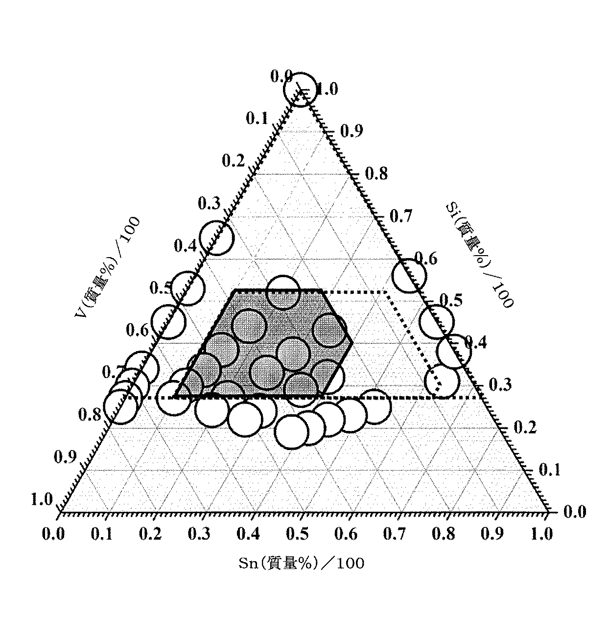
すなわち、本発明は上記知見に基づくものであって、本発明の電気デバイス用負極活物質は、27質量%以上のSi(ケイ素)と、73質量%以下のSn(錫)と、73質量%以下のV(バナジウム)を含有し、残部が不可避不純物である合金から成ることを特徴とする。 That is, this invention is based on the said knowledge, Comprising: The negative electrode active material for electrical devices of this invention is 27 mass% or more of Si (silicon), 73 mass% or less of Sn (tin), and 73 mass%. It is characterized by being made of an alloy containing the following V (vanadium) and the balance being inevitable impurities.
また、本発明の電気デバイス用負極は、本発明の上記負極活物質を集電体の表面に備えたことを特徴とし、本発明のリチウムイオン二次電池は、本発明の上記負極を備えたことを特徴としている。 The negative electrode for an electric device of the present invention is characterized in that the negative electrode active material of the present invention is provided on the surface of a current collector, and the lithium ion secondary battery of the present invention includes the negative electrode of the present invention. It is characterized by that.
本発明によれば、電気デバイス用負極活物質として、上記組成範囲のSi−Sn−V系3元合金を用いるようにしたため、このような負極活物質を用いた電気デバイス、例えばリチウムイオン二次電池に適用することによって、そのサイクル寿命を向上させ、容量及びサイクル耐久性に優れたものとすることができる。 According to the present invention, since the Si—Sn—V ternary alloy having the above composition range is used as the negative electrode active material for electric devices, an electric device using such a negative electrode active material, for example, a lithium ion secondary By applying to a battery, the cycle life can be improved and the capacity and cycle durability can be improved.
以下に、本発明の電気デバイス用負極活物質について、これを用いたリチウムイオン二次電池用負極やリチウムイオン二次電池を例として、詳細に説明する。なお、本明細書において、「%」は特記しない限り質量百分率を表すものとする。 Below, the negative electrode active material for electric devices of this invention is demonstrated in detail taking the negative electrode for lithium ion secondary batteries and lithium ion secondary battery using this as an example. In the present specification, “%” represents mass percentage unless otherwise specified.
本発明の電気デバイス用負極活物質は、上記したように、27%以上のSiと、73%以下(0は含まず)のSnと、73%以下(0は含まず)のVを含有し(図1参照)、残部が不可避不純物である合金から成るものであり、電気デバイス、例えばリチウムイオン二次電池の負極に用いられる。 As described above, the negative electrode active material for an electric device of the present invention contains 27% or more of Si, 73% or less (not including 0) of Sn, and 73% or less (not including 0) of V. (Refer to FIG. 1) The balance is made of an alloy whose inevitable impurities are used, and is used for a negative electrode of an electric device such as a lithium ion secondary battery.
すなわち、上記負極活物質は、第1添加元素であるSnと、第2添加元素であるVを適切に選択したことによって、Li合金化の際に、アモルファス−結晶の相転移を抑制してサイクル寿命を向上させることができる。また、これによって、炭素系負極活物質よりも高容量のものとなる。
そして、第1及び第2添加元素であるSnとVの組成範囲を最適化することにより、50サイクル後、100サイクル後も良好なサイクル寿命を備えたSi(Si−Sn−V系)合金負極活物質となる。
That is, the negative electrode active material is formed by appropriately selecting the first additive element Sn and the second additive element V, thereby suppressing the amorphous-crystal phase transition during Li alloying. Lifespan can be improved. Further, this makes the capacity higher than that of the carbon-based negative electrode active material.
Then, by optimizing the composition range of Sn and V as the first and second additive elements, a Si (Si—Sn—V) alloy negative electrode having a good cycle life after 50 cycles and after 100 cycles Become active material.
このとき、Si−Sn−V系合金から成る本発明の負極活物質においては、Sn及びVの一方又は両者の含有量が73%を超えると、Si含有量が27%に満たなくなって、初期放電容量が低下し、SnやVを含有しないと、良好なサイクル寿命を示さない。 At this time, in the negative electrode active material of the present invention made of the Si—Sn—V alloy, when the content of one or both of Sn and V exceeds 73%, the Si content becomes less than 27%, When the discharge capacity is reduced and Sn or V is not contained, good cycle life is not exhibited.
なお、当該負極活物質の上記特性をさらに良好なものとする観点からは、Si含有量については27〜84%、Sn含有量が10〜63%、V含有量が6〜63の範囲(図2参照)であることが好ましい。そして、さらにSi含有量が27〜52%の範囲(図3参照)、さらにSn含有量が10〜52%、V含有量が20〜63%の範囲(図4参照)であることが好ましい。 From the viewpoint of further improving the above characteristics of the negative electrode active material, the Si content is 27 to 84%, the Sn content is 10 to 63%, and the V content is 6 to 63 (see FIG. 2). Further, it is preferable that the Si content is in the range of 27 to 52% (see FIG. 3), the Sn content is in the range of 10 to 52%, and the V content is in the range of 20 to 63% (see FIG. 4).
また、本発明の負極活物質は、上記3成分の他に、原料や製法に由来する不純物の含有を避けることはできず、このような不可避不純物の含有量としては、0.5質量%未満であることが好ましく、0.1質量%未満であることがより好ましい。 In addition to the above three components, the negative electrode active material of the present invention cannot avoid the inclusion of impurities derived from raw materials and manufacturing methods. The content of such inevitable impurities is less than 0.5% by mass. And is more preferably less than 0.1% by mass.
本発明の負極活物質、すなわち上記組成のSi−Sn−V系合金の製造方法としては、特に制限されるものではなく、従来公知の各種の製造を利用して製造することができる。つまり、作製方法による合金状態や特性の違いはほとんどないことから、従来公知の作製方法をいずれも支障なく適用することができる。 The method for producing the negative electrode active material of the present invention, that is, the Si—Sn—V alloy having the above composition is not particularly limited, and can be produced by using various conventionally known production methods. That is, since there is almost no difference in alloy state and characteristics depending on the production method, any conventionally known production method can be applied without any problem.
具体的には、例えば、多元PVD法(スパッタ法、抵抗加熱法、レーザーアブレーション法)、多元CVD法(化学気相成長法)等を利用することによって、上記組成を有する薄膜形態の合金を得ることができる。
このような合金薄膜は、集電体上に直接形成(成膜)することによって負極電極とすることができ、工程の簡略化・簡素化が図れる点で優れている。さらには、合金(負極活物質)以外のバインダや導電助剤など、他の負極活物質層を構成する成分を用いる必要がなく、負極活物質としての合金薄膜をそのまま負極とすることができるため、車両用途の実用化レベルを満足する高容量及び高エネルギー密度化が図れる点で優れている。また、活物質の電気化学特性を調べるのに適している。
Specifically, for example, by using a multi-element PVD method (sputtering method, resistance heating method, laser ablation method), a multi-element CVD method (chemical vapor deposition method) or the like, an alloy in the form of a thin film having the above composition is obtained. be able to.
Such an alloy thin film can be used as a negative electrode by being directly formed (film formation) on a current collector, and is excellent in that the process can be simplified and simplified. Furthermore, it is not necessary to use other components constituting the negative electrode active material layer such as a binder or a conductive additive other than the alloy (negative electrode active material), and the alloy thin film as the negative electrode active material can be used as a negative electrode as it is. It is excellent in that it can achieve high capacity and high energy density that satisfy the practical application level of vehicle applications. It is also suitable for investigating the electrochemical characteristics of active materials.
上記した合金薄膜の製造に際しては、多元DCマグネトロンスパッタ装置として、例えば、独立制御の3元DCマグネトロンスパッタ装置を用いることによって、基板(集電体)表面に種々の合金組成及び厚さのSi−Sn−V系合金薄膜を自在に形成することができる。
例えば、ターゲット1(Si)、ターゲット2(Sn)、ターゲット3(V)を使用し、スパッタ時間を固定し、例えば、DC電源のパワーをそれぞれSi:185W、Sn:0〜50W、V:0〜150Wのようにそれぞれ変化させることによって、種々の組成式を有する3元系の合金サンプルを得ることができる。ただし、スパッタ条件はスパッタ装置ごとに違うため、スパッタ装置ごとに適宜、予備実験などを通じて好適な範囲を把握しておくことが望ましい。
When manufacturing the above-described alloy thin film, for example, by using an independently controlled ternary DC magnetron sputtering apparatus as a multi-element DC magnetron sputtering apparatus, Si— of various alloy compositions and thicknesses are formed on the surface of the substrate (current collector). Sn-V type alloy thin films can be freely formed.
For example, the target 1 (Si), the target 2 (Sn), and the target 3 (V) are used, and the sputtering time is fixed. For example, the power of the DC power source is Si: 185 W, Sn: 0 to 50 W, V: 0 By changing each to ˜150 W, ternary alloy samples having various composition formulas can be obtained. However, since the sputtering conditions are different for each sputtering apparatus, it is desirable to grasp a suitable range through preliminary experiments as appropriate for each sputtering apparatus.
一方、上記組成を有する粒子形態の合金の製造方法としては、例えば、メカニカルアロイ法、アークプラズマ溶融法等を利用することができる。
このような粒子形態の合金を負極活物質として使用する場合には、当該合金粒子にバインダ、導電助剤、粘度調整溶剤などを加えたスラリーを調整し、このスラリーを用いて集電体上に負極活物質層を形成することによって負極が得られる。したがって、量産化し易く、実際の電池用電極として実用化しやすい点で優れている。
On the other hand, for example, a mechanical alloy method, an arc plasma melting method, or the like can be used as a method for producing a particle-shaped alloy having the above composition.
When using such a particle-form alloy as a negative electrode active material, a slurry obtained by adding a binder, a conductive additive, a viscosity adjusting solvent, etc. to the alloy particles is prepared, and this slurry is used on the current collector. A negative electrode is obtained by forming a negative electrode active material layer. Therefore, it is excellent in that it is easily mass-produced and is easily put into practical use as an actual battery electrode.
なお、負極活物質として、粒子形態の合金を用いる場合には、その平均粒子径は、従来の負極活物質と同程度であれば、特に制限されることはない。但し、高出力化の観点からは、1〜20μmの範囲であることが好ましいが、上記した作用効果が有効に発現できるものであれば、上記範囲を外れていてもよいことは言うまでもない。 In addition, when using the alloy of a particle form as a negative electrode active material, the average particle diameter will not be restrict | limited especially if it is comparable as the conventional negative electrode active material. However, from the viewpoint of higher output, it is preferably in the range of 1 to 20 μm, but it goes without saying that it may be out of the above range as long as the above-described effects can be effectively expressed.
本発明の電気デバイス用負極は、上記Si−Sn−V系合金から成る負極活物質を用いたものであり、このような電気デバイスとして代表的なリチウムイオン二次電池は、上記負極活物質を含む負極活物質層を集電体表面に備えた負極を電解質層及び正極と共に備えた少なくとも1つの単電池を有するものである。
以下に、上記したリチウムイオン二次電池の構成やその材料などについてそれぞれ説明する。
The negative electrode for an electric device of the present invention uses a negative electrode active material composed of the Si-Sn-V alloy, and a typical lithium ion secondary battery as such an electric device includes the negative electrode active material. It has at least one unit cell provided with the negative electrode provided with the negative electrode active material layer which contains it on the collector surface, and the electrolyte layer and the positive electrode.
Hereinafter, the configuration and materials of the above-described lithium ion secondary battery will be described.
リチウムイオン二次電池は、一般に、正極集電体に正極活物質等を塗布した正極と、負極集電体に負極活物質等を塗布した負極とが、電解質層を介して接続され、電池ケース内に収納された構造を有している。 Generally, a lithium ion secondary battery has a battery case in which a positive electrode obtained by applying a positive electrode active material or the like to a positive electrode current collector and a negative electrode obtained by applying a negative electrode active material or the like to a negative electrode current collector are connected via an electrolyte layer. It has a structure housed inside.
〔正極〕
リチウムイオン二次電池において、正極は、アルミニウム箔、銅箔、ニッケル箔、ステンレス箔などの導電性材料から成る集電体(正極集電体)の片面又は両面に、正極活物質層、すなわち正極活物質と共に、必要に応じて導電助剤やバインダを含む正極活物質層を形成した構造を備えている。
[Positive electrode]
In a lithium ion secondary battery, the positive electrode is a positive electrode active material layer, that is, a positive electrode on one or both sides of a current collector (positive electrode current collector) made of a conductive material such as an aluminum foil, a copper foil, a nickel foil, or a stainless steel foil. A structure in which a positive electrode active material layer including a conductive additive and a binder is formed as necessary together with the active material is provided.
上記集電体の厚さとしては、特に限定されず、一般には1〜30μm程度であることが好ましい。また、正極活物質層中におけるこれら正極活物質、導電助剤、バインダの配合比としては、特に限定されない。 The thickness of the current collector is not particularly limited and is generally about 1 to 30 μm. Further, the mixing ratio of these positive electrode active material, conductive additive, and binder in the positive electrode active material layer is not particularly limited.
上記正極活物質としては、例えば、リチウム−遷移金属複合酸化物、リチウム−遷移金属リン酸化合物、リチウム−遷移金属硫酸化合物、固溶体系、3元系、NiMn系、NiCo系、スピネルMn系などが挙げられる。 Examples of the positive electrode active material include lithium-transition metal composite oxides, lithium-transition metal phosphate compounds, lithium-transition metal sulfate compounds, solid solution systems, ternary systems, NiMn systems, NiCo systems, and spinel Mn systems. Can be mentioned.
リチウム−遷移金属複合酸化物としては、例えば、LiMn2O4、LiCoO2、LiNiO2、Li(Ni、Mn、Co)O2、Li(Li、Ni、Mn、Co)O2、LiFePO4及びこれらの遷移金属の一部が他の元素により置換されたもの等を挙げることができる。
固溶体系としては、xLiMO2・(1−x)Li2NO3(0<x<1、Mは平均酸化状態が3+、Nは平均酸化状態が4+である1種類以上の遷移金属)、LiRO2−LiMn2O4(R=Ni、Mn、Co、Fe等の遷移金属元素)等が挙げられる。
Examples of the lithium-transition metal composite oxide include LiMn 2 O 4 , LiCoO 2 , LiNiO 2 , Li (Ni, Mn, Co) O 2 , Li (Li, Ni, Mn, Co) O 2 , LiFePO 4 and Examples thereof include those in which a part of these transition metals is substituted with other elements.
As a solid solution system, xLiMO 2 · (1-x) Li 2 NO 3 (0 <x <1, M is one or more transition metals having an average oxidation state of 3+ and N is an average oxidation state of 4+), LiRO 2- LiMn 2 O 4 (R = transition metal elements such as Ni, Mn, Co and Fe).
3元系としては、ニッケル・コバルト・マンガン系(複合)正極材等が挙げられる。スピネルMn系としてはLiMn2O4等が挙げられる。また、NiMn系としては、LiNi0.5Mn1.5O4等が挙げられる。NiCo系としては、Li(NiCo)O2等が挙げられる。
場合によっては、2種以上の正極活物質が併用されてもよい。好ましくは、容量、出力特性の観点から、リチウム−遷移金属複合酸化物が、正極活物質として用いられる。
Examples of the ternary system include nickel / cobalt / manganese (composite) positive electrode materials. Examples of the spinel Mn system include LiMn 2 O 4 . As the NiMn system include LiNi 0.5 Mn 1.5 O 4 and the like. Examples of the NiCo system include Li (NiCo) O 2 .
In some cases, two or more positive electrode active materials may be used in combination. Preferably, a lithium-transition metal composite oxide is used as the positive electrode active material from the viewpoint of capacity and output characteristics.
なお、上記正極活物質の粒径としては、特に限定するものではないが、一般には細かいほど望ましく、作業能率や取り扱いの容易さなどを考慮すると、平均粒径で、1〜30μm程度であればよく、5〜20μm程度であることがより好ましい。
また、上記以外の正極活物質が用いられてもよいことは言うまでもなく、活物質それぞれの固有の効果を発現する上で最適な粒径が異なる場合には、それぞれの固有の効果を発現する上で最適な粒径同士をブレンドして用いればよく、全ての活物質の粒径を必ずしも均一化させる必要はない。
In addition, although it does not specifically limit as a particle size of the said positive electrode active material, In general, it is so desirable that it is fine, and if the work efficiency, the ease of handling, etc. are considered, if it is about 1-30 micrometers in average particle diameter, It is more preferable that the thickness is about 5 to 20 μm.
In addition, it goes without saying that positive electrode active materials other than those described above may be used. When the optimum particle size is different for expressing the specific effect of each active material, The optimum particle diameters may be blended together and used, and it is not always necessary to make the particle diameters of all the active materials uniform.
上記バインダは、活物質同士又は活物質と集電体とを結着させて電極構造を維持する目的で添加される。
このようなバインダとしては、ポリフッ化ビニリデン(PVDF)、ポリテトラフルオロエチレン(PTFE)、ポリ酢酸ビニル、ポリイミド(PI)、ポリアミド(PA)、ポリ塩化ビニル(PVC)、ポリメチルアクリレート(PMA)、ポリメチルメタクリレート(PMMA)、ポリエーテルニトリル(PEN)、ポリエチレン(PE)、ポリプロピレン(PP)およびポリアクリロニトリル(PAN)などの熱可塑性樹脂、エポキシ樹脂、ポリウレタン樹脂、およびユリア樹脂などの熱硬化性樹脂、ならびにスチレンブタジエンゴム(SBR)などのゴム系材料を用いることができる。
The binder is added for the purpose of maintaining the electrode structure by binding the active materials or the active material and the current collector.
Examples of such a binder include polyvinylidene fluoride (PVDF), polytetrafluoroethylene (PTFE), polyvinyl acetate, polyimide (PI), polyamide (PA), polyvinyl chloride (PVC), polymethyl acrylate (PMA), Thermosetting resins such as polymethyl methacrylate (PMMA), polyether nitrile (PEN), polyethylene (PE), polypropylene (PP) and polyacrylonitrile (PAN), epoxy resins, polyurethane resins, and urea resins In addition, rubber-based materials such as styrene butadiene rubber (SBR) can be used.
導電助剤は、導電剤とも称し、導電性を向上させるために配合される導電性の添加物を意味する。本発明に使用する導電助剤としては、特に制限されず、従来公知のものを利用することができ、例えば、アセチレンブラック等のカーボンブラック、グラファイト、炭素繊維などの炭素材料を挙げることができる。
導電助剤を含有させることによって、活物質層の内部における電子ネットワークが効果的に形成され、電池の出力特性の向上、電解液の保液性の向上による信頼性向上に寄与する。
The conductive auxiliary agent is also referred to as a conductive agent, and means a conductive additive that is blended to improve conductivity. The conductive aid used in the present invention is not particularly limited, and conventionally known ones can be used, and examples thereof include carbon black such as acetylene black, and carbon materials such as graphite and carbon fiber.
By containing a conductive additive, an electronic network inside the active material layer is effectively formed, which contributes to improving the output characteristics of the battery and improving reliability by improving the liquid retention of the electrolytic solution.
〔負極〕
一方、負極は、正極と同様に、上記したような導電性材料から成る集電体(負極集電体)の片面又は両面に、負極活物質と共に、必要に応じて、上記した正極活物質の場合と同様の導電助剤やバインダを含有させて成る負極極活物質層を形成した構造を備えたものとすることができる。
[Negative electrode]
On the other hand, the negative electrode, like the positive electrode, is formed on one or both sides of a current collector (negative electrode current collector) made of the conductive material as described above together with the negative electrode active material, if necessary. It may have a structure in which a negative electrode active material layer formed by containing the same conductive additive or binder as in the case is formed.
本発明の電気デバイスであるリチウムイオン二次電池においては、上記した組成を備えたSi−Sn−V系合金から成る負極活物質が用いられるが、このような合金から成る負極活物質が必須成分として含有されてさえいれば、リチウムを可逆的に吸蔵及び放出できる従来公知の負極活物質を併用することに支障はない。
このような負極活物質としては、例えば、高結晶性カーボンであるグラファイト(天然グラファイト、人造グラファイト等),低結晶性カーボン(ソフトカーボン,ハードカーボン),カーボンブラック(ケッチェンブラック,アセチレンブラック,チャンネルブラック,ランプブラック,オイルファーネスブラック,サーマルブラック等),フラーレン,カーボンナノチューブ,カーボンナノファイバー,カーボンナノホーン,カーボンフィブリルなどの炭素材料、Si,Ge,Sn,Pb,Al,In,Zn,H,Ca,Sr,Ba,Ru,Rh,Ir,Pd,Pt,Ag,Au,Cd,Hg,Ga,Tl,C,N,Sb,Bi,O,S,Se,Te,Cl等のリチウムと合金化する元素の単体、及びこれらの元素を含む酸化物(一酸化ケイ素(SiO),SiOx(0<x<2),二酸化スズ(SnO2),SnOx(0<x<2),SnSiO3など)及び炭化物(炭化ケイ素(SiC)など)等、リチウム金属等の金属材料、リチウム−チタン複合酸化物(チタン酸リチウム:Li4Ti5O12)等のリチウム−遷移金属複合酸化物を挙げることができる。
In the lithium ion secondary battery which is the electrical device of the present invention, a negative electrode active material composed of a Si—Sn—V alloy having the above-described composition is used. A negative electrode active material composed of such an alloy is an essential component. As long as it is contained, there is no problem in using a conventionally known negative electrode active material capable of reversibly occluding and releasing lithium.
Examples of such negative electrode active materials include graphite (natural graphite, artificial graphite, etc.), which is highly crystalline carbon, low crystalline carbon (soft carbon, hard carbon), carbon black (Ketjen black, acetylene black, channel). Black, lamp black, oil furnace black, thermal black, etc.), fullerenes, carbon nanotubes, carbon nanofibers, carbon nanohorns, carbon fibrils and other carbon materials, Si, Ge, Sn, Pb, Al, In, Zn, H, Ca , Sr, Ba, Ru, Rh, Ir, Pd, Pt, Ag, Au, Cd, Hg, Ga, Tl, C, N, Sb, Bi, O, S, Se, Te, Cl, etc. are alloyed with lithium Elemental elements and oxides containing these elements (monoxide) Lee arsenide (SiO), SiOx (0 < x <2),
負極としては、上記したように、負極活物質と共に導電助剤やバインダを含むスラリーを集電体表面に塗布することによって負極極活物質層を形成したもののみならず、多元PVD法やCVD法等によって負極活物質合金の薄膜を集電体表面に直接成膜したものを用いることも可能である。 As described above, the negative electrode includes not only a negative electrode active material layer formed by applying a slurry containing a conductive additive or a binder together with a negative electrode active material to the current collector surface, but also a multi-element PVD method or a CVD method. It is also possible to use a negative electrode active material alloy thin film formed directly on the surface of the current collector by the above or the like.
なお、上記においては、正極活物質層及び負極活物質層をそれぞれの集電体の片面又は両面上に形成するものとして説明したが、1枚の集電体の一方の面に正極活物質層、他方の面に負極活物質層をそれぞれに形成することもでき、このような電極は、双極型電池に適用される。 In the above description, the positive electrode active material layer and the negative electrode active material layer are described as being formed on one or both surfaces of each current collector. However, the positive electrode active material layer is formed on one surface of one current collector. A negative electrode active material layer can be formed on the other surface, respectively, and such an electrode is applied to a bipolar battery.
〔電解質層〕
電解質層は、非水電解質を含む層であって、電解質層に含まれる非水電解質は、充放電時に正負極間を移動するリチウムイオンのキャリアーとしての機能を有する。
なお、電解質層の厚さとしては、内部抵抗を低減させる観点から薄ければ薄いほどよく、通常1〜100μm程度、好ましくは5〜50μmの範囲とする。
(Electrolyte layer)
The electrolyte layer is a layer containing a non-aqueous electrolyte, and the non-aqueous electrolyte contained in the electrolyte layer functions as a lithium ion carrier that moves between the positive and negative electrodes during charge and discharge.
The thickness of the electrolyte layer is preferably as thin as possible from the viewpoint of reducing internal resistance, and is usually in the range of about 1 to 100 μm, preferably 5 to 50 μm.
非水電解質としては、このような機能を発揮できるものであれば特に限定されず、液体電解質又はポリマー電解質を用いることができる。 The nonaqueous electrolyte is not particularly limited as long as it can exhibit such a function, and a liquid electrolyte or a polymer electrolyte can be used.
液体電解質は、有機溶媒にリチウム塩(電解質塩)が溶解した形態を有する。有機溶媒としては、例えば、エチレンカーボネート(EC)、プロピレンカーボネート(PC)、ブチレンカーボネート(BC)、ビニレンカーボネート(VC)、ジメチルカーボネート(DMC)、ジエチルカーボネート(DEC)、エチルメチルカーボネート(EMC)、メチルプロピルカーボネート(MPC)等のカーボネート類が例示される。
また、リチウム塩としては、Li(CF3SO2)2N、Li(C2F5SO2)2N、LiPF6、LiBF4、LiAsF6、LiTaF6、LiClO4、LiCF3SO3等の電極の活物質層に添加され得る化合物を採用することができる。
The liquid electrolyte has a form in which a lithium salt (electrolyte salt) is dissolved in an organic solvent. Examples of the organic solvent include ethylene carbonate (EC), propylene carbonate (PC), butylene carbonate (BC), vinylene carbonate (VC), dimethyl carbonate (DMC), diethyl carbonate (DEC), ethyl methyl carbonate (EMC), Examples include carbonates such as methylpropyl carbonate (MPC).
As the lithium salt, Li (CF 3 SO 2) 2 N, Li (C 2 F 5 SO 2) 2 N, LiPF 6, LiBF 4, LiAsF 6, LiTaF 6, LiClO 4, LiCF 3 SO 3 , etc. A compound that can be added to the active material layer of the electrode can be employed.
一方、ポリマー電解質は、電解液を含むゲルポリマー電解質(ゲル電解質)と、電解液を含まない真性ポリマー電解質に分類される。
ゲルポリマー電解質は、好ましくはイオン伝導性ポリマーからなるマトリックスポリマー(ホストポリマー)に、上記の液体電解質が注入されて成る構成を有する。電解質としてゲルポリマー電解質を用いることで電解質の流動性がなくなり、各層間のイオン伝導を遮断することが容易になる点で優れている。
On the other hand, the polymer electrolyte is classified into a gel polymer electrolyte containing an electrolytic solution (gel electrolyte) and an intrinsic polymer electrolyte containing no electrolytic solution.
The gel polymer electrolyte preferably has a structure in which the liquid electrolyte is injected into a matrix polymer (host polymer) made of an ion conductive polymer. The use of a gel polymer electrolyte as the electrolyte is superior in that the fluidity of the electrolyte is lost and it is easy to block ion conduction between the layers.
マトリックスポリマー(ホストポリマー)として用いられるイオン伝導性ポリマーとしては、特に限定されず、例えば、ポリエチレンオキシド(PEO)、ポリプロピレンオキシド(PPO)、ポリフッ化ビニリデン(PVDF)、ポリフッ化ビニリデンとヘキサフルオロプロピレンの共重合体(PVDF−HFP)、ポリエチレングリコール(PEG)、ポリアクリロニトリル(PAN)、ポリメチルメタクリレート(PMMA)及びこれらの共重合体等が挙げられる。
ここで、上記のイオン伝導性ポリマーは、活物質層において電解質として用いられるイオン伝導性ポリマーと同じであってもよく、異なっていてもよいが、同じであることが好ましい。電解液(リチウム塩及び有機溶媒)の種類は特に制限されず、上記で例示したリチウム塩などの電解質塩及びカーボネート類などの有機溶媒が用いられる。
The ion conductive polymer used as the matrix polymer (host polymer) is not particularly limited, and examples thereof include polyethylene oxide (PEO), polypropylene oxide (PPO), polyvinylidene fluoride (PVDF), polyvinylidene fluoride and hexafluoropropylene. Examples of the copolymer include PVDF-HFP, polyethylene glycol (PEG), polyacrylonitrile (PAN), polymethyl methacrylate (PMMA), and copolymers thereof.
Here, the ion conductive polymer may be the same as or different from the ion conductive polymer used as the electrolyte in the active material layer, but is preferably the same. The type of the electrolytic solution (lithium salt and organic solvent) is not particularly limited, and an electrolyte salt such as the lithium salt exemplified above and an organic solvent such as carbonates are used.
真性ポリマー電解質は、上記のマトリックスポリマーにリチウム塩が溶解して成るものであって、有機溶媒を含まない。したがって、電解質として真性ポリマー電解質を用いることによって電池からの液漏れの心配がなくなり、電池の信頼性が向上することになる。 The intrinsic polymer electrolyte is formed by dissolving a lithium salt in the above matrix polymer and does not contain an organic solvent. Therefore, by using an intrinsic polymer electrolyte as the electrolyte, there is no fear of liquid leakage from the battery, and the reliability of the battery is improved.
ゲルポリマー電解質や真性ポリマー電解質のマトリックスポリマーは、架橋構造を形成することによって、優れた機械的強度を発現することができる。このような架橋構造を形成させるには、適当な重合開始剤を用いて、高分子電解質形成用の重合性ポリマー(例えば、PEOやPPO)に対して熱重合、紫外線重合、放射線重合、電子線重合等の重合処理を施せばよい。
これらの電解質層に含まれる非水電解質は、1種のみから成る単独のものでも、2種以上を混合したものであっても差し支えない。
The matrix polymer of gel polymer electrolyte or intrinsic polymer electrolyte can express excellent mechanical strength by forming a crosslinked structure. In order to form such a crosslinked structure, thermal polymerization, ultraviolet polymerization, radiation polymerization, electron beam is applied to a polymerizable polymer (for example, PEO or PPO) for forming a polymer electrolyte, using an appropriate polymerization initiator. A polymerization process such as polymerization may be performed.
The non-aqueous electrolyte contained in these electrolyte layers may be a single type consisting of only one type or a mixture of two or more types.
なお、電解質層が液体電解質やゲルポリマー電解質から構成される場合には、電解質層にセパレータを用いる。
セパレータの具体的な形態としては、例えば、ポリエチレンやポリプロピレン等のポリオレフィンから成る微多孔膜が挙げられる。
In addition, when an electrolyte layer is comprised from a liquid electrolyte or a gel polymer electrolyte, a separator is used for the electrolyte layer.
Specific examples of the separator include a microporous film made of polyolefin such as polyethylene or polypropylene.
〔電池の形状〕
リチウムイオン二次電池は、上述のような正極と負極とが電解質層を介して接続された電池素子(電極構造体)を有しており、かかる電池素子を缶体やラミネート容器(包装体)などの電池ケースに収容した構造を有している。
なお、電池素子が正極、電解質層及び負極を巻回した構造を有する巻回型の電池と、正極、電解質層及び負極を積層型の電池に大別され、上述の双極型電池は積層型の構造を有する。また、電池ケースの形状や構造に応じて、いわゆるコインセル、ボタン電池、ラミネート電池などと称されることもある。
[Battery shape]
The lithium ion secondary battery has a battery element (electrode structure) in which the positive electrode and the negative electrode as described above are connected via an electrolyte layer, and the battery element can be used as a can or a laminate container (packaging body). It has a structure housed in a battery case.
The battery element is roughly divided into a wound battery having a structure in which a positive electrode, an electrolyte layer, and a negative electrode are wound, and a positive electrode, an electrolyte layer, and a negative electrode are stacked batteries, and the above bipolar battery is a stacked battery. It has a structure. Moreover, it may be called what is called a coin cell, a button battery, a laminate battery, etc. according to the shape and structure of a battery case.
以下、本発明を実施例に基づいて詳細に説明する。なお、本発明はこれら実施例に限定されるものではない。 Hereinafter, the present invention will be described in detail based on examples. The present invention is not limited to these examples.
〔1〕負極の作製
スパッタ装置として、独立制御方式の3元DCマグネトロンスパッタ装置(大和機器工業株式会社製、コンビナトリアルスパッタコーティング装置、ガン−サンプル間距離:約100mm)を使用し、厚さ20μmのニッケル箔から成る基板(集電体)上に、以下の条件のもとで、各組成を有する負極活物質合金の薄膜をそれぞれ成膜することによって、都合31種の負極サンプルを得た。
[1] Production of negative electrode As a sputtering apparatus, an independent control type three-way DC magnetron sputtering apparatus (Daiwa Kikai Kogyo Co., Ltd., combinatorial sputter coating apparatus, gun-sample distance: about 100 mm) is used. A negative electrode active material alloy thin film having each composition was formed on a substrate (current collector) made of nickel foil under the following conditions, thereby obtaining 31 types of negative electrode samples.
(1)ターゲット(株式会社高純度化学研究所製、純度:4N)
Si:50.8mm径、3mm厚さ(厚さ2mmの無酸素銅製バッキングプレート付)
Sn:50.8mm径、5mm厚さ
V:50.8mm径、5mm厚さ
(2)成膜条件
ベース圧力:〜7×10⁻⁶
スパッタガス種:Ar(99.9999%以上)
スパッタガス導入量:10sccm
スパッタ圧力:30mTorr
DC電源:Si(185W)、Sn(0〜50W)、V(0〜150W)
プレスパッタ時間:1min.
スパッタ時間:10min.
基板温度:室温
(1) Target (manufactured by Kojundo Chemical Laboratory Co., Ltd., purity: 4N)
Si: 50.8 mm diameter, 3 mm thickness (with 2 mm thick oxygen-free copper backing plate)
Sn: 50.8 mm diameter, 5 mm thickness V: 50.8 mm diameter, 5 mm thickness (2) Film formation conditions Base pressure: ~ 7 × 10 −6
Sputtering gas type: Ar (99.9999% or more)
Sputtering gas introduction amount: 10 sccm
Sputtering pressure: 30 mTorr
DC power supply: Si (185W), Sn (0-50W), V (0-150W)
Pre-sputtering time: 1 min.
Sputtering time: 10 min.
Substrate temperature: room temperature
すなわち、上記のようなSiターゲット、Snターゲット及びVターゲットを使用し、スパッタ時間は10分に固定し、DC電源のパワーを上記の範囲でそれぞれ変化させることによって、Ni基板上にアモルファス状態の合金薄膜を成膜し、種々の組成の合金薄膜を備えた負極サンプルを得た。これら合金薄膜の成分組成を表1及び図1に示す。
ここで、サンプル作製の数例を示せば、サンプルNo.14(実施例)では、DC電源1(Siターゲット):185W、DC電源2(Snターゲット):25W、DC電源3(Vターゲット):140Wとした。また、サンプルNo.23(比較例)では、DC電源1(Siターゲット):185W、DC電源2(Snターゲット):30W、DC電源3(Vターゲット):0Wとした。さらに、サンプルNo.29(比較例)では、DC電源1(Siターゲット):185W、DC電源2(Snターゲット):0W、DC電源3(Vターゲット):80Wとした。
That is, using the Si target, Sn target, and V target as described above, the sputtering time is fixed to 10 minutes, and the power of the DC power source is changed within the above range, whereby an amorphous alloy is formed on the Ni substrate. A thin film was formed, and negative electrode samples provided with alloy thin films having various compositions were obtained. The component compositions of these alloy thin films are shown in Table 1 and FIG.
Here, if several examples of sample preparation are shown, sample no. 14 (Example), DC power source 1 (Si target): 185 W, DC power source 2 (Sn target): 25 W, DC power source 3 (V target): 140 W. Sample No. 23 (comparative example), DC power source 1 (Si target): 185 W, DC power source 2 (Sn target): 30 W, DC power source 3 (V target): 0 W. Furthermore, sample no. In 29 (comparative example), DC power source 1 (Si target): 185 W, DC power source 2 (Sn target): 0 W, and DC power source 3 (V target): 80 W.
なお、得られた合金薄膜の分析は、下記の分析法、分析装置によった。 The obtained alloy thin film was analyzed by the following analysis method and analyzer.
(3)分析方法
組成分析:SEM・EDX分析(JEOL社)、EPMA分析(JEOL社)
膜厚測定(スパッタレート算出のため):膜厚計(東京インスツルメンツ)
膜状態分析:ラマン分光測定(ブルカー社)
(3) Analysis method Composition analysis: SEM / EDX analysis (JEOL), EPMA analysis (JEOL)
Film thickness measurement (for sputter rate calculation): Film thickness meter (Tokyo Instruments)
Film state analysis: Raman spectroscopy (Bruker)
〔2〕電池の作製
上記により得られた各負極サンプルとリチウム箔(本城金属株式会社製、直径15mm、厚さ200μm)から成る対極とをセパレータ(セルガード社製セルガード2400)を介して対向させたのち、電解液を注入することによってCR2032型コインセルをそれぞれ作製した。
なお、上記電解液としては、エチレンカーボネート(EC)とジエチルカーボネート(DEC)を1:1の容積比で混合した混合非水溶媒中に、LiPF6(六フッ化リン酸リチウム)を1Mの濃度となるように溶解させたものを用いた。
[2] Production of Battery Each negative electrode sample obtained above and a counter electrode made of lithium foil (Honjo Metal Co., Ltd., diameter 15 mm, thickness 200 μm) are opposed to each other through a separator (Celgard Cellguard 2400). Then, CR2032-type coin cells were produced by injecting an electrolyte solution.
As the above electrolyte solution, ethylene carbonate (EC) and diethyl carbonate (DEC) 1: in a mixed nonaqueous solvent were mixed at a volume ratio, the concentration of LiPF 6 a (lithium hexafluorophosphate) 1M What was dissolved so that it might become was used.
〔3〕電池の充放電試験
上記により得られたそれぞれの電池に対して以下の充放電試験を実施した。
すなわち、充放電試験機(北斗電工株式会社製HJ0501SM8A)を使用し、300K(27℃)の温度に設定された恒温槽(エスペック株式会社製PFU−3K)中にて、充電過程(評価対象である負極へのLi挿入過程)では、定電流・定電圧モードとして、0.1mAにて2Vから10mVまで充電した。その後、放電過程(上記負極からのLi脱離過程)では、定電流モードとし、0.1mA、10mVから2Vまで放電した。以上の充放電サイクルを1サイクルとして、これを100回繰り返した。
そして、1サイクル目に対する放電容量維持率を50サイクル目、及び100サイクル目について調査した。この結果を表1に併せて示す。なお、放電容量は、合金重量当りで算出した値を示している。
[3] Battery Charging / Discharging Test The following charging / discharging test was performed on each battery obtained as described above.
That is, using a charge / discharge tester (HJ0501SM8A manufactured by Hokuto Denko Co., Ltd.), in a thermostatic chamber (PFU-3K manufactured by Espec Co., Ltd.) set at a temperature of 300K (27 ° C), In a process of inserting Li into a certain negative electrode), the battery was charged from 2 V to 10 mV at 0.1 mA as a constant current / constant voltage mode. Thereafter, in the discharge process (Li desorption process from the negative electrode), the constant current mode was set, and discharge was performed from 0.1 mA, 10 mV to 2 V. The above charging / discharging cycle was made into 1 cycle, and this was repeated 100 times.
And the discharge capacity maintenance factor with respect to 1st cycle was investigated about 50th cycle and 100th cycle. The results are also shown in Table 1. The discharge capacity indicates a value calculated per alloy weight.
以上の結果、各成分が特定範囲内にあるSi−Sn−V系合金を負極活物質として用いた実施例電池においては、712mAh/g以上の初期容量と、50サイクル後では92%以上、100サイクル後では44%以上の放電容量維持率を示すことが確認された。 As a result, in the example battery using the Si—Sn—V alloy with each component in the specific range as the negative electrode active material, the initial capacity of 712 mAh / g or more, 92% or more after 50 cycles, 100% It was confirmed that the discharge capacity retention rate was 44% or more after the cycle.
Claims (7)
Priority Applications (11)
| Application Number | Priority Date | Filing Date | Title |
|---|---|---|---|
| JP2011116536A JP5751448B2 (en) | 2011-05-25 | 2011-05-25 | Negative electrode active material for lithium ion secondary battery |
| EP12789999.5A EP2717358B1 (en) | 2011-05-25 | 2012-03-09 | Negative electrode active material for electrical devices |
| US14/119,379 US10367198B2 (en) | 2011-05-25 | 2012-03-09 | Negative electrode active material for electric device |
| PCT/JP2012/056128 WO2012160858A1 (en) | 2011-05-25 | 2012-03-09 | Negative electrode active material for electrical devices |
| RU2013157562/07A RU2540321C1 (en) | 2011-05-25 | 2012-03-09 | Active material for negative electrode of electric device |
| MYPI2013004201A MY158759A (en) | 2011-05-25 | 2012-03-09 | Negative electrode active material for electric device |
| MX2013013675A MX2013013675A (en) | 2011-05-25 | 2012-03-09 | Negative electrode active material for electrical devices. |
| KR1020137033924A KR101720832B1 (en) | 2011-05-25 | 2012-03-09 | Negative electrode active material for electric device |
| BR112013029744A BR112013029744A2 (en) | 2011-05-25 | 2012-03-09 | active material on negative electrode for fixtures |
| CN201280024983.1A CN103563134B (en) | 2011-05-25 | 2012-03-09 | Negative electrode active material for electrical |
| TW101109120A TWI473332B (en) | 2011-05-25 | 2012-03-16 | Negative electrode active material for electrical equipment |
Applications Claiming Priority (1)
| Application Number | Priority Date | Filing Date | Title |
|---|---|---|---|
| JP2011116536A JP5751448B2 (en) | 2011-05-25 | 2011-05-25 | Negative electrode active material for lithium ion secondary battery |
Publications (2)
| Publication Number | Publication Date |
|---|---|
| JP2012248286A true JP2012248286A (en) | 2012-12-13 |
| JP5751448B2 JP5751448B2 (en) | 2015-07-22 |
Family
ID=47216947
Family Applications (1)
| Application Number | Title | Priority Date | Filing Date |
|---|---|---|---|
| JP2011116536A Active JP5751448B2 (en) | 2011-05-25 | 2011-05-25 | Negative electrode active material for lithium ion secondary battery |
Country Status (11)
| Country | Link |
|---|---|
| US (1) | US10367198B2 (en) |
| EP (1) | EP2717358B1 (en) |
| JP (1) | JP5751448B2 (en) |
| KR (1) | KR101720832B1 (en) |
| CN (1) | CN103563134B (en) |
| BR (1) | BR112013029744A2 (en) |
| MX (1) | MX2013013675A (en) |
| MY (1) | MY158759A (en) |
| RU (1) | RU2540321C1 (en) |
| TW (1) | TWI473332B (en) |
| WO (1) | WO2012160858A1 (en) |
Cited By (6)
| Publication number | Priority date | Publication date | Assignee | Title |
|---|---|---|---|---|
| EP2924775A4 (en) * | 2012-11-22 | 2015-12-09 | Nissan Motor | Negative electrode for electrical device, and electrical device using same |
| US20160285077A1 (en) * | 2012-11-22 | 2016-09-29 | Nissan Motor Co., Ltd. | Negative electrode for electric device and electric device using the same |
| US10290855B2 (en) | 2012-11-22 | 2019-05-14 | Nissan Motor Co., Ltd. | Negative electrode for electrical device, and electrical device using the same |
| US10367198B2 (en) | 2011-05-25 | 2019-07-30 | Nissan Motor Co., Ltd. | Negative electrode active material for electric device |
| US10476101B2 (en) | 2014-01-24 | 2019-11-12 | Nissan Motor Co., Ltd. | Electrical device |
| US10535870B2 (en) | 2014-01-24 | 2020-01-14 | Nissan Motor Co., Ltd. | Electrical device |
Families Citing this family (5)
| Publication number | Priority date | Publication date | Assignee | Title |
|---|---|---|---|---|
| EP2924776B1 (en) * | 2012-11-22 | 2018-05-09 | Nissan Motor Co., Ltd | Negative electrode for electrical device, and electrical device using same |
| CN103280555B (en) * | 2013-01-21 | 2015-10-21 | 深圳大学 | Silica-based alloy material of cathode of lithium ion battery and preparation method thereof and lithium ion battery |
| EP3098890B1 (en) * | 2014-01-24 | 2019-09-04 | Nissan Motor Co., Ltd | Electrical device |
| WO2016098211A1 (en) * | 2014-12-17 | 2016-06-23 | 日産自動車株式会社 | Negative-electrode active material for electric device, and electric device using same |
| NO20210413A1 (en) * | 2021-03-30 | 2022-10-03 | Elkem Materials | Ferrosilicon vanadium and/or niobium alloy, production of a ferrosilicon vanadium and/or niobium alloy, and the use thereof |
Citations (8)
| Publication number | Priority date | Publication date | Assignee | Title |
|---|---|---|---|---|
| JP2004185810A (en) * | 2001-11-20 | 2004-07-02 | Canon Inc | Electrode material for lithium secondary battery, electrode structural body with the electrode material, secondary battery with the electrode structure, manufacturing method of the electrode material, manufacturing method of the electrode structural body, and manufacturing method of the secondary battery |
| JP2005044672A (en) * | 2003-07-23 | 2005-02-17 | Mitsui Mining & Smelting Co Ltd | Negative electrode for nonaqueous electrolyte secondary battery and nonaqueous electrolyte secondary battery |
| JP2005078999A (en) * | 2003-09-02 | 2005-03-24 | Fukuda Metal Foil & Powder Co Ltd | Anode material for lithium secondary battery and its manufacturing method |
| JP2005116390A (en) * | 2003-10-09 | 2005-04-28 | Samsung Sdi Co Ltd | Electrode material for lithium secondary battery, lithium secondary battery, and manufacturing method of electrode material for lithium secondary battery |
| JP2006120324A (en) * | 2003-10-30 | 2006-05-11 | Toshiba Corp | Nonaqueous electrolyte secondary battery |
| WO2007015508A1 (en) * | 2005-08-02 | 2007-02-08 | Showa Denko K.K. | Alloy for negative electrode of lithium secondary battery |
| JP2007273355A (en) * | 2006-03-31 | 2007-10-18 | Fukuda Metal Foil & Powder Co Ltd | Negative electrode for lithium secondary battery, and its manufacturing method |
| JP2009032644A (en) * | 2007-06-26 | 2009-02-12 | Daido Steel Co Ltd | Negative electrode active material for lithium secondary battery, and lithium secondary battery |
Family Cites Families (70)
| Publication number | Priority date | Publication date | Assignee | Title |
|---|---|---|---|---|
| JP4029235B2 (en) | 1998-10-02 | 2008-01-09 | 大阪瓦斯株式会社 | Negative electrode for lithium secondary battery |
| CA2305837C (en) | 1999-04-14 | 2011-05-31 | Sony Corporation | Material for negative electrode and nonaqueous-electrolyte battery incorporating the same |
| JP2000299108A (en) | 1999-04-14 | 2000-10-24 | Sony Corp | Nonaqueous electrolyte battery |
| JP3733070B2 (en) | 1999-10-22 | 2006-01-11 | 三洋電機株式会社 | Electrode for lithium secondary battery and lithium secondary battery |
| JP3702224B2 (en) | 1999-10-22 | 2005-10-05 | 三洋電機株式会社 | Method for producing electrode for lithium secondary battery |
| KR100520872B1 (en) | 1999-10-22 | 2005-10-12 | 산요덴키가부시키가이샤 | Electrode for lithium cell and lithium secondary cell |
| CA2388013A1 (en) | 1999-10-22 | 2001-04-26 | Sanyo Electric Co., Ltd. | A rechargeable lithium battery and an electrode therefor |
| CN100372153C (en) | 1999-10-22 | 2008-02-27 | 三洋电机株式会社 | Electrode for lithium cell and lithium secondary cell |
| JP2002083594A (en) | 1999-10-22 | 2002-03-22 | Sanyo Electric Co Ltd | Electrode for lithium battery, lithium battery using it and lithium secondary battery |
| JP2001196052A (en) | 2000-01-12 | 2001-07-19 | Sony Corp | Negative electrode and nonaqueous electrolyte battery |
| US6699336B2 (en) | 2000-01-13 | 2004-03-02 | 3M Innovative Properties Company | Amorphous electrode compositions |
| US7898053B2 (en) | 2000-02-04 | 2011-03-01 | Daniel Luch | Substrate structures for integrated series connected photovoltaic arrays and process of manufacture of such arrays |
| JP3848065B2 (en) | 2000-08-08 | 2006-11-22 | キヤノン株式会社 | Image forming apparatus |
| JP3744462B2 (en) | 2002-05-08 | 2006-02-08 | ソニー株式会社 | Non-aqueous electrolyte battery |
| EP1536499B1 (en) | 2002-06-26 | 2012-02-29 | Sanyo Electric Co., Ltd. | Negative electrode for lithium secondary cell and lithium secondary cell |
| JP4385589B2 (en) | 2002-11-26 | 2009-12-16 | 昭和電工株式会社 | Negative electrode material and secondary battery using the same |
| US7674555B2 (en) | 2002-11-26 | 2010-03-09 | Showa Denko K.K. | Electrode material, and production method and use thereof |
| AU2003302519A1 (en) * | 2002-11-29 | 2004-06-23 | Mitsui Mining And Smelting Co., Ltd. | Negative electrode for non-aqueous electrolyte secondary cell and method for manufacture thereof, and non-aqueous electrolyte secondary cell |
| JP3750117B2 (en) | 2002-11-29 | 2006-03-01 | 三井金属鉱業株式会社 | Negative electrode for nonaqueous electrolyte secondary battery, method for producing the same, and nonaqueous electrolyte secondary battery |
| CN100365849C (en) * | 2002-11-29 | 2008-01-30 | 三井金属矿业株式会社 | Negative electrode for nonaqueous secondary battery, process of producing the negative electrode, and nonaqueous secondary battery |
| JP4046601B2 (en) | 2002-12-03 | 2008-02-13 | 大阪瓦斯株式会社 | Negative electrode material for lithium secondary battery and lithium secondary battery using the same |
| JP4464173B2 (en) | 2003-03-26 | 2010-05-19 | キヤノン株式会社 | Electrode material for lithium secondary battery, electrode structure having the electrode material, and secondary battery having the electrode structure |
| TWI254473B (en) | 2003-03-26 | 2006-05-01 | Canon Kk | Electrode material for lithium secondary battery, electrode structure comprising the electrode material and secondary battery comprising the electrode structure |
| CN101179126B (en) | 2003-03-26 | 2011-09-28 | 佳能株式会社 | Electrode material, electrode structure and secondary battery having the electrode structure |
| WO2004095612A1 (en) | 2003-04-23 | 2004-11-04 | Mitsui Mining & Smelting Co., Ltd. | Negative electrode for nonaqueous electrolyte secondary battery, method for manufacturing same and nonaqueous electrolyte secondary battery |
| US7479351B2 (en) | 2003-10-09 | 2009-01-20 | Samsung Sdi Co., Ltd. | Electrode material for a lithium secondary battery, lithium secondary battery, and preparation method for the electrode material for a lithium secondary battery |
| KR100800968B1 (en) * | 2004-09-11 | 2008-02-05 | 주식회사 엘지화학 | Method for Improvement of Performance of Si Thin Film Anode for Lithium Rechargeable Battery |
| JP2006216277A (en) | 2005-02-01 | 2006-08-17 | Canon Inc | Method of manufacturing electrode material for lithium secondary battery, electrode structure, and secondary battery |
| JP5076288B2 (en) | 2005-07-14 | 2012-11-21 | 日本電気株式会社 | Secondary battery negative electrode and secondary battery using the same |
| JP2007026926A (en) | 2005-07-19 | 2007-02-01 | Nec Corp | Negative electrode for secondary battery and secondary battery using the same |
| US20070048612A1 (en) * | 2005-08-02 | 2007-03-01 | Showa Denko K.K. | Alloy for negative electrode of lithium secondary battery |
| JP2007149604A (en) | 2005-11-30 | 2007-06-14 | Sanyo Electric Co Ltd | Negative electrode for lithium secondary battery and lithium secondary battery |
| WO2007064531A1 (en) | 2005-12-01 | 2007-06-07 | 3M Innovative Properties Company | Electrode compositions based on an amorphous alloy having a high silicon content |
| US7906238B2 (en) | 2005-12-23 | 2011-03-15 | 3M Innovative Properties Company | Silicon-containing alloys useful as electrodes for lithium-ion batteries |
| JP2007305424A (en) | 2006-05-11 | 2007-11-22 | Sony Corp | Negative electrode active material, and battery using it |
| US7875388B2 (en) | 2007-02-06 | 2011-01-25 | 3M Innovative Properties Company | Electrodes including polyacrylate binders and methods of making and using the same |
| JP2010518581A (en) | 2007-02-06 | 2010-05-27 | スリーエム イノベイティブ プロパティズ カンパニー | ELECTRODE CONTAINING NOVEL BINDING AGENT AND METHOD FOR PRODUCING AND USING THE SAME |
| JP2009224239A (en) | 2008-03-18 | 2009-10-01 | Nissan Motor Co Ltd | Electrode for battery |
| JP5357565B2 (en) | 2008-05-27 | 2013-12-04 | 株式会社神戸製鋼所 | Negative electrode material for lithium ion secondary battery, manufacturing method thereof, and lithium ion secondary battery |
| US9012073B2 (en) | 2008-11-11 | 2015-04-21 | Envia Systems, Inc. | Composite compositions, negative electrodes with composite compositions and corresponding batteries |
| JP2010205609A (en) | 2009-03-04 | 2010-09-16 | Nissan Motor Co Ltd | Electrode and battery using this |
| CN102326284A (en) | 2009-03-24 | 2012-01-18 | 古河电气工业株式会社 | Lithium ion rechargeable battery, electrode for battery, and electrodeposited copper foil for electrode for battery |
| EP2239803A1 (en) | 2009-04-10 | 2010-10-13 | Saft Groupe Sa | Active material composition for the negative electrode of a lithium-ion accumulator. |
| US20100288077A1 (en) | 2009-05-14 | 2010-11-18 | 3M Innovative Properties Company | Method of making an alloy |
| WO2010150513A1 (en) | 2009-06-23 | 2010-12-29 | キヤノン株式会社 | Electrode structure and electricity storage device |
| JP2011048969A (en) | 2009-08-26 | 2011-03-10 | Toyobo Co Ltd | Negative electrode for lithium ion secondary battery and secondary battery using the same |
| WO2011065504A1 (en) | 2009-11-27 | 2011-06-03 | 日産自動車株式会社 | Si ALLOY NEGATIVE ELECTRODE ACTIVE MATERIAL FOR ELECTRICAL DEVICE |
| US8835052B2 (en) | 2009-11-27 | 2014-09-16 | Nissan Motor Co., Ltd. | Si alloy negative electrode active material for electric device |
| JP5128695B2 (en) | 2010-06-28 | 2013-01-23 | 古河電気工業株式会社 | Electrolytic copper foil, electrolytic copper foil for lithium ion secondary battery, electrode for lithium ion secondary battery using the electrolytic copper foil, lithium ion secondary battery using the electrode |
| JP5850611B2 (en) | 2010-11-17 | 2016-02-03 | 三井金属鉱業株式会社 | Copper foil for lithium ion secondary battery negative electrode current collector, lithium ion secondary battery negative electrode material, and lithium ion secondary battery negative electrode current collector selection method. |
| TWI466367B (en) | 2010-12-27 | 2014-12-21 | Furukawa Electric Co Ltd | A lithium ion secondary battery, an electrode for the secondary battery, an electrode for an electrolytic copper foil |
| KR20120090594A (en) | 2011-02-08 | 2012-08-17 | 삼성전자주식회사 | Method of fabricating polymer electrode and polymer actuator employing the polymer electrode |
| JP5614729B2 (en) | 2011-03-03 | 2014-10-29 | 日産自動車株式会社 | Positive electrode active material for lithium ion secondary battery, positive electrode for lithium ion secondary battery, and lithium ion secondary battery |
| JP5768968B2 (en) | 2011-03-08 | 2015-08-26 | 日産自動車株式会社 | Negative electrode active material for lithium ion secondary battery |
| JP5751448B2 (en) | 2011-05-25 | 2015-07-22 | 日産自動車株式会社 | Negative electrode active material for lithium ion secondary battery |
| JP5776931B2 (en) | 2011-05-25 | 2015-09-09 | 日産自動車株式会社 | Negative electrode active material for lithium ion secondary battery |
| JP5776888B2 (en) | 2011-05-25 | 2015-09-09 | 日産自動車株式会社 | Negative electrode active material for electrical devices |
| JP2014531737A (en) | 2011-10-10 | 2014-11-27 | スリーエム イノベイティブ プロパティズ カンパニー | Amorphous alloy negative electrode composition for lithium ion electrochemical cell |
| JP5904363B2 (en) | 2011-12-27 | 2016-04-13 | 日産自動車株式会社 | Negative electrode active material for electrical devices |
| JP5904364B2 (en) | 2011-12-27 | 2016-04-13 | 日産自動車株式会社 | Negative electrode active material for electrical devices |
| US20130202967A1 (en) | 2012-02-07 | 2013-08-08 | Jae-Hyuk Kim | Negative active material for rechargeable lithium battery and rechargeable lithium battery including same |
| EP2924776B1 (en) | 2012-11-22 | 2018-05-09 | Nissan Motor Co., Ltd | Negative electrode for electrical device, and electrical device using same |
| EP2924777B1 (en) | 2012-11-22 | 2018-08-22 | Nissan Motor Co., Ltd | Negative electrode for electrical device and electrical device provided with same |
| EP2924779B1 (en) | 2012-11-22 | 2019-06-19 | Nissan Motor Co., Ltd. | Negative electrode for electrical device, and electrical device using same |
| KR20150065816A (en) | 2012-11-22 | 2015-06-15 | 닛산 지도우샤 가부시키가이샤 | Negative electrode for electrical device and electrical device provided with same |
| CN104854735B (en) | 2012-11-22 | 2018-05-08 | 日产自动车株式会社 | Electrical equipment is with anode and uses its electrical equipment |
| KR20180030265A (en) | 2012-11-22 | 2018-03-21 | 닛산 지도우샤 가부시키가이샤 | Negative electrode for electric device and electric device using the same |
| KR101823214B1 (en) | 2012-11-22 | 2018-01-29 | 닛산 지도우샤 가부시키가이샤 | Negative electrode for electrical device and electrical device provided with same |
| CN104813514B (en) | 2012-11-22 | 2017-10-13 | 日产自动车株式会社 | Electrical equipment is with negative pole and uses its electrical equipment |
| EP2924780B1 (en) | 2012-11-22 | 2020-08-05 | Nissan Motor Co., Ltd | Negative electrode for electrical device and electrical device provided with same |
-
2011
- 2011-05-25 JP JP2011116536A patent/JP5751448B2/en active Active
-
2012
- 2012-03-09 RU RU2013157562/07A patent/RU2540321C1/en not_active IP Right Cessation
- 2012-03-09 KR KR1020137033924A patent/KR101720832B1/en active IP Right Grant
- 2012-03-09 EP EP12789999.5A patent/EP2717358B1/en active Active
- 2012-03-09 US US14/119,379 patent/US10367198B2/en active Active
- 2012-03-09 WO PCT/JP2012/056128 patent/WO2012160858A1/en active Application Filing
- 2012-03-09 MY MYPI2013004201A patent/MY158759A/en unknown
- 2012-03-09 MX MX2013013675A patent/MX2013013675A/en active IP Right Grant
- 2012-03-09 BR BR112013029744A patent/BR112013029744A2/en not_active IP Right Cessation
- 2012-03-09 CN CN201280024983.1A patent/CN103563134B/en active Active
- 2012-03-16 TW TW101109120A patent/TWI473332B/en not_active IP Right Cessation
Patent Citations (8)
| Publication number | Priority date | Publication date | Assignee | Title |
|---|---|---|---|---|
| JP2004185810A (en) * | 2001-11-20 | 2004-07-02 | Canon Inc | Electrode material for lithium secondary battery, electrode structural body with the electrode material, secondary battery with the electrode structure, manufacturing method of the electrode material, manufacturing method of the electrode structural body, and manufacturing method of the secondary battery |
| JP2005044672A (en) * | 2003-07-23 | 2005-02-17 | Mitsui Mining & Smelting Co Ltd | Negative electrode for nonaqueous electrolyte secondary battery and nonaqueous electrolyte secondary battery |
| JP2005078999A (en) * | 2003-09-02 | 2005-03-24 | Fukuda Metal Foil & Powder Co Ltd | Anode material for lithium secondary battery and its manufacturing method |
| JP2005116390A (en) * | 2003-10-09 | 2005-04-28 | Samsung Sdi Co Ltd | Electrode material for lithium secondary battery, lithium secondary battery, and manufacturing method of electrode material for lithium secondary battery |
| JP2006120324A (en) * | 2003-10-30 | 2006-05-11 | Toshiba Corp | Nonaqueous electrolyte secondary battery |
| WO2007015508A1 (en) * | 2005-08-02 | 2007-02-08 | Showa Denko K.K. | Alloy for negative electrode of lithium secondary battery |
| JP2007273355A (en) * | 2006-03-31 | 2007-10-18 | Fukuda Metal Foil & Powder Co Ltd | Negative electrode for lithium secondary battery, and its manufacturing method |
| JP2009032644A (en) * | 2007-06-26 | 2009-02-12 | Daido Steel Co Ltd | Negative electrode active material for lithium secondary battery, and lithium secondary battery |
Cited By (7)
| Publication number | Priority date | Publication date | Assignee | Title |
|---|---|---|---|---|
| US10367198B2 (en) | 2011-05-25 | 2019-07-30 | Nissan Motor Co., Ltd. | Negative electrode active material for electric device |
| EP2924775A4 (en) * | 2012-11-22 | 2015-12-09 | Nissan Motor | Negative electrode for electrical device, and electrical device using same |
| US20160285077A1 (en) * | 2012-11-22 | 2016-09-29 | Nissan Motor Co., Ltd. | Negative electrode for electric device and electric device using the same |
| US10290855B2 (en) | 2012-11-22 | 2019-05-14 | Nissan Motor Co., Ltd. | Negative electrode for electrical device, and electrical device using the same |
| US10566608B2 (en) * | 2012-11-22 | 2020-02-18 | Nissan Motor Co., Ltd. | Negative electrode for electric device and electric device using the same |
| US10476101B2 (en) | 2014-01-24 | 2019-11-12 | Nissan Motor Co., Ltd. | Electrical device |
| US10535870B2 (en) | 2014-01-24 | 2020-01-14 | Nissan Motor Co., Ltd. | Electrical device |
Also Published As
| Publication number | Publication date |
|---|---|
| KR101720832B1 (en) | 2017-04-10 |
| WO2012160858A1 (en) | 2012-11-29 |
| RU2540321C1 (en) | 2015-02-10 |
| EP2717358A1 (en) | 2014-04-09 |
| CN103563134A (en) | 2014-02-05 |
| MY158759A (en) | 2016-11-15 |
| US20140099229A1 (en) | 2014-04-10 |
| EP2717358B1 (en) | 2015-09-09 |
| KR20140024429A (en) | 2014-02-28 |
| TW201251185A (en) | 2012-12-16 |
| TWI473332B (en) | 2015-02-11 |
| CN103563134B (en) | 2016-04-20 |
| MX2013013675A (en) | 2014-02-27 |
| BR112013029744A2 (en) | 2017-01-17 |
| US10367198B2 (en) | 2019-07-30 |
| EP2717358A4 (en) | 2014-12-10 |
| JP5751448B2 (en) | 2015-07-22 |
Similar Documents
| Publication | Publication Date | Title |
|---|---|---|
| JP5904363B2 (en) | Negative electrode active material for electrical devices | |
| JP5768968B2 (en) | Negative electrode active material for lithium ion secondary battery | |
| JP5776931B2 (en) | Negative electrode active material for lithium ion secondary battery | |
| JP5751448B2 (en) | Negative electrode active material for lithium ion secondary battery | |
| JP5776888B2 (en) | Negative electrode active material for electrical devices | |
| JP5945903B2 (en) | Negative electrode active material for electrical devices | |
| JP5904364B2 (en) | Negative electrode active material for electrical devices | |
| JP5751449B2 (en) | Negative electrode active material for lithium ion secondary battery | |
| JP2013073818A (en) | Composite negative electrode active material for lithium ion secondary battery |
Legal Events
| Date | Code | Title | Description |
|---|---|---|---|
| A621 | Written request for application examination |
Free format text: JAPANESE INTERMEDIATE CODE: A621 Effective date: 20140318 |
|
| A131 | Notification of reasons for refusal |
Free format text: JAPANESE INTERMEDIATE CODE: A131 Effective date: 20150203 |
|
| A521 | Written amendment |
Free format text: JAPANESE INTERMEDIATE CODE: A523 Effective date: 20150218 |
|
| A131 | Notification of reasons for refusal |
Free format text: JAPANESE INTERMEDIATE CODE: A131 Effective date: 20150316 |
|
| A521 | Written amendment |
Free format text: JAPANESE INTERMEDIATE CODE: A523 Effective date: 20150403 |
|
| TRDD | Decision of grant or rejection written | ||
| A01 | Written decision to grant a patent or to grant a registration (utility model) |
Free format text: JAPANESE INTERMEDIATE CODE: A01 Effective date: 20150423 |
|
| A61 | First payment of annual fees (during grant procedure) |
Free format text: JAPANESE INTERMEDIATE CODE: A61 Effective date: 20150506 |
|
| R151 | Written notification of patent or utility model registration |
Ref document number: 5751448 Country of ref document: JP Free format text: JAPANESE INTERMEDIATE CODE: R151 |