JP2014531737A - Amorphous alloy negative electrode composition for lithium ion electrochemical cell - Google Patents
Amorphous alloy negative electrode composition for lithium ion electrochemical cell Download PDFInfo
- Publication number
- JP2014531737A JP2014531737A JP2014535777A JP2014535777A JP2014531737A JP 2014531737 A JP2014531737 A JP 2014531737A JP 2014535777 A JP2014535777 A JP 2014535777A JP 2014535777 A JP2014535777 A JP 2014535777A JP 2014531737 A JP2014531737 A JP 2014531737A
- Authority
- JP
- Japan
- Prior art keywords
- negative electrode
- lithium ion
- electrode composition
- electrochemical cell
- ion electrochemical
- Prior art date
- Legal status (The legal status is an assumption and is not a legal conclusion. Google has not performed a legal analysis and makes no representation as to the accuracy of the status listed.)
- Pending
Links
Images


Classifications
-
- H—ELECTRICITY
- H01—ELECTRIC ELEMENTS
- H01M—PROCESSES OR MEANS, e.g. BATTERIES, FOR THE DIRECT CONVERSION OF CHEMICAL ENERGY INTO ELECTRICAL ENERGY
- H01M4/00—Electrodes
- H01M4/02—Electrodes composed of, or comprising, active material
- H01M4/13—Electrodes for accumulators with non-aqueous electrolyte, e.g. for lithium-accumulators; Processes of manufacture thereof
- H01M4/134—Electrodes based on metals, Si or alloys
-
- H—ELECTRICITY
- H01—ELECTRIC ELEMENTS
- H01M—PROCESSES OR MEANS, e.g. BATTERIES, FOR THE DIRECT CONVERSION OF CHEMICAL ENERGY INTO ELECTRICAL ENERGY
- H01M4/00—Electrodes
- H01M4/02—Electrodes composed of, or comprising, active material
- H01M4/36—Selection of substances as active materials, active masses, active liquids
- H01M4/38—Selection of substances as active materials, active masses, active liquids of elements or alloys
- H01M4/386—Silicon or alloys based on silicon
-
- H—ELECTRICITY
- H01—ELECTRIC ELEMENTS
- H01M—PROCESSES OR MEANS, e.g. BATTERIES, FOR THE DIRECT CONVERSION OF CHEMICAL ENERGY INTO ELECTRICAL ENERGY
- H01M4/00—Electrodes
- H01M4/02—Electrodes composed of, or comprising, active material
- H01M4/36—Selection of substances as active materials, active masses, active liquids
- H01M4/38—Selection of substances as active materials, active masses, active liquids of elements or alloys
- H01M4/387—Tin or alloys based on tin
-
- H—ELECTRICITY
- H01—ELECTRIC ELEMENTS
- H01M—PROCESSES OR MEANS, e.g. BATTERIES, FOR THE DIRECT CONVERSION OF CHEMICAL ENERGY INTO ELECTRICAL ENERGY
- H01M4/00—Electrodes
- H01M4/02—Electrodes composed of, or comprising, active material
- H01M4/62—Selection of inactive substances as ingredients for active masses, e.g. binders, fillers
- H01M4/621—Binders
- H01M4/622—Binders being polymers
-
- H—ELECTRICITY
- H01—ELECTRIC ELEMENTS
- H01M—PROCESSES OR MEANS, e.g. BATTERIES, FOR THE DIRECT CONVERSION OF CHEMICAL ENERGY INTO ELECTRICAL ENERGY
- H01M10/00—Secondary cells; Manufacture thereof
- H01M10/05—Accumulators with non-aqueous electrolyte
- H01M10/052—Li-accumulators
-
- Y—GENERAL TAGGING OF NEW TECHNOLOGICAL DEVELOPMENTS; GENERAL TAGGING OF CROSS-SECTIONAL TECHNOLOGIES SPANNING OVER SEVERAL SECTIONS OF THE IPC; TECHNICAL SUBJECTS COVERED BY FORMER USPC CROSS-REFERENCE ART COLLECTIONS [XRACs] AND DIGESTS
- Y02—TECHNOLOGIES OR APPLICATIONS FOR MITIGATION OR ADAPTATION AGAINST CLIMATE CHANGE
- Y02E—REDUCTION OF GREENHOUSE GAS [GHG] EMISSIONS, RELATED TO ENERGY GENERATION, TRANSMISSION OR DISTRIBUTION
- Y02E60/00—Enabling technologies; Technologies with a potential or indirect contribution to GHG emissions mitigation
- Y02E60/10—Energy storage using batteries
Landscapes
- Chemical & Material Sciences (AREA)
- Chemical Kinetics & Catalysis (AREA)
- Electrochemistry (AREA)
- General Chemical & Material Sciences (AREA)
- Engineering & Computer Science (AREA)
- Materials Engineering (AREA)
- Battery Electrode And Active Subsutance (AREA)
- Secondary Cells (AREA)
Abstract
式SixSnqMyCzを有し、式中、q、x、y、及びzはモル分率を表し、q、x、及びzは0超であり、Mは1つ以上の遷移金属である、リチウムイオン電気化学セル用負極組成物が提供される。提供される電極組成物はアモルファスであり、スパッタリング又はボールミリングにより製造され得る。典型的には、0.50≰x≰0.83、0.02≰y≰0.10、0.25≰z≰0.35、及び0.02≰q≰0.05である。提供される電極組成物を使用して製造される電極は、ポリアクリル酸リチウムであり得るバインダーを含むことができる。【選択図】 図1Lithium ion electricity having the formula SixSnqMyCz, where q, x, y, and z represent molar fractions, q, x, and z are greater than 0, and M is one or more transition metals. A negative electrode composition for a chemical cell is provided. The provided electrode composition is amorphous and can be produced by sputtering or ball milling. Typically, 0.500.5x≰0.83, 0.02≰y≰0.10, 0.25≰z≰0.35, and 0.02≰q≰0.05. An electrode made using the provided electrode composition can include a binder that can be lithium polyacrylate. [Selection] Figure 1
Description
本開示は、リチウムイオン電気化学セルに使用するための合金アノードに関する。 The present disclosure relates to alloy anodes for use in lithium ion electrochemical cells.
リチウムイオン電気化学セルは、概して負極、正極、及び電解質を有する。これまで、リチウムイオン電気化学セルにはグラファイト系アノードが使用されてきた。ケイ素は、グラファイトと比較して理論上ほぼ3倍の体積をリチウム金属に対して有するため、ケイ素はリチウムイオン電気化学セルに使用するのに魅力的な負極材である。しかしながら、完全にリチオ化された場合に、ケイ素の体積膨張は、典型的には、複合電極の製造に使用される従来のバインダー材が許容するには大きすぎることから、電気化学セルのサイクリング中のアノードの破損が引き起こされる。 Lithium ion electrochemical cells generally have a negative electrode, a positive electrode, and an electrolyte. Until now, graphite-based anodes have been used in lithium ion electrochemical cells. Silicon is an attractive negative electrode material for use in lithium ion electrochemical cells because silicon theoretically has approximately three times the volume of lithium metal as compared to graphite. However, when fully lithiated, the volume expansion of silicon is typically too high to tolerate conventional binder materials used in the manufacture of composite electrodes, so during electrochemical cell cycling. The anode is damaged.
ケイ素を含む金属合金は、リチウムイオン電気化学セル用の負極として有用である。これらの合金系負極は、概してグラファイトなどの挿入系アノードよりも高い容量を有する。しかしながらこのような合金には、合金中の組成変化に伴う膨張及び収縮時に合金粒子が断片化することに起因し、多くの場合比較的短いサイクル寿命及び低いクーロン効率を示すという問題点がある。典型的には、金属合金は結晶質相及び非結晶質相を包含する。 Metal alloys containing silicon are useful as negative electrodes for lithium ion electrochemical cells. These alloy-based negative electrodes generally have a higher capacity than intercalating anodes such as graphite. However, such an alloy has a problem that it exhibits a relatively short cycle life and low Coulomb efficiency in many cases due to fragmentation of the alloy particles during expansion and contraction accompanying the composition change in the alloy. Typically, metal alloys include a crystalline phase and an amorphous phase.
結晶質活性型金属成分又は合金にリチオ化を行った場合、不均一な体積膨張が観察される。活性型金属成分又は合金の形態には、化学組成及びそれらの製造方法が反映される。典型的には、合金負極材は、アモルファス相及びナノ又はマイクロ結晶相の両方を有する。もたらされる合金負極組成物が完全にアモルファスである場合、従来の合金系負極組成物と比較して受ける内部ストレスが低くなる。 When lithiation is performed on a crystalline active metal component or alloy, non-uniform volume expansion is observed. The form of the active metal component or alloy reflects the chemical composition and the manufacturing method thereof. Typically, the alloy negative electrode material has both an amorphous phase and a nano or microcrystalline phase. If the resulting alloy negative electrode composition is completely amorphous, the internal stress experienced will be lower compared to conventional alloy negative electrode compositions.
一態様では、式SixSnqMyCzを有する合金を含むリチウムイオン電気化学セル用の負極組成物が提供され、式中、q、x、y、及びzがモル分率を表し、q、x、及びzが0超であり、Mが1つ以上の遷移金属であり、電極組成物はアモルファスである。一部の実施例では、遷移金属は、マンガン、モリブデン、ニオブ、タングステン、タンタル、鉄、銅、チタン、バナジウム、クロム、ニッケル、コバルト、ジルコニウム、イットリウム、及びこれらの組み合わせから選択することができる。他の実施形態では、遷移金属は鉄、チタン、及びこれらの組み合わせであり得る。一部の実施形態では、0.50≦x≦0.83、0.55≦x≦0.83、又は更には0.60≦x≦0.83である。一部の実施形態では、0≦y≦0.15である。他の実施形態では、0.02≦y≦0.05である。一部の実施形態では、0.18≦z≦0.50である。他の実施形態では、0.25≦z≦0.35である。一部の実施形態では、0<q≦0.45である。他の実施形態では、0.02≦q≦0.10である。遷移金属は存在してもしなくてもよい。提供する電極組成物は、リチウムイオン電気化学セルに含有させることができる。y=0である場合、0<q≦0.43、0.08≦x≦0.83、かつ0.15≦z≦0.49である。 In one aspect, a negative electrode composition for a lithium ion electrochemical cell comprising an alloy having the formula Si x Sn q M y C z is provided, wherein q, x, y, and z represent mole fractions, q, x, and z are greater than 0, M is one or more transition metals, and the electrode composition is amorphous. In some examples, the transition metal can be selected from manganese, molybdenum, niobium, tungsten, tantalum, iron, copper, titanium, vanadium, chromium, nickel, cobalt, zirconium, yttrium, and combinations thereof. In other embodiments, the transition metal can be iron, titanium, and combinations thereof. In some embodiments, 0.50 ≦ x ≦ 0.83, 0.55 ≦ x ≦ 0.83, or even 0.60 ≦ x ≦ 0.83. In some embodiments, 0 ≦ y ≦ 0.15. In another embodiment, 0.02 ≦ y ≦ 0.05. In some embodiments, 0.18 ≦ z ≦ 0.50. In another embodiment, 0.25 ≦ z ≦ 0.35. In some embodiments, 0 <q ≦ 0.45. In another embodiment, 0.02 ≦ q ≦ 0.10. Transition metals may or may not be present. The provided electrode composition can be contained in a lithium ion electrochemical cell. When y = 0, 0 <q ≦ 0.43, 0.08 ≦ x ≦ 0.83, and 0.15 ≦ z ≦ 0.49.
別の態様では、リチウムイオン電気化学セル用の負極組成物用の合金の製造方法であって、ケイ素、スズ、1つ以上の遷移金属ケイ酸塩、及びグラファイトを含む混合物をミルに充填する工程であって、式SixSnqMyCzにおいて、ケイ素、スズ、遷移金属、及びグラファイトのモル分率は、それぞれq、x、y、及びzであり、q、x、及びzは0超であり、Mは1つ以上の遷移金属であり、0.55≦x≦0.83、0.02≦y≦0.10、0.25≦z≦0.35、及び0.02≦q≦0.05である工程、と、混合物をボールミリングする工程と、真空オーブン中で混合物を乾燥させる工程と、を含む方法が提供される。 In another aspect, a method of making an alloy for a negative electrode composition for a lithium ion electrochemical cell, the method comprising filling a mill with a mixture comprising silicon, tin, one or more transition metal silicates, and graphite. Where in the formula Si x Sn q M y C z , the mole fractions of silicon, tin, transition metal and graphite are q, x, y and z, respectively, where q, x and z are 0. And M is one or more transition metals, 0.55 ≦ x ≦ 0.83, 0.02 ≦ y ≦ 0.10, 0.25 ≦ z ≦ 0.35, and 0.02 ≦ A method is provided comprising the steps of q ≦ 0.05, ball milling the mixture, and drying the mixture in a vacuum oven.
本開示では、
「アモルファス」は、長距離原子秩序を欠き、X線回折パターンに鮮明な突出したピークが見られない物質を指す。
「サイクル」は、リチオ化及びそれに続く脱リチウム、あるいは脱リチウム及びそれに続くリチオ化を指す。
「負極」は、放電中に電気化学酸化及び脱リチウムが発生する、電極(しばしばアノードと呼ばれる)を指す。
「正極」は、放電プロセス中に電気化学還元及びリチオ化が発生する、電極(しばしばカソードと呼ばれる)を指す。
In this disclosure,
“Amorphous” refers to a material that lacks long-range atomic order and does not have a sharp and prominent peak in the X-ray diffraction pattern.
“Cycle” refers to lithiation and subsequent delithiation, or delithiation and subsequent lithiation.
“Negative electrode” refers to the electrode (often referred to as the anode) where electrochemical oxidation and delithiation occur during discharge.
“Positive electrode” refers to the electrode (often referred to as the cathode) where electrochemical reduction and lithiation occurs during the discharge process.
提供する、負極組成物及びこれを製造する方法により、リチウムイオン電気化学セルに使用するための大容量負極が提供される。この電極では、リチオ化が生じる際に均一に体積が増加し、ひいては従来の合金系負極と比較して電極内部の圧力が減少する。 The provided negative electrode composition and method for producing the same provide a large capacity negative electrode for use in a lithium ion electrochemical cell. In this electrode, when lithiation occurs, the volume increases uniformly, and as a result, the pressure inside the electrode decreases as compared with a conventional alloy-based negative electrode.
上記の概要は、本発明のすべての実施のそれぞれの開示される実施形態を説明することを目的としたものではない。後続の図面の簡単な説明及び発明を実施するための形態は、代表的な実施形態をより具体的に例示する。 The above summary is not intended to describe each disclosed embodiment of every implementation of the present invention. The following brief description of the drawings and the detailed description illustrate exemplary embodiments more specifically.
以下の説明において、本明細書の説明の一部を構成し、いくつかの特定の実施形態が例示として示される添付の一連の図面を参照する。本発明の範囲又は趣旨を逸脱せずに、その他の実施形態が考えられ、実施され得ることを理解すべきである。したがって、以下の詳細な説明は、限定的な意味で解釈されるべきではない。 In the following description, reference is made to the accompanying series of drawings, which form a part hereof, and in which are shown by way of illustration several specific embodiments. It should be understood that other embodiments may be envisaged and practiced without departing from the scope or spirit of the invention. The following detailed description is, therefore, not to be construed in a limiting sense.
特に断らないかぎり、本明細書及び特許請求の範囲で使用される構造の大きさ、量、物理的特性を表わすすべての数字は、すべての場合において「約」なる語により修飾されているものとして理解されるべきである。したがって、そうでないことが示されないかぎり、上記の明細書及び添付の特許請求の範囲に記載される数値パラメーターは、当業者が本明細書に開示される教示を用いて得ようとする所望の特性に応じて異なりうる近似値である。終点による数の範囲の使用は、その範囲内(例えば、1〜5は、1、1.5、2、2.75、3、3.80、4、及び5を含む)の全ての数及びその範囲内の任意の範囲を含む。 Unless otherwise indicated, all numbers representing the size, quantity, and physical properties of structures used in the specification and claims are assumed to be modified in all cases by the word “about”. Should be understood. Accordingly, unless indicated to the contrary, the numerical parameters set forth in the foregoing specification and the appended claims are not the desired characteristics sought to be obtained by one skilled in the art using the teachings disclosed herein. It is an approximate value that can vary depending on. The use of a range of numbers by endpoint means that all numbers within that range (eg 1 to 5 include 1, 1.5, 2, 2.75, 3, 3.80, 4, and 5) and Includes any range within that range.
完全にアモルファスであり、かつ式SixSnqMyCzを有するリチウムイオン電気化学セル用負極組成物に使用するための合金が、提供される。係数q、x、y、及びzは、モル分率を表す。提供される合金において、炭素は必ず存在し、したがってx、q、及びzは必ず0超である。Mは1つ以上の遷移金属であってよく、かつマンガン、モリブデン、ニオブ、タングステン、タンタル、鉄、銅、チタン、バナジウム、クロムニッケル、コバルト、ジルコニウム、イットリウム、及びこれらの組み合わせから選択される金属を含有し得る。一部の実施形態では、Mには、アクチニド及びランタニドも含有される。これらの成分を分離することは難しいことから、アクチニド及びランタニドは、典型的には、ミッシュメタル(以降Mm)として利用され得る。ほとんどのミッシュメタルは、アクチニド及びランタニドを組み合わせて有し、相当量のセリウムを含有する。一部の実施形態では、遷移金属又は金属は、鉄及びチタンから選択することができる。 An alloy is provided for use in a negative electrode composition for a lithium ion electrochemical cell that is completely amorphous and has the formula Si x Sn q M y C z . The coefficients q, x, y, and z represent mole fractions. In the alloys provided, carbon is always present, so x, q, and z are always greater than zero. M may be one or more transition metals and is selected from manganese, molybdenum, niobium, tungsten, tantalum, iron, copper, titanium, vanadium, chromium nickel, cobalt, zirconium, yttrium, and combinations thereof May be contained. In some embodiments, M also contains actinides and lanthanides. Since it is difficult to separate these components, actinides and lanthanides can typically be utilized as misch metal (hereinafter Mm). Most misch metals have a combination of actinides and lanthanides and contain significant amounts of cerium. In some embodiments, the transition metal or metal can be selected from iron and titanium.
提供される合金は、8モルパーセント(「モル%」)以上83モル%以下のケイ素、50モルパーセント以上83モル%以下のケイ素、55モル%以上83モル%以下のケイ素、60モル%以上83モル%以下のケイ素、又は更には65モル%以上83モル%以下のケイ素を有し得る。提供される合金は、0超〜約45モル%のスズも有し得る。更に、提供される合金は、約0〜約15モル%、約2モル%〜約10モルパーセント、又は更には約2モル%〜約5モル%の遷移金属(M)を有し得る。提供される合金は炭素も含有する。炭素は、0超〜約50モル%,約18モル%〜約50モル%、約10モル%〜約45モル%、又は更には約20モル%〜約45モル%存在し得る。一部の実施形態では、提供される、ケイ素、スズ、及び炭素のみを含有する合金は、約54モル%〜100%未満のケイ素、2超〜約5モル%のスズ、及び約25モル%〜約35モル%の炭素を有し得る。 Provided alloys include 8 mole percent (“mol%”) to 83 mole% silicon, 50 mole percent to 83 mole% silicon, 55 mole% to 83 mole% silicon, 60 mole% to 83 moles. It may have not more than mol% silicon, or even not less than 65 mol% and not more than 83 mol% silicon. The provided alloys can also have greater than 0 to about 45 mole percent tin. Further, the provided alloys can have from about 0 to about 15 mole percent, from about 2 mole percent to about 10 mole percent, or even from about 2 mole percent to about 5 mole percent transition metal (M). The alloys provided also contain carbon. The carbon may be present from greater than 0 to about 50 mol%, from about 18 mol% to about 50 mol%, from about 10 mol% to about 45 mol%, or even from about 20 mol% to about 45 mol%. In some embodiments, provided alloys containing only silicon, tin, and carbon are about 54 mol% to less than 100% silicon, greater than about 5 mol% tin, and about 25 mol%. May have about 35 mole% carbon.
リチウムイオン電気化学セルにおいてアノード又は負極として使用できる、提供される負極組成物は、結合剤及び導電性希釈剤と組み合わせた合金として提供される複合物であってよい。好適なバインダーの例としては、ポリイミド、ポリフッ化ビニリデン及びポリアクリル酸リチウム(LiPAA)が挙げられる。ポリアクリル酸リチウムは、水酸化リチウムによって中和したポリ(アクリル酸)から生成することができる。本開示では、ポリ(アクリル酸)は、アクリル酸若しくはメタクリル酸若しくはこれらの誘導体の任意のポリマー又はコポリマーを包含し、コポリマーの少なくとも約50モル%、少なくとも約60モル%、少なくとも約70モル%、少なくとも約80モル%、又は少なくとも約90モル%がアクリル酸又はメタクリル酸を使用して製造される。これらのコポリマーを形成するために使用することができる有用なモノマーとしては、例えば、1〜12個の炭素を有するアルキル基を有する、アクリル酸又はメタクリル酸のアルキルエステル(分枝状又は非分枝状)、アクリロニトリル、アクリルアミド、N−アルキルアクリルアミド、N,N−ジアルキルアクリルアミド、ヒドロキシルアルキルアクリレート等が挙げられる。特に興味深いのは、特に、中和又は部分的中和後において水溶性であるアクリル酸又はメタクリル酸のポリマー又はコポリマーである。水溶性は、典型的には、ポリマー若しくはコポリマー及び/又は組成物の分子量の関数である。ポリ(アクリル酸)は非常に水溶性が高く、有意なモル分率のアクリル酸を含有するコポリマーと一緒であるのが好ましい。ポリ(メタクリル)酸は、特に分子量が大きい場合、水溶性が低い。 A provided negative electrode composition that can be used as an anode or negative electrode in a lithium ion electrochemical cell can be a composite provided as an alloy in combination with a binder and a conductive diluent. Examples of suitable binders include polyimide, polyvinylidene fluoride, and lithium polyacrylate (LiPAA). Lithium polyacrylate can be produced from poly (acrylic acid) neutralized with lithium hydroxide. In this disclosure, poly (acrylic acid) includes any polymer or copolymer of acrylic acid or methacrylic acid or derivatives thereof, at least about 50 mol%, at least about 60 mol%, at least about 70 mol% of the copolymer, At least about 80 mole percent, or at least about 90 mole percent is produced using acrylic acid or methacrylic acid. Useful monomers that can be used to form these copolymers include, for example, alkyl esters of acrylic or methacrylic acid (branched or unbranched) having an alkyl group with 1 to 12 carbons. Shape), acrylonitrile, acrylamide, N-alkylacrylamide, N, N-dialkylacrylamide, hydroxylalkyl acrylate and the like. Of particular interest are polymers or copolymers of acrylic acid or methacrylic acid that are water soluble, especially after neutralization or partial neutralization. Water solubility is typically a function of the molecular weight of the polymer or copolymer and / or the composition. Poly (acrylic acid) is very water soluble and is preferably combined with a copolymer containing a significant mole fraction of acrylic acid. Poly (methacrylic) acid has low water solubility, particularly when the molecular weight is large.
本発明にて有用なアクリル酸及びメタクリル酸のホモポリマー及びコポリマーは、約10,000グラム/モル超、約75,000グラム/モル超、あるいは約450,000グラム/モル超、更にはより大きい分子量(Mw)を有することができる。本発明に有用なホモポリマー及びコポリマーは、約3,000,000グラム/モル未満、約500,000グラム/モル未満、約450,000グラム/モル未満、又は更にはそれ未満の分子量(Mw)を有する。ポリマー又はコポリマー上のカルボン酸酸性基(Carboxylic acidic groups)は、ポリマー又はコポリマーを水又は別の好適な溶媒、例えば、テトラヒドロフラン、ジメチルスルホキシド、N,N−ジメチルホルムアミド又は水と混和性の、その他の双極性非プロトン性溶媒の1種以上中に溶解させることによって中和することができる。ポリマー又はコポリマー上のカルボン酸基(アクリル酸又はメタクリル酸)水酸化リチウム水溶液にて滴定することができる。例えば、ポリ(アクリル酸)の34%水溶液は、水酸化リチウムの20重量%水溶液による滴定によって中和することができる。通常は、モル基準で、50%以上、60%以上、70%以上、80%以上、90%以上、100%以上、107%以上のカルボン酸基が、リチオ化される(水酸化リチウムで中和される)。100%超のカルボン酸基が中和される場合、これは、十分な水酸化リチウムがポリマー又はコポリマーへ添加されて、存在する過剰水酸化リチウムによって、すべての基が中和されることを意味する。好適な導電性希釈剤の例としては、カーボンブラックが挙げられる。 Acrylic and methacrylic acid homopolymers and copolymers useful in the present invention are greater than about 10,000 grams / mole, greater than about 75,000 grams / mole, or greater than about 450,000 grams / mole, and even greater. It can have a molecular weight (M w ). Homopolymers and copolymers useful in the present invention have molecular weights (M w) of less than about 3,000,000 grams / mole, less than about 500,000 grams / mole, less than about 450,000 grams / mole, or even less. ). Carboxylic acidic groups on the polymer or copolymer may cause the polymer or copolymer to be miscible with water or another suitable solvent such as tetrahydrofuran, dimethyl sulfoxide, N, N-dimethylformamide or water, Neutralization can be achieved by dissolving in one or more dipolar aprotic solvents. The carboxylic acid group (acrylic acid or methacrylic acid) on the polymer or copolymer can be titrated with an aqueous lithium hydroxide solution. For example, a 34% aqueous solution of poly (acrylic acid) can be neutralized by titration with a 20% by weight aqueous solution of lithium hydroxide. Usually, 50% or more, 60% or more, 70% or more, 80% or more, 90% or more, 100% or more, 107% or more of the carboxylic acid group is lithiated (in lithium hydroxide). Summed). When more than 100% of the carboxylic acid groups are neutralized, this means that enough lithium hydroxide is added to the polymer or copolymer and all groups are neutralized by the excess lithium hydroxide present. To do. An example of a suitable conductive diluent is carbon black.
リチウムイオン電気化学セルを調製するために、提供される負極又はアノードを電解質及び正極又はカソード(対向電極)と組み合わせることができる。電解質は、液体、固体又はゲルの形態であってよい。固体電解質の例としては、ポリエチレンオキシド、フッ素含有ポリマー及びコポリマー(例えば、ポリテトラフルオロエチレン)、及びこれらの組み合わせなどの高分子電解質が挙げられる。液体電解質の例としては、炭酸エチレン、炭酸ジエチル、炭酸プロピレン、炭酸フルオロエチレン(FEC)、及びこれらの組み合わせが挙げられる。電解質にはリチウム電解質塩が備わっている。好適な塩の例としては、LiPF6、LiBF4、リチウムビス(オキサラト)ボレート、LiN(CF3SO2)2、LiN(C2F5SO2)2、LiAsF6、LiC(CF3SO2)3、及びLiClO4が挙げられる。好適なカソード組成物の例としては、LiCoO2、LiCo0.2Ni0.8O2、及びLiMn2O4が挙げられる。その他の例としては、米国特許第5,900,385号(Dahn et al.);同第6,680,145号(Obrovac et al.);同第6,964,828号、及び同第7,078,128号(共にLu et al.);同第7,211,237号(Eberman et al.);並びに米国特許出願公開第2003/0108793号(Dahn et al.)及び同第2004/0121234号(Le)に記載のカソード組成物が挙げられる。 To prepare a lithium ion electrochemical cell, the provided negative electrode or anode can be combined with an electrolyte and a positive electrode or cathode (counter electrode). The electrolyte may be in the form of a liquid, a solid or a gel. Examples of solid electrolytes include polyelectrolytes such as polyethylene oxide, fluorine-containing polymers and copolymers (eg, polytetrafluoroethylene), and combinations thereof. Examples of liquid electrolytes include ethylene carbonate, diethyl carbonate, propylene carbonate, fluoroethylene carbonate (FEC), and combinations thereof. The electrolyte is equipped with a lithium electrolyte salt. Examples of suitable salts include LiPF 6 , LiBF 4 , lithium bis (oxalato) borate, LiN (CF 3 SO 2 ) 2 , LiN (C 2 F 5 SO 2 ) 2 , LiAsF 6 , LiC (CF 3 SO 2 ) 3 , and LiClO 4 . Examples of suitable cathode compositions, LiCoO 2, LiCo 0.2 Ni 0.8 O 2, and LiMn 2 O 4. Other examples include US Pat. Nos. 5,900,385 (Dahn et al.); 6,680,145 (Obrovac et al.); 6,964,828, and 7 , 078,128 (both Lu et al.); 7,211,237 (Eberman et al.); And U.S. Patent Application Publication No. 2003/0108793 (Dahn et al.) And 2004/0112234. No. (Le).
正極又は負極を製造するために、粉末化活性材料、結合剤、導電性希釈剤、充填剤、付着促進剤、カルボキシメチルセルロースのようなコーティング粘度を変化させるための増粘剤、及び当業者に既知である他の添加剤のような任意の選択した添加剤を、水又はN−メチルピロリドン(NMP)のような好適なコーティング溶媒中で混合して、コーティング分散液又はコーティング混合物を形成する。分散液を完全に混合し、次いでナイフコーティング、切欠き棒コーティング、ディップコーティング、スプレーコーティング、電気スプレーコーティング、又はグラビアコーティングのような任意の適切な分散コーティング技術により、箔電流コレクターに適用する。集電体は典型的に、例えば、銅、アルミニウム、ステンレス鋼又はニッケル箔などの導電金属の薄箔である。スラリーを集電体箔上にコーティングして、次に空気中で乾燥させておき、これに続き通常は、加熱オーブン内において典型的には約80℃〜約300℃で約1時間にわたって乾燥させて溶媒を全て取り除く。 To produce positive or negative electrodes, powdered active materials, binders, conductive diluents, fillers, adhesion promoters, thickeners for changing coating viscosity such as carboxymethylcellulose, and known to those skilled in the art Any selected additive, such as other additives, is mixed in a suitable coating solvent such as water or N-methylpyrrolidone (NMP) to form a coating dispersion or coating mixture. The dispersion is thoroughly mixed and then applied to the foil current collector by any suitable dispersion coating technique such as knife coating, notch bar coating, dip coating, spray coating, electrospray coating, or gravure coating. The current collector is typically a thin foil of a conductive metal such as, for example, copper, aluminum, stainless steel or nickel foil. The slurry is coated on the current collector foil and then allowed to dry in air, followed by drying typically in a heated oven at about 80 ° C. to about 300 ° C. for about 1 hour. Remove all solvent.
開示されているリチウムイオンセルに種々の電解質を使用することができる。代表的な電解質は、1つ以上のリチウム塩、及び固体、液体又はゲルの形態の電荷保持媒質を含有する。代表的なリチウム塩は、電気化学的帯域、及びセル電極が動作できる範囲内である温度範囲(例えば約−30℃〜約70℃)内で安定しており、選択された電荷保持媒質内で可溶性であり、選択されたリチウムイオンセル内で良好に動作する。代表的なリチウム塩としては、LiPF6、LiBF4、LiClO4、リチウムビス(オキサラト)ボレート、LiN(CF3SO2)2、LiN(C2F5SO2)2、LiAsF6、LiC(CF3SO2)3、及びこれらの組み合わせが挙げられる。代表的な電荷担持媒体は、セルの電極が稼動する電気化学的帯域及び温度範囲内において、凍結又は沸騰することなく安定しており、適した量の電荷が正極から負極へ運搬されることが可能なだけの十分な量のリチウム塩を可溶化し、選択したリチウムイオンセル内で良好に機能することができる。代表的な固体電荷保持媒体としては、ポリエチレンオキシド、ポリテトラフルオロエチレン、ポリフッ化ビニリデン、フッ素含有コポリマー、ポリアクリロニトリル、これらの組み合わせのようなポリマー性媒体、及び当業者によく知られている他の固体媒体が挙げられる。代表的な液体電荷保持媒質には、エチレンカーボネート、プロピレンカーボネート、ジメチルカーボネート、ジエチルカーボネート、エチルーメチルカーボネート、ブチレンカーボネート、ビニレンカーボネート、フルオロエチレンカーボネート(FEC)、フルオロプロピレンカーボネート、γ−ブチルロラクトン、ジフルオロ酢酸メチル、ジフルオロ酢酸エチル、ジメトキシエタン、ジグリム(ビス(2−メトキシエチル)エーテル)、テトラヒドロフラン、ジオキソラン、これらの組み合わせ及び当業者に周知である他の媒質が挙げられる。例示的な電荷保持媒体ゲルには、米国特許第6,387,570号(Nakamura et al.)及び同第6,780,544号(Noh)に記載されるものが挙げられる。電荷保持媒体の可溶化力は、好適な共溶媒を添加することによって改善することができる。例示的な共溶媒には、選択された電解質を含有するLiイオンセルと適合性のある芳香族物質が挙げられる。代表的な共溶媒としては、トルエン、スルホラン、ジメトキシエタン、これらの組み合わせ、及び当業者によく知られる他の共溶媒が挙げられる。電解質は、当業者に周知の他の添加剤を含むことができる。例えば、電解質は、米国特許第5,709,968号(Shimizu);同第5,763,119号(Adachi);同第5,536,599号(Alamgir et al.);同第5,858,573号(Abraham et al.);同第5,882,812号(Visco et al.);同第6,004,698号(Richardson et al.);同第6,045,952号(Kerr et al.);同第6,387,571号(Lain et al.);及び同第7,648,801号;同第7,811,710号;及び同第7,615,312号(すべてDahn et al.)に記載のものなどのレドックス化学シャトルを含有し得る。 Various electrolytes can be used in the disclosed lithium ion cell. A typical electrolyte contains one or more lithium salts and a charge retention medium in the form of a solid, liquid or gel. Typical lithium salts are stable within the electrochemical band and temperature range within which the cell electrode can operate (eg, from about −30 ° C. to about 70 ° C.) and within a selected charge retention medium. It is soluble and works well in selected lithium ion cells. Typical lithium salts include LiPF 6 , LiBF 4 , LiClO 4 , lithium bis (oxalato) borate, LiN (CF 3 SO 2 ) 2 , LiN (C 2 F 5 SO 2 ) 2 , LiAsF 6 , LiC (CF 3 SO 2 ) 3 , and combinations thereof. Typical charge carrying media are stable without freezing or boiling within the electrochemical zone and temperature range in which the cell's electrodes operate, and a suitable amount of charge can be transported from the positive electrode to the negative electrode. A sufficient amount of lithium salt as possible can be solubilized and function well in the selected lithium ion cell. Exemplary solid charge retention media include polymeric media such as polyethylene oxide, polytetrafluoroethylene, polyvinylidene fluoride, fluorine-containing copolymers, polyacrylonitrile, combinations thereof, and others well known to those skilled in the art. A solid medium is mentioned. Typical liquid charge retention media include ethylene carbonate, propylene carbonate, dimethyl carbonate, diethyl carbonate, ethyl-methyl carbonate, butylene carbonate, vinylene carbonate, fluoroethylene carbonate (FEC), fluoropropylene carbonate, γ-butylrolactone, Methyl difluoroacetate, ethyl difluoroacetate, dimethoxyethane, diglyme (bis (2-methoxyethyl) ether), tetrahydrofuran, dioxolane, combinations thereof and other media well known to those skilled in the art. Exemplary charge retention media gels include those described in US Pat. Nos. 6,387,570 (Nakamura et al.) And 6,780,544 (Noh). The solubilizing power of the charge retention medium can be improved by adding a suitable cosolvent. Exemplary co-solvents include aromatic materials that are compatible with the Li-ion cell containing the selected electrolyte. Exemplary cosolvents include toluene, sulfolane, dimethoxyethane, combinations thereof, and other cosolvents well known to those skilled in the art. The electrolyte can include other additives well known to those skilled in the art. For example, electrolytes include those described in US Pat. Nos. 5,709,968 (Shimizu); 5,763,119 (Adachi); 5,536,599 (Alammir et al.); No. 5,573 (Abraham et al.); No. 5,882,812 (Visco et al.); No. 6,004,698 (Richardson et al.); No. 6,045,952 (Kerr) et al.); 6,387,571 (Lain et al.); and 7,648,801; 7,811,710; and 7,615,312 (all A redox chemical shuttle such as that described in Dahn et al.) May be included.
一部の実施形態では、提供されるリチウムイオン電気化学セル用負極組成物は、式SixSnqCzを有することができ、式中、Myのyは0である。純粋なSiと比較して電気伝導度が増加することから、Si−Sn系材料、並びに体積膨張を効果的に収容しかつ良好なサイクル性能を維持し得る好適なアモルファス材料の合成は、今でもなお魅力的である。Sn−Si系に対する炭素の作用に関する包括的研究はこれまでに報告されていない。 In some embodiments, anode composition for a lithium-ion electrochemical cells are provided, it can have the formula Si x Sn q C z, where the y of M y is zero. Because of the increased electrical conductivity compared to pure Si, the synthesis of Si-Sn based materials as well as suitable amorphous materials that can effectively accommodate volume expansion and maintain good cycle performance is still present. Still attractive. A comprehensive study on the action of carbon on the Sn-Si system has not been reported so far.
各種Sn−Si−C合金の構造を調査するため、多元スパッタリングにより、擬二元コンビナトリアルライブラリを3つ作製した。実験の詳細は、以降の実施例の項で説明する。マイクロプローブ、X線回折、電気化学及びメスバウアー分光法を組み合わせて、ミクロ構造を一致させた写真を撮影して、Sn−Si−C合金の特性を得た。電気化学的試験及びメスバウアー分光法試験の両方から、挙動に対し炭素含量が与える効果がSn:Si比に応じ増大することは明らかである。炭素を加えることで、Sn粒の凝集が阻害することが示されている。これらの試験により、Sn−Si−C合金は、Liイオンセル用の負極材として有望であり、かつ適切な容量及びそれに応じた全体的な体積変化を選択するために適切な化学量を選択することにより、スパッタ膜のミクロ構造を精緻化し得ることが示された。 In order to investigate the structure of various Sn-Si-C alloys, three pseudo binary combinatorial libraries were prepared by multi-source sputtering. Details of the experiment will be described in the Examples section below. The micro-probe, X-ray diffraction, electrochemistry, and Mossbauer spectroscopy were combined to take photographs with matching microstructures to obtain Sn-Si-C alloy characteristics. From both electrochemical and Mossbauer spectroscopy tests, it is clear that the effect of carbon content on behavior increases with Sn: Si ratio. It has been shown that the addition of carbon inhibits the aggregation of Sn grains. By these tests, Sn-Si-C alloy is promising as a negative electrode material for Li ion cells, and an appropriate stoichiometry is selected to select an appropriate capacity and an overall volume change accordingly. It has been shown that the microstructure of the sputtered film can be refined.
別の態様では、ケイ素、スズ、鉄、ケイ酸塩、グラファイト及びバインダーを含む混合物をミルに充填する工程を含む、リチウムイオン電気化学セル用負極組成物の製造方法が提供される。充填量は、式SixSnqMyCz中、q、x、y、及びzのモル分率として表される。q、x、及びzは0超であり、Mは上記のものなどの1つ以上の遷移金属である。一部の実施形態では、0.25≦z<0.35、
0.50≦x≦0.83、及び0.02≦y≦0.10である。
In another aspect, there is provided a method for producing a negative electrode composition for a lithium ion electrochemical cell comprising the step of filling a mill with a mixture comprising silicon, tin, iron, silicate, graphite and a binder. The filling amount is expressed as the mole fraction of q, x, y, and z in the formula Si x Sn q M y C z . q, x, and z are greater than 0 and M is one or more transition metals such as those described above. In some embodiments, 0.25 ≦ z <0.35,
0.50 ≦ x ≦ 0.83 and 0.02 ≦ y ≦ 0.10.
本発明の目的及び利点は、以下の実施例によって更に例示されるが、これらの実施例において列挙される特定の材料及びその量は、他の諸条件及び詳細と同様に、本発明を過度に制限するものと解釈されるべきではない。 The objects and advantages of the present invention are further illustrated by the following examples, but the specific materials and amounts listed in these examples are not intended to overstate the invention, as well as other conditions and details. It should not be construed as limiting.
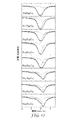
実施例1〜3アモルファスSi66−xSn4FexC30 Examples 1-3 amorphous Si 66-x Sn 4 Fe x C 30

適切な量の原材料(表1を参照されたい)を、直径0.5インチ(1.25cm)のクロム鋼ボール10kgと一緒に5Lの鉄製容器(内径7.4インチ(18.3cm))に入れた。容器にN2を吹き込み、98rpm(毎分回転)で10日間粉砕した。 Appropriate amount of raw material (see Table 1) is placed in a 5 L iron container (inside diameter 7.4 inches (18.3 cm)) with 10 kg of chrome steel balls 0.5 inches in diameter (1.25 cm). I put it in. N 2 was blown into the container and pulverized at 98 rpm (rotation per minute) for 10 days.
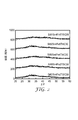
図1は、表1の組成物から製造した実施例1〜3の合金粉末のX線回折(XRD)パターンを示す。XRDプロットは、明確なピークを示さなかったことから、すべての合金がアモルファスであったことが示された。 FIG. 1 shows the X-ray diffraction (XRD) pattern of the alloy powders of Examples 1-3 produced from the compositions in Table 1. The XRD plot did not show a clear peak, indicating that all alloys were amorphous.
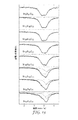
実施例4〜7アモルファスSi66−2ySn4FeyTiyC30
適切な量の原材料(表1を参照されたい)を、直径0.5インチ(1.25cm)のクロム鋼ボール10kgと一緒に5Lの鉄製容器(内径7.4インチ(18.3cm))に入れた。容器にN2を吹き込み、98rpm(毎分回転)で13日間粉砕した。
Examples 4-7 amorphous Si 66-2y Sn 4 Fe y Ti y C 30
Appropriate amount of raw material (see Table 1) is placed in a 5 L iron container (inside diameter 7.4 inches (18.3 cm)) with 10 kg of chrome steel balls 0.5 inches in diameter (1.25 cm). I put it in. N 2 was blown into the container and pulverized at 98 rpm (rotation per minute) for 13 days.
図2は、表2の組成物から製造した実施例4〜7の合金粉末のX線回折(XRD)パターンを示す。XRDプロットは、明確なピークを示さなかったことから、すべての合金がアモルファスであったことが示された。 FIG. 2 shows the X-ray diffraction (XRD) patterns of the alloy powders of Examples 4-7 produced from the compositions in Table 2. The XRD plot did not show a clear peak, indicating that all alloys were amorphous.
可逆性リチオ化/脱リチウム用活性成分としての合金の試験
バインダー処方
LiOH水溶液をポリ(アクリル酸)水溶液に加え、LiOH対アクリル酸が1:1モル比である溶液として、(アクリル酸)−Li塩(LiPAAとして設計)を製造した。LiPAAを製造するため、20重量% LiOH−H2O溶液及び34重量%ポリ(アクリル酸)を一緒に混合した。脱イオン水を加え、最終的な固形分10重量%のポリ(アクリル酸)−Li塩溶液を製造した。分子量250,000のポリ(アクリル酸)水溶液をAldrich Chemical(Milwaukee、WI)から得た。
Testing alloys as active ingredients for reversible lithiation / delithiation Binder formulation Add a LiOH aqueous solution to a poly (acrylic acid) aqueous solution, and a solution with a 1: 1 molar ratio of LiOH to acrylic acid (acrylic acid) -Li A salt (designed as LiPAA) was prepared. For producing LiPAA, it was mixed 20% by weight LiOH-H 2 O solution and 34 wt% poly (acrylic acid) together. Deionized water was added to produce a final 10% solids poly (acrylic acid) -Li salt solution. A poly (acrylic acid) aqueous solution with a molecular weight of 250,000 was obtained from Aldrich Chemical (Milwaukee, Wis.).
実施例1〜7用の電極処方
92重量%合金粉末:8重量% LiPAA
直径4.5インチ(1.25cm)のタングステン炭化物ボールを使用し、45mLステンレス鋼容器中で、1.84gの合金粉末(上記実施例1〜7)及び1.6gのLiPAA溶液(水中10%固形分)を混合した。速度2で1時間にわたって、遊星マイクロミル(PULVERISETTE 7モデル;Fritsch、Germany)で混合を実施した。3ミル(76マイクロメートル)ギャップを有するギャップダイを使用し、得られた溶液を手作業により厚さ10マイクロメートルのCu箔上に広げた。次に、真空オーブン中、120℃にて1〜2時間、サンプルを乾燥させた。
Electrode formulation for Examples 1-7 92 wt% alloy powder: 8 wt% LiPAA
1.84 g of alloy powder (Examples 1-7 above) and 1.6 g of LiPAA solution (10% in water) in a 45 mL stainless steel container using 4.5 inch (1.25 cm) diameter tungsten carbide balls. Solids). Mixing was performed on a planetary micromill (PULVERISETTE 7 model; Fritsch, Germany) for 1 hour at
試験用セル組み立て
2325−ボタンセルの電極として、直径16mmのディスクを打ち抜いた。各2325セルは、厚さ30ミル(0.76mm)、直径20mmのCuディスクスペーサー、直径18mmの合金電極ディスク、1つの直径20mmの多孔性マイクロセパレータ(Separation Products、Hoechst Celanese Corp.(Charlotte、NC)から入手可能なCELGARD 2400p))、直径18mm Li(厚さ0.38mmのリチウムリボン;Aldrich(Milwaukee、WI)から入手可能)並びに直径20mmの銅スペーサ(厚さ30ミル(0.76mm))から構成された。100マイクロリットルの電解質90重量%(1M LiPF6/[1EC:1EMC:1DMC(重量)]+10重量% FEC)を使用した。(EC/EMC/DMC中、1M LiPF6はFerro Chemicals(Ferro Corp.、Zachary、LA)のものであり、FEC(炭酸フルオロエチレン)は、Fujian Chuangxin Science And Technology(LTP、Fujian、China)のものであった)。ECは炭酸エチレンであり、EMCは炭酸エチルメチルであり、DMCは炭酸ジメチルであり、かつFECは2−フルオロカーボネートである。
Test Cell Assembly 2325—A 16 mm diameter disc was punched as the electrode of the button cell. Each 2325 cell has a 30 mil (0.76 mm) thick, 20 mm diameter Cu disk spacer, 18 mm diameter alloy electrode disk, one 20 mm diameter porous microseparator (Separation Products, Hoechst Celanese Corp. (Charlotte, NC). ) CELGARD 2400p)), 18 mm diameter Li (0.38 mm thick lithium ribbon; available from Aldrich (Milwaukee, Wis.)) And 20 mm diameter copper spacer (30 mil (0.76 mm) thick) Consists of. 100 microliters of
セルは、0.005V〜0.90V、100mA/合金gの一定速度、放電(脱リチウム)終了時、トリクル電流10mA/gで最初のサイクルを実施した。次からは、セルは、同範囲の電圧、200mA/合金gの速度、放電終了時、トリクル電流20mA/合金gでサイクルを実施した。セルは、ハーフサイクルごとの終わりで開回路にて15分間休止させた。これらの電極を有する試験セルの性能を表3に示す。総合して、合金は、多数サイクルにわたって可逆性のリチオ化/脱リチウムを示したため、充電式リチウムイオン電気化学セル用途において活性なアノード材料として使用するのに好適であった。 The cell was subjected to a first cycle with a trickle current of 10 mA / g at the end of discharge (delithiation) at a constant rate of 0.005 V to 0.90 V, 100 mA / g alloy, and discharge (delithiation). From the next, the cell was cycled at the same range of voltage, at a rate of 200 mA / g alloy, at the end of discharge, with a trickle current of 20 mA / g alloy. The cell was rested for 15 minutes in open circuit at the end of every half cycle. The performance of the test cell having these electrodes is shown in Table 3. Overall, the alloy exhibited reversible lithiation / delithiation over many cycles, making it suitable for use as an active anode material in rechargeable lithium ion electrochemical cell applications.
Sn−Si−Cコンビナトリアルライブラリ
J.R.Dahn,S.Trussler,T.D.Hatchard,A.Bonakdarpour,J.R.Mueller−Neuhaus,K.C.Hewitt and M.D.Fleischauer,Chem.Materials,14,3519(2002)に詳細に記載されているCorona真空式V3−T多元スパッタリング系コーターを使用し、Sn−Si−C系の擬二元コンビナトリアルライブラリを3つ作製した。ライブラリは、組成式Sn100−x−ySixCyにより識別した。式中、「y」は、約20、35、及び45であった。表4には、対象とする組成及び3つのライブラリの成膜パラメータを要約する。スパッタリング前に、ベース圧力1×10⁻⁷トル(1.3E−5Pa)に到達させた。直径2インチ(5cm)の3種の異なる標的を使用した:炭素標的(純度99.999%)はKurt J.Lesker Co.から得、スズ標的(純度99.85%)はAlfa Aesarから得たプレートから切り出し、ケイ素標的(純度99.99%)はWilliams Advanced Materialsから得た。成膜前に、すべての基材は最初にO2プラズマに、次にArプラズマに各15分間曝露した。望ましい成膜プロファイルを得るため、標的上に異なる固定マスクを設置した。成膜は、3sccmアルゴン流により実施した。成膜中、チャンバ圧はアルゴンガス1mTorr(0.13Pa)にて維持した。スパッタリングテーブルには各種基材:質量決定用銅ディスク、組成解析用銅箔、XRD測定用ケイ素(100)ウェハメスバウアー測定用カプトン箔、及び電気化学試験用コンビナトリアルセルプレート、を設置した。スパッタリングテーブルの角速度は40rpmとし、原子レベルで確実にSi、Sn、及びC原子を混合した。幅76mmのスパッタトラック上の連続性フィルムをこれらの基材に成膜した。3つのマスク(1つは各ライブラリ用)を設計して(1)ライブラリを通して一定量の炭素を得、(2)ケイ素対スズ量を直線的に変化させた。スパッタリングテーブルが標的上を通過するにつれ、厚さ原子1個分の層が成膜され、これにより確実に成膜時の原子規模での混合が行われた。
Sn-Si-C combinatorial library R. Dahn, S .; Trussler, T .; D. Hatchard, A .; Bonakdarpour, J. et al. R. Mueller-Neuhaus, K.M. C. Hewitt and M.M. D. Freischauer, Chem. Using a Corona vacuum V3-T multi-sputtering coater described in detail in Materials, 14, 3519 (2002), three Sn-Si-C-based pseudo binary combinatorial libraries were prepared. The library was identified by the composition formula Sn 100-xy Si x C y . In the formula, “y” was about 20, 35, and 45. Table 4 summarizes the composition of interest and the deposition parameters of the three libraries. Prior to sputtering, a base pressure of 1 × 10 −7 Torr (1.3E-5 Pa) was reached. Three different targets with a diameter of 2 inches (5 cm) were used: the carbon target (purity 99.999%) was purchased from Kurt J. Lesker Co. The tin target (purity 99.85%) was cut from a plate obtained from Alfa Aesar and the silicon target (purity 99.99%) was obtained from Williams Advanced Materials. Prior to deposition, all substrates were first exposed to O 2 plasma and then to Ar plasma for 15 minutes each. A different fixed mask was placed on the target to obtain the desired deposition profile. Film formation was performed with a 3 sccm argon flow. During film formation, the chamber pressure was maintained at 1 mTorr (0.13 Pa) of argon gas. Various substrates: a copper disk for mass determination, a copper foil for composition analysis, a silicon (100) wafer Mössbauer measurement Kapton foil, and an electrochemical test combinatorial cell plate were installed on the sputtering table. The angular velocity of the sputtering table was 40 rpm, and Si, Sn, and C atoms were reliably mixed at the atomic level. A continuous film on a sputter track having a width of 76 mm was formed on these substrates. Three masks (one for each library) were designed to (1) obtain a certain amount of carbon through the library, and (2) vary the silicon to tin amount linearly. As the sputtering table passed over the target, a layer of one atom thick was deposited, which ensured atomic scale mixing during deposition.
ザルトリウスSE−2微量天秤(精度0.1μg)を使用し、スパッタした材料の、単位面積あたりの質量の位置依存性を求めた。JEOL−8200 Superprobe電子マイクロプローブを使用し、波長分散型分光法(WDS)を用い、薄膜ライブラリ組成を計測し、意図した組成勾配が得られていることを確認した。組成物の測定結果を他の測定結果と一致させるため、マイクロプローブには移動ステージを取り付けた。銅製X線ターゲットチューブを取り付けたX線生成器と連結させたINEL CPS120湾曲位置有感検出器を使用し、X線測定値を収集した。バックグラウンドゼロの測定を行うため、基材として使用したケイ素(100)ウェハのブラッグの条件が満たされることを避け、サンプルに対するビームの入射角は約6°とした。回折ピーク(2θ=6°〜120°)を同時に、収集した。各組成物の捕捉時間は2400秒とした。隣接したX線回折スキャン間の距離として定義される、フィルムに対する空間分解能を、サンプルにおける組成勾配と組み合わせたところ、X線測定値用組成物では、Si及びSn原子は約±0.5%で不確実であった。 A Sartorius SE-2 microbalance (accuracy 0.1 μg) was used to determine the position dependency of the mass per unit area of the sputtered material. Using a JEOL-8200 Superprobe electron microprobe, the thin film library composition was measured using wavelength dispersion spectroscopy (WDS), and it was confirmed that the intended composition gradient was obtained. In order to make the measurement result of the composition coincide with other measurement results, a moving stage was attached to the microprobe. X-ray measurements were collected using an INEL CPS120 curved position sensitive detector coupled to an X-ray generator fitted with a copper X-ray target tube. In order to perform the measurement of zero background, the incident angle of the beam with respect to the sample was set to about 6 ° to avoid satisfying the Bragg condition of the silicon (100) wafer used as the substrate. Diffraction peaks (2θ = 6 ° -120 °) were collected simultaneously. The capture time for each composition was 2400 seconds. Combining the spatial resolution for the film, defined as the distance between adjacent X-ray diffraction scans, with the composition gradient in the sample, the composition for X-ray measurements is about ± 0.5% Si and Sn atoms. It was uncertain.
Ca119mSnO3供給源を取り付けた等加速度Wissel System IIスペクトロメーターを使用し、室温119Snメスバウアー効果スペクトルを収集した。系の速度スケールをCaSnO3に対して較正した。リードアパーチャを使用して、調査するフィルム部位を選択する。アパーチャ幅により、Si及びSn組成物のメスバウアー測定値については±2.0%の原子が不確実であった。 Using the constant acceleration Wissel System II spectrometer fitted with a Ca 119m SnO 3 source, were collected at room temperature 119 Sn Mossbauer spectra. The system speed scale was calibrated against CaSnO 3 . Using the lead aperture, select the film site to be investigated. Due to the aperture width, ± 2.0% atoms were uncertain for Mossbauer measurements of the Si and Sn compositions.
電気化学試験の際には、図3a〜dに例証する通りの樹脂系プリント回路基板をベースとした64チャネル電気化学セルプレートを使用した。このセルプレートの設計は、M.A.Al−Maghrabi,N.van der Bosch,R.J.Sanderson,D.A.Stevens,R.A.Dunlap,and J.R.Dahn,Electrochem.Solid−State Letters,14,1(2011)に見ることができる。コンビナトリアル電気化学セルは、M.D.Fleischauer,T.D.Hatchard,G.P.Rockwell,J.M.Topple,S.Trussler,S.K.Jericho,M.H.Jericho and J.R.Dahn,J.Electrochem.Soc.,150,A1465(2003).に記載の通りに構成した。V.K.Cumyn,M.D.Fleischauer,T.D.Hatchard and J.R.Dahn,Electrochem.Solid−State Letters 6,E15,(2003)に記載の通りに多チャネル擬ポテンショスタットを用い、セルプレートの64チャネルに対し、低速度走査サイクリック・ボルタンメトリー測定を実施した。セルは、Li/Li+に対し1.2〜0.005Vで合計27サイクルにわたって放電/充電した。各放電又は充電の際のスキャン時間は、最初の3サイクルは12時間とし、第4サイクル〜24サイクルは3時間とし、第25、26及び27サイクルでは再び12時間とした。このような操作を行い、最初の3サイクル及び最後の3サイクルで得られたスロー・サイクリック・ボルタンメトリー測定値を比較することにより、27サイクル中に生じ得る電極変化を注意深く監視した。
In the electrochemical test, a 64-channel electrochemical cell plate based on a resin-based printed circuit board as illustrated in FIGS. This cell plate design is described in M.M. A. Al-Maglabi, N .; van der Bosch, R.A. J. et al. Sanderson, D.M. A. Stevens, R.M. A. Dunlap, and J.M. R. Dahn, Electrochem. Solid-State Letters, 14, 1 (2011). Combinatorial electrochemical cells are described in M.C. D. Freischauer, T .; D. Hatchard, G .; P. Rockwell, J. et al. M.M. Topple, S.M. Trussler, S.M. K. Jericho, M .; H. Jericho and J.H. R. Dahn, J .; Electrochem. Soc. 150, A1465 (2003). As described in 1. V. K. Cumyn, M .; D. Freischauer, T .; D. Hatchard and J.H. R. Dahn, Electrochem. Low-speed scanning cyclic voltammetry measurements were performed on 64 channels of the cell plate using a multi-channel pseudopotentiostat as described in Solid-
図4は、作製した3つのライブラリの組成物を示すSn−Si−C系のギブスの三角相図を示す(表4を参照されたい)。この図は、Sn及びSi含量を変化させ、かつ約一定量の炭素を獲得させたライブラリを示すものである。図中、影をつけた領域は、X線回折により測定された通りにアモルファスな範囲を示す。X線パターンで鮮明な回折ピークが検出されず、アモルファス様の「こぶ」のブロードのみが検出された場合に、材料はアモルファスであると判定した。 FIG. 4 shows a triangular phase diagram of a Sn—Si—C based Gibbs showing the composition of the three libraries produced (see Table 4). This figure shows a library in which Sn and Si contents are changed and an approximately constant amount of carbon is obtained. In the figure, the shaded area indicates an amorphous area as measured by X-ray diffraction. When no clear diffraction peak was detected in the X-ray pattern and only an amorphous-like “bump” broad was detected, the material was determined to be amorphous.
マイクロプローブ解析から得られた組成を、図5に示す通り「ライブラリクロージャ」により確認した(例えば、P.Liao,B.L.MacDonald,R.A.Dunlap and J.R.Dahn,Chem.Mater.,20,454(2008)を参照されたい)。この図中、典型的なライブラリの単位面積当たりの組成及び質量を、ライブラリと一致させて位置の関数としてプロットする。図5aは、単位面積当たりのC(◇)、Sn(▲)、及びSi(■)のモル数を示す。それぞれ、スパッタリングマスクの「一定」、「線形入力」及び「線形出力」により定義される。図5bは、図5aから算出された組成を、波長分散分光法により測定された組成と一致させて示す。 The composition obtained from the microprobe analysis was confirmed by a “library closure” as shown in FIG. 5 (for example, P. Liao, B.L. , 20, 454 (2008)). In this figure, the composition and mass per unit area of a typical library is plotted as a function of position, consistent with the library. FIG. 5a shows the number of moles of C (◇), Sn (▲), and Si (■) per unit area. Defined by the “constant”, “linear input” and “linear output” of the sputtering mask, respectively. FIG. 5b shows the composition calculated from FIG. 5a consistent with the composition measured by wavelength dispersion spectroscopy.
図5cは、Sn100−x−ySixCyライブラリ(10<x<65及びy=約20)に関し、各計量ディスクに対しスパッタしたフィルムについて測定された質量(○)を、図5a中の曲線から算出された質量(実線)と比較する。他の2つのライブラリは同様の結果を示した。 FIG. 5c is for the Sn100-xySixCy library (10 <x <65 and y = about 20), and the mass (O) measured for the sputtered film for each metering disk is calculated from the curve in FIG. 5a. Compare with the mass (solid line). The other two libraries showed similar results.
図6a及び6bcは、本解析で表される3つのライブラリ(表4に要約)のX線回折(XRD)試験結果を示す。各サンプル組成物を示す。図6aは、ライブラリ1のSn100−x−ySixCyの組成範囲をカバーする回折パターンを選択し、示す。本解析で試験した組成物に関し、アモルファス又はナノ構造化相では、スズ含量は8≦(100−x−y)≦43の範囲であることが判明した。図7は、ライブラリ2の回折パターンを示す。このパターンでは、アモルファス又はナノ構造化範囲は7≦(100−x−y)≦37の範囲であることが判明した。図8に示されるとおり、この範囲は、ライブラリ3では5≦(100−x−y)≦42に延長されていた。これらのすべての範囲において、薄膜は2θ=29かつ44°に中心を置く幅広いピークを有し、これまでにT.D.Hatchard and J.R.Dahn,J.Electrochem.Soc.,151,A1628(2004)に報告されているアモルファス又はナノ構造化ケイ素の反射と厳密に一致した。
6a and 6bc show the X-ray diffraction (XRD) test results of the three libraries represented in this analysis (summarized in Table 4). Each sample composition is shown. FIG. 6 a shows the selected diffraction pattern covering the composition range of Sn 100-xy Si x C y in library 1. For the compositions tested in this analysis, the tin content was found to be in the range of 8 ≦ (100−xy) ≦ 43 in the amorphous or nanostructured phase. FIG. 7 shows a diffraction pattern of the
これまでの報告に見られる通り(例えば、上掲Hatchard及びDahnを参照されたい)、この領域(アモルファス)は、確実に低Sn含量に延び、かつ(100−x−y)=0軸を包含する。ライブラリ1〜3に関し、スズ量はそれぞれ特定の割合(100−x−y)≧51(100−x−y)≧46及び(100−x−y)≧48を超え、回折ピークは、2θ=30.6°、32.0°、44.0°、及び45.0°のピークで出現し、これは結晶質スズ(正方晶系、I41/amd)を反映する(200)、(101)、(220)、及び(211)に相当する。ライブラリ3は、最も大きい範囲で、アモルファス又はナノ構造化されていることが判明した組成を有した。アモルファス範囲の富Sn制限により、C含量は体系的に変化し、及びライブラリ1〜3におけるSn:Si原子比は、各々約1:1、1.2:1及び3:1に一致した。Beaulieu et al.,J.Electrochem.Soc.,150,A149(2003)は、スパッタリング法により製造したSi100−xSnx電極の構造を報告している。彼らは、x≦36を有するサンプルにおいてSi100−xSnxのアモルファス相が観察され、この相がSn:Si比0.8:1に相当するものと報告している。Si100−xSnxスパッタリングフィルムのアモルファス範囲は、0<x<50である場合(1:1比に相当)に得られたと報告されている。これらの測定により、図4に例示される通り、アモルファス範囲は、本解析で試験された領域(炭素含有)の下流から、y=0(炭素不含有)にまで延びるものと示される。これまでに報告されているSn:Si比と、本解析で得られた報告との比較により、炭素含量がアモルファス範囲を延長させる役割を果たすことが示される。SiCが形成される可能性はあるものの、出願者らのサンプルでは結晶質炭化ケイ素ピークは観察されなかった。概して、本解析の結果により、本解析で製造した組成物の大部分がアモルファス又はナノ構造化物であることが示され、構造的観点により、電極材としての使用が見込まれることが示される。 As seen in previous reports (see, for example, Hatchard and Dahn above), this region (amorphous) reliably extends to low Sn content and includes the (100−xy) = 0 axis. To do. Regarding libraries 1 to 3, the tin amount exceeds a specific ratio (100−xy) ≧ 51 (100−xy) ≧ 46 and (100−xy) ≧ 48, and the diffraction peak is 2θ = Appears at peaks of 30.6 °, 32.0 °, 44.0 °, and 45.0 °, which reflects crystalline tin (tetragonal, I41 / amd) (200), (101) , (220), and (211). Library 3 had the largest composition found to be amorphous or nanostructured. Due to the Sn-rich limit in the amorphous range, the C content was systematically varied and the Sn: Si atomic ratios in Libraries 1-3 were consistent with about 1: 1, 1.2: 1 and 3: 1, respectively. Beaulieu et al. , J .; Electrochem. Soc. , 150, A149 (2003) report the structure of a Si 100-x Sn x electrode manufactured by a sputtering method. They report that an amorphous phase of Si 100-x Sn x is observed in the sample with x ≦ 36, which corresponds to a Sn: Si ratio of 0.8: 1. It is reported that the amorphous range of Si 100-x Sn x sputtering film was obtained when 0 <x <50 (corresponding to 1: 1 ratio). These measurements show, as illustrated in FIG. 4, that the amorphous range extends from downstream of the region tested in this analysis (carbon containing) to y = 0 (carbon free). Comparison of the Sn: Si ratio reported so far with the reports obtained in this analysis shows that the carbon content plays a role in extending the amorphous range. Although SiC may form, no crystalline silicon carbide peak was observed in Applicants' samples. In general, the results of this analysis indicate that the majority of the compositions produced in this analysis are amorphous or nanostructured, and that structural use is expected to be used as electrode material.
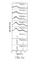
図7b、図7bcにおけるFig.7b、及び図8bcにおけるFig.8bは、3つのSn100−x−ySixCyコンビナトリアルライブラリの、選択した微分容量対電位プロットを示す。各サンプル組成物を示す。最初の3回のサイクルを示す。ライブラリ1、2、及び3の結果を細密に検査した所、放電及び充電の両方の間それぞれ8≦(100−x−y)≦43、7≦(100−x−y)≦37、及び5≦(100−x−y)≦42のこぶ様のブロードを有するなめらかな曲線が示された。このようなプロファイルは、アモルファスシリコンスパッタ薄膜の特性と類似するものであり、本サンプル中に存在するスズ結晶はわずかであることが示される。これらの組成物のXRDパターンは、材料がアモルファス又はナノ構造化物であることを示す。各ライブラリの結晶部位には、微分容量対電位曲線に明瞭なピークが観察された。概して、微分容量対電位曲線における明瞭なピークは、Sn結晶の存在についての指標となり、XRDパターンを示す図中の対応するパネルにより、スズ結晶が存在することが確認された。ケイ素及び炭素マトリックス内に分散したスズが凝集を開始し、スズ結晶領域を形成する遷移点が存在するものと考えられる。
FIG. 7b and FIG. 7b and FIG. 8b shows selected differential capacity versus potential plots of three Sn 100-xy Si x C y combinatorial libraries. Each sample composition is shown. The first three cycles are shown. A close examination of the results of
図6bcにおけるFig.6c、図7bcにおけるFig.7c、及び6cは、パネル(a)及び(b)に示すものと同一のサンプルの具体的な容量対サイクル数を示す。図6bcにおけるFig.6cは、組成物についての急速分解セル容量を示す。これらの組成物は、1)XRDパターン、及び微分容量対電位曲線(パネルの底部に向かう)により明らかであるように、スズ結晶を含有していることが判明し、かつ2)酸素濃度が高いことが判明している(パネルの上部に向かう)富Si領域では、サンプルの電子マイクロプローブ測定により、富Si領域が、ライブラリ中の他の領域と比較してより高い酸素含量を有することが判明した。他では、容量は、約27サイクル後も初期値の90%以内を維持した。これらの電解質はなんらカーボンブラック又はバインダーを含有しないことから、このような分解は、任意のサイクル中の体積の膨張に伴う機械的なクラックにより生じ得る。図9a〜9cは、それぞれライブラリ1〜3の容量対サイクル数を示す。これらのプロットを細密に観察することにより、次のような所見をなすことができる:1)サンプルの大部分は、最初のサイクルにおいて、文献で報告されている、本質的には合金製負極に共通の課題である高不可逆的容量に悩まされることがなく、及び2)望ましくない容量損失は、上記の通り、富Si及び富Sn領域の両方において組成と関連付けられる。 FIG. Fig. 6c, Fig. 7bc. 7c and 6c show the specific capacity versus cycle number of the same sample as shown in panels (a) and (b). FIG. 6c shows the rapid degradation cell capacity for the composition. These compositions were found to contain 1) tin crystals, as evidenced by 1) the XRD pattern, and differential capacity versus potential curve (towards the bottom of the panel), and 2) high oxygen concentration In the rich Si region, which is known (towards the top of the panel), electron microprobe measurements of the sample reveal that the rich Si region has a higher oxygen content compared to other regions in the library did. In others, the capacity remained within 90% of the initial value after about 27 cycles. Since these electrolytes do not contain any carbon black or binder, such decomposition can be caused by mechanical cracks associated with volume expansion during any cycle. Figures 9a-9c show the capacity versus number of cycles for libraries 1-3, respectively. By closely observing these plots, the following observations can be made: 1) The majority of the samples are in the first cycle reported in the literature, essentially in the alloy negative electrode. The common problem, high irreversible capacity, is not bothered, and 2) undesired capacity loss is associated with composition in both Si-rich and Sn-rich regions, as described above.
図10は、ライブラリ1(Sn34Si47C19)、ライブラリ2(Sn37Si31C32)、及びライブラリ3(Sn35Si22C43)の最良のパフォーマンスを示すセルの電荷対容量のプロットを示す。この図は、同じセルの、最初の3サイクル及び最後の3サイクルの微分容量対電位も示す。図10aは、プラトーを示さず、滑らかで安定している充電及び放電曲線を明瞭に示す。図に示される通り、このセルに対して達成される容量は1450mAh/gである。組成物の電気化学性能は図10aに類似しているものの、炭素は含有しない。この組成物の容量は約2000mAh/gであったものの、ほんの10サイクル後には大部分の容量が減衰していることが観察された。図10bは、ライブラリ2のサンプルの優れた容量保持性を示す。放電及び充電中のこの組成物の安定性は、27サイクル後に容量1060mAh/gを有し、充電及び放電中の曲線がなめらかであることにより反映される。図10cに観察することができる通り、同様の考察をライブラリ3に適用することができる。
FIG. 10 is a plot of cell charge versus capacity showing the best performance of Library 1 (Sn 34 Si 47 C 19 ), Library 2 (Sn 37 Si 31 C 32 ), and Library 3 (Sn 35 Si 22 C 43 ). Indicates. The figure also shows the differential capacity versus potential for the first three cycles and the last three cycles of the same cell. FIG. 10a clearly shows a smooth and stable charge and discharge curve without a plateau. As shown in the figure, the capacity achieved for this cell is 1450 mAh / g. The electrochemical performance of the composition is similar to FIG. 10a, but does not contain carbon. Although the capacity of this composition was about 2000 mAh / g, it was observed that most of the capacity had decayed after only 10 cycles. FIG. 10b shows the excellent capacity retention of the
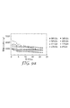
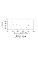
活性物質中に存在する相を知ることで、特定の容量の測定値を理解することが可能になる。大部分の文献は、得られた容量を、見込まれる相に予想される容量と比較していない。図11a〜11cは、それぞれ、上記の通り、3つのライブラリから選択された電極の初回の充電(脱リチウム)の際の理論容量を表す。 Knowing the phases present in the active substance makes it possible to understand the measured value of a specific volume. Most literature does not compare the capacity obtained to that expected for the expected phase. FIGS. 11a to 11c each represent the theoretical capacity during the initial charge (delithiation) of the electrodes selected from the three libraries as described above.
図11は、測定された容量(●)及び理論容量(▲)から、Li15Si4、Li22Sn4及びLiC6では、室温相にてそれぞれSi、Sn、及びCが完全にリチオ化されているものと推測され、並びに理論容量(実線)から、Li15Si4及びLi22Sn4では、室温相にてそれぞれSi及びSnが完全にリチオ化されており、かつ炭素の容量はほんのわずかであるものと推測されることが示される。図11aは、理論値及び観測値が、特に高Sn含量に関しては妥当に一致していることを示す。Sn含量を減少させるにつれ、特に炭素含量がより高いライブラリ2及び3においては、観察された容量は、理論容量と比較して大幅に低下した。この容量の減少は、不活性なSiCナノ結晶の形成によるものである可能性が高い。
FIG. 11 shows that Li 15 Si 4 , Li 22 Sn 4 and LiC 6 are completely lithiated in the room temperature phase from the measured capacity (●) and theoretical capacity (▲), respectively. From the theoretical capacity (solid line), in Li 15 Si 4 and Li 22 Sn 4 , Si and Sn are completely lithiated in the room temperature phase, respectively, and the capacity of carbon is very small. It is shown that it is estimated that. FIG. 11a shows that the theoretical and observed values are reasonably consistent, especially for high Sn content. As the Sn content was decreased, the observed capacity decreased significantly compared to the theoretical capacity, especially in
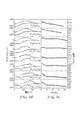
図12は、約20%の炭素を有し、記載の組成を有するライブラリ1のサンプルの、室温での119Snメスバウアー効果スペクトルを示す。これらは2つのローレンツ成分と一致した;本質的に純粋なSn相の一重項は中央に+2.54mm/sだけシフトし、かつSi−Sn相から得られる、四極子分裂を示す二重項は、さほど中央へとシフトしない。ライブラリにわたってスズを増量させるにつれ、スズ相に対応する一重項ピークは、Sn−Si相にて強度が向上した。これは、恐らく、カーボンマトリックスにおいてスズ領域の凝集が増加したことに起因する。スズ濃度が微量な場合でさえ、スズ領域が存在していることは明らかであった。 FIG. 12 shows the 119 Sn Mossbauer effect spectrum at room temperature for a sample of Library 1 having about 20% carbon and having the described composition. These were consistent with the two Lorentz components; the singlet of the essentially pure Sn phase was shifted by +2.54 mm / s to the center, and the doublet showing quadrupole splitting obtained from the Si-Sn phase is , Don't shift so much to the center. As the amount of tin increased across the library, the singlet peak corresponding to the tin phase increased in strength in the Sn-Si phase. This is probably due to increased aggregation of tin regions in the carbon matrix. It was clear that the tin region was present even when the tin concentration was very small.
図13は、およそ30%の炭素を有し、記載の組成を有するライブラリ2のサンプルの、119Snメスバウアー効果スペクトルを示す。46%以下のSnを有するサンプルから回収されたスペクトルは、良好に二重項と一致した。スズの濃度を増加させた場合には、スペクトルに一重項が現れることから、スズが凝集することが証明された。ライブラリの富スズ領域に存在するわずかな特徴は、0mm/s付近に中央がシフトするローレンツの一重項成分として表される、少量のスズ酸化物と一致する。Snの凝集は、最大でSnの46%まで阻害されたことは、図13から明らかである。これにより、炭素の添加は、サンプルのミクロ構造を定義する重要な役割を果たすことが示される。
FIG. 13 shows the 119 Sn Mossbauer effect spectrum of a sample of
図14は、およそ45%の炭素を有し、記載の組成を有するライブラリ3のサンプルの、119Snメスバウアー効果スペクトルを示す。これらのスペクトルを細密に観察することにより、Sn−Si相の二重項成分に加え、純粋なスズに由来するごく僅かな一重項成分を見ることができる。これまでの2つのライブラリに示される傾向によると、炭素含量を増加させることにより、スズの凝集は更に阻害される。上記電気化学試験に基づき示される通り、SiCが形成されることで、得られることになるSn:Si相のSiが結合に用いられ、Snが排出されることになり、最終的には、炭素が遊離スズの形成を完全に排除する能力が制限される恐れがある。 FIG. 14 shows the 119 Sn Mossbauer effect spectrum of a sample of Library 3 having approximately 45% carbon and the described composition. By closely observing these spectra, in addition to the doublet component of the Sn—Si phase, it is possible to see very few singlet components derived from pure tin. According to the trends shown in the two previous libraries, increasing the carbon content further inhibits tin aggregation. As shown based on the above electrochemical test, by forming SiC, Sn of Si: Si phase to be obtained is used for bonding, Sn is discharged, and finally, carbon May limit the ability to completely eliminate the formation of free tin.
図15〜17は、それぞれライブラリ1〜3のSn−Si成分の四極子分裂、中央シフト、及び相対面積を示す。図15は、ライブラリにおいて、Sn含量に応じ四極子分裂が減少し、及び中央シフトが増加することを示す。これらの結果は、アモルファスSn−Siが短距離配向へと変化した証拠となる。これは、次の通りに説明することができる:「Sn−Siの隣接するペアをSn−Snの隣接するペアにより置き換えた場合に、よりポジティブな中央シフトが観察されたならば、Si中Snの中央シフト(+1.88mm/s)は、Sn中Sn(+2.54mm/s)の中央シフトよりもポジティブさに劣ることになる」。Sn−Si結合を、Sn−Sn結合により置き換えることで、より対称的なSn環境が生じ、かつこれは四極子分裂の減少に一致する。対称なSn環境は、四極子分裂が0であることに相当する。この観察は、図16及び図17に例示される通り、他の2つのライブラリについて観察されたものと一致する。 FIGS. 15-17 show the quadrupole splitting, center shift, and relative area of the Sn—Si components of Libraries 1-3, respectively. FIG. 15 shows that in the library, quadrupole division decreases and median shift increases with Sn content. These results provide evidence that amorphous Sn-Si has changed to short-range orientation. This can be explained as follows: “If a more positive central shift is observed when an adjacent pair of Sn—Si is replaced by an adjacent pair of Sn—Sn, then Sn in Si The center shift of (+1.88 mm / s) will be less positive than the center shift of Sn (+2.54 mm / s) in Sn. Replacing Sn-Si bonds with Sn-Sn bonds results in a more symmetric Sn environment, which is consistent with a decrease in quadrupole splitting. A symmetric Sn environment corresponds to zero quadrupole splitting. This observation is consistent with that observed for the other two libraries, as illustrated in FIGS.
本発明の範囲及び趣旨から逸脱することなく、本発明の様々な改変及び変更が当業者には明らかとなるであろう。本発明は、本明細書で述べる例示的な実施形態及び実施例によって不当に限定されるものではないこと、また、こうした実施例及び実施形態は、本明細書において以下に記述する特許請求の範囲によってのみ限定されると意図する本発明の範囲に関する例示のためにのみ提示されることを理解すべきである。本開示に引用される参照文献はすべて、その全体が本明細書に組み込まれる。 Various modifications and alterations of this invention will become apparent to those skilled in the art without departing from the scope and spirit of this invention. The present invention is not unduly limited by the exemplary embodiments and examples described herein, and such examples and embodiments are claimed in the claims herein below. It should be understood that this is presented only for illustration regarding the scope of the invention, which is intended to be limited only by. All references cited in this disclosure are incorporated herein in their entirety.
Claims (19)
前記合金がアモルファスである、リチウムイオン電気化学セル用負極組成物。 Including alloys having the formula Si x Sn q M y C z , where q, x, y, and z are mole fractions, q, x, and z are greater than 0, and M is one or more. A transition metal of
A negative electrode composition for a lithium ion electrochemical cell, wherein the alloy is amorphous.
ミルに、ケイ素、スズ、遷移金属ケイ酸塩、及びグラファイトを含む混合物を充填する工程であって、ケイ素、スズ、1つ以上の遷移金属及びグラファイトのモル分率が、式SixSnqMyCzにおいて、q、x、y及びzにより表され、q、x及びzは0超であり、Mは1つ以上の遷移金属であり、0.50≦x≦0.83、0.02≦y≦0.10、0.25≦z≦0.35、及び0.02≦q≦0.05である、工程と、
前記混合物をボールミリングする工程と、
前記混合物を真空オーブンで乾燥させる工程と、を含む、方法。 A method for producing an alloy for a negative electrode composition for a lithium ion electrochemical cell, comprising:
Filling a mill with a mixture comprising silicon, tin, transition metal silicate, and graphite, wherein the mole fraction of silicon, tin, one or more transition metals and graphite is of the formula Si x Sn q M y C z is represented by q, x, y and z, q, x and z are greater than 0, M is one or more transition metals, 0.50 ≦ x ≦ 0.83, 0. A process of 02 ≦ y ≦ 0.10, 0.25 ≦ z ≦ 0.35, and 0.02 ≦ q ≦ 0.05;
Ball milling the mixture;
Drying the mixture in a vacuum oven.
Applications Claiming Priority (3)
| Application Number | Priority Date | Filing Date | Title |
|---|---|---|---|
| US201161545368P | 2011-10-10 | 2011-10-10 | |
| US61/545,368 | 2011-10-10 | ||
| PCT/US2012/059284 WO2013055646A1 (en) | 2011-10-10 | 2012-10-09 | Amorphous alloy negative electrode compositions for lithium-ion electrochemical cells |
Publications (2)
| Publication Number | Publication Date |
|---|---|
| JP2014531737A true JP2014531737A (en) | 2014-11-27 |
| JP2014531737A5 JP2014531737A5 (en) | 2015-11-26 |
Family
ID=48082333
Family Applications (1)
| Application Number | Title | Priority Date | Filing Date |
|---|---|---|---|
| JP2014535777A Pending JP2014531737A (en) | 2011-10-10 | 2012-10-09 | Amorphous alloy negative electrode composition for lithium ion electrochemical cell |
Country Status (6)
| Country | Link |
|---|---|
| US (1) | US20140261899A1 (en) |
| EP (1) | EP2766944A4 (en) |
| JP (1) | JP2014531737A (en) |
| KR (1) | KR20140083009A (en) |
| CN (1) | CN103843177A (en) |
| WO (1) | WO2013055646A1 (en) |
Families Citing this family (12)
| Publication number | Priority date | Publication date | Assignee | Title |
|---|---|---|---|---|
| JP5751448B2 (en) | 2011-05-25 | 2015-07-22 | 日産自動車株式会社 | Negative electrode active material for lithium ion secondary battery |
| JP5904364B2 (en) * | 2011-12-27 | 2016-04-13 | 日産自動車株式会社 | Negative electrode active material for electrical devices |
| JP6040997B2 (en) * | 2012-11-22 | 2016-12-07 | 日産自動車株式会社 | Negative electrode for lithium ion secondary battery and lithium ion secondary battery using the same |
| WO2014080886A1 (en) | 2012-11-22 | 2014-05-30 | 日産自動車株式会社 | Negative electrode for electrical device, and electrical device using same |
| KR20180031067A (en) | 2012-11-22 | 2018-03-27 | 닛산 지도우샤 가부시키가이샤 | Negative electrode for electrical device, and electrical device using the same |
| WO2015111187A1 (en) | 2014-01-24 | 2015-07-30 | 日産自動車株式会社 | Electrical device |
| JP6202106B2 (en) | 2014-01-24 | 2017-09-27 | 日産自動車株式会社 | Electrical device |
| CA2944454A1 (en) | 2014-04-01 | 2015-10-08 | The Research Foundation For The State University Of New York | Electrode materials for group ii cation-based batteries |
| JP6696200B2 (en) * | 2016-02-12 | 2020-05-20 | 株式会社豊田自動織機 | Negative electrode binder, intermediate composition, negative electrode, power storage device, negative electrode slurry, polymer compound manufacturing method, and negative electrode manufacturing method |
| US11177471B2 (en) | 2016-12-16 | 2021-11-16 | Johnson Matthey Public Company Limited | Anode materials for lithium ion batteries and methods of making and using same |
| FR3073863A1 (en) * | 2017-11-22 | 2019-05-24 | Centre National De La Recherche Scientifique | PASSIVE COMPOSITE MATERIAL FOR ELECTRODE |
| CN111200126A (en) * | 2020-01-17 | 2020-05-26 | 三峡大学 | Preparation method of amorphous tin/carbon material as lithium ion battery negative electrode material |
Citations (5)
| Publication number | Priority date | Publication date | Assignee | Title |
|---|---|---|---|---|
| JP2007149604A (en) * | 2005-11-30 | 2007-06-14 | Sanyo Electric Co Ltd | Negative electrode for lithium secondary battery and lithium secondary battery |
| JP2008016446A (en) * | 2006-06-09 | 2008-01-24 | Canon Inc | Powder material, electrode structure using powder material, power storage device having the electrode structure, and manufacturing method of powder material |
| JP2008204885A (en) * | 2007-02-22 | 2008-09-04 | Matsushita Electric Ind Co Ltd | Nonaqueous electrolyte battery |
| US20100119942A1 (en) * | 2008-11-11 | 2010-05-13 | Sujeet Kumar | Composite compositions, negative electrodes with composite compositions and corresponding batteries |
| US20100288077A1 (en) * | 2009-05-14 | 2010-11-18 | 3M Innovative Properties Company | Method of making an alloy |
Family Cites Families (9)
| Publication number | Priority date | Publication date | Assignee | Title |
|---|---|---|---|---|
| JP3620703B2 (en) * | 1998-09-18 | 2005-02-16 | キヤノン株式会社 | Negative electrode material for secondary battery, electrode structure, secondary battery, and production method thereof |
| JP2001052691A (en) * | 1999-08-09 | 2001-02-23 | Toshiba Corp | Nonaqueous electrolyte secondary battery |
| US7851085B2 (en) * | 2005-07-25 | 2010-12-14 | 3M Innovative Properties Company | Alloy compositions for lithium ion batteries |
| US7906238B2 (en) * | 2005-12-23 | 2011-03-15 | 3M Innovative Properties Company | Silicon-containing alloys useful as electrodes for lithium-ion batteries |
| US7875388B2 (en) * | 2007-02-06 | 2011-01-25 | 3M Innovative Properties Company | Electrodes including polyacrylate binders and methods of making and using the same |
| US20090053589A1 (en) * | 2007-08-22 | 2009-02-26 | 3M Innovative Properties Company | Electrolytes, electrode compositions, and electrochemical cells made therefrom |
| WO2009131700A2 (en) * | 2008-04-25 | 2009-10-29 | Envia Systems, Inc. | High energy lithium ion batteries with particular negative electrode compositions |
| WO2010047828A1 (en) * | 2008-10-24 | 2010-04-29 | Primet Precision Materials, Inc. | Group iva small particle compositions and related methods |
| EP2239803A1 (en) * | 2009-04-10 | 2010-10-13 | Saft Groupe Sa | Active material composition for the negative electrode of a lithium-ion accumulator. |
-
2012
- 2012-10-09 US US14/350,367 patent/US20140261899A1/en not_active Abandoned
- 2012-10-09 EP EP12840549.5A patent/EP2766944A4/en not_active Withdrawn
- 2012-10-09 CN CN201280048874.3A patent/CN103843177A/en active Pending
- 2012-10-09 KR KR1020147012206A patent/KR20140083009A/en not_active Application Discontinuation
- 2012-10-09 JP JP2014535777A patent/JP2014531737A/en active Pending
- 2012-10-09 WO PCT/US2012/059284 patent/WO2013055646A1/en active Application Filing
Patent Citations (5)
| Publication number | Priority date | Publication date | Assignee | Title |
|---|---|---|---|---|
| JP2007149604A (en) * | 2005-11-30 | 2007-06-14 | Sanyo Electric Co Ltd | Negative electrode for lithium secondary battery and lithium secondary battery |
| JP2008016446A (en) * | 2006-06-09 | 2008-01-24 | Canon Inc | Powder material, electrode structure using powder material, power storage device having the electrode structure, and manufacturing method of powder material |
| JP2008204885A (en) * | 2007-02-22 | 2008-09-04 | Matsushita Electric Ind Co Ltd | Nonaqueous electrolyte battery |
| US20100119942A1 (en) * | 2008-11-11 | 2010-05-13 | Sujeet Kumar | Composite compositions, negative electrodes with composite compositions and corresponding batteries |
| US20100288077A1 (en) * | 2009-05-14 | 2010-11-18 | 3M Innovative Properties Company | Method of making an alloy |
Also Published As
| Publication number | Publication date |
|---|---|
| KR20140083009A (en) | 2014-07-03 |
| WO2013055646A1 (en) | 2013-04-18 |
| EP2766944A4 (en) | 2015-06-10 |
| EP2766944A1 (en) | 2014-08-20 |
| US20140261899A1 (en) | 2014-09-18 |
| CN103843177A (en) | 2014-06-04 |
Similar Documents
| Publication | Publication Date | Title |
|---|---|---|
| JP2014531737A (en) | Amorphous alloy negative electrode composition for lithium ion electrochemical cell | |
| KR101323974B1 (en) | Silicon-containing alloys useful as electrodes for lithium-ion batteries | |
| KR101281359B1 (en) | Alloy Compositions for Lithium Ion Batteries | |
| EP3005450B1 (en) | Electrode composition, electrochemical cell and method of making electrochemical cells | |
| US20090111022A1 (en) | Electrode compositions and methods | |
| Wu et al. | Study of electrochemical performance and thermal property of LiNi0. 5Co0. 2Mn0. 3O2 cathode materials coated with a novel oligomer additive for high-safety lithium-ion batteries | |
| KR20090109570A (en) | Electrodes including novel binders and methods of making and using the same | |
| KR20090115798A (en) | Electrolytes, electrode compositions and electrochemical cells made therefrom | |
| KR20080074157A (en) | Negative active substance, and negative electrode and lithium ion secondary battery using the substance | |
| KR101548394B1 (en) | Sintered cathode compositions | |
| US11901551B2 (en) | Silicon based materials for and method of making and using same | |
| KR20150088826A (en) | Anode Compositions For Sodium-ion Batteries And Methods Of Making Same | |
| JP7350817B2 (en) | Anode material for lithium ion batteries and its manufacturing and usage methods | |
| Yu et al. | Carbon nanotubes coating on LiNi0. 8Co0. 15Al0. 05O2 as cathode materials for lithium battery | |
| KR20090113890A (en) | Electrolytes, electrode compositions, and electrochemical cells made therefrom | |
| JP2004220906A (en) | Lithium secondary battery negative electrode member and its manufacturing method | |
| Du et al. | Surface modification of a LiNi 0.5 Mn 1.5 O 4 cathode with lithium boron oxide glass for lithium-ion batteries | |
| KR20200142020A (en) | Anode material, and method of making and using the same | |
| US20240079593A1 (en) | Self-crosslinking composite binders for electrodes |
Legal Events
| Date | Code | Title | Description |
|---|---|---|---|
| A521 | Request for written amendment filed |
Free format text: JAPANESE INTERMEDIATE CODE: A523 Effective date: 20151006 |
|
| A621 | Written request for application examination |
Free format text: JAPANESE INTERMEDIATE CODE: A621 Effective date: 20151006 |
|
| A977 | Report on retrieval |
Free format text: JAPANESE INTERMEDIATE CODE: A971007 Effective date: 20160824 |
|
| A131 | Notification of reasons for refusal |
Free format text: JAPANESE INTERMEDIATE CODE: A131 Effective date: 20160906 |
|
| A02 | Decision of refusal |
Free format text: JAPANESE INTERMEDIATE CODE: A02 Effective date: 20170328 |