WO2012160650A1 - 内燃機関の触媒被毒検出装置 - Google Patents
内燃機関の触媒被毒検出装置 Download PDFInfo
- Publication number
- WO2012160650A1 WO2012160650A1 PCT/JP2011/061879 JP2011061879W WO2012160650A1 WO 2012160650 A1 WO2012160650 A1 WO 2012160650A1 JP 2011061879 W JP2011061879 W JP 2011061879W WO 2012160650 A1 WO2012160650 A1 WO 2012160650A1
- Authority
- WO
- WIPO (PCT)
- Prior art keywords
- fuel ratio
- air
- catalyst
- poisoning
- rich
- Prior art date
- Legal status (The legal status is an assumption and is not a legal conclusion. Google has not performed a legal analysis and makes no representation as to the accuracy of the status listed.)
- Ceased
Links
Images



Classifications
-
- F—MECHANICAL ENGINEERING; LIGHTING; HEATING; WEAPONS; BLASTING
- F02—COMBUSTION ENGINES; HOT-GAS OR COMBUSTION-PRODUCT ENGINE PLANTS
- F02D—CONTROLLING COMBUSTION ENGINES
- F02D41/00—Electrical control of supply of combustible mixture or its constituents
- F02D41/02—Circuit arrangements for generating control signals
- F02D41/021—Introducing corrections for particular conditions exterior to the engine
- F02D41/0235—Introducing corrections for particular conditions exterior to the engine in relation with the state of the exhaust gas treating apparatus
-
- F—MECHANICAL ENGINEERING; LIGHTING; HEATING; WEAPONS; BLASTING
- F01—MACHINES OR ENGINES IN GENERAL; ENGINE PLANTS IN GENERAL; STEAM ENGINES
- F01N—GAS-FLOW SILENCERS OR EXHAUST APPARATUS FOR MACHINES OR ENGINES IN GENERAL; GAS-FLOW SILENCERS OR EXHAUST APPARATUS FOR INTERNAL-COMBUSTION ENGINES
- F01N11/00—Monitoring or diagnostic devices for exhaust-gas treatment apparatus
- F01N11/007—Monitoring or diagnostic devices for exhaust-gas treatment apparatus the diagnostic devices measuring oxygen or air concentration downstream of the exhaust apparatus
-
- F—MECHANICAL ENGINEERING; LIGHTING; HEATING; WEAPONS; BLASTING
- F01—MACHINES OR ENGINES IN GENERAL; ENGINE PLANTS IN GENERAL; STEAM ENGINES
- F01N—GAS-FLOW SILENCERS OR EXHAUST APPARATUS FOR MACHINES OR ENGINES IN GENERAL; GAS-FLOW SILENCERS OR EXHAUST APPARATUS FOR INTERNAL-COMBUSTION ENGINES
- F01N13/00—Exhaust or silencing apparatus characterised by constructional features
- F01N13/009—Exhaust or silencing apparatus characterised by constructional features having two or more separate purifying devices arranged in series
- F01N13/0093—Exhaust or silencing apparatus characterised by constructional features having two or more separate purifying devices arranged in series the purifying devices are of the same type
-
- F—MECHANICAL ENGINEERING; LIGHTING; HEATING; WEAPONS; BLASTING
- F02—COMBUSTION ENGINES; HOT-GAS OR COMBUSTION-PRODUCT ENGINE PLANTS
- F02D—CONTROLLING COMBUSTION ENGINES
- F02D41/00—Electrical control of supply of combustible mixture or its constituents
- F02D41/02—Circuit arrangements for generating control signals
- F02D41/14—Introducing closed-loop corrections
- F02D41/1438—Introducing closed-loop corrections using means for determining characteristics of the combustion gases; Sensors therefor
- F02D41/1439—Introducing closed-loop corrections using means for determining characteristics of the combustion gases; Sensors therefor characterised by the position of the sensor
- F02D41/1441—Plural sensors
-
- F—MECHANICAL ENGINEERING; LIGHTING; HEATING; WEAPONS; BLASTING
- F02—COMBUSTION ENGINES; HOT-GAS OR COMBUSTION-PRODUCT ENGINE PLANTS
- F02D—CONTROLLING COMBUSTION ENGINES
- F02D41/00—Electrical control of supply of combustible mixture or its constituents
- F02D41/02—Circuit arrangements for generating control signals
- F02D41/14—Introducing closed-loop corrections
- F02D41/1438—Introducing closed-loop corrections using means for determining characteristics of the combustion gases; Sensors therefor
- F02D41/1444—Introducing closed-loop corrections using means for determining characteristics of the combustion gases; Sensors therefor characterised by the characteristics of the combustion gases
- F02D41/1454—Introducing closed-loop corrections using means for determining characteristics of the combustion gases; Sensors therefor characterised by the characteristics of the combustion gases the characteristics being an oxygen content or concentration or the air-fuel ratio
-
- F—MECHANICAL ENGINEERING; LIGHTING; HEATING; WEAPONS; BLASTING
- F01—MACHINES OR ENGINES IN GENERAL; ENGINE PLANTS IN GENERAL; STEAM ENGINES
- F01N—GAS-FLOW SILENCERS OR EXHAUST APPARATUS FOR MACHINES OR ENGINES IN GENERAL; GAS-FLOW SILENCERS OR EXHAUST APPARATUS FOR INTERNAL-COMBUSTION ENGINES
- F01N2550/00—Monitoring or diagnosing the deterioration of exhaust systems
- F01N2550/02—Catalytic activity of catalytic converters
-
- F—MECHANICAL ENGINEERING; LIGHTING; HEATING; WEAPONS; BLASTING
- F01—MACHINES OR ENGINES IN GENERAL; ENGINE PLANTS IN GENERAL; STEAM ENGINES
- F01N—GAS-FLOW SILENCERS OR EXHAUST APPARATUS FOR MACHINES OR ENGINES IN GENERAL; GAS-FLOW SILENCERS OR EXHAUST APPARATUS FOR INTERNAL-COMBUSTION ENGINES
- F01N2560/00—Exhaust systems with means for detecting or measuring exhaust gas components or characteristics
- F01N2560/02—Exhaust systems with means for detecting or measuring exhaust gas components or characteristics the means being an exhaust gas sensor
- F01N2560/025—Exhaust systems with means for detecting or measuring exhaust gas components or characteristics the means being an exhaust gas sensor for measuring or detecting O2, e.g. lambda sensors
-
- F—MECHANICAL ENGINEERING; LIGHTING; HEATING; WEAPONS; BLASTING
- F01—MACHINES OR ENGINES IN GENERAL; ENGINE PLANTS IN GENERAL; STEAM ENGINES
- F01N—GAS-FLOW SILENCERS OR EXHAUST APPARATUS FOR MACHINES OR ENGINES IN GENERAL; GAS-FLOW SILENCERS OR EXHAUST APPARATUS FOR INTERNAL-COMBUSTION ENGINES
- F01N2560/00—Exhaust systems with means for detecting or measuring exhaust gas components or characteristics
- F01N2560/14—Exhaust systems with means for detecting or measuring exhaust gas components or characteristics having more than one sensor of one kind
-
- F—MECHANICAL ENGINEERING; LIGHTING; HEATING; WEAPONS; BLASTING
- F01—MACHINES OR ENGINES IN GENERAL; ENGINE PLANTS IN GENERAL; STEAM ENGINES
- F01N—GAS-FLOW SILENCERS OR EXHAUST APPARATUS FOR MACHINES OR ENGINES IN GENERAL; GAS-FLOW SILENCERS OR EXHAUST APPARATUS FOR INTERNAL-COMBUSTION ENGINES
- F01N3/00—Exhaust or silencing apparatus having means for purifying, rendering innocuous, or otherwise treating exhaust
- F01N3/08—Exhaust or silencing apparatus having means for purifying, rendering innocuous, or otherwise treating exhaust for rendering innocuous
- F01N3/10—Exhaust or silencing apparatus having means for purifying, rendering innocuous, or otherwise treating exhaust for rendering innocuous by thermal or catalytic conversion of noxious components of exhaust
- F01N3/101—Three-way catalysts
-
- Y—GENERAL TAGGING OF NEW TECHNOLOGICAL DEVELOPMENTS; GENERAL TAGGING OF CROSS-SECTIONAL TECHNOLOGIES SPANNING OVER SEVERAL SECTIONS OF THE IPC; TECHNICAL SUBJECTS COVERED BY FORMER USPC CROSS-REFERENCE ART COLLECTIONS [XRACs] AND DIGESTS
- Y02—TECHNOLOGIES OR APPLICATIONS FOR MITIGATION OR ADAPTATION AGAINST CLIMATE CHANGE
- Y02T—CLIMATE CHANGE MITIGATION TECHNOLOGIES RELATED TO TRANSPORTATION
- Y02T10/00—Road transport of goods or passengers
- Y02T10/10—Internal combustion engine [ICE] based vehicles
- Y02T10/12—Improving ICE efficiencies
-
- Y—GENERAL TAGGING OF NEW TECHNOLOGICAL DEVELOPMENTS; GENERAL TAGGING OF CROSS-SECTIONAL TECHNOLOGIES SPANNING OVER SEVERAL SECTIONS OF THE IPC; TECHNICAL SUBJECTS COVERED BY FORMER USPC CROSS-REFERENCE ART COLLECTIONS [XRACs] AND DIGESTS
- Y02—TECHNOLOGIES OR APPLICATIONS FOR MITIGATION OR ADAPTATION AGAINST CLIMATE CHANGE
- Y02T—CLIMATE CHANGE MITIGATION TECHNOLOGIES RELATED TO TRANSPORTATION
- Y02T10/00—Road transport of goods or passengers
- Y02T10/10—Internal combustion engine [ICE] based vehicles
- Y02T10/40—Engine management systems
Definitions
- the present invention relates to a catalyst poisoning detection apparatus for an internal combustion engine.
- an internal combustion engine having a configuration in which exhaust gas sensors are arranged upstream and downstream of a catalyst to calculate the oxygen storage capacity (OSC) of the catalyst.
- a catalyst poisoning detection apparatus is known.
- an upstream catalyst and a downstream catalyst are disposed in the exhaust passage, and the first O 2 sensor is disposed between them, and the second O 2 is disposed downstream of the latter.
- Two sensors are arranged respectively.
- the oxygen storage capacity (OSC) of the upstream catalyst is detected by forcibly oscillating the air-fuel ratio, and the deterioration of the upstream catalyst is detected based on whether the OSC is greater than a predetermined value.
- the air-fuel ratio control that performs such forced oscillation is also referred to as active control.
- the catalyst deterioration detection device discloses a configuration in which exhaust gas sensors are provided upstream and downstream of the catalyst, there is an actual disclosure as a configuration in which the exhaust gas sensor is disposed downstream of the catalyst.
- the air-fuel ratio sensor can generate a substantially linear output according to the oxygen concentration in the exhaust gas, whereas the O 2 sensor is a sensor that greatly changes the output before and after the oxygen concentration in the exhaust gas exceeds a predetermined value. It is.
- Various configurations are known for arranging this type of O 2 sensor downstream of the catalyst, including the active control technology disclosed in the above publication and the technology of performing sub-feedback control in air-fuel ratio control.
- the inventor of the present application has conducted extensive research and found a novel technique of estimating the poisoning of the catalyst by providing an air-fuel ratio sensor downstream of the catalyst and evaluating the output characteristics of the air-fuel ratio sensor downstream of the catalyst. It was. That is, the catalyst has an ability to occlude an appropriate amount of oxygen (oxygen occlusion ability), and if the exhaust gas contains unburned components such as HC and CO, the occluded oxygen To oxidize those components. In such a reaction process, the oxygen storage and release of the catalyst proceed at a specific rate (the oxygen storage rate and the oxygen release rate, respectively). On the other hand, it is known that the oxygen release rate decreases due to poisoning of the catalyst.
- the function of the O 2 sensor that is, the function of greatly changing the output before and after the oxygen concentration in the exhaust gas exceeds a predetermined value is the known forced air-fuel ratio control (known active control) used in the above-mentioned conventional technology. ) And the function for measuring the oxygen storage capacity according to the above, and the function required for the conventional catalyst deterioration detecting device.
- the above-mentioned O 2 sensor is necessary for the novel catalyst deterioration detection technology found by the inventors of the present application, “the catalyst downstream air-fuel ratio caused by the change in the oxygen release rate of the catalyst due to poisoning. It is impossible to detect “change in stoichiometric convergence characteristics”.
- the catalyst deterioration detection due to poisoning is performed using the “change in stoichiometric convergence characteristics of the catalyst downstream air-fuel ratio due to the change in oxygen release rate of the catalyst due to poisoning”.
- the present invention has been made to solve the above-described problems. Based on the output of an air-fuel ratio sensor provided downstream of the catalyst, the present invention makes good use of changes in the oxygen release rate of the catalyst due to poisoning.
- An object of the present invention is to provide a catalyst poisoning detection device for an internal combustion engine that can detect catalyst poisoning with high accuracy.
- a first invention is a catalyst poisoning detection device for detecting poisoning of a catalyst in an internal combustion engine in which a catalyst having an oxygen storage capacity is provided in an exhaust passage, comprising a catalyst downstream air-fuel ratio sensor, an air-fuel ratio controller, And an estimation unit for estimating the poisoning of the catalyst.
- the catalyst downstream air-fuel ratio sensor is an air-fuel ratio sensor provided in a position downstream of the catalyst disposed in the exhaust passage in the exhaust passage of the internal combustion engine.
- the air-fuel ratio control unit is configured to change the rich air-fuel ratio from the lean air-fuel ratio so as to switch the air-fuel ratio of the exhaust gas upstream of the catalyst between the rich air-fuel ratio that is rich with respect to the stoichiometric air-fuel ratio and the lean air-fuel ratio that is lean.
- Lean rich control for changing the air-fuel ratio of the exhaust gas to the air-fuel ratio and rich-lean control for changing the air-fuel ratio of the exhaust gas from the rich air-fuel ratio to the lean air-fuel ratio are performed.
- the estimation unit includes an output value of the output of the catalyst downstream air-fuel ratio sensor corresponding to the lean-rich control until it converges from a lean air-fuel ratio to a theoretical air-fuel ratio, and / or the catalyst corresponding to the rich-lean control. Based on the output value of the downstream air-fuel ratio sensor output from the rich air-fuel ratio until it converges to the stoichiometric air-fuel ratio, the poisoning of the catalyst is estimated.
- the estimation unit includes at least one of the following two period estimation units.
- the first period estimating unit correlates the length of the period until the convergence from the lean air-fuel ratio to the stoichiometric air-fuel ratio in the output of the catalyst downstream air-fuel ratio sensor according to the lean rich control or the length of the period. Based on the parameters possessed, the presence or absence of poisoning of the catalyst or the amount of poisoning of the catalyst is estimated.
- the second period estimating unit correlates the length of the period until the convergence from the rich air-fuel ratio to the stoichiometric air-fuel ratio in the output of the catalyst downstream air-fuel ratio sensor according to the rich lean control or the length of the period. Based on the parameters possessed, the presence or absence of poisoning of the catalyst or the amount of poisoning of the catalyst is estimated.
- the estimation unit includes at least one of the following two estimation calculation units.
- the first estimation calculation unit includes the catalyst downstream air-fuel ratio sensor based on an output value during convergence from the lean air-fuel ratio to the stoichiometric air-fuel ratio in the output of the catalyst downstream air-fuel ratio sensor according to the lean rich control.
- a predetermined function that defines the relationship between the output value of the catalyst and the poisoning of the catalyst, the presence or absence of poisoning of the catalyst or the amount of poisoning of the catalyst is estimated.
- the second estimation calculation unit is configured to output the catalyst downstream air-fuel ratio sensor based on an output value during convergence from the rich air-fuel ratio to the stoichiometric air-fuel ratio in the output of the catalyst downstream air-fuel ratio sensor according to the rich lean control.
- a predetermined function that defines the relationship between the output value of the catalyst and the poisoning of the catalyst, the presence or absence of poisoning of the catalyst or the amount of poisoning of the catalyst is estimated.
- the estimation unit includes an overshoot calculation unit, a lean rich behavior characteristic value calculation unit, a rich lean behavior characteristic value calculation unit, and an area difference calculation unit. At least two calculation units are included.
- the overshoot calculation unit has a large overshoot to the rich air-fuel ratio side in the output value during the convergence from the lean air-fuel ratio to the stoichiometric air-fuel ratio in the output of the catalyst downstream air-fuel ratio sensor according to the lean-rich control. Is calculated.
- the lean rich behavior characteristic value calculation unit calculates the theoretical air fuel ratio based on the output value during the convergence from the lean air fuel ratio to the stoichiometric air fuel ratio at the output of the catalyst downstream air fuel ratio sensor in accordance with the lean rich control. The length of the period until convergence or the slope of the change in the air-fuel ratio due to the output of the catalyst downstream air-fuel ratio sensor is calculated.
- the rich-lean behavior characteristic value calculation unit calculates the theoretical air-fuel ratio based on an output value during convergence from the rich air-fuel ratio to the stoichiometric air-fuel ratio in the output of the catalyst downstream air-fuel ratio sensor according to the rich-lean control.
- the area difference calculation unit is configured to output an output waveform in the rich air-fuel ratio region based on an output value of the catalyst downstream air-fuel ratio sensor according to a reciprocation between the rich air-fuel ratio and the lean air-fuel ratio controlled by the air-fuel ratio control unit.
- the difference between the area formed by the theoretical air-fuel ratio and the area formed by the output waveform in the lean air-fuel ratio area and the theoretical air-fuel ratio is calculated.
- the predetermined function according to the third aspect of the invention is the overshoot size calculated by the overshoot calculation unit, the length of the period calculated by the lean rich behavior characteristic value calculation unit. Two or more selected from the group consisting of the length or the slope, the length of the period or the slope calculated by the rich lean behavior characteristic value calculator, and the difference calculated by the area difference calculator , And a poisoning accumulation amount of the catalyst, including a function that determines a predetermined different weighting factor for each of the two or more values.
- the estimation unit includes at least one of the following first to sixth poisoning estimation units.
- the first poisoning estimation unit causes an output value of the output of the catalyst downstream air-fuel ratio sensor corresponding to the lean-rich control to exceed the rich air-fuel ratio side during the convergence from the lean air-fuel ratio to the stoichiometric air-fuel ratio.
- the estimation of poisoning of the catalyst is performed based on the presence or absence of a chute or based on the magnitude of overshoot to the rich air-fuel ratio side in the output value.
- the second poisoning estimation unit is configured to output the output value of the catalyst downstream air-fuel ratio with respect to the time axis of the output value of the output of the catalyst downstream air-fuel ratio sensor corresponding to the lean rich control while converging from the lean air-fuel ratio to the stoichiometric air-fuel ratio.
- the poisoning of the catalyst is estimated based on the inclination of the air-fuel ratio change based on the output of the sensor.
- the third poisoning estimation unit is configured to reduce the downstream of the catalyst with respect to the time axis in the process of convergence from the rich air-fuel ratio to the stoichiometric air-fuel ratio in the air-fuel ratio based on the output of the catalyst downstream air-fuel ratio sensor according to the rich lean control.
- the poisoning of the catalyst is estimated based on the inclination of the air-fuel ratio change based on the output of the air-fuel ratio sensor.
- the fourth poisoning estimation unit is a rich air-fuel ratio at an air-fuel ratio based on an output of the catalyst downstream air-fuel ratio sensor according to a reciprocation between a rich air-fuel ratio and a lean air-fuel ratio controlled by the air-fuel ratio control unit.
- the poisoning of the catalyst is estimated based on the area of the region formed by the waveform in the region and the theoretical air-fuel ratio.
- the fifth poisoning estimation unit is a lean air-fuel ratio at an air-fuel ratio based on the output of the catalyst downstream air-fuel ratio sensor in response to a reciprocation between the rich air-fuel ratio and the lean air-fuel ratio controlled by the air-fuel ratio control unit.
- the poisoning of the catalyst is estimated based on the area of the region formed by the waveform in the region and the theoretical air-fuel ratio.
- the sixth poisoning estimation unit is a rich air-fuel ratio at an air-fuel ratio based on the output of the catalyst downstream air-fuel ratio sensor according to the reciprocation between the rich air-fuel ratio and the lean air-fuel ratio controlled by the air-fuel ratio control unit.
- the air-fuel ratio control unit includes an open-loop air-fuel ratio control unit that performs air-fuel ratio control by open-loop control.
- the unit estimates the poisoning of the catalyst based on the rich peak value during the rich air-fuel ratio control in the open loop control.
- the estimation unit includes at least one of the following two poisoning estimation units.
- the first poisoning estimation unit compares the output value while converging from the lean air-fuel ratio to the stoichiometric air-fuel ratio in the output of the catalyst downstream air-fuel ratio sensor according to the lean rich control, and a predetermined value. Based on the above, the presence or absence of poisoning of the catalyst or the amount of poisoning of the catalyst is estimated.
- the second poisoning estimation unit compares the output value while converging from the rich air-fuel ratio to the stoichiometric air-fuel ratio in the output of the catalyst downstream air-fuel ratio sensor according to the rich lean control, and a predetermined value. Based on the above, the presence or absence of poisoning of the catalyst or the amount of poisoning of the catalyst is estimated.
- An eighth invention is a catalyst poisoning detection device for detecting catalyst poisoning in an internal combustion engine in which a catalyst having an oxygen storage capacity is provided in an exhaust passage, the catalyst downstream air-fuel ratio detection means, active control means, And estimating means for estimating the poisoning of the catalyst.
- the catalyst downstream air-fuel ratio detection means detects the value of the air-fuel ratio of the exhaust gas at a position downstream of the catalyst disposed in the exhaust passage of the internal combustion engine.
- the active control means performs active control for switching the air-fuel ratio of the exhaust gas upstream of the catalyst between a rich air-fuel ratio that is rich with respect to the stoichiometric air-fuel ratio and a lean air-fuel ratio that is lean.
- the estimation means includes a value of the air-fuel ratio of the exhaust gas until it converges from the lean air-fuel ratio corresponding to the active control to the stoichiometric air-fuel ratio, and / or the rich air-fuel ratio corresponding to the active control to the stoichiometric air-fuel ratio. Based on the value of the air-fuel ratio of the exhaust gas until it converges to, the relationship of the change in the oxygen release rate of the catalyst according to the poisoning amount of the catalyst and the exhaust gas according to the oxygen release rate of the catalyst The catalyst poisoning is estimated using the relationship of the change in the gas air-fuel ratio waveform.
- the ninth invention is a catalyst deterioration detection device for an internal combustion engine, A catalyst poisoning detection device for an internal combustion engine according to any one of the first to eighth inventions; Means for detecting the deterioration of the catalyst of the internal combustion engine, including the result of the estimation of poisoning of the catalyst by the catalyst poisoning detection device; It is characterized by providing.
- the oxygen release rate of the catalyst decreases according to the amount of poisoning.
- the influence of the change in the oxygen release rate appears in the behavior of the air-fuel ratio from the lean or rich downstream of the catalyst to the convergence to the stoichiometric air-fuel ratio. Therefore, according to the first aspect of the invention, the poisoning of the catalyst can be detected with good accuracy by utilizing the fact that the influence of such a change in the oxygen release rate of the catalyst can be detected by the air-fuel ratio sensor.
- the catalyst coverage is based on the length of the period from the lean air-fuel ratio to the stoichiometric air-fuel ratio at the output of the air-fuel ratio sensor downstream of the catalyst. Poison can be detected.
- the third invention it is possible to estimate the presence or absence of catalyst poisoning or the amount of catalyst poisoning by performing a calculation according to a predetermined function using the output value of the air-fuel ratio sensor. it can.
- the fourth aspect of the invention it is possible to calculate two or more parameters from the output value of the air-fuel ratio sensor and perform calculation with weighting on these parameters. Thereby, poisoning of the catalyst can be detected with good accuracy.
- various parameters that can be identified from the waveform of the air-fuel ratio behavior downstream of the catalyst can be used for estimation of catalyst poisoning.
- the sixth aspect of the invention it is possible to estimate the poisoning of the catalyst by using a point where there is a correlation between the rich peak value during the rich A / F control and the oxygen release rate.
- the seventh aspect by comparing the output value of the air-fuel ratio sensor with a predetermined value, it is possible to estimate the presence or absence of catalyst poisoning or the amount of catalyst poisoning.
- the poisoning of the catalyst can be detected with good accuracy by utilizing the point that the influence of the change in the oxygen release rate of the catalyst appears in the air-fuel ratio downstream of the catalyst.
- the ninth aspect of the present invention it is possible to determine the deterioration of the catalyst of the internal combustion engine by including the result of highly accurate catalyst poisoning estimation based on the output value of the air-fuel ratio sensor downstream of the catalyst.
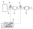
- FIG. 1 is a diagram showing a configuration of a catalyst poisoning detection apparatus for an internal combustion engine according to an embodiment of the present invention, together with a part of the configuration of the internal combustion engine to which the apparatus is applied.
- the internal combustion engine to which the control device of the present embodiment is applied is an internal combustion engine for automobiles, and more specifically, a premixed combustion type 4-stroke 1-cycle reciprocating engine.
- the catalyst deterioration detection device of the present embodiment is realized as one function of an ECU (Electronic Control Unit) that comprehensively controls the operation of such an internal combustion engine.
- ECU Electronic Control Unit
- crank angle a rotation angle CA of the crankshaft.
- a cylinder head is assembled to the upper part of the cylinder block, and the space from the upper surface of the piston to the cylinder head forms a combustion chamber.
- the cylinder head is provided with a spark plug that ignites the air-fuel mixture in the combustion chamber.
- the cylinder head of the engine 10 includes an intake port communicating with the combustion chamber, and an intake valve is provided at a connection portion between the intake port and the combustion chamber.
- An intake passage is connected to the intake port, and an injector that injects fuel in the vicinity of the intake port is provided in the intake passage.
- a direct injection injector that injects fuel directly into the combustion chamber may be provided.
- a throttle valve is provided upstream of the injector.
- the throttle valve is an electronically controlled valve that is driven by a throttle motor.
- the throttle valve is driven based on the accelerator opening AA detected by the accelerator opening sensor.
- a throttle opening sensor for detecting the throttle opening is provided in the vicinity of the throttle valve.
- a hot-wire air flow meter is provided upstream of the throttle valve.
- the air flow meter is configured to detect an intake air amount Ga.
- An air cleaner is provided upstream of the air flow meter.
- the cylinder head of the engine 10 includes an exhaust port communicating with the combustion chamber.
- An exhaust valve is provided at the connection between the exhaust port and the combustion chamber.
- An exhaust passage 20 is connected to the exhaust port.
- the exhaust passage 20 is provided with a three-way catalyst (S / C) 30 (hereinafter simply referred to as “catalyst 30”) for purifying the exhaust gas.
- a limit current type air-fuel ratio sensor 40 is provided upstream of the catalyst 30 in the exhaust passage 20.
- a limit current type air-fuel ratio sensor 42 is also provided at a position downstream of the catalyst 30 in the exhaust passage 20.
- a three-way catalyst 32 (hereinafter simply referred to as “catalyst 32”) is further provided downstream of the air-fuel ratio sensor 42 in the exhaust passage.
- Both the air-fuel ratio sensors 40 and 42 are connected to the ECU 60.
- OBD regulations are strengthened, and catalytic precious metals are reduced, an air-fuel ratio control system with high controllability and robustness is required.
- a system in which air-fuel ratio sensors for example, limit current type air-fuel ratio sensors
- S / C three-way catalyst
- the present embodiment applies the output processing technique of the air-fuel ratio sensor according to the present invention in such an air-fuel ratio control system in which air-fuel ratio sensors are arranged before and after the catalyst.
- the engine 10 includes an ECU (Electronic Control Unit) 60 as a control device.
- An ignition plug, an injector, a throttle motor, and the like are connected to the output side of the ECU 60.
- a coolant temperature sensor, a crank angle sensor, an accelerator opening sensor, a throttle opening sensor, an air flow meter, an air-fuel ratio sensor, and the like are connected to the input side of the ECU 60.
- the ECU 60 calculates the engine speed NE based on the output of the crank angle sensor. Further, the ECU 60 calculates the engine load KL based on the accelerator opening AA detected by the accelerator opening sensor.
- the ECU 60 determines the fuel injection amount based on the engine speed NE, the engine load KL, and the like.
- the ECU 60 drives the actuators and executes the operation control while detecting the operation information of the engine by the sensor system.
- the ECU60 is provided with the active control part 62, the Cmax calculation part 64, and the catalyst poisoning estimation part 66 as shown in FIG. 1 besides the engine control part as mentioned above.
- the active control unit 62 controls the target air-fuel ratio of the air-fuel mixture supplied into the cylinder to forcibly set the exhaust air-fuel ratio upstream of the catalyst to the fuel lean side (hereinafter abbreviated as “lean side”) and the fuel.
- Control also referred to as “active control” that switches between the rich side (hereinafter abbreviated as “rich side”) can be executed.
- the Cmax calculation unit 64 can calculate the value of the maximum oxygen storage amount Cmax based on the output value of the air-fuel ratio sensor 40 according to the active control by the active control unit 62.
- the catalyst poisoning estimation unit 66 is a control unit for executing a process for realizing “a catalyst poisoning degree estimation technique” according to an embodiment described later.
- FIG. 2 is a cross-sectional view showing the sensor element unit 50 of the air-fuel ratio sensors 40 and 42 in the catalyst poisoning detection apparatus for an internal combustion engine according to the embodiment of the present invention.
- the sensor element unit 50 has a solid electrolyte layer as the detection element 51.
- the solid electrolyte layer 51 is made of partially stabilized zirconia and has oxygen ion conductivity.
- a measurement electrode 52 is provided on one surface of the solid electrolyte layer 51.
- an atmosphere side electrode also referred to as “reference gas side electrode” 53 is provided on the other surface of the solid electrolyte layer 51.
- Both the measurement electrode 52 and the atmosphere side electrode 53 are made of platinum or the like, and are connected to the ECU 60 via leads 58a and 58b, respectively.
- a porous diffusion resistance layer 54 is formed on one surface of the solid electrolyte layer 51.
- the porous diffusion resistance layer 54 has a gas permeable layer 54a for covering the measurement electrode 52 and introducing exhaust gas to the measurement electrode 52, and a gas blocking layer 54b for suppressing the permeation of exhaust gas. Yes.
- the gas permeable layer 54a and the gas barrier layer 54b are made of ceramics such as alumina and zirconia, and have different average pore diameters and porosity.
- An air introduction duct 55 is formed on the other surface of the solid electrolyte layer 51.
- the air introduction duct 55 has an air chamber (also referred to as “reference gas chamber”) 56 at the top.
- the atmosphere side electrode 53 is disposed in the atmosphere chamber 56.
- the air introduction duct 55 is made of high thermal conductive ceramic such as alumina.
- a heater 57 is provided on the lower surface of the air introduction duct 55.
- the heater 57 includes a plurality of heating elements 57a that generate heat when energized, and an insulating layer 57b that covers the heating elements 57a.
- the heating element 57a is connected to the ECU 60 via a lead 58c.
- the sensor element unit 50 having such a configuration can detect the oxygen concentration by a linear characteristic and can output a critical current corresponding to the oxygen concentration to the ECU 60.
- This air-fuel ratio sensor output (critical current) has a correlation with the air-fuel ratio of the exhaust gas. Specifically, the critical current increases as the air-fuel ratio of the exhaust gas becomes leaner, and the critical current decreases as the air-fuel ratio of the exhaust gas becomes richer.
- sensor output signals extracted from the air-fuel ratio sensors 40 and 42 are used for control processing in the ECU 60 after being subjected to predetermined signal processing.
- This signal processing includes frequency signal processing using band pass filters such as so-called LPF and HPF, and the function of such signal processing is mounted on the ECU 60 or realized by another arithmetic processing unit.
- the exhaust gas air-fuel ratio upstream of the catalyst is forcibly changed from the rich side (or lean side) to the lean side (or rich side), and then the oxygen sensor output downstream of the catalyst changes (inverts).
- the maximum oxygen storage amount Cmax of the catalyst 30 can be calculated by calculating the oxygen excess / deficiency amount of the exhaust gas flowing into the catalyst 30 during the time until. That is, the maximum oxygen storage amount Cmax of the catalyst 30 can be calculated by executing active control.
- a / F with catalyst in the upper part of FIG. 3 corresponds to the target A / F of the exhaust gas upstream of the catalyst 30.
- Air-fuel ratio control (control of the target A / F of the engine 10 and fuel injection amount control) is performed in the ECU 60 so that this “catalyst A / F” is realized, and the exhaust gas flows into the catalyst 30, and the exhaust gas
- the air-fuel ratio sensor 40 outputs an output signal corresponding to the oxygen concentration.
- the lean A / F value is 14.1 and the rich A / F value is 15.1.
- the width of the target A / F in the active control is set from 14.1 to 15.1.
- the “catalyst output A / F” in the lower part of FIG. 3 indicates the output waveform of the air-fuel ratio sensor 42 downstream of the catalyst 30.
- the solid line indicates the signal waveform of “the state where S poisoning (that is, sulfur poisoning) occurs”, and the signal waveform of the broken line indicates the signal waveform of “the state where there is no S poisoning”. Is shown.
- the output of the air-fuel ratio sensor 42 indicates lean.
- the target A / F is switched from lean A / F to rich A / F as shown in “A / F with catalyst” in FIG. In FIG. 3, the time t 1 is equivalent to that time.
- rich exhaust gas is discharged from the cylinder, and the output of the air-fuel ratio sensor 40 is rich.
- the output of the air-fuel ratio sensor 42 changes so as to converge from lean to stoichiometric as in region A in FIG.
- the flow of this series of processes is as follows.
- the catalyst 30 stores oxygen to the full oxygen storage capacity OSC, and then the target A / F is switched to the rich side, so that the oxygen in the catalyst 30 marks the time t 2 by is exhausted. That is, integrated value of the rich side output shown is an air-fuel ratio sensor 40 during a period from time t 1 to time t 2 is equivalent to the amount of oxygen released from the catalyst 30 during the period from the time t 1 to time t 2 is doing.
- the insufficient oxygen amount in the exhaust gas is set to rich from time t 1 to time t 2, the can estimate the release of oxygen amount of the catalyst 30.
- the target A / F is set to the lean side target value, consisting of the cylinder to lean exhaust gas is discharged.
- the output of the air-fuel ratio sensor 40 upstream of the catalyst 30 shows lean.
- lean exhaust gas flows into the catalyst 30, excess oxygen in the exhaust gas is occluded in the catalyst 30.
- oxygen is occluded in the catalyst 30, lean exhaust gas does not blow through the catalyst 30.
- the oxygen of the oxygen storage capacity OSC is stored in the catalyst 30 and the oxygen storage capacity of the catalyst 30 is saturated, lean exhaust gas blows out from the catalyst 30. For this reason, the output of the air-fuel ratio sensor 42 changes to the lean side.
- time t 3 is equivalent to that time.
- the oxygen storage capacity OSC full oxygen occluded in the catalyst 30 is it marks the time t 3 in. That is, the value the air-fuel ratio sensor 40 is obtained by integrating the lean side output shown during a period from time t 2 to time t 3, corresponding to the occluded amount of oxygen in the catalyst 30 during the period from time t 2 to time t 3 is doing.
- the excess oxygen content in the exhaust gas is set to lean from time t 2 to time t 3, it is possible to determine the oxygen storage amount of the catalyst 30.
- the maximum oxygen storage amount Cmax of the catalyst 30 can be obtained by repeating such control a predetermined number of times and calculating and averaging a predetermined number of released oxygen amounts and stored oxygen amounts. When the maximum oxygen storage amount Cmax is smaller than the reference value, it can be determined that the catalyst 30 has deteriorated.
- FIGS. 3 to 9 are diagrams for explaining a technique for estimating the degree of catalyst poisoning used in the catalyst poisoning detecting apparatus for an internal combustion engine according to the embodiment of the present invention.
- the technique for estimating the degree of poisoning according to the present embodiment can estimate the degree of influence when “catalyst poisoning that reduces the oxygen release rate of the catalyst” occurs. Specifically, by providing an air-fuel ratio sensor downstream of the catalyst and evaluating the output characteristics of the air-fuel ratio sensor downstream of the catalyst, S poisoning as “catalyst poisoning that reduces the oxygen release rate of the catalyst” ( That is, the degree of poisoning is estimated for sulfur poisoning). That is, the catalyst 30 has an ability to occlude an appropriate amount of oxygen (oxygen occlusion ability), and occludes when unburned components such as HC and CO are contained in the exhaust gas.
- oxygen occlusion ability oxygen occlusion ability
- Oxygen is used to oxidize those components.
- the oxygen storage and release of the catalyst 30 proceed at a specific rate (the oxygen storage rate and the oxygen release rate, respectively).
- the oxygen release rate among these rates Decreases.
- the effect of this decrease in the oxygen release rate appears in the “air-fuel ratio waveform in the process of convergence from lean or rich to stoichiometric” in the air-fuel ratio sensor 42 downstream of the catalyst 30. This state is clarified by comparing the solid line and the broken line of “catalyst output A / F” in FIG. In the output of the air-fuel ratio sensor 42 during active control shown in FIG.
- the speed at which convergence from rich to stoichiometric, the speed at which convergence from lean to stoichiometric, etc. are different before and after the occurrence of S poisoning.
- This difference (change) is that when S poisoning occurs, the change toward the stoichiometric is abrupt and the time to converge to the stoichiometric is earlier.
- the air-fuel ratio sensor 42 is disposed downstream of the catalyst 30, such a change can be detected including a small difference (change) with sufficient resolution. Therefore, the degree of S poisoning of the catalyst 30 is estimated by evaluating the output characteristics of the air-fuel ratio sensor 42 downstream of the catalyst.
- FIG. 4 is a diagram for explaining the difference in the presence or absence of S poisoning when the gas containing the catalyst changes from lean to rich.
- the “catalyst containing gas” means exhaust gas that flows into the catalyst 30.
- This explanation of (2-a) is for the part related to the region A in FIG. 3 with “the output signal of the air-fuel ratio sensor 42 with S poisoning indicated by a solid line” and “the case of no S poisoning indicated by a broken line”
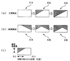
- FIG. 4A schematically shows the normal catalyst, that is, the catalyst 30 without S poisoning
- FIG. 4A schematically shows the normal catalyst, that is, the catalyst 30 without S poisoning
- FIG. 4B schematically shows the catalyst 30 with S poisoning.
- . 4 (a) and 4 (b) both show the catalyst 30 in an oxygen-excess state, that is, a state in which oxygen is stored to the full oxygen storage capacity OSC.
- OSC full oxygen storage capacity
- the catalyst 30 in the normal state of FIG. 4A unburned components and the like (H 2 , HC, CO) flowing from the left side of the page are occluded as they flow into the catalyst 30. Oxygen can oxidize these components.
- the S-poisoned catalyst 30 in FIG. 4 (b) when the unburned components flowing in from the left side of the paper flow into the catalyst 30, the oxygen release rate is slow.
- FIGS. 5 and 6 are diagrams for explaining the difference in the presence or absence of S poisoning when the gas containing the catalyst changes from rich to lean. .
- This explanation of (2-b) is for “the air-fuel ratio sensor 42 output signal when there is S poisoning indicated by a solid line” and “when there is no S poisoning indicated by a broken line” for the part relating to the region B in FIG. The mechanism by which the difference between the output signal and the air / fuel ratio sensor 42 output signal ”occurs is described.
- FIG. 5 is a schematic enlarged view for explaining the vicinity of the region B in FIG.
- FIG. 6 is an image diagram of oxygen storage / release in the catalyst 30.
- FIG.6 (c) is the figure which summarized the said description about how to read Fig.6 (a) (b) typically.
- the vertical direction on the paper surface in FIG. 6 means the amount of oxygen adsorption
- the horizontal direction on the paper surface in FIG. 6 is the distance (position) in the axial direction of the catalyst 30, and the exhaust gas flows from left to right on the paper surface.
- the state in which the shape of the hatched portion changes indicates that oxygen adsorption flows downstream.
- the white ratio indicates the ratio of the portion where oxygen is not occluded (the amount of noble metal not adsorbing oxygen), and the hatched portion indicates the ratio of the portion where oxygen is occluded.
- the area ratio between the white color and the shaded area in the square represents the degree of oxygen storage (ratio) in the catalyst 30.
- the time when the ratio of the white part and the shaded part is the same is when the downstream side of the catalyst 30 is stoichiometric.
- oxygen is adsorbed on the catalyst at a ratio of more than half at the inlet portion of the catalyst 30, and the oxygen adsorption amount (that is, the oxygen adsorbed toward the downstream side of the exhaust passage along the axial direction of the catalyst). Occlusion amount) is decreasing.
- FIG. 6A schematically shows the state of the catalyst 30 (state X1A, state X2A, state X3A) at the respective times X1, X2, and X3 of the normal catalyst 30 shown in FIG. Shown in time series.
- X1A in FIG. 6 represents a state in which oxygen (shaded portion) disappears and a rich output appears in the air-fuel ratio sensor 42 in the normal catalyst.
- X2A in FIG. 6 represents a state in which the target A / F is switched to the lean A / F by active control and oxygen storage is progressing in the normal catalyst.
- FIG. 6 is a state in which the oxygen storage ratio in the catalyst 30 is exactly 50%, and the ratio between the portion that has stored oxygen and the portion that has not stored oxygen is equal.
- the output of the air-fuel ratio sensor 42 just matches the stoichiometric.
- the three squares in FIG. 6 (b) indicate the states of the catalyst 30 (state X1B, state X2B, state X3B) at the respective times X1, X2, and X3 shown in FIG. ) Schematically and in time series.
- X1B in FIG. 6 shows that the oxygen-occluded portion (hatched portion) remains even at the time of X1 in FIG.
- the area ratio between the white and the hatched portion in the square represents the oxygen storage degree (ratio) in the catalyst 30, and when the ratio between the white and the hatched portion is the same, the downstream of the catalyst 30. Is the time when becomes stoichiometric. Therefore, in the S-poisoned catalyst shown in FIG. 6 (b), the catalyst 30 is rapidly added so that the area ratio between the white and the shaded portion in the square becomes equal to the oxygen remaining in the stage of X1B. Will occlude oxygen. As a result, the downstream of the catalyst 30 immediately becomes stoichiometric at the stage X2B in FIG.
- the “output change speed from rich to stoichiometric after switching from rich to lean by active control” is relatively large (that is, converges to stoichiometric in a relatively short time)
- oxygen release It can be determined that the speed has decreased and S poisoning has occurred.
- the S poisoning degree of the catalyst 30 is estimated by calculating the “rich / lean area ratio” as described in the following specific calculation method. You can also
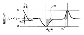
- FIG. 7 is a diagram for explaining a plurality of parameters (estimated parameters) related to the estimation of the degree of S poisoning of the catalyst 30 in the embodiment of the present invention.
- FIG. 7 shows the air-fuel ratio of “catalyst output A / F” detected by the air-fuel ratio sensor 42.
- estimated parameters p A , p B , p C , p D , and p E listed below are calculated from the output waveform of such an air-fuel ratio sensor 42.
- FIG. 7 illustrates VL, VR, Vos, Ta, and Tc, which are values necessary for calculating the estimation parameters p A , p B , p C , p D , and p E , respectively.
- the estimation parameters p A and p A calculated according to the switching control from lean to rich in the active control are respectively defined as follows. This is the estimated parameter obtained in accordance with the active control of the timing of the time t 1 of FIG.
- the estimation parameter “p A ” is the A / F change speed after the lean-to-rich switching control, and is defined by the following equation.
- VL is a peak value on the lean side in the sensor output waveform of FIG. Ta is the time from the lean side peak value to crossing the stoichiometry in the sensor output waveform of FIG.
- p A VL / Ta (1)
- the estimated parameter “p B ” is the stoichiometric overshoot amount after the lean ⁇ rich switching control, and is defined by the following equation.
- Vos is the size of the rich side peak width (vibration width) in the period from when it crosses the stoichiometry at time Ta and then swings toward the lean side and converges to stoichiometry.
- p B Vos (2)
- the estimation parameter p C calculated according to the switching control from rich to lean in the active control is defined as follows.
- This p C is an estimated parameter obtained according to the active control at the time t 2 in FIG. 3, and is an estimated parameter according to the rich-to-lean switching control opposite to the above-mentioned p A and p B. .
- the estimation parameter “p C ” the time or speed until the A / F becomes stoichiometric after the rich-to-lean switching control is used.
- p C is a value defined by the following formula (3) or (4).
- VR is a peak value on the lean side in the sensor output waveform of FIG.
- Tc is the time from the rich-side peak value to the stoichiometry in the sensor output waveform of FIG.
- When using time: p C Tc (3)
- speed: p C VR / Tc (4)
- the estimated parameters p A and p C are the A / F change speeds after the air-fuel ratio switching control between lean and rich.
- various numerical values representing how steep the change in A / F can be used.
- ) or the like may be applied.
- “time” is used to reflect the transition of the period of convergence to stoichiometry in the calculation, but “period” expressed by a crank angle or the like may be used.
- the estimated parameter p D which is calculated according to one reciprocation of the switching control until a rich via lean from rich, defined as follows.
- the p D is the estimated parameter obtained in accordance with the active control in the period from time t 2 in FIG. 3 to t 3.
- the estimation parameter “p D ” is an “output area ratio” from rich to lean to rich.
- the "Output area ratio” is defined by the ratio D R / D L of the area D R and the area D L shown in FIG.
- Area D R is the "area determined by integration of the rich output waveform”
- area D L is the "area determined by integration of the lean output waveform”. That is, the estimated parameters p D is defined by the following equation.
- V (rich) in the above equation (6) means an output in the rich region of the output voltage V of the air-fuel ratio sensor 40.
- V (lean) in the above equation (7) means an output in the lean region of the output voltage V of the air-fuel ratio sensor 40.
- V (rich), V (lean) respectively, rich output in the period from time t 2 to time t 3, a lean output.
- Tc (that is, the time from the rich side peak value to the stoichiometry in the sensor output waveform of FIG. 7) becomes relatively small due to the influence of the decrease in the oxygen release rate of the catalyst due to S poisoning.
- the catalyst deterioration determination OBD open loop control
- the following estimated parameter “p E ” can be used.
- the open loop control the A / F control for the gas containing the catalyst is performed regardless of the output value of the catalyst downstream sensor (in this embodiment, the air-fuel ratio sensor 42).
- the catalyst S poisoning state can also be estimated by monitoring the rich peak value (corresponding to VR in FIG. 7).
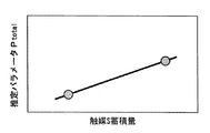
- FIG. 8 is a diagram for explaining a map for calculating the degree of S poisoning (catalyst S accumulation amount) of the catalyst 30 in the embodiment of the present invention.
- FIG. 8 shows a correlation between the estimated parameter Ptotal calculated by combining the plurality of estimated parameters described above and the catalyst S accumulation amount.
- this map is stored in advance by the catalyst poisoning estimation unit 66 in the ECU 60.
- the estimated parameter P total is calculated by the following equation.
- the estimated value of the S poisoning degree (catalyst S accumulation amount) of the catalyst 30 is calculated from the output of the air-fuel ratio sensor 42. be able to.
- FIG. 9 is a flowchart of a routine executed by the ECU in the catalyst poisoning detection apparatus for an internal combustion engine according to the embodiment of the present invention.
- the control process for realizing the technology for estimating the degree of catalyst poisoning described above can be executed on the ECU 60.
- the ECU 60 executes a process of determining whether or not a precondition for performing the catalyst deterioration detection is satisfied (step S100).
- the determination of the precondition is affirmative (Yes) when each of the following conditions is satisfied.
- a predetermined temperature T 0 for example, 500 ° C.
- the air-fuel ratio sensors 40 and 42 are activated (such as whether the sensor has reached the activation temperature). If the condition of step S100 is not satisfied, the current routine ends without performing catalyst deterioration detection.
- step S102 the ECU 60 then starts an active control process (step S102).
- the active control unit 62 executes the active control described in the above “active control and catalyst deterioration detection method based on the maximum oxygen storage amount Cmax”. Specifically, the ECU 60 switches the target A / F of the engine 10 to a step shape corresponding to the “catalyst-containing A / F” in the upper part of FIG. 3 and performs fuel injection control corresponding thereto. At this time, the value of lean A / F is 14.1, and the value of rich A / F is 15.1. That is, the width of the target A / F in the active control is set from 14.1 to 15.1.
- the ECU 60 starts a process for estimating the catalyst S state (step S104).
- the processing contents of this step are programmed in the catalyst poisoning estimation unit 66 so as to realize the contents described in the above-mentioned “technique for estimating the degree of catalyst poisoning”.
- the catalyst poisoning estimation unit 66 acquires the output of the air-fuel ratio sensor 42 according to the active control. This acquired output signal shows a waveform such as “catalyst output A / F” in FIG. 3.
- the catalyst poisoning estimation unit 66 executes a process of acquiring the values VL, VR, Vos, Ta, and Tc shown in FIG. 7 for the acquired waveform according to the calculation formulas (1) to (8) listed above.
- processing for calculating the estimation parameters p A , p B , p C , p D , and p E is executed. Thereafter, the catalyst poisoning estimation unit 66 calculates an estimated value of the catalyst S accumulation amount according to the above equation (9). Thereafter, the current routine ends.
- the degree of S poisoning of the catalyst 30 can be estimated by evaluating the output characteristics of the air-fuel ratio sensor 42.
- the Cmax calculation unit 64 in the ECU 60 appropriately executes a process of calculating the maximum oxygen storage amount Cmax, and the ECU 60 further performs the above-described “based on the maximum oxygen storage amount Cmax.
- the “determination process for determining that the catalyst 30 has deteriorated when the maximum oxygen storage amount Cmax is smaller than the reference value” according to the “catalyst deterioration detection method” is executed.
- the above estimation result of S poisoning is included in the routine including this determination process. For example, when it is estimated that S poisoning is caused by the routine of FIG.
- the catalyst based on the maximum oxygen storage amount Cmax is used.
- the result of the determination process of deterioration may be handled as if the accuracy is questionable.
- the ECU 60 may execute a process of determining whether or not to use the result of the catalyst deterioration determination process based on the maximum oxygen storage amount Cmax, depending on the presence / absence and amount of S poisoning.
- the catalyst 30 is the “catalyst” in the first invention
- the air-fuel ratio sensor 42 is the “catalyst downstream air-fuel ratio sensor” in the first invention
- the active control unit 62 corresponds to the “air-fuel ratio control unit” in the first invention
- the catalyst poisoning estimation unit 66 corresponds to the “air-fuel ratio control unit” in the first invention
- the “estimation unit” in the first invention corresponds to the “catalyst” in the eighth invention
- the air-fuel ratio sensor 42 corresponds to the “catalyst downstream air-fuel ratio detecting means” in the eighth invention. ing.
- the ECU 60 executes the process of step S102 of the routine of FIG.
- Ta, Vos, p A , and p B are calculated from the lean air-fuel ratio in the output of the catalyst downstream air-fuel ratio sensor according to the lean rich control in the second invention. This corresponds to the “length of the period until convergence to the air-fuel ratio or a parameter having a correlation with the length of the period”.
- Tc and p C is to converge from the rich air-fuel ratio to the stoichiometric air-fuel ratio at the output of the catalyst downstream air-fuel ratio sensor in accordance with "the rich lean control in the second aspect of the present invention Corresponds to a parameter having a correlation with the length of the period up to or the length of the period.
- the maps defining the characteristics shown in equations (1) to (9) and FIG. 8 stored in the ECU 60 correspond to the “predetermined function” in the third invention. is doing.
- the structure concerning said embodiment is equipped with the air fuel ratio sensor in the upstream and downstream of a catalyst, respectively.
- an O 2 sensor whose operation principle is an electromotive force method has hysteresis. Therefore, a small change necessary for this catalyst deterioration detection technology, that is, “downstream of the catalyst due to a change in the oxygen release rate of the catalyst due to poisoning”. It is impossible to detect “change in the stoichiometric convergence characteristic of the air-fuel ratio”.
- the limit current type air-fuel ratio sensor 42 can monitor such a change, and the air-fuel ratio sensor is preferable from the viewpoint of obtaining sufficient resolution.
- the hysteresis considered as a problem here is unique to the electromotive force sensor, and this hysteresis is extremely small in the air-fuel ratio sensor. This is because the limit current type gas sensor always reacts the gas to the limit because of its operating principle, and the gas has reacted completely inside the sensor element.
- Equation (9) all the estimation parameters p A , p B , p C , p D , and p E are used in Equation (9).
- the present invention is not limited to this.
- a part (one or more) of the estimation parameters p A , p B , p C , p D , and p E may be selected to create a P total calculation formula.
- w A , w B , w C , w D , and w E are weighting values (coefficients) and are values determined by adaptation. It is conceivable that the correlation between each parameter and the S accumulation amount varies depending on the intake air amount Ga and the engine speed NE. Further, it is conceivable that the correlation between each parameter and the amount of accumulated S changes depending on the configuration of the catalyst and the configuration of the engine. In consideration of such points, it is preferable to determine preferable weighting values for each of the fits, and these values can be different from each other depending on the fit result. Furthermore, it is preferable to perform functionalization, correction processing, and the like according to engine operating conditions such as Ga and NE, and operating states, with respect to the weighted values.
- the estimated parameter p E acquires the rich peak value during open loop control at an appropriate timing, it may be counted.
- P total may be defined by a function of only p A , p B , p C and p D without including p E.
- the catalyst poisoning estimation unit 66 in the ECU 60 compares the values of the respective estimated parameters p A , p B , p C , p D , and p E with predetermined reference values (determination values), respectively, so that S poisoning is performed. It may be determined whether or not the above has occurred.
- predetermined reference value “values of estimated parameters p A , p B , p C , p D , and p E calculated from sensor output characteristics when there is no S poisoning (that is, when normal) is used.
- step S104 of FIG. 9 the catalyst poisoning estimation unit 66 in the ECU 60 calculates at least one of the estimated parameters p A to p E and compares the calculated value with a predetermined value, You may perform the process which estimates the presence or absence and amount of poisoning of the catalyst 30.
- FIG. 9 the catalyst poisoning estimation unit 66 in the ECU 60 calculates at least one of the estimated parameters p A to p E and compares the calculated value with a predetermined value.
- Vos was used to determine the estimated parameter p A ⁇ p E, Ta, Tc, D R and D L are also respectively, based on comparison with a predetermined value, the poisoning of the catalyst 30 whether or the amount of It may be used for estimation.
- the catalyst poisoning estimation unit 66 in the ECU 60 determines the presence / absence and amount of the catalyst 30 based on the presence / absence of the overshoot Vos or the magnitude of the overshoot Vos (whether it is equal to or greater than a predetermined value). You may perform the process to estimate.
- the catalyst poisoning estimation unit 66 in the ECU 60 determines that “the length of the period until the convergence from lean A / F to stoichiometric” or “the length of the period from the lean side peak to crossing stoichiometric (in the embodiment, Ta ) " May be executed with a predetermined value. Further, the catalyst poisoning estimation unit 66 in the ECU 60 “the length of time until convergence from lean A / F to stoichiometric” or “the length of time until the stoichiometric value is first reached from the rich side peak” ( In the embodiment, a process of comparing Tc) with a predetermined value may be executed. D R and D L are similar. These may be combined, and the determination result may be weighted.
- the quantitative value of each estimated parameter is calculated, and the poisoning amount of the catalyst (specifically, the amount of accumulated catalyst S) is calculated.
- the degree of poison is not limited to the method for calculating the estimated value of the catalyst poisoning amount itself. For example, comparing one or more points in the sensor waveform with a predetermined value (one or more points in the sensor waveform in the absence of catalyst poisoning) and the difference Whether or not the catalyst is poisoned may be estimated based on whether or not a predetermined amount or more is recognized.
- the “catalyst deterioration detection method based on the maximum oxygen storage amount Cmax” is used for detecting the deterioration of the catalyst 30 of the engine 10.
- the present invention is not limited to such an embodiment, and the present invention can be implemented as an apparatus for detecting poisoning of a catalyst independently of detection of catalyst deterioration.
- the poisoning of the catalyst by the catalyst poisoning detection apparatus of the internal combustion engine according to the present invention when correcting or changing the control contents and operating conditions of the internal combustion engine according to the presence or absence of the catalyst poisoning or the amount of poisoning, the poisoning of the catalyst by the catalyst poisoning detection apparatus of the internal combustion engine according to the present invention.
- the detection result for can be used for this. Therefore, although catalyst deterioration detection can be given as one of the applications of the catalyst poisoning detection technique according to the present invention, the catalyst deterioration detection technique according to the present invention may be used for other applications.
Landscapes
- Engineering & Computer Science (AREA)
- Chemical & Material Sciences (AREA)
- Combustion & Propulsion (AREA)
- Mechanical Engineering (AREA)
- General Engineering & Computer Science (AREA)
- Chemical Kinetics & Catalysis (AREA)
- Electrical Control Of Air Or Fuel Supplied To Internal-Combustion Engine (AREA)
- Combined Controls Of Internal Combustion Engines (AREA)
- Exhaust Gas After Treatment (AREA)
Abstract
内燃機関における触媒の被毒を検出する触媒被毒検出装置であって、触媒下流空燃比センサと、空燃比制御部と、触媒の被毒についての推定を行う推定部とを備える。空燃比制御部は、理論空燃比に対してリッチであるリッチ空燃比とリーンであるリーン空燃比との間で触媒の上流側の排気ガスの空燃比を切り替えるように、リーン空燃比からリッチ空燃比へと排気ガスの空燃比を変化させるリーンリッチ制御とリッチ空燃比からリーン空燃比へと排気ガスの空燃比を変化させるリッチリーン制御とを行う。推定部は、リーンリッチ制御に応じた触媒下流空燃比センサの出力におけるリーン空燃比から理論空燃比へと収束するまでの間の出力値、または/およびリッチリーン制御に応じた触媒下流空燃比センサの出力におけるリッチ空燃比から理論空燃比へと収束するまでの間の出力値に基づいて、触媒の被毒についての推定を行う。
Description
この発明は、内燃機関の触媒被毒検出装置に関する。
従来、例えば、特開2003-97334号公報に開示されているように、触媒の上流と下流にそれぞれ排気ガスセンサを配置して、触媒の酸素吸蔵容量(OSC)を算出する構成を備えた内燃機関の触媒被毒検出装置が知られている。上記従来の触媒劣化検出装置においては、より具体的には、排気通路に上流側触媒と下流側触媒が配置され、両者の間に第1のO2センサが、後者の下流に第2のO2センサがそれぞれ配置されている。空燃比を強制的に振動させて上流側触媒の酸素吸蔵容量(OSC)を検出し、そのOSCが所定値より大きいか否かに基づいて上流側触媒の劣化を検出する。このような強制的な振動を実施する空燃比制御は、アクティブ制御とも称される。
上記特開2003-97334号公報にかかる触媒劣化検出装置は、触媒の上流と下流とに排気ガスセンサを設ける構成を開示しているものの、触媒の下流に配置する構成として実際の開示があるのは、いわゆるO2センサのみであり、空燃比センサではない。空燃比センサが排気ガス中の酸素濃度に応じてほぼリニアな出力を発することができるのに対して、O2センサは排気ガス中の酸素濃度が所定値を越える前後で大きく出力を変化させるセンサである。この種のO2センサを触媒下流に配置する構成としては、上記公報にかかるアクティブ制御技術や、空燃比制御においてサブフィードバック制御を行う技術などを含め、種々の構成が知られている。
本願発明者は、鋭意研究を行ったところ、触媒の下流に空燃比センサを設け、この触媒下流の空燃比センサの出力特性を評価することにより触媒の被毒を推定するという新規な技術を見出した。すなわち、触媒は、適量の酸素を吸蔵しておく能力(酸素吸蔵能力)を有しており、排気ガス中にHCやCOなどの未燃成分が含まれている場合は、吸蔵している酸素を用いてそれらの成分を酸化する。このような反応過程において触媒の酸素の吸蔵と放出はそれぞれある特定の速度(それぞれ、酸素吸蔵速度、酸素放出速度)で進むものである。一方、触媒の被毒により酸素放出速度の低下が起きることが知られている。具体的には、燃料中の硫黄成分等に起因した触媒のS被毒(硫黄被毒)が起きると、これらの速度のうち酸素放出速度が低下する。このように酸素放出速度を低下させる被毒が触媒に生じた場合には、その酸素放出速度低下の影響は、触媒下流の空燃比センサにおける「リーンまたはリッチからストイキへと収束する過程での空燃比の波形」に表れてくる。そこで、本願発明者は、この触媒下流の空燃比センサの出力に基づいて被毒による触媒劣化検出を行うという、新規な技術を見出した。
O2センサの機能、すなわち排気ガス中の酸素濃度が所定値を越える前後で大きく出力を変化させる機能は、上記従来の技術に用いられている公知の強制的な空燃比制御(公知のアクティブ制御)による酸素吸蔵容量測定のための機能や、上記従来の触媒劣化検出装置で要求されている機能を満たすことはできる。しかしながら、その一方で、上記のO2センサは、本願発明者が見出した新規な触媒劣化検出技術で必要となる、「被毒による触媒の酸素放出速度の変化に起因する、触媒下流空燃比のストイキ収束特性の変化」を検出することはできない。このような従来の技術水準のもとでは、「被毒による触媒の酸素放出速度の変化に起因する、触媒下流空燃比のストイキ収束特性の変化」を利用し被毒による触媒劣化検出を行うという技術や、そのような現象を前提として触媒下流の空燃比センサ出力をどのように評価すればよいか等についての技術も、何ら知られていない。
この発明は、上記のような課題を解決するためになされたもので、触媒下流に設けた空燃比センサの出力に基づいて、被毒による触媒の酸素放出速度の変化を利用して、良好な精度で触媒の被毒を検出することができる内燃機関の触媒被毒検出装置を提供することを目的とする。
第1の発明は、酸素吸蔵能を有する触媒が排気通路に設けられた内燃機関における触媒の被毒を検出する触媒被毒検出装置であって、触媒下流空燃比センサと、空燃比制御部と、前記触媒の被毒についての推定を行う推定部とを備えている。触媒下流空燃比センサは、内燃機関の排気通路における、前記排気通路に配置された触媒の下流の位置に設けられた空燃比センサである。空燃比制御部は、理論空燃比に対してリッチであるリッチ空燃比とリーンであるリーン空燃比との間で前記触媒の上流側の排気ガスの空燃比を切り替えるように、リーン空燃比からリッチ空燃比へと前記排気ガスの空燃比を変化させるリーンリッチ制御とリッチ空燃比からリーン空燃比へと前記排気ガスの空燃比を変化させるリッチリーン制御とを行う。推定部は、前記リーンリッチ制御に応じた前記触媒下流空燃比センサの出力におけるリーン空燃比から理論空燃比へと収束するまでの間の出力値、または/および前記リッチリーン制御に応じた前記触媒下流空燃比センサの出力におけるリッチ空燃比から理論空燃比へと収束するまでの間の出力値に基づいて、前記触媒の被毒についての推定を行う。
また、第2の発明は、第1の発明において、前記推定部は、次の二つの期間推定部のうち少なくとも一方を含む。一つ目の期間推定部は、前記リーンリッチ制御に応じた前記触媒下流空燃比センサの出力におけるリーン空燃比から理論空燃比へと収束するまでの期間の長さ又は前記期間の長さと相関を有するパラメータに基づいて、前記触媒の被毒の有無の推定または前記触媒の被毒の量の推定を行う。二つ目の期間推定部は、前記リッチリーン制御に応じた前記触媒下流空燃比センサの出力におけるリッチ空燃比から理論空燃比へと収束するまでの期間の長さ又は前記期間の長さと相関を有するパラメータに基づいて、前記触媒の被毒の有無の推定または前記触媒の被毒の量の推定を行う。
また、第3の発明は、第1または第2の発明において、前記推定部は、次の二つの推定演算部のうち少なくとも一方を含む。一つ目の推定演算部は、前記リーンリッチ制御に応じた前記触媒下流空燃比センサの出力におけるリーン空燃比から理論空燃比へと収束する間の出力値に基づいて、前記触媒下流空燃比センサの出力値と前記触媒の被毒との関係を定めた所定の関数に従って、前記触媒の被毒の有無の推定または前記触媒の被毒の量の推定を行う。二つ目の推定演算部は、前記リッチリーン制御に応じた前記触媒下流空燃比センサの出力におけるリッチ空燃比から理論空燃比へと収束する間の出力値に基づいて、前記触媒下流空燃比センサの出力値と前記触媒の被毒との関係を定めた所定の関数に従って、前記触媒の被毒の有無の推定または前記触媒の被毒の量の推定を行う。
また、第4の発明は、第3の発明において、前記推定部は、オーバーシュート算出部と、リーンリッチ挙動特性値算出部と、リッチリーン挙動特性値算出部と、面積差異算出部とのうち少なくとも2つの算出部を含んでいる。
オーバーシュート算出部は、前記リーンリッチ制御に応じた前記触媒下流空燃比センサの出力におけるリーン空燃比から理論空燃比へと収束する間の出力値のなかのリッチ空燃比側へのオーバーシュートの大きさを算出する。
リーンリッチ挙動特性値算出部は、前記リーンリッチ制御に応じた前記触媒下流空燃比センサの出力におけるリーン空燃比から理論空燃比へと収束する間の出力値に基づいて、前記理論空燃比への収束までの期間の長さ又は前記触媒下流空燃比センサの出力による空燃比変化の時間軸に対する傾きを算出する。
リッチリーン挙動特性値算出部は、前記リッチリーン制御に応じた前記触媒下流空燃比センサの出力におけるリッチ空燃比から理論空燃比へと収束する間の出力値に基づいて、前記理論空燃比への収束までの期間の長さ又は前記触媒下流空燃比センサの出力による空燃比変化の時間軸に対する傾きを算出する。
面積差異算出部は、前記空燃比制御部での制御によるリッチ空燃比とリーン空燃比の間の往復に応じた前記触媒下流空燃比センサの出力値に基づいて、リッチ空燃比領域における出力波形と理論空燃比とがなす領域の面積と、リーン空燃比領域における出力波形と理論空燃比とがなす領域の面積と、の差異を算出する。
そして、第4の発明は、第3の発明にかかる前記所定の関数が、前記オーバーシュート算出部で算出した前記オーバーシュートの大きさ、前記リーンリッチ挙動特性値算出部で算出した前記期間の長さ又は傾きの大きさ、前記リッチリーン挙動特性値算出部で算出した前記期間の長さ又は前記傾きの大きさ、および前記面積差異算出部で算出した前記差異からなる群から選択した2つ以上の値と、前記触媒の被毒蓄積量と、の間の関係を、前記2つ以上の値それぞれに対する所定の異なる重み付け係数を含むようにして定めた関数を、含んでいる。
オーバーシュート算出部は、前記リーンリッチ制御に応じた前記触媒下流空燃比センサの出力におけるリーン空燃比から理論空燃比へと収束する間の出力値のなかのリッチ空燃比側へのオーバーシュートの大きさを算出する。
リーンリッチ挙動特性値算出部は、前記リーンリッチ制御に応じた前記触媒下流空燃比センサの出力におけるリーン空燃比から理論空燃比へと収束する間の出力値に基づいて、前記理論空燃比への収束までの期間の長さ又は前記触媒下流空燃比センサの出力による空燃比変化の時間軸に対する傾きを算出する。
リッチリーン挙動特性値算出部は、前記リッチリーン制御に応じた前記触媒下流空燃比センサの出力におけるリッチ空燃比から理論空燃比へと収束する間の出力値に基づいて、前記理論空燃比への収束までの期間の長さ又は前記触媒下流空燃比センサの出力による空燃比変化の時間軸に対する傾きを算出する。
面積差異算出部は、前記空燃比制御部での制御によるリッチ空燃比とリーン空燃比の間の往復に応じた前記触媒下流空燃比センサの出力値に基づいて、リッチ空燃比領域における出力波形と理論空燃比とがなす領域の面積と、リーン空燃比領域における出力波形と理論空燃比とがなす領域の面積と、の差異を算出する。
そして、第4の発明は、第3の発明にかかる前記所定の関数が、前記オーバーシュート算出部で算出した前記オーバーシュートの大きさ、前記リーンリッチ挙動特性値算出部で算出した前記期間の長さ又は傾きの大きさ、前記リッチリーン挙動特性値算出部で算出した前記期間の長さ又は前記傾きの大きさ、および前記面積差異算出部で算出した前記差異からなる群から選択した2つ以上の値と、前記触媒の被毒蓄積量と、の間の関係を、前記2つ以上の値それぞれに対する所定の異なる重み付け係数を含むようにして定めた関数を、含んでいる。
また、第5の発明は、第1乃至第4の発明の何れか1つにおいて、前記推定部は、次の第1乃至第6の被毒推定部の少なくとも1つを含む。第1の被毒推定部は、前記リーンリッチ制御に応じた前記触媒下流空燃比センサの出力におけるリーン空燃比から理論空燃比へと収束する間の出力値のなかのリッチ空燃比側へのオーバーシュートの有無に基づいて、又は前記出力値におけるリッチ空燃比側へのオーバーシュートの大きさに基づいて、前記触媒の被毒についての推定を行うものである。第2の被毒推定部は、前記リーンリッチ制御に応じた前記触媒下流空燃比センサの出力におけるリーン空燃比から理論空燃比へと収束する間の出力値の、時間軸に対する前記触媒下流空燃比センサの出力に基づく空燃比変化の傾きに基づいて、前記触媒の被毒についての推定を行うものである。第3の被毒推定部は、前記リッチリーン制御に応じた前記触媒下流空燃比センサの出力に基づく空燃比におけるリッチ空燃比から理論空燃比への収束の過程での、時間軸に対する前記触媒下流空燃比センサの出力に基づく空燃比変化の傾きに基づいて、前記触媒の被毒についての推定を行うものである。第4の被毒推定部は、前記空燃比制御部での制御によるリッチ空燃比とリーン空燃比の間での往復に応じた前記触媒下流空燃比センサの出力に基づく空燃比における、リッチ空燃比領域における波形と理論空燃比とがなす領域の面積に基づいて、前記触媒の被毒についての推定を行うものである。第5の被毒推定部は、前記空燃比制御部での制御によるリッチ空燃比とリーン空燃比の間での往復に応じた前記触媒下流空燃比センサの出力に基づく空燃比における、リーン空燃比領域における波形と理論空燃比とがなす領域の面積に基づいて、前記触媒の被毒についての推定を行うものである。第6の被毒推定部は、前記空燃比制御部での制御によるリッチ空燃比とリーン空燃比の間での往復に応じた前記触媒下流空燃比センサの出力に基づく空燃比における、リッチ空燃比領域における波形と理論空燃比とがなす領域の面積と、リーン空燃比領域における波形と理論空燃比とがなす領域の面積と、の差異に基づいて、前記触媒の被毒についての推定を行うものである。
また、第6の発明は、第1乃至第5の発明の何れかにおいて、前記空燃比制御部は、オープンループ制御により空燃比制御を実施するオープンループ空燃比制御部を含んでおり、前記推定部が、前記オープンループ制御におけるリッチ空燃比制御中のリッチピーク値に基づいて、前記触媒の被毒についての推定を行う。
また、第7の発明は、第1乃至第6の発明の何れかにおいて、前記推定部は、次の2つの被毒推定部のうち少なくとも一方を含んでいる。一つ目の被毒推定部は、前記リーンリッチ制御に応じた前記触媒下流空燃比センサの出力におけるリーン空燃比から理論空燃比へと収束する間の前記出力値と、所定の値との比較に基づいて、前記触媒の被毒の有無の推定または前記触媒の被毒の量の推定を行うものである。二つ目の被毒推定部は、前記リッチリーン制御に応じた前記触媒下流空燃比センサの出力におけるリッチ空燃比から理論空燃比へと収束する間の前記出力値と、所定の値との比較に基づいて、前記触媒の被毒の有無の推定または前記触媒の被毒の量の推定を行うものである。
第8の発明は、酸素吸蔵能を有する触媒が排気通路に設けられた内燃機関における触媒の被毒を検出する触媒被毒検出装置であって、触媒下流空燃比検知手段と、アクティブ制御手段と、前記触媒の被毒についての推定を行う推定手段とを備えている。触媒下流空燃比検知手段は、内燃機関の排気通路に配置された触媒の下流の位置の排気ガスの空燃比の値を検知する。アクティブ制御手段は、理論空燃比に対してリッチであるリッチ空燃比とリーンであるリーン空燃比との間で前記触媒の上流側の排気ガスの空燃比を切り替えるアクティブ制御を行う。推定手段は、前記アクティブ制御に応じたリーン空燃比から理論空燃比へと収束するまでの間の前記排気ガスの空燃比の値、または/および前記アクティブ制御に応じたリッチ空燃比から理論空燃比へと収束するまでの間の前記排気ガスの空燃比の値に基づいて、前記触媒の被毒量に応じた前記触媒の酸素放出速度の変化の関係および前記触媒の酸素放出速度に応じた排気ガス空燃比の波形の変化の関係を利用して、前記触媒の被毒についての推定を行う。
また、第9の発明は、内燃機関の触媒劣化検出装置であって、
第1乃至8の発明のいずれか1つにかかる内燃機関の触媒被毒検出装置と、
前記触媒被毒検出装置による触媒についての被毒の推定の結果を算入して、内燃機関の触媒の劣化を検出する手段と、
を備えることを特徴とする。
第1乃至8の発明のいずれか1つにかかる内燃機関の触媒被毒検出装置と、
前記触媒被毒検出装置による触媒についての被毒の推定の結果を算入して、内燃機関の触媒の劣化を検出する手段と、
を備えることを特徴とする。
触媒の酸素放出速度を低下させる触媒被毒が生じた場合に、その被毒量に応じて触媒の酸素放出速度が低下する。その酸素放出速度の変化の影響が、触媒下流におけるリーンまたはリッチから理論空燃比へ収束するまでの空燃比の挙動に表れる。
そこで、第1の発明によれば、空燃比センサによりこのような触媒の酸素放出速度変化の影響を検出できる点を利用して、良好な精度で触媒の被毒を検出することができる。
そこで、第1の発明によれば、空燃比センサによりこのような触媒の酸素放出速度変化の影響を検出できる点を利用して、良好な精度で触媒の被毒を検出することができる。
第2の発明によれば、触媒下流の空燃比挙動のうち、触媒下流の空燃比センサの出力におけるリーン空燃比から理論空燃比へと収束するまでの期間の長さに基づいて、触媒の被毒を検出することができる。
第3の発明によれば、空燃比センサの出力値を用いて所定の関数に従った演算を行うことにより、触媒の被毒の有無の推定または触媒の被毒の量の推定を行うことができる。
第4の発明によれば、空燃比センサの出力値から2つ以上のパラメータを算出して、これらのパラメータに対して重み付けを伴った計算を行うことができる。これにより、良好な精度で、触媒の被毒を検出することができる。
第5の発明によれば、触媒下流の空燃比挙動の波形から特定できる各種パラメータを、触媒の被毒の推定に利用することができる。
第6の発明によれば、リッチA/F制御中のリッチピーク値と酸素放出速度との間に相関がある点を利用して、触媒の被毒についての推定を行うことができる。
第7の発明によれば、空燃比センサの出力値を所定の値と比較することにより、触媒の被毒の有無の推定または触媒の被毒の量の推定を行うことができる。
第8の発明によれば、触媒下流の空燃比に触媒の酸素放出速度変化の影響が現れる点を利用して、良好な精度で触媒の被毒を検出することができる。
第9の発明によれば、触媒下流の空燃比センサの出力値に基づく高精度な触媒被毒推定の結果を算入して、内燃機関の触媒の劣化を判断することができる。
実施の形態.
[実施の形態の構成]
図1は、本発明の実施の形態にかかる内燃機関の触媒被毒検出装置の構成を、これが適用される内燃機関の構成の一部とともに示す図である。本実施の形態の制御装置が適用される内燃機関は自動車用の内燃機関であり、より具体的には、予混合燃焼式の4ストローク1サイクルレシプロエンジンである。本実施の形態の触媒劣化検出装置は、そのような内燃機関の運転を総合制御するECU(Electronic Control Unit)の一つの機能として実現される。
[実施の形態の構成]
図1は、本発明の実施の形態にかかる内燃機関の触媒被毒検出装置の構成を、これが適用される内燃機関の構成の一部とともに示す図である。本実施の形態の制御装置が適用される内燃機関は自動車用の内燃機関であり、より具体的には、予混合燃焼式の4ストローク1サイクルレシプロエンジンである。本実施の形態の触媒劣化検出装置は、そのような内燃機関の運転を総合制御するECU(Electronic Control Unit)の一つの機能として実現される。
(エンジンおよびシステムの構成)
以下、内燃機関10(以下、単に「エンジン10」と称す)の具体的構成について説明する。ただし各構成の図示は省略する。エンジン10は、内部にピストンを有し、このピストンはクランク機構を介してクランクシャフトと接続されている。クランクシャフトの近傍には、クランク角センサが設けられている。クランク角センサは、クランクシャフトの回転角度(以下「クランク角」という。)CAを検出するように構成されている。シリンダブロック上部にはシリンダヘッドが組み付けられており、ピストン上面からシリンダヘッドまでの空間は燃焼室を形成している。シリンダヘッドには、燃焼室内の混合気に点火する点火プラグが設けられている。
以下、内燃機関10(以下、単に「エンジン10」と称す)の具体的構成について説明する。ただし各構成の図示は省略する。エンジン10は、内部にピストンを有し、このピストンはクランク機構を介してクランクシャフトと接続されている。クランクシャフトの近傍には、クランク角センサが設けられている。クランク角センサは、クランクシャフトの回転角度(以下「クランク角」という。)CAを検出するように構成されている。シリンダブロック上部にはシリンダヘッドが組み付けられており、ピストン上面からシリンダヘッドまでの空間は燃焼室を形成している。シリンダヘッドには、燃焼室内の混合気に点火する点火プラグが設けられている。
エンジン10のシリンダヘッドは、燃焼室と連通する吸気ポートを備え、この吸気ポートと燃焼室の接続部には吸気バルブが設けられている。吸気ポートには吸気通路が接続されており、吸気通路には吸気ポートの近傍に燃料を噴射するインジェクタが設けられている。なお、燃焼室内に直接燃料を噴射する直噴インジェクタを備えるものであっても良い。
インジェクタの上流にはスロットルバルブが設けられている。スロットルバルブは、スロットルモータにより駆動される電子制御式のバルブである。スロットルバルブは、アクセル開度センサにより検出されるアクセル開度AAに基づいて駆動されるものである。スロットルバルブの近傍にはスロットル開度を検出するスロットル開度センサが設けられている。スロットルバルブの上流には、熱線式のエアフロメータが設けられている。エアフロメータは吸入空気量Gaを検出するように構成されている。エアフロメータの上流にはエアクリーナが設けられている。
インジェクタの上流にはスロットルバルブが設けられている。スロットルバルブは、スロットルモータにより駆動される電子制御式のバルブである。スロットルバルブは、アクセル開度センサにより検出されるアクセル開度AAに基づいて駆動されるものである。スロットルバルブの近傍にはスロットル開度を検出するスロットル開度センサが設けられている。スロットルバルブの上流には、熱線式のエアフロメータが設けられている。エアフロメータは吸入空気量Gaを検出するように構成されている。エアフロメータの上流にはエアクリーナが設けられている。
エンジン10のシリンダヘッドは、燃焼室と連通する排気ポートを備えている。排気ポートと燃焼室との接続部には排気バルブが設けられている。排気ポートには排気通路20が接続されている。排気通路20には、排気ガスを浄化する三元触媒(S/C)30(以下、単に「触媒30」という)が設けられている。排気通路20における触媒30の上流位置には、限界電流式の空燃比センサ40が設けられている。また、排気通路20における触媒30の下流位置にも、限界電流式の空燃比センサ42が設けられている。排気通路における空燃比センサ42の下流には、さらに、三元触媒32(以下、単に「触媒32」という)が設けられている。空燃比センサ40、42は、ともに、ECU60に接続している。
将来のエミッション規制の強化、OBD規制の強化、触媒貴金属の低減に伴い、制御性、ロバスト性の高い空燃比制御システムが求められている。この要求に対しては、三元触媒(S/C)の前後に空燃比センサ(例えば限界電流式空燃比センサ)を配置したシステムが将来的に有望である。本実施形態は、このような触媒前後にそれぞれ空燃比センサを配置した空燃比制御システムにおいて、本発明に係る空燃比センサの出力処理技術を適用するものである。
将来のエミッション規制の強化、OBD規制の強化、触媒貴金属の低減に伴い、制御性、ロバスト性の高い空燃比制御システムが求められている。この要求に対しては、三元触媒(S/C)の前後に空燃比センサ(例えば限界電流式空燃比センサ)を配置したシステムが将来的に有望である。本実施形態は、このような触媒前後にそれぞれ空燃比センサを配置した空燃比制御システムにおいて、本発明に係る空燃比センサの出力処理技術を適用するものである。
図1に示すように、本実施形態にかかるエンジン10には、制御装置としてのECU(Electronic Control Unit)60が備えられている。ECU60の出力側には、点火プラグ、インジェクタ、スロットルモータ等が接続されている。ECU60の入力側には、冷却水温センサ、クランク角センサ、アクセル開度センサ、スロットル開度センサ、エアフロメータ、空燃比センサ等が接続されている。ECU60は、クランク角センサの出力に基づいて、機関回転数NEを算出する。また、ECU60は、アクセル開度センサにより検出されるアクセル開度AA等に基づいて、機関負荷KLを算出する。ECU60は、機関回転数NEや機関負荷KL等に基づいて、燃料噴射量を決定する。このように、ECU60は、エンジンの運転情報をセンサ系統により検出しつつ、各アクチュエータを駆動し、運転制御を実行する。
ECU60は、上記のごときエンジン制御部のほか、図1に示すように、アクティブ制御部62、Cmax算出部64および触媒被毒推定部66を供えている。アクティブ制御部62は、筒内に供給される混合気の目標空燃比を制御することで、触媒上流の排気空燃比を強制的に燃料リーン側(以下「リーン側」と略する。)と燃料リッチ側(以下「リッチ側」と略する。)との間で交互に切り換える制御(「アクティブ制御」とも称される)を実行することができる。Cmax算出部64は、後述するように、アクティブ制御部62によるアクティブ制御に応じた空燃比センサ40の出力値に基づいて、最大酸素吸蔵量Cmaxの値を算出することができる。触媒被毒推定部66は、後述する実施の形態にかかる「触媒の被毒度合の推定技術」を実現する処理を実行するための制御部である。
(空燃比センサのセンサ素子部の構成)
図2は、本発明の実施の形態にかかる内燃機関の触媒被毒検出装置における、空燃比センサ40、42のセンサ素子部50を示す断面図である。センサ素子部50は、検出素子51としての固体電解質層を有している。固体電解質層51は、部分安定化ジルコニアよりなり、酸素イオン導電性を有する。固体電解質層51の一面には、計測電極52が設けられている。また、固体電解質層51の他面には、大気側電極(「基準ガス側電極」ともいう。)53が設けられている。これらの計測電極52及び大気側電極53は、ともに白金等よりなり、リード58a,58bを介してECU60にそれぞれ接続されている。
図2は、本発明の実施の形態にかかる内燃機関の触媒被毒検出装置における、空燃比センサ40、42のセンサ素子部50を示す断面図である。センサ素子部50は、検出素子51としての固体電解質層を有している。固体電解質層51は、部分安定化ジルコニアよりなり、酸素イオン導電性を有する。固体電解質層51の一面には、計測電極52が設けられている。また、固体電解質層51の他面には、大気側電極(「基準ガス側電極」ともいう。)53が設けられている。これらの計測電極52及び大気側電極53は、ともに白金等よりなり、リード58a,58bを介してECU60にそれぞれ接続されている。
また、固体電解質層51の一面には、多孔質拡散抵抗層54が形成されている。多孔質拡散抵抗層54は、計測電極52を覆い、かつ、該計測電極52に排気ガスを導入するためのガス透過層54aと、排気ガスの透過を抑制するガス遮断層54bとを有している。これらのガス透過層54a及びガス遮断層54bは、アルミナやジルコニア等のセラミックスよりなり、平均孔径や気孔率が互いに相違している。
固体電解質層51の他面には、大気導入ダクト55が形成されている。大気導入ダクト55は、上部に大気室(「基準ガス室」ともいう。)56を有している。この大気室56内に上記大気側電極53が配置されている。大気導入ダクト55は、アルミナ等の高熱伝導性セラミックスよりなる。大気導入ダクト55の下面には、ヒータ57が設けられている。ヒータ57は、通電により発熱する複数の発熱体57aと、該発熱体57aを覆う絶縁層57bとを有している。発熱体57aは、リード58cを介してECU60に接続されている。
このような構成を有するセンサ素子部50は、酸素濃度を直線的特性にて検出することができ、酸素濃度に応じた臨界電流をECU60に出力し得る。この空燃比センサ出力(臨界電流)は、排気ガスの空燃比と相関を有している。具体的には、排気ガスの空燃比がリーン側になるほど臨界電流は増大し、排気ガスの空燃比がリッチ側になるほど臨界電流は減少する。
なお、一般に、空燃比センサ40、42から取り出されたセンサ出力信号は、所定の信号処理が施された上で、ECU60での制御処理に用いられる。この信号処理はいわゆるLPF、HPFなどのバンドパスフィルタによる周波数信号処理等を含み、そのような信号処理の機能はECU60上に搭載されたりあるいは他の演算処理装置にて実現される。
[実施の形態の動作]
図3乃至図9は、本発明の実施の形態にかかる内燃機関の触媒被毒検出装置の動作について説明するための図である。以下の順に各項目についてそれぞれ説明を行う。
・アクティブ制御、および最大酸素吸蔵量Cmaxに基づく触媒劣化検出法
・触媒の被毒度合の推定技術
図3乃至図9は、本発明の実施の形態にかかる内燃機関の触媒被毒検出装置の動作について説明するための図である。以下の順に各項目についてそれぞれ説明を行う。
・アクティブ制御、および最大酸素吸蔵量Cmaxに基づく触媒劣化検出法
・触媒の被毒度合の推定技術
(アクティブ制御、および最大酸素吸蔵量Cmaxに基づく触媒劣化検出法)
図1のシステムによれば、触媒上流の排気空燃比をリッチ側(又はリーン側)からリーン側(又はリッチ側)に強制的に変化させてから触媒下流の酸素センサ出力が変化(反転)するまでの時間に、触媒30に流入する排気ガスの酸素過不足量を演算することで、触媒30の最大酸素吸蔵量Cmaxを算出することができる。すなわち、アクティブ制御を実行することにより、触媒30の最大酸素吸蔵量Cmaxを算出することができる。
図1のシステムによれば、触媒上流の排気空燃比をリッチ側(又はリーン側)からリーン側(又はリッチ側)に強制的に変化させてから触媒下流の酸素センサ出力が変化(反転)するまでの時間に、触媒30に流入する排気ガスの酸素過不足量を演算することで、触媒30の最大酸素吸蔵量Cmaxを算出することができる。すなわち、アクティブ制御を実行することにより、触媒30の最大酸素吸蔵量Cmaxを算出することができる。
図3を参照して、触媒の最大酸素吸蔵量Cmaxの算出方法について説明する。詳細には、図3の上段の「触媒入りA/F」は、触媒30の上流における排気ガスの目標A/Fに相当している。この「触媒入りA/F」が実現されるようにECU60での空燃比制御(エンジン10の目標A/Fの制御、燃料噴射量制御)がなされ、排気ガスは触媒30に流れ込み、その排気ガスの酸素濃度に応じた出力信号を空燃比センサ40が出力する。なお、本実施形態では、リーンA/Fの値を14.1とし、リッチA/Fの値を15.1とする。つまり、アクティブ制御における目標A/Fの幅を、14.1から15.1とする。
図3の下段の「触媒出A/F」は、触媒30下流の空燃比センサ42の出力波形を示している。ただし、図3の下段において、実線は「S被毒(すなわち硫黄被毒)が生じている状態」の信号波形を示しており、破線の信号波形は「S被毒が無い状態」の信号波形を示している。
図3の下段の「触媒出A/F」は、触媒30下流の空燃比センサ42の出力波形を示している。ただし、図3の下段において、実線は「S被毒(すなわち硫黄被毒)が生じている状態」の信号波形を示しており、破線の信号波形は「S被毒が無い状態」の信号波形を示している。
図3の時刻t0においては、触媒30が有する酸素吸蔵能力を飽和させるべく、図3の「触媒入りA/F」に示すように、筒内(燃焼室内)に供給される混合気の目標A/Fがリーン側目標値に設定されている。この状態では、筒内から酸素を含むリーンな排気ガスが排出される。また、触媒30にはリーンな排気ガスが流入するため、この排気ガス中の過剰な酸素が触媒30に吸蔵される。触媒30の酸素吸蔵能力が飽和していない間は、触媒30からリーンな排気ガスは吹き抜けてこない。
その後、触媒30の酸素吸蔵能力が飽和すると、触媒30からリーンな排気ガスが吹き抜けてくる。このため、空燃比センサ42の出力がリーンを示す。空燃比センサ42の出力が所定のリーン判定値に達すると、図3の「触媒入りA/F」に示すように、目標A/FがリーンA/FからリッチA/Fへと切り換えられる。図3においては、時刻t1がその時期に相当している。これにより、筒内からリッチな排気ガスが排出され、空燃比センサ40の出力がリッチを示す。このリッチな排気ガスが触媒30に流入すると、排気ガス中の還元剤により、触媒30に吸蔵された酸素が還元・放出される。この制御に応じて、空燃比センサ42の出力が、図3の領域Aのようにリーンからストイキへと収束するように変化する。
その後、触媒30に吸蔵された酸素が消費されると、触媒30からリッチな排気ガスが吹き抜けてくる。このため、触媒30下流の空燃比センサ42の出力が、リッチを示すように徐々に低くなる。この様子が、図3における領域Bに示されており、リッチからストイキへと収束するように空燃比センサ42の出力が変化している。
領域Bで記したセンサ出力のリッチ側変化の過程で、空燃比センサ42の出力が、所定のリッチ判定値に達する。そうすると、触媒30に酸素を吸蔵させるべく、図3の上段「触媒入りA/F」に示すように、アクティブ制御によって目標A/FがリッチA/FからリーンA/Fへと切り換えられる。図3においては、時刻t2がその時期に相当している。
領域Bで記したセンサ出力のリッチ側変化の過程で、空燃比センサ42の出力が、所定のリッチ判定値に達する。そうすると、触媒30に酸素を吸蔵させるべく、図3の上段「触媒入りA/F」に示すように、アクティブ制御によって目標A/FがリッチA/FからリーンA/Fへと切り換えられる。図3においては、時刻t2がその時期に相当している。
この一連の処理の流れは、時刻t1の時点において触媒30が酸素吸蔵容量OSC一杯に酸素を吸蔵しているところから、その後リッチ側に目標A/Fが切り替えられて、触媒30内の酸素が使い果たされることで時刻t2を迎える。つまり、時刻t1から時刻t2までの間において空燃比センサ40が示したリッチ側出力を積分した値は、時刻t1から時刻t2までの間に触媒30から放出された酸素量に相当している。リッチに設定された排気ガス中の不足酸素量を時刻t1から時刻t2まで積算することで、触媒30の放出酸素量を求めることができる。
時刻t2において目標A/Fがリーン側目標値に設定されると、筒内からリーンな排気ガスが排出されるようになる。その結果、触媒30上流の空燃比センサ40の出力がリーンを示す。リーンな排気ガスが触媒30に流入すると、排気ガス中の過剰な酸素が触媒30に吸蔵される。触媒30に酸素が吸蔵されている間は、触媒30からリーンな排気ガスは吹き抜けてこない。
その後、触媒30に酸素吸蔵容量OSC一杯の酸素が吸蔵されて、触媒30の酸素吸蔵能力が飽和すると、触媒30からリーンな排気ガスが吹き抜けてくる。このため、空燃比センサ42の出力がリーン側に変化する。空燃比センサ42の出力が所定のリーン判定値に達すると、図3の冗談「触媒入りA/F」に示すように、アクティブ制御により目標A/Fがリッチ側目標値に切り換えられる。図3においては、時刻t3がその時期に相当している。
その後、触媒30に酸素吸蔵容量OSC一杯の酸素が吸蔵されて、触媒30の酸素吸蔵能力が飽和すると、触媒30からリーンな排気ガスが吹き抜けてくる。このため、空燃比センサ42の出力がリーン側に変化する。空燃比センサ42の出力が所定のリーン判定値に達すると、図3の冗談「触媒入りA/F」に示すように、アクティブ制御により目標A/Fがリッチ側目標値に切り換えられる。図3においては、時刻t3がその時期に相当している。
この一連の処理の流れは、時刻t2の時点において触媒30が酸素を使い果たした状態から、その後リーン側に目標A/Fが切り替えられて、触媒30内に酸素吸蔵容量OSC一杯の酸素が吸蔵されることで時刻t3を迎える。つまり、時刻t2から時刻t3までの間において空燃比センサ40が示したリーン側出力を積分した値は、時刻t2から時刻t3までの間に触媒30に吸蔵された酸素量に相当している。リーンに設定された排気ガス中の過剰酸素量を時刻t2から時刻t3まで積算することで、触媒30の吸蔵酸素量を求めることができる。
このような制御を所定回数繰り返して放出酸素量と吸蔵酸素量を所定数求めて平均することで、触媒30の最大酸素吸蔵量Cmaxを求めることができる。この最大酸素吸蔵量Cmaxが基準値よりも小さい場合に、触媒30が劣化していると判断することができる。
(触媒の被毒度合の推定技術)
図3乃至9は、本発明の実施の形態にかかる内燃機関の触媒被毒検出装置において使用される、触媒の被毒度合の推定技術を説明するための図である。
図3乃至9は、本発明の実施の形態にかかる内燃機関の触媒被毒検出装置において使用される、触媒の被毒度合の推定技術を説明するための図である。
先ず、本実施形態にかかる、触媒の被毒度合の推定技術の概要について説明する。
本実施形態にかかる被毒度合の推定技術は、「触媒の酸素放出速度を低下させる触媒被毒」が生じた場合に、その影響の度合を推定することができる。具体的には、触媒の下流に空燃比センサを設け、この触媒下流の空燃比センサの出力特性を評価することにより、「触媒の酸素放出速度を低下させる触媒被毒」としてのS被毒(すなわち硫黄被毒)を対象にして、被毒の度合を推定する。
すなわち、触媒30は、適量の酸素を吸蔵しておく能力(酸素吸蔵能力)を有しており、排気ガス中にHCやCOなどの未燃成分が含まれている場合は、吸蔵している酸素を用いてそれらの成分を酸化する。このような反応過程において触媒30の酸素の吸蔵と放出はそれぞれある特定の速度(それぞれ、酸素吸蔵速度、酸素放出速度)で進むものであるが、S被毒が起きるとこれらの速度のうち酸素放出速度が低下する。この酸素放出速度低下の影響は、触媒30下流の空燃比センサ42における「リーンまたはリッチからストイキへと収束する過程での空燃比の波形」に表れてくる。この様子が、図3の「触媒出A/F」の実線と破線との比較により明らかにされている。図3に示すアクティブ制御中の空燃比センサ42出力において、リッチからストイキへと収束する速度やリーンからストイキへと収束する速度などが、S被毒発生の前後において異なっている。この相違(変化)は、S被毒発生時のほうが、ストイキへと向かう変化が急であり、ストイキへと収束する時期が早いというものである。触媒30の下流に空燃比センサ42を配置した構成によれば、そのような変化を十分な分解能により微小な相違(変化)も含めて検出することができる。そこで、触媒下流の空燃比センサ42の出力特性を評価することにより、触媒30のS被毒の度合を推定するのである。
本実施形態にかかる被毒度合の推定技術は、「触媒の酸素放出速度を低下させる触媒被毒」が生じた場合に、その影響の度合を推定することができる。具体的には、触媒の下流に空燃比センサを設け、この触媒下流の空燃比センサの出力特性を評価することにより、「触媒の酸素放出速度を低下させる触媒被毒」としてのS被毒(すなわち硫黄被毒)を対象にして、被毒の度合を推定する。
すなわち、触媒30は、適量の酸素を吸蔵しておく能力(酸素吸蔵能力)を有しており、排気ガス中にHCやCOなどの未燃成分が含まれている場合は、吸蔵している酸素を用いてそれらの成分を酸化する。このような反応過程において触媒30の酸素の吸蔵と放出はそれぞれある特定の速度(それぞれ、酸素吸蔵速度、酸素放出速度)で進むものであるが、S被毒が起きるとこれらの速度のうち酸素放出速度が低下する。この酸素放出速度低下の影響は、触媒30下流の空燃比センサ42における「リーンまたはリッチからストイキへと収束する過程での空燃比の波形」に表れてくる。この様子が、図3の「触媒出A/F」の実線と破線との比較により明らかにされている。図3に示すアクティブ制御中の空燃比センサ42出力において、リッチからストイキへと収束する速度やリーンからストイキへと収束する速度などが、S被毒発生の前後において異なっている。この相違(変化)は、S被毒発生時のほうが、ストイキへと向かう変化が急であり、ストイキへと収束する時期が早いというものである。触媒30の下流に空燃比センサ42を配置した構成によれば、そのような変化を十分な分解能により微小な相違(変化)も含めて検出することができる。そこで、触媒下流の空燃比センサ42の出力特性を評価することにより、触媒30のS被毒の度合を推定するのである。
以下、本実施形態にかかる、触媒の被毒度合の推定技術における具体的なメカニズムについて説明する。
(1)触媒のS被毒
燃料中のS(硫黄)が燃焼室を経て触媒に到達すると、触媒の貴金属に吸着し、排気ガス浄化能力を低下させる。このとき、リッチガスを酸化させる能力(酸素放出速度)が低下することが判明している。
(1)触媒のS被毒
燃料中のS(硫黄)が燃焼室を経て触媒に到達すると、触媒の貴金属に吸着し、排気ガス浄化能力を低下させる。このとき、リッチガスを酸化させる能力(酸素放出速度)が低下することが判明している。
(2)触媒劣化判定OBD(On-Board Diagnostic)およびアクティブ制御
触媒の劣化を判定するにあたり、アクティブ制御により触媒の最大酸素吸蔵量と最大酸素放出量をモニタ(計算)している場合には、触媒のS被毒が上記の酸素放出速度低下の影響が触媒30下流の空燃比センサ42の出力信号の挙動に影響を及ぼす。
触媒の劣化を判定するにあたり、アクティブ制御により触媒の最大酸素吸蔵量と最大酸素放出量をモニタ(計算)している場合には、触媒のS被毒が上記の酸素放出速度低下の影響が触媒30下流の空燃比センサ42の出力信号の挙動に影響を及ぼす。
(2-a)触媒入りガスがリーン→リッチへ変化するとき
図4は、触媒入りガスがリーン→リッチへ変化するときのS被毒の有無の差を説明するための図である。「触媒入りガス」とは、触媒30に流入する排気ガスを意味している。この(2-a)の説明は、図3の領域Aにかかる部分についての、「実線で示すS被毒ありの場合の空燃比センサ42出力信号」と「破線で示すS被毒なしの場合の空燃比センサ42出力信号」との間の差異が生ずるメカニズムを述べるものである。
図4(a)は、正常触媒つまりS被毒が無い状態の触媒30を模式的に示し、図4(b)は、S被毒が生じている状態の触媒30を模式的に示している。図4(a)(b)で示しているのは、両方とも、酸素過多状態つまり酸素吸蔵容量OSC一杯に酸素を吸蔵している状態の触媒30である。図4(a)の正常状態の触媒30によれば、紙面左方から流れ込んでくる未燃成分等(H2、HC、CO)が触媒30内に流入するのに応じて、吸蔵している酸素によりそれらの成分を酸化することができる。これに対し、図4(b)のS被毒状態の触媒30によれば、紙面左方から流れ込んでくる未燃成分等が触媒30内に流入してきたときに、酸素放出速度が遅いことが原因で、一部の成分についての酸化が間に合わずに吹き抜けが生じてしまう。このような吹き抜けの結果、正常時と比べて、触媒30下流の雰囲気がリーンからリッチ側(ストイキ)へと速やかに変化し、かつ、リッチ側への小さなオーバーシュートも発生してしまう。
そこで、ここで述べるS被毒度合の推定技術では、このような「触媒30下流の雰囲気がリーンからリッチ側(ストイキ)へと変化する速度」や、「リッチ側へのオーバーシュートの発生」をそれぞれ測定し、当該速度やオーバーシュートに基づいてS被毒度合を推定することにした。
図4は、触媒入りガスがリーン→リッチへ変化するときのS被毒の有無の差を説明するための図である。「触媒入りガス」とは、触媒30に流入する排気ガスを意味している。この(2-a)の説明は、図3の領域Aにかかる部分についての、「実線で示すS被毒ありの場合の空燃比センサ42出力信号」と「破線で示すS被毒なしの場合の空燃比センサ42出力信号」との間の差異が生ずるメカニズムを述べるものである。
図4(a)は、正常触媒つまりS被毒が無い状態の触媒30を模式的に示し、図4(b)は、S被毒が生じている状態の触媒30を模式的に示している。図4(a)(b)で示しているのは、両方とも、酸素過多状態つまり酸素吸蔵容量OSC一杯に酸素を吸蔵している状態の触媒30である。図4(a)の正常状態の触媒30によれば、紙面左方から流れ込んでくる未燃成分等(H2、HC、CO)が触媒30内に流入するのに応じて、吸蔵している酸素によりそれらの成分を酸化することができる。これに対し、図4(b)のS被毒状態の触媒30によれば、紙面左方から流れ込んでくる未燃成分等が触媒30内に流入してきたときに、酸素放出速度が遅いことが原因で、一部の成分についての酸化が間に合わずに吹き抜けが生じてしまう。このような吹き抜けの結果、正常時と比べて、触媒30下流の雰囲気がリーンからリッチ側(ストイキ)へと速やかに変化し、かつ、リッチ側への小さなオーバーシュートも発生してしまう。
そこで、ここで述べるS被毒度合の推定技術では、このような「触媒30下流の雰囲気がリーンからリッチ側(ストイキ)へと変化する速度」や、「リッチ側へのオーバーシュートの発生」をそれぞれ測定し、当該速度やオーバーシュートに基づいてS被毒度合を推定することにした。
(2-b)触媒入りガスがリッチ→リーンへ変化するとき
図5および図6は、触媒入りガスがリッチ→リーンへ変化するときのS被毒の有無の差を説明するための図である。この(2-b)の説明は、図3の領域Bにかかる部分についての、「実線で示すS被毒ありの場合の空燃比センサ42出力信号」と「破線で示すS被毒なしの場合の空燃比センサ42出力信号」との間の差異が生ずるメカニズムを述べるものである。
図5は、図3における領域B付近について説明するための模式的な拡大図である。
図6は、触媒30内の酸素吸蔵放出のイメージ図である。図6(c)は、図6(a)(b)の読み方についての上記説明を模式的にまとめた図である。図6の紙面上下方向は、酸素吸着量を意味し、図6の紙面左右方向は、触媒30の軸方向の距離(位置)であり、排気ガスは紙面の左から右へと流れる。図6のそれぞれの四角において、斜線部の形状が変化する様子は、酸素の吸着が下流側に流れていく様子を表している。白色の割合が、酸素が吸蔵されていない部分(酸素が吸着していない貴金属量)の割合を、斜線部の割合が、酸素が吸蔵された部分の割合を、それぞれ示している。四角中の白色と斜線部の面積比は、触媒30内の酸素吸蔵度合(割合)を表している。白色と斜線部の比率が同じであるときが、触媒30の下流がストイキとなっているときである。
図6(c)の場合には、触媒30の入口部分は半分以上の割合で触媒に酸素が吸着しており、触媒の軸方向に沿って排気通路下流側へいくほど酸素吸着量(つまり酸素吸蔵量)が減少している。以下、このような図6の図示方法を前提にしたうえで、図6(a)および(b)を詳細に説明する。
図5および図6は、触媒入りガスがリッチ→リーンへ変化するときのS被毒の有無の差を説明するための図である。この(2-b)の説明は、図3の領域Bにかかる部分についての、「実線で示すS被毒ありの場合の空燃比センサ42出力信号」と「破線で示すS被毒なしの場合の空燃比センサ42出力信号」との間の差異が生ずるメカニズムを述べるものである。
図5は、図3における領域B付近について説明するための模式的な拡大図である。
図6は、触媒30内の酸素吸蔵放出のイメージ図である。図6(c)は、図6(a)(b)の読み方についての上記説明を模式的にまとめた図である。図6の紙面上下方向は、酸素吸着量を意味し、図6の紙面左右方向は、触媒30の軸方向の距離(位置)であり、排気ガスは紙面の左から右へと流れる。図6のそれぞれの四角において、斜線部の形状が変化する様子は、酸素の吸着が下流側に流れていく様子を表している。白色の割合が、酸素が吸蔵されていない部分(酸素が吸着していない貴金属量)の割合を、斜線部の割合が、酸素が吸蔵された部分の割合を、それぞれ示している。四角中の白色と斜線部の面積比は、触媒30内の酸素吸蔵度合(割合)を表している。白色と斜線部の比率が同じであるときが、触媒30の下流がストイキとなっているときである。
図6(c)の場合には、触媒30の入口部分は半分以上の割合で触媒に酸素が吸着しており、触媒の軸方向に沿って排気通路下流側へいくほど酸素吸着量(つまり酸素吸蔵量)が減少している。以下、このような図6の図示方法を前提にしたうえで、図6(a)および(b)を詳細に説明する。
図6(a)の3つの四角はそれぞれ、正常な触媒30の図5に示す時期X1、X2、X3のそれぞれの時期における触媒30の状態(状態X1A、状態X2A、状態X3A)を模式的に時系列的に示している。図6のX1Aは、正常触媒において、酸素(斜線部)が無くなって空燃比センサ42にリッチ出力が現れる状態を表している。図6のX2Aは、正常触媒において、アクティブ制御で目標A/FがリーンA/Fに切り替わり酸素の吸蔵が進んでいる様子を表している。図6のX3Aは、触媒30内の酸素吸蔵割合がちょうど50%となり、酸素を吸蔵した部分と酸素を吸蔵していない部分との割合が等しくなった状態である。X3Aの時点において、図5のX3における破線の出力を見るとわかるように、ちょうど空燃比センサ42の出力がストイキに一致する。
一方、図6(b)の3つの四角はそれぞれ、S被毒状態の触媒30の図5に示す時期X1、X2、X3のそれぞれの時期における触媒30の状態(状態X1B、状態X2B、状態X3B)を模式的、時系列的に示している。図6のX1Bは、S被毒が生じた触媒において、酸素放出速度が遅いがために、図5のX1の時点でも酸素を吸蔵した部分(斜線部)が残っている様子を示している。前述したように、触媒30にS被毒が生じている状態では、酸素放出速度が遅いため、触媒30内の酸素を完全に使い切る前に触媒30下流の空燃比がリッチへと変化してしまうからである。X1AとX1Bを比較すると、酸素放出速度の低下により酸素残存状態が引き起こされていることがわかる。
一方、図6(b)の3つの四角はそれぞれ、S被毒状態の触媒30の図5に示す時期X1、X2、X3のそれぞれの時期における触媒30の状態(状態X1B、状態X2B、状態X3B)を模式的、時系列的に示している。図6のX1Bは、S被毒が生じた触媒において、酸素放出速度が遅いがために、図5のX1の時点でも酸素を吸蔵した部分(斜線部)が残っている様子を示している。前述したように、触媒30にS被毒が生じている状態では、酸素放出速度が遅いため、触媒30内の酸素を完全に使い切る前に触媒30下流の空燃比がリッチへと変化してしまうからである。X1AとX1Bを比較すると、酸素放出速度の低下により酸素残存状態が引き起こされていることがわかる。
図4のX1の時期に、アクティブ制御によりリッチからリーンへの目標A/Fの切り替えが行われる。その後は、触媒30内の酸素吸蔵量に応じて、触媒30下流の空燃比の値が変化することがわかっている。そのため、S被毒状態の触媒30では切替後の出力変化が急峻になる。
この点を、図6(b)と図6(a)との比較により、詳細に説明する。図6のX2B、X3Bは、S被毒が生じている触媒において、残存した酸素(斜線部)に加えてさらにリーン空燃比に制御された排気ガス中の酸素が触媒30に流れ込むことにより、酸素の吸蔵部分(斜線部)が増大している様子を表している。前述したように、図6では、四角中の白色と斜線部の面積比は触媒30内の酸素吸蔵度合(割合)を表しており、白色と斜線部の比率が同じときが、触媒30の下流がストイキとなるときである。従って、図6(b)に示すS被毒の触媒にあっては、X1Bの段階で残っていた酸素とあわせて、速やかに、四角中の白色と斜線部の面積比が等しくなるほどに触媒30が酸素を吸蔵することになる。その結果、図6のX2Bの段階において速やかに触媒30下流がストイキとなり、図5のX2の時期において実線の空燃比センサ42出力がストイキに収束している。つまり、S被毒状態の触媒30では、アクティブ制御によるリッチ→リーンへの切替後におけるリッチからストイキへの出力変化が急峻になっており、ストイキへの収束が相対的に迅速に完了するようになる。
そこで、図5に現れる空燃比センサ42の出力波形(出力特性)の相違を検出することで、S被毒の有無や度合を推定することができる。具体的には、「アクティブ制御によるリッチ→リーンへの切替後におけるリッチからストイキへの出力変化速度」が、相対的に大きい(つまり相対的に短時間でストイキに収束)であれば、酸素放出速度の低下が起きており、S被毒が生じていると判断できる。また、そのように短時間でストイキに収束する場合には、下記の具体的な計算方法で述べるように「リッチ、リーン面積比」を算出することにより、触媒30のS被毒度合を推定することもできる。
この点を、図6(b)と図6(a)との比較により、詳細に説明する。図6のX2B、X3Bは、S被毒が生じている触媒において、残存した酸素(斜線部)に加えてさらにリーン空燃比に制御された排気ガス中の酸素が触媒30に流れ込むことにより、酸素の吸蔵部分(斜線部)が増大している様子を表している。前述したように、図6では、四角中の白色と斜線部の面積比は触媒30内の酸素吸蔵度合(割合)を表しており、白色と斜線部の比率が同じときが、触媒30の下流がストイキとなるときである。従って、図6(b)に示すS被毒の触媒にあっては、X1Bの段階で残っていた酸素とあわせて、速やかに、四角中の白色と斜線部の面積比が等しくなるほどに触媒30が酸素を吸蔵することになる。その結果、図6のX2Bの段階において速やかに触媒30下流がストイキとなり、図5のX2の時期において実線の空燃比センサ42出力がストイキに収束している。つまり、S被毒状態の触媒30では、アクティブ制御によるリッチ→リーンへの切替後におけるリッチからストイキへの出力変化が急峻になっており、ストイキへの収束が相対的に迅速に完了するようになる。
そこで、図5に現れる空燃比センサ42の出力波形(出力特性)の相違を検出することで、S被毒の有無や度合を推定することができる。具体的には、「アクティブ制御によるリッチ→リーンへの切替後におけるリッチからストイキへの出力変化速度」が、相対的に大きい(つまり相対的に短時間でストイキに収束)であれば、酸素放出速度の低下が起きており、S被毒が生じていると判断できる。また、そのように短時間でストイキに収束する場合には、下記の具体的な計算方法で述べるように「リッチ、リーン面積比」を算出することにより、触媒30のS被毒度合を推定することもできる。
続いて、本実施形態にかかる、触媒の被毒度合の推定技術における、具体的な計算方法について説明する。先ず、触媒30のS被毒度合の推定にかかわる複数のパラメータ(推定パラメータ)を説明し、続いて、これらの推定パラメータを用いたS被毒度合推定値の計算方法を説明する。
図7は、本発明の実施の形態において、触媒30のS被毒度合の推定にかかわる複数のパラメータ(推定パラメータ)を説明するための図である。図7には、空燃比センサ42が検出する「触媒出A/F」の空燃比が示されている。本実施形態では、このような空燃比センサ42の出力波形から、下記に列挙する推定パラメータpA、pB、pC、pD、pEを算出する。図7には、推定パラメータpA、pB、pC、pD、pEを算出する上で必要な値であるVL、VR、Vos、Ta、Tcがそれぞれ図示されている。
まず、アクティブ制御における、リーンからリッチへの切替制御に応じて算出される推定パラメータpAとpAを、それぞれ、下記のとおりに定義する。これは、図3の時刻t1の時期におけるアクティブ制御に応じて得られる推定パラメータである。
推定パラメータ「pA」は、リーン→リッチ切替制御後のA/F変化速度であり、下記の式で定義される。VLは、図7のセンサ出力波形におけるリーン側のピーク値である。Taは、図7のセンサ出力波形においてリーン側ピーク値からストイキを横切るまでの時間である。
pA = VL/Ta ・・・(1)
推定パラメータ「pB」は、リーン→リッチ切替制御後のストイキオーバーシュート量であり、下記の式で定義される。Vosは、図7のセンサ出力波形において、時間Taでストイキを横切った後一端リーン側に振れてストイキに収束するまでの期間におけるリッチ側のピークの幅(振れ幅)の大きさである。
pB = Vos ・・・(2)
推定パラメータ「pA」は、リーン→リッチ切替制御後のA/F変化速度であり、下記の式で定義される。VLは、図7のセンサ出力波形におけるリーン側のピーク値である。Taは、図7のセンサ出力波形においてリーン側ピーク値からストイキを横切るまでの時間である。
pA = VL/Ta ・・・(1)
推定パラメータ「pB」は、リーン→リッチ切替制御後のストイキオーバーシュート量であり、下記の式で定義される。Vosは、図7のセンサ出力波形において、時間Taでストイキを横切った後一端リーン側に振れてストイキに収束するまでの期間におけるリッチ側のピークの幅(振れ幅)の大きさである。
pB = Vos ・・・(2)
一方、アクティブ制御における、リッチからリーンへの切替制御に応じて算出される推定パラメータpCを、下記のとおりに定義する。このpCは、図3の時刻t2の時期におけるアクティブ制御に応じて得られる推定パラメータであり、上記のpA、pBとは逆の、リッチ→リーン切替制御に応じた推定パラメータである。推定パラメータ「pC」としては、リッチ→リーン切替制御後の、A/Fがストイキとなるまでの時間または速度が用いられる。pCは、下記の式(3)又は(4)で定義される値である。VRは、図7のセンサ出力波形におけるリーン側のピーク値である。Tcは、図7のセンサ出力波形においてリッチ側ピーク値からストイキに至るまでの時間である。
時間を用いる場合: pC = Tc ・・・(3)
速度を用いる場合: pC = VR/Tc ・・・(4)
時間を用いる場合: pC = Tc ・・・(3)
速度を用いる場合: pC = VR/Tc ・・・(4)
なお、上記の推定パラメータpAおよびpCは、リーンとリッチの間の空燃比の切換制御後における、A/F変化速度である。推定パラメータpAおよびpCとしては、A/Fの変化がどれほどに急峻であるかを表す各種の数値を利用することができ、例えば、空燃比センサ出力波形のグラフにおける傾き(方向係数)、空燃比の変化率(|dVL/dt|あるいは|dVR/dt|)などをあてはめても良い。また、上記の計算では、ストイキへ収束する期間の推移を計算に反映させるために、「時間」を用いているが、クランク角等で表される「期間」を用いても良い。
さらに、アクティブ制御における、リッチからリーンを経てリッチとなるまでの一往復の切替制御に応じて算出される推定パラメータpDを、下記のとおりに定義する。このpDは、図3の時刻t2からt3までの期間におけるアクティブ制御に応じて得られる推定パラメータである。推定パラメータ「pD」は、リッチ→リーン→リッチまでの「出力面積比」である。ここでいう「出力面積比」とは、図7に示す面積DRと面積DLの比DR/DLで定義される。面積DRは、「リッチ出力波形の積分により求めた面積」であり、面積DLは、「リーン出力波形の積分により求めた面積」である。すなわち、推定パラメータpDは、下記の式で定義される。
pD = DR/DL ・・・(5)
 上記の式(6)のV(rich)とは、空燃比センサ40の出力電圧Vのうち、リッチ域における出力を意味している。上記の式(7)のV(lean)とは、空燃比センサ40の出力電圧Vのうち、リーン域における出力を意味している。図3との比較で説明すると、V(rich)、V(lean)は、それぞれ、時刻t2から時刻t3までの期間におけるリッチの出力、リーンの出力である。
S被毒による触媒の酸素放出速度低下の影響で、Tc(つまり図7のセンサ出力波形においてリッチ側ピーク値からストイキに至るまでの時間)は、相対的に小さくなる。これは、図3の「触媒出A/F」の実線(S被毒あり)と破線(S被毒無し)とを比べることによっても理解できる。Tcが相対的に小さければ、DRの値も相対的に小さくなる。従って、上記のpDの値に基づいて、S被毒度合を推定することができる。
pD = DR/DL ・・・(5)
S被毒による触媒の酸素放出速度低下の影響で、Tc(つまり図7のセンサ出力波形においてリッチ側ピーク値からストイキに至るまでの時間)は、相対的に小さくなる。これは、図3の「触媒出A/F」の実線(S被毒あり)と破線(S被毒無し)とを比べることによっても理解できる。Tcが相対的に小さければ、DRの値も相対的に小さくなる。従って、上記のpDの値に基づいて、S被毒度合を推定することができる。
また、触媒劣化判定OBD(オープンループ制御)においては、次の推定パラメータ「pE」を用いることもできる。オープンループ制御では、触媒下流センサ(本実施形態では空燃比センサ42)の出力値とは無関係に、触媒入りガスを対象とするA/F制御が行われる。このようなオープンループ制御システムでは、リッチA/F制御中のリッチピーク値と、酸素放出速度との間に相関がある。そこで、このようなシステムでは、リッチピーク値(図7のVRに相当)をモニタすることによっても、触媒S被毒状態を推定することができる。
pE = VR ・・・(8)
pE = VR ・・・(8)
図8は、本発明の実施の形態において触媒30のS被毒度合(触媒S蓄積量)を算出するためのマップを説明するための図である。図8には、上述した複数の推定パラメータを総合することにより算出した推定パラメータPtotalと、触媒S蓄積量との間の相関が記載されている。本実施形態においては、ECU60における触媒被毒推定部66がこのマップを予め記憶させられている。推定パラメータPtotalは、下記の式により算出される。
Ptotal=wA×pA+wB×pB+wC×pC+wD×pD+wE×pE ・・・(9)
ここで、wA、wB、wC、wD、wEは、重み付け値(係数)であり、適合によって定めた値である。
Ptotal=wA×pA+wB×pB+wC×pC+wD×pD+wE×pE ・・・(9)
ここで、wA、wB、wC、wD、wEは、重み付け値(係数)であり、適合によって定めた値である。
以上説明したように、実施の形態にかかる内燃機関の触媒被毒検出装置によれば、空燃比センサ42の出力から、触媒30のS被毒度合(触媒S蓄積量)の推定値を算出することができる。
[実施の形態の具体的処理]
図9は、本発明の実施の形態にかかる内燃機関の触媒被毒検出装置においてECUが実行するルーチンのフローチャートである。このフローチャートにより、上記で説明した触媒の被毒度合の推定技術を実現するための制御処理をECU60上で実行することができる。
図9は、本発明の実施の形態にかかる内燃機関の触媒被毒検出装置においてECUが実行するルーチンのフローチャートである。このフローチャートにより、上記で説明した触媒の被毒度合の推定技術を実現するための制御処理をECU60上で実行することができる。
図9に示すルーチンでは、先ず、ECU60が、触媒劣化検出を実施するうえでの前提条件が成立しているかどうかを判定する処理を実行する(ステップS100)。この前提条件の判定は、実施の形態においては、次の条件がそれぞれ成立している場合に肯定(Yes)となるものとする。
(1)触媒30の床温Tcatが所定温度T0(例えば500℃)を上回っているか否か。つまりTcat>T0か否か。
(2)吸入空気量Gaが所定範囲内(Ga1~Ga2)かどうか。つまりGa1<Ga<Ga2か否か。実施の形態ではGa1=5、Ga2=30とする。
(3)空燃比センサ40、42が活性化しているか(センサが活性温度に達しているか等)。
ステップS100の条件が成立していない場合には、触媒劣化検出が実施されることなく、今回のルーチンが終了する。
(1)触媒30の床温Tcatが所定温度T0(例えば500℃)を上回っているか否か。つまりTcat>T0か否か。
(2)吸入空気量Gaが所定範囲内(Ga1~Ga2)かどうか。つまりGa1<Ga<Ga2か否か。実施の形態ではGa1=5、Ga2=30とする。
(3)空燃比センサ40、42が活性化しているか(センサが活性温度に達しているか等)。
ステップS100の条件が成立していない場合には、触媒劣化検出が実施されることなく、今回のルーチンが終了する。
ステップS100の判定結果が肯定(Yes)である場合には、次いで、ECU60が、アクティブ制御処理を開始する(ステップS102)。このステップでは、アクティブ制御部62が、上記の「アクティブ制御、および最大酸素吸蔵量Cmaxに基づく触媒劣化検出法」において説明したアクティブ制御を実行する。具体的には、ECU60が、エンジン10の目標A/Fを図3の上段の「触媒入りA/F」に相当するステップ状に切り換えて、これに応じた燃料噴射制御を実施する。このとき、リーンA/Fの値は14.1とし、リッチA/Fの値は15.1とする。つまり、アクティブ制御における目標A/Fの幅を、14.1から15.1とする。
次いで、ECU60は、触媒S状態推定のための処理を開始する(ステップS104)。本ステップの処理内容は、触媒被毒推定部66内に、上記の「触媒の被毒度合の推定技術」において説明した内容を実現するようにプログラミングされている。触媒被毒推定部66は、アクティブ制御に応じた空燃比センサ42の出力を取得する。この取得した出力信号は、図3の「触媒出A/F」のごとき波形を示す。触媒被毒推定部66は、上記列挙した計算式(1)~(8)に従って、取得した波形に対して図7に示す値VL、VR、Vos、Ta、Tcをそれぞれ取得する処理を実行し、さらに、推定パラメータpA、pB、pC、pD、pEを計算する処理を実行する。その後、触媒被毒推定部66は、上記の式(9)に従って触媒S蓄積量の推定値を算出する。その後、今回のルーチンが終了する。
以上の処理によれば、空燃比センサ42の出力特性を評価することにより触媒30のS被毒の度合を推定することができる。
なお、図9のフローチャートとは別のルーチンにおいて、ECU60におけるCmax算出部64が最大酸素吸蔵量Cmaxを計算する処理を適宜に実行し、さらに、ECU60が、前述した「最大酸素吸蔵量Cmaxに基づく触媒劣化検出法」にかかる「最大酸素吸蔵量Cmaxが基準値よりも小さい場合に触媒30が劣化していると判定する判定処理」を実行するものとする。本実施形態では、この判定処理を含むルーチンに対して、上記のS被毒の推定結果を算入する。例えば、上記図9のルーチンによりS被毒が生じていると推定された場合や触媒S蓄積量の推定値が所定量以上に多いと推定された場合には、最大酸素吸蔵量Cmaxに基づく触媒劣化の判定処理の結果を、その精度に疑義があるものとして取り扱っても良い。例えば、ECU60が、S被毒の有無や量に応じて、最大酸素吸蔵量Cmaxに基づく触媒劣化の判定処理の結果を使用するか否かを決定する処理を実行してもよい。
尚、上述した実施の形態においては、触媒30が、前記第1の発明における「触媒」に、空燃比センサ42が、前記第1の発明における「触媒下流空燃比センサ」に、アクティブ制御部62が、前記第1の発明における「空燃比制御部」に、触媒被毒推定部66が、前記第1の発明における「推定部」に、それぞれ相当している。
尚、上述した実施の形態においては、触媒30が、前記第8の発明における「触媒」に、空燃比センサ42が、前記第8の発明における「触媒下流空燃比検知手段」に、それぞれ相当している。また、上述した実施の形態においては、ECU60が図9のルーチンのステップS102の処理を実行することにより、第8の発明における「アクティブ制御手段」が、ECU60が図9のルーチンのステップS104の処理を実行することにより、前記第8の発明における「推定手段」が、それぞれ実現されている。
尚、上述した実施の形態においては、Ta、Vos、pA、およびpBが、前記第2の発明における「前記リーンリッチ制御に応じた前記触媒下流空燃比センサの出力におけるリーン空燃比から理論空燃比へと収束するまでの期間の長さ又は前記期間の長さと相関を有するパラメータ」に、相当している。また、上述した実施の形態においては、TcおよびpCが、前記第2の発明における「前記リッチリーン制御に応じた前記触媒下流空燃比センサの出力におけるリッチ空燃比から理論空燃比へと収束するまでの期間の長さ又は前記期間の長さと相関を有するパラメータ」に、相当している。
尚、上述した実施の形態においては、ECU60に記憶されている、式(1)乃至(9)および図8に示す特性を規定したマップが、前記第3の発明における「所定の関数」に相当している。
尚、上述した実施の形態においては、触媒30が、前記第8の発明における「触媒」に、空燃比センサ42が、前記第8の発明における「触媒下流空燃比検知手段」に、それぞれ相当している。また、上述した実施の形態においては、ECU60が図9のルーチンのステップS102の処理を実行することにより、第8の発明における「アクティブ制御手段」が、ECU60が図9のルーチンのステップS104の処理を実行することにより、前記第8の発明における「推定手段」が、それぞれ実現されている。
尚、上述した実施の形態においては、Ta、Vos、pA、およびpBが、前記第2の発明における「前記リーンリッチ制御に応じた前記触媒下流空燃比センサの出力におけるリーン空燃比から理論空燃比へと収束するまでの期間の長さ又は前記期間の長さと相関を有するパラメータ」に、相当している。また、上述した実施の形態においては、TcおよびpCが、前記第2の発明における「前記リッチリーン制御に応じた前記触媒下流空燃比センサの出力におけるリッチ空燃比から理論空燃比へと収束するまでの期間の長さ又は前記期間の長さと相関を有するパラメータ」に、相当している。
尚、上述した実施の形態においては、ECU60に記憶されている、式(1)乃至(9)および図8に示す特性を規定したマップが、前記第3の発明における「所定の関数」に相当している。
なお、上記の実施の形態にかかる構成は、触媒の上流と下流にそれぞれ空燃比センサを備えている。一般にその作動原理が起電力方式であるO2センサは、ヒステリシスを有するため、この触媒劣化検出技術で必要となる微小な変化すなわち「被毒による触媒の酸素放出速度の変化に起因する、触媒下流空燃比のストイキ収束特性の変化」を検出することはできない。限界電流式の空燃比センサ42によればこのような変化をモニタリングすることが可能であり、十分な分解能が得られるという面からも、空燃比センサが好ましい。ここで問題視しているヒステリシスは起電力式センサ特有のものであり、空燃比センサにおいてはこのヒステリシスが極めて小さい。限界電流式のガスセンサは、その動作原理から、常にガスを限界まで反応させており、センサ素子内部においてガスが反応しきっているからである。
[実施の形態の変形例]
上記実施の形態では、式(9)では、推定パラメータpA、pB、pC、pD、pEを全て使用したが。しかしながら、本発明はこれに限られるものではない。推定パラメータpA、pB、pC、pD、pEの一部(1つ以上)を選択して、Ptotalの計算式を作成しても良い。
上記実施の形態では、式(9)では、推定パラメータpA、pB、pC、pD、pEを全て使用したが。しかしながら、本発明はこれに限られるものではない。推定パラメータpA、pB、pC、pD、pEの一部(1つ以上)を選択して、Ptotalの計算式を作成しても良い。
上記実施の形態において、wA、wB、wC、wD、wEは、重み付け値(係数)であり、適合によって定めた値である。吸入空気量Gaや機関回転数NEによって、各パラメータとS蓄積量との間の相関は変化することが考えられる。また、触媒の構成や、エンジンの構成によっても、各パラメータとS蓄積量との間の相関は変化することが考えられる。このような点を考慮して、適合によって、それぞれ好ましい重み付け値を決定することが好ましく、これらは適合結果に応じて互いに所望の異なる大きさの値とすることができる。さらにはその重み付け値に対してGaやNE等のエンジン運転条件、運転状態に応じた関数化、補正処理などを施すことが好ましい。
ただし、本発明は、このような重み付けを行う実施形態に限定されるものではない。重み付けを行わない計算(つまりPtotal=pA+pB+pC+pD+pE)を採用してもよく、また、pAからpEのうち一部のみに対して重み付け係数を乗じてもよい。
なお、推定パラメータpEは、オープンループ制御時のリッチピーク値を適当なタイミングで取得して、算入してもよい。また、Ptotalを、pEを含ませないでpA、pB、pCおよびpDのみの関数で定義しても良い。
ただし、本発明は、このような重み付けを行う実施形態に限定されるものではない。重み付けを行わない計算(つまりPtotal=pA+pB+pC+pD+pE)を採用してもよく、また、pAからpEのうち一部のみに対して重み付け係数を乗じてもよい。
なお、推定パラメータpEは、オープンループ制御時のリッチピーク値を適当なタイミングで取得して、算入してもよい。また、Ptotalを、pEを含ませないでpA、pB、pCおよびpDのみの関数で定義しても良い。
上記実施の形態では、Ptotalから触媒S蓄積量の推定値を算出しており、触媒の被毒度合についての量的な評価を行っている。しかしながら、本発明はこれに限られるものではない。ECU60における触媒被毒推定部66が、各推定パラメータpA、pB、pC、pD、pEの値を、それぞれ、所定の基準値(判定値)と比較することにより、S被毒が発生しているか否かを判定してもよい。この基準値は、「S被毒が無いとした場合(つまり正常な場合)のセンサ出力特性から算出した、各推定パラメータpA、pB、pC、pD、pEの値」を用いたり、或いは、その値に対してさらに加減乗除等の計算を施した値を用いたりしてもよい。つまり、図9のステップS104において、ECU60における触媒被毒推定部66が、推定パラメータpA~pEのうち少なくとも1つを計算して、その計算値と所定値と比較した結果に基づいて、触媒30の被毒の有無や量を推定する処理を実行してもよい。
また、推定パラメータpA~pEを求めるために使用したVos、Ta、Tc、DRおよびDLも、それぞれ、所定値との比較に基づいて、触媒30の被毒の有無や量についての推定に用いても良い。例えば、ECU60における触媒被毒推定部66が、オーバーシュートVosの有無に基づいて、又はオーバーシュートVosの大きさ(所定値以上か否か)に基づいて、触媒30の被毒の有無や量を推定する処理を実行してもよい。例えば、ECU60における触媒被毒推定部66が、「リーンA/Fからストイキまで収束するまでの期間の長さ」や「リーン側ピークからストイキを横切るまでの期間の長さ(実施の形態ではTa)」を予め定めた所定値と比較する処理を実行してもよい。また、ECU60における触媒被毒推定部66が、「リーンA/Fからストイキまで収束するまでの時間の長さ」や「リッチ側ピークから最初にストイキ値に到達するまでの期間の長さ」(実施の形態ではともにTc)を、予め定めた所定値と比較する処理を実行してもよい。DRおよびDLも同様である。これらを組み合わせてもよく、その判断結果に重み付けを与えても良い。
上記実施の形態では、各推定パラメータの量的な値を算出し、触媒の被毒量(具体的には、触媒S蓄積量)を計算したうえで、その計算結果を利用して触媒の被毒の度合を推定している。しかしながら、本発明はこのように触媒被毒量そのものの推定値を計算する手法に限られるものではない。例えば、センサ波形中の1つまたは2つ以上の点を、所定の値(触媒被毒のない場合におけるセンサ波形中の1つまたは2つ以上の点)との間で比較して、その差異が所定量以上認められるか否かを判断基準として、触媒の被毒が発生しているか否かを推定しても良い。
なお、上記の実施の形態では、エンジン10の触媒30の劣化検出用に、「最大酸素吸蔵量Cmaxに基づく触媒劣化検出法」を利用している。しかしながら、本発明はこのような実施の形態に限定されるものでは無く、本発明は、触媒劣化検出とは独立に、触媒の被毒を検出する装置として実施されることができる。例えば、触媒の被毒有無や被毒量に応じて内燃機関の制御内容、運転条件に修正、変更を加える場合には、本発明にかかる内燃機関の触媒被毒検出装置による、触媒の被毒についての検出結果をこれに利用することができる。従って、本発明にかかる触媒被毒検出技術の用途の一つとして触媒劣化検出を挙げることはできるものの、他の用途に、本発明にかかる触媒劣化検出技術を用いても良い。
10 エンジン
20 排気通路
30、32 触媒(三元触媒)
40、42 空燃比センサ
50 センサ素子部
51 検出素子(固体電解質層)
52 計測電極
53 大気側電極
54 多孔質拡散抵抗層
54a ガス透過層
54b ガス遮断層
55 大気導入ダクト
56 大気室
57 ヒータ
57a 発熱体
57b 絶縁層
58a,58b、58c リード
20 排気通路
30、32 触媒(三元触媒)
40、42 空燃比センサ
50 センサ素子部
51 検出素子(固体電解質層)
52 計測電極
53 大気側電極
54 多孔質拡散抵抗層
54a ガス透過層
54b ガス遮断層
55 大気導入ダクト
56 大気室
57 ヒータ
57a 発熱体
57b 絶縁層
58a,58b、58c リード
Claims (9)
- 酸素吸蔵能を有する触媒が排気通路に設けられた内燃機関における触媒の被毒を検出する触媒被毒検出装置であって、
内燃機関の排気通路における、前記排気通路に配置された触媒の下流の位置に設けられた空燃比センサである触媒下流空燃比センサと、
理論空燃比に対してリッチであるリッチ空燃比とリーンであるリーン空燃比との間で前記触媒の上流側の排気ガスの空燃比を切り替えるように、リーン空燃比からリッチ空燃比へと前記排気ガスの空燃比を変化させるリーンリッチ制御とリッチ空燃比からリーン空燃比へと前記排気ガスの空燃比を変化させるリッチリーン制御とを行う空燃比制御部と、
前記リーンリッチ制御に応じた前記触媒下流空燃比センサの出力におけるリーン空燃比から理論空燃比へと収束するまでの間の出力値、または/および前記リッチリーン制御に応じた前記触媒下流空燃比センサの出力におけるリッチ空燃比から理論空燃比へと収束するまでの間の出力値に基づいて、前記触媒の被毒についての推定を行う推定部と、
を備えることを特徴とする内燃機関の触媒被毒検出装置。 - 前記推定部は、
前記リーンリッチ制御に応じた前記触媒下流空燃比センサの出力におけるリーン空燃比から理論空燃比へと収束するまでの期間の長さ又は前記期間の長さと相関を有するパラメータに基づいて、前記触媒の被毒の有無の推定または前記触媒の被毒の量の推定を行う期間推定部と、
前記リッチリーン制御に応じた前記触媒下流空燃比センサの出力におけるリッチ空燃比から理論空燃比へと収束するまでの期間の長さ又は前記期間の長さと相関を有するパラメータに基づいて、前記触媒の被毒の有無の推定または前記触媒の被毒の量の推定を行う期間推定部と、
のうち少なくとも一方の推定部を含むことを特徴とする請求項1に記載の内燃機関の触媒被毒検出装置。 - 前記推定部は、
前記リーンリッチ制御に応じた前記触媒下流空燃比センサの出力におけるリーン空燃比から理論空燃比へと収束する間の出力値に基づいて、前記触媒下流空燃比センサの出力値と前記触媒の被毒との関係を定めた所定の関数に従って、前記触媒の被毒の有無の推定または前記触媒の被毒の量の推定を行う推定演算部と、
前記リッチリーン制御に応じた前記触媒下流空燃比センサの出力におけるリッチ空燃比から理論空燃比へと収束する間の出力値に基づいて、前記触媒下流空燃比センサの出力値と前記触媒の被毒との関係を定めた所定の関数に従って、前記触媒の被毒の有無の推定または前記触媒の被毒の量の推定を行う推定演算部と、
のうち少なくとも一方の推定演算部を含むことを特徴とする請求項1または2に記載の内燃機関の触媒被毒検出装置。 - 前記推定部は、
前記リーンリッチ制御に応じた前記触媒下流空燃比センサの出力におけるリーン空燃比から理論空燃比へと収束する間の出力値のなかのリッチ空燃比側へのオーバーシュートの大きさを算出するオーバーシュート算出部と、
前記リーンリッチ制御に応じた前記触媒下流空燃比センサの出力におけるリーン空燃比から理論空燃比へと収束する間の出力値に基づいて、前記理論空燃比への収束までの期間の長さ又は前記触媒下流空燃比センサの出力による空燃比変化の時間軸に対する傾きを算出するリーンリッチ挙動特性値算出部と、
前記リッチリーン制御に応じた前記触媒下流空燃比センサの出力におけるリッチ空燃比から理論空燃比へと収束する間の出力値に基づいて、前記理論空燃比への収束までの期間の長さ又は前記触媒下流空燃比センサの出力による空燃比変化の時間軸に対する傾きを算出するリッチリーン挙動特性値算出部と、
前記空燃比制御部での制御によるリッチ空燃比とリーン空燃比の間の往復に応じた前記触媒下流空燃比センサの出力値に基づいて、リッチ空燃比領域における出力波形と理論空燃比とがなす領域の面積と、リーン空燃比領域における出力波形と理論空燃比とがなす領域の面積と、の差異を算出する面積差異算出部と、
のうち少なくとも2つの算出部を含み、
前記所定の関数は、
前記オーバーシュート算出部で算出した前記オーバーシュートの大きさ、前記リーンリッチ挙動特性値算出部で算出した前記期間の長さ又は傾きの大きさ、前記リッチリーン挙動特性値算出部で算出した前記期間の長さ又は前記傾きの大きさ、および前記面積差異算出部で算出した前記差異からなる群から選択した2つ以上の値と、前記触媒の被毒蓄積量と、の間の関係を、前記2つ以上の値それぞれに対する所定の異なる重み付け係数を含むようにして定めた関数を、含むことを特徴とする請求項3に記載の内燃機関の触媒被毒検出装置。 - 前記推定部は、
前記リーンリッチ制御に応じた前記触媒下流空燃比センサの出力におけるリーン空燃比から理論空燃比へと収束する間の出力値のなかのリッチ空燃比側へのオーバーシュートの有無に基づいて、又は前記出力値におけるリッチ空燃比側へのオーバーシュートの大きさに基づいて、前記触媒の被毒についての推定を行う第1の被毒推定部と、
前記リーンリッチ制御に応じた前記触媒下流空燃比センサの出力におけるリーン空燃比から理論空燃比へと収束する間の出力値の、時間軸に対する前記触媒下流空燃比センサの出力に基づく空燃比変化の傾きに基づいて、前記触媒の被毒についての推定を行う第2の被毒推定部と、
前記リッチリーン制御に応じた前記触媒下流空燃比センサの出力に基づく空燃比におけるリッチ空燃比から理論空燃比への収束の過程での、時間軸に対する前記触媒下流空燃比センサの出力に基づく空燃比変化の傾きに基づいて、前記触媒の被毒についての推定を行う第3の被毒推定部と、
前記空燃比制御部での制御によるリッチ空燃比とリーン空燃比の間での往復に応じた前記触媒下流空燃比センサの出力に基づく空燃比における、リッチ空燃比領域における波形と理論空燃比とがなす領域の面積に基づいて、前記触媒の被毒についての推定を行う第4の被毒推定部と、
前記空燃比制御部での制御によるリッチ空燃比とリーン空燃比の間での往復に応じた前記触媒下流空燃比センサの出力に基づく空燃比における、リーン空燃比領域における波形と理論空燃比とがなす領域の面積に基づいて、前記触媒の被毒についての推定を行う第5の被毒推定部と、
前記空燃比制御部での制御によるリッチ空燃比とリーン空燃比の間での往復に応じた前記触媒下流空燃比センサの出力に基づく空燃比における、リッチ空燃比領域における波形と理論空燃比とがなす領域の面積と、リーン空燃比領域における波形と理論空燃比とがなす領域の面積と、の差異に基づいて、前記触媒の被毒についての推定を行う第6の被毒推定部と、
のうち少なくとも1つの被毒推定部を含むことを特徴とする請求項1乃至4のいずれか1項に記載の内燃機関の触媒被毒検出装置。 - 前記空燃比制御部は、オープンループ制御により空燃比制御を実施するオープンループ空燃比制御部を含み、
前記推定部が、前記オープンループ制御におけるリッチ空燃比制御中のリッチピーク値に基づいて、前記触媒の被毒についての推定を行うことを特徴とする請求項1乃至5のいずれか1項に記載の内燃機関の触媒被毒検出装置。 - 前記推定部は、
前記リーンリッチ制御に応じた前記触媒下流空燃比センサの出力におけるリーン空燃比から理論空燃比へと収束する間の前記出力値と、所定の値との比較に基づいて、前記触媒の被毒の有無の推定または前記触媒の被毒の量の推定を行う被毒推定部と、
前記リッチリーン制御に応じた前記触媒下流空燃比センサの出力におけるリッチ空燃比から理論空燃比へと収束する間の前記出力値と、所定の値との比較に基づいて、前記触媒の被毒の有無の推定または前記触媒の被毒の量の推定を行う被毒推定部と、
のうち少なくとも一方の被毒推定部を含むことを特徴とする請求項1乃至6のいずれか1項に記載の内燃機関の触媒被毒検出装置。 - 酸素吸蔵能を有する触媒が排気通路に設けられた内燃機関における触媒の被毒を検出する触媒被毒検出装置であって、
内燃機関の排気通路に配置された触媒の下流の位置の排気ガスの空燃比の値を検知する触媒下流空燃比検知手段と、
理論空燃比に対してリッチであるリッチ空燃比とリーンであるリーン空燃比との間で前記触媒の上流側の排気ガスの空燃比を切り替えるアクティブ制御を行うアクティブ制御手段と、
前記アクティブ制御に応じたリーン空燃比から理論空燃比へと収束するまでの間の前記排気ガスの空燃比の値、または/および前記アクティブ制御に応じたリッチ空燃比から理論空燃比へと収束するまでの間の前記排気ガスの空燃比の値に基づいて、前記触媒の被毒量に応じた前記触媒の酸素放出速度の変化の関係および前記触媒の酸素放出速度に応じた排気ガス空燃比の波形の変化の関係を利用して、前記触媒の被毒についての推定を行う推定手段と、
を備えることを特徴とする内燃機関の触媒被毒検出装置。 - 請求項1乃至8のいずれか1項に記載の内燃機関の触媒被毒検出装置と、
前記触媒被毒検出装置による触媒についての被毒の推定の結果を算入して、内燃機関の触媒の劣化を検出する手段と、
を備えることを特徴とする内燃機関の触媒劣化検出装置。
Priority Applications (2)
| Application Number | Priority Date | Filing Date | Title |
|---|---|---|---|
| PCT/JP2011/061879 WO2012160650A1 (ja) | 2011-05-24 | 2011-05-24 | 内燃機関の触媒被毒検出装置 |
| JP2013516107A JP5729469B2 (ja) | 2011-05-24 | 2011-05-24 | 内燃機関の触媒被毒検出装置 |
Applications Claiming Priority (1)
| Application Number | Priority Date | Filing Date | Title |
|---|---|---|---|
| PCT/JP2011/061879 WO2012160650A1 (ja) | 2011-05-24 | 2011-05-24 | 内燃機関の触媒被毒検出装置 |
Publications (1)
| Publication Number | Publication Date |
|---|---|
| WO2012160650A1 true WO2012160650A1 (ja) | 2012-11-29 |
Family
ID=47216753
Family Applications (1)
| Application Number | Title | Priority Date | Filing Date |
|---|---|---|---|
| PCT/JP2011/061879 Ceased WO2012160650A1 (ja) | 2011-05-24 | 2011-05-24 | 内燃機関の触媒被毒検出装置 |
Country Status (2)
| Country | Link |
|---|---|
| JP (1) | JP5729469B2 (ja) |
| WO (1) | WO2012160650A1 (ja) |
Citations (5)
| Publication number | Priority date | Publication date | Assignee | Title |
|---|---|---|---|---|
| JPH05133264A (ja) * | 1991-11-12 | 1993-05-28 | Toyota Motor Corp | 触媒劣化度検出装置 |
| JP2003097334A (ja) * | 2001-09-19 | 2003-04-03 | Toyota Motor Corp | 内燃機関の触媒劣化検出装置 |
| JP2003336535A (ja) * | 2002-05-17 | 2003-11-28 | Toyota Motor Corp | 内燃機関の空燃比制御装置 |
| JP2006017078A (ja) * | 2004-07-05 | 2006-01-19 | Toyota Industries Corp | 内燃機関における触媒の劣化判定装置 |
| JP2009024613A (ja) * | 2007-07-20 | 2009-02-05 | Toyota Motor Corp | 内燃機関の触媒の劣化度合い取得装置 |
Family Cites Families (1)
| Publication number | Priority date | Publication date | Assignee | Title |
|---|---|---|---|---|
| JP5527281B2 (ja) * | 2011-05-20 | 2014-06-18 | トヨタ自動車株式会社 | 内燃機関の触媒劣化検出装置 |
-
2011
- 2011-05-24 WO PCT/JP2011/061879 patent/WO2012160650A1/ja not_active Ceased
- 2011-05-24 JP JP2013516107A patent/JP5729469B2/ja not_active Expired - Fee Related
Patent Citations (5)
| Publication number | Priority date | Publication date | Assignee | Title |
|---|---|---|---|---|
| JPH05133264A (ja) * | 1991-11-12 | 1993-05-28 | Toyota Motor Corp | 触媒劣化度検出装置 |
| JP2003097334A (ja) * | 2001-09-19 | 2003-04-03 | Toyota Motor Corp | 内燃機関の触媒劣化検出装置 |
| JP2003336535A (ja) * | 2002-05-17 | 2003-11-28 | Toyota Motor Corp | 内燃機関の空燃比制御装置 |
| JP2006017078A (ja) * | 2004-07-05 | 2006-01-19 | Toyota Industries Corp | 内燃機関における触媒の劣化判定装置 |
| JP2009024613A (ja) * | 2007-07-20 | 2009-02-05 | Toyota Motor Corp | 内燃機関の触媒の劣化度合い取得装置 |
Also Published As
| Publication number | Publication date |
|---|---|
| JPWO2012160650A1 (ja) | 2014-07-31 |
| JP5729469B2 (ja) | 2015-06-03 |
Similar Documents
| Publication | Publication Date | Title |
|---|---|---|
| JP5527281B2 (ja) | 内燃機関の触媒劣化検出装置 | |
| EP2061958B1 (en) | Catalyst deterioration monitoring system and catalyst deterioration monitoring method | |
| JP6237460B2 (ja) | 内燃機関の異常診断装置 | |
| JP5062529B2 (ja) | 触媒の劣化を診断するための装置及び方法 | |
| JP5024676B2 (ja) | 触媒劣化抑制装置 | |
| US9677490B2 (en) | Abnormality diagnosis system of internal combustion engine | |
| CN103534452B (zh) | 内燃机的空燃比控制装置 | |
| WO2010119554A1 (ja) | 触媒異常診断装置 | |
| JP2010185371A (ja) | 触媒劣化診断装置 | |
| JP2009138604A (ja) | 内燃機関の触媒劣化診断装置 | |
| JP5212826B2 (ja) | 触媒異常診断装置 | |
| JP5260978B2 (ja) | 燃料性状判定装置及びこれを備えた触媒劣化診断装置 | |
| JP2010159701A (ja) | 触媒劣化診断装置 | |
| JP2009127597A (ja) | 触媒劣化診断装置 | |
| JP2009036172A (ja) | 内燃機関の触媒劣化診断装置 | |
| JP2010255490A (ja) | 触媒異常診断装置 | |
| JP2012219803A (ja) | 燃料性状判定装置及びこれを備えた触媒異常診断装置 | |
| JP2009150367A (ja) | 内燃機関の触媒劣化診断装置 | |
| JP5729469B2 (ja) | 内燃機関の触媒被毒検出装置 | |
| JP2009121414A (ja) | 内燃機関の触媒劣化診断装置 | |
| JP2014015891A (ja) | 内燃機関の触媒被毒推定装置、内燃機関の触媒劣化検出装置 | |
| JP2009091921A (ja) | 内燃機関の触媒劣化診断装置 | |
| WO2013157048A1 (ja) | 触媒異常診断装置 | |
| JP5088632B2 (ja) | 触媒劣化診断装置 | |
| JP2009046994A (ja) | NOx触媒の劣化診断装置 |
Legal Events
| Date | Code | Title | Description |
|---|---|---|---|
| 121 | Ep: the epo has been informed by wipo that ep was designated in this application |
Ref document number: 11866246 Country of ref document: EP Kind code of ref document: A1 |
|
| ENP | Entry into the national phase |
Ref document number: 2013516107 Country of ref document: JP Kind code of ref document: A |
|
| NENP | Non-entry into the national phase |
Ref country code: DE |
|
| 122 | Ep: pct application non-entry in european phase |
Ref document number: 11866246 Country of ref document: EP Kind code of ref document: A1 |