WO2012157614A1 - ホールプラグ - Google Patents
ホールプラグ Download PDFInfo
- Publication number
- WO2012157614A1 WO2012157614A1 PCT/JP2012/062324 JP2012062324W WO2012157614A1 WO 2012157614 A1 WO2012157614 A1 WO 2012157614A1 JP 2012062324 W JP2012062324 W JP 2012062324W WO 2012157614 A1 WO2012157614 A1 WO 2012157614A1
- Authority
- WO
- WIPO (PCT)
- Prior art keywords
- peripheral wall
- wall portion
- hole
- inner peripheral
- wing
- Prior art date
- Legal status (The legal status is an assumption and is not a legal conclusion. Google has not performed a legal analysis and makes no representation as to the accuracy of the status listed.)
- Ceased
Links
Images


Classifications
-
- F—MECHANICAL ENGINEERING; LIGHTING; HEATING; WEAPONS; BLASTING
- F16—ENGINEERING ELEMENTS AND UNITS; GENERAL MEASURES FOR PRODUCING AND MAINTAINING EFFECTIVE FUNCTIONING OF MACHINES OR INSTALLATIONS; THERMAL INSULATION IN GENERAL
- F16J—PISTONS; CYLINDERS; SEALINGS
- F16J13/00—Covers or similar closure members for pressure vessels in general
- F16J13/02—Detachable closure members; Means for tightening closures
- F16J13/14—Detachable closure members; Means for tightening closures attached exclusively by spring action or elastic action
-
- B—PERFORMING OPERATIONS; TRANSPORTING
- B62—LAND VEHICLES FOR TRAVELLING OTHERWISE THAN ON RAILS
- B62D—MOTOR VEHICLES; TRAILERS
- B62D25/00—Superstructure or monocoque structure sub-units; Parts or details thereof not otherwise provided for
- B62D25/24—Superstructure sub-units with access or drainage openings having movable or removable closures; Sealing means therefor
Definitions
- the present invention relates to a hole plug that closes a hole opened in an automobile panel or the like.
- the obturator plug is provided on the bottom, the outer peripheral wall raised from the periphery of the bottom, the flange extending radially at the upper edge of the outer peripheral wall, and the panel provided on the outer wall surface of the outer peripheral wall.
- An engagement groove that fits in the periphery of the drilling hole, a pressing portion raised above the inner surface of the bottom, and a tubular groove formed between the outer peripheral wall, the bottom, and the pressing portion And the upper surface of the pressing portion is positioned above the upper surface of the flange portion.
- the above-described closing plug has an effect that the outer peripheral wall bends inward by pressing the pressing portion, and that it becomes easy to bend by providing the tubular groove, and the mounting operation to the hole is completed with one press.
- the above closure plug has the following problems.
- this plug When this plug is inserted into the opened hole, the space in which the engagement groove bends, that is, there is almost no deflection, and the engagement groove is bent and reduced in diameter by utilizing the elasticity of the material. It was press-fitted into. For this reason, the range which accept
- an object of the present invention is to provide a hole plug capable of expanding a range in which different hole diameters are allowed by widening a bending margin and integrating components.
- the present invention comprises a head having a diameter larger than a hole opened in a member to be attached, and a leg provided so as to protrude from a substantially center of the head.
- a hole plug for closing an opening wherein the leg portion is formed of a central portion that is coaxial with the head portion, and a plurality of wing portions that are extended in a radial direction from the central portion,
- the wing portion includes an inner peripheral wall portion facing the center portion, an outer peripheral wall portion opposite to the inner peripheral wall portion, and a tip wall portion connecting the inner peripheral wall portion and the outer peripheral wall portion.
- the tip wall portion is formed from a claw portion that engages with an edge of the hole, and an inclined portion that is narrowed from the claw portion toward the tip of the leg portion.
- blade part is formed in the hollow.
- the said outer peripheral wall part is formed gradually thinly toward the said front-end
- tip wall part is formed more thickly than the said outer peripheral wall part and the said inner peripheral wall part.
- the inner peripheral wall portion extends from the central portion via a hinge portion, and the hinge portion is formed thinner than the outer peripheral wall portion, the inner peripheral wall portion, and the tip wall portion. preferable. With this configuration, it is possible to further improve the ease of bending of the wing portion.
- blade part is provided in the circumferential direction of the said center part at substantially equal intervals, and it is formed so that the said inner peripheral wall part may leave
- the said center part is formed in the substantially S shape or the substantially polygonal shape according to the number of the said wing
- the hole plug according to the present invention it is possible to secure a bending margin, to secure a clearance of the claw portion, and to expand a range in which hole diameters having different sizes are allowed. Specifically, a range of about ⁇ 1 mm can be allowed. In addition, the difference between the insertion force and the removal force when the hole plug is inserted and removed between the maximum and minimum hole diameters can be reduced.
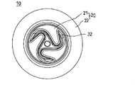
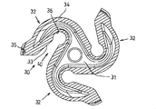
- FIG. 2 is a cross-sectional view taken along the line BB in FIG. 1 and is an explanatory cross-sectional view illustrating a leg portion of an embodiment of the hole plug according to the present invention. It is a bottom view which shows one Embodiment of the hole plug which concerns on this invention.
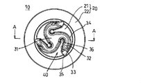
- FIG. 5 is a cross-sectional view taken along line AA in FIG. 4.
- the hole plug 10 is formed of a head 20 and leg portions 30 provided so as to protrude from the approximate center of the head 20.
- a material such as thermoplastic elastomer (TPE) or polyethylene (PE) is used for the hole plug 10.
- TPE thermoplastic elastomer
- PE polyethylene
- the head 20 is formed of a flat surface 21 formed in a substantially circular shape in plan view, and a flange 22 formed around the edge of the flat surface 21 and formed in a substantially annular shape.
- the heel 22 is inclined in the direction of the leg 30 rather than the flat surface 21 when viewed from the front.
- the shape of the flange 22 is not limited to a substantially annular shape, and may be made to circulate along the edge of the flat surface 21 and be a polygonal shape together with the flat surface 21.
- the leg 30 is provided so as to protrude in the axial direction from the flat surface 21 of the head 20 (see FIG. 5).
- the leg portion 30 is formed of a central portion 31 that is coaxial with the flat surface 21, and three wing portions 32 that extend from the central portion 31 while being curved in the radial direction. Therefore, the shape of the leg 30 in plan view is spiral.
- the cross-sectional shape in plan view of the central portion 31 is formed in a substantially triangular shape in which the base portions of adjacent wing portions 32 are connected to each other.
- the wing portion 32 is curved and extends counterclockwise from the central portion 31 and is extended so that the tip is along the edge of the flat surface 21 of the head 20 (see FIGS. 2 and 3).
- the spiral direction of the entire three wings 32 is not limited to the counterclockwise direction, and may be clockwise.
- the wing part 32 has an inner peripheral wall part 33 on the side facing the center part 31, an outer peripheral wall part 34 opposite to the inner peripheral wall part 33, and a tip where the inner peripheral wall part 33 and the outer peripheral wall part 34 are connected.
- the wall portion 35 is formed.
- the inner peripheral wall portion 33 extends from the central portion 31 via the hinge portion 36.
- the wing parts 32 are provided at substantially equal intervals in the circumferential direction of the center part 31.
- the wing part 32 is formed so as to move away from the center part 31 as the inner peripheral wall part 33 moves toward the tip wall part 35.
- a gap serving as a bending margin 40 is formed between the inner peripheral wall portion 33 and the central portion 31.
- the bending margin 40 allows the wing portion 32 to bend toward the center portion 31.
- the bending margin 40 is formed so as to gradually spread with the hinge portion 36 as a base point. Therefore, since the bending margin 40 can be widened in the vicinity of the tip wall portion 35, the wing portion 32 can be greatly bent.
- the center part 31 and the wing part 32 are both formed hollow. That is, a closed path is formed by the entire leg portion 30 including the three sets of the inner peripheral wall portion 33, the outer peripheral wall portion 34, the tip wall portion 35, and the hinge portion 36, and the central portion 31.
- the inner peripheral wall portion 33 is a side wall on the side facing the center portion 31 among the side walls forming the wing portion 32. One end of the inner peripheral wall portion 33 is connected to one end of the outer peripheral wall portion 34. Thereby, the tip wall part 35 is formed. The other end of the inner peripheral wall portion 33 is connected to the hinge portion 36.
- the hinge portion 36 is formed to be bent in a substantially U shape in plan view. One end of the hinge portion 36 is connected to the other end of the outer peripheral wall portion 34 of the other wing portion 32 adjacent to the counterclockwise side. The other end of the hinge portion 36 is connected to the other end of the inner peripheral wall portion 33. The hinge part 36 becomes a fulcrum when the wing part 32 is bent.
- the hinge part 36 is formed thinner than any part of the inner peripheral wall part 33, the outer peripheral wall part 34, and the tip wall part 35. Since the hinge part 36 is thin, the easiness of bending of the wing
- PE polyethylene
- the outer peripheral wall portion 34 on the opposite side of the inner peripheral wall portion 33 is a side wall on the opposite side of the central portion 31 across the inner peripheral wall portion 33 among the side walls forming the wing portion 32.
- the outer peripheral wall portion 34 is formed in an arc shape, and one end thereof is connected to one end of the inner peripheral wall portion 33. Thereby, the tip wall part 35 is formed.
- the other end of the outer peripheral wall portion 34 is connected to a hinge portion 36 of another wing portion 32 adjacent to the clockwise side.
- the outer peripheral wall portion 34 is gradually formed thinner toward the tip wall portion 35. Therefore, the ease of bending of the wing portion 32 can be ensured.
- the tip wall portion 35 is formed to be thicker than the outer peripheral wall portion 34 and the inner peripheral wall portion 33. Therefore, it is possible to secure the bending holding force while securing the ease of bending of the wing portion 32.
- a claw portion 37 is formed on the tip wall portion 35.
- the claw portion 37 is formed by providing a notch in a part near the head 20 at the edge of the tip wall portion 35.
- a groove is formed in the tip wall portion 35 by the notch, and a claw portion 37 is formed by the end of the groove.
- the notch is formed at substantially the same height as the edge of the flange 22 in the axial direction.
- the tip wall portion 35 is formed with an inclined portion 38 formed by constricting from the claw portion 37 toward the tip of the leg portion 30.
- the hole plug 10 according to the present embodiment is configured as described above.
- the hole plug 10 is inserted from the leg portion 30 side into a work hole or a paint hole opened in a vehicle panel (not shown).
- the diameter of the tip which is the minimum diameter of the leg 30 is formed smaller than the diameter of the hole.
- the diameter where the claw part 37 which is the maximum diameter of the leg part 30 is located is formed larger than the diameter of the hole. Therefore, the leg part 30 can be inserted into the hole from the tip, and a part of the inclined part 38 formed on the tip wall part 35 of the wing part 32 constituting the leg part 30 is caught on the edge of the hole.
- the leg portion 30 is formed in a spiral shape in the radial direction from the center portion 31. Therefore, the bending margin 40 can be taken between the wing part 32 and the center part 31, and the clearance of the claw part 37 can be secured, and even hole diameters having different sizes can be allowed. Specifically, a range of about ⁇ 1 mm can be allowed.
- the pressure of the leg 30 acts in the radial direction of the leg 30 when the flat surface 21 of the head 20 is pressed.
- a repulsive force acts from the edge of the hole.
- the inner peripheral wall portion 33 of the wing portion 32 formed of a flexible material approaches the center portion 31 with the hinge portion 36 as a fulcrum. That is, the wing part 32 bends toward the center part 31.
- the diameter of the leg 30 is reduced.
- the wing part 32 and the center part 31 are formed hollow.
- the outer peripheral wall portion 34 is gradually formed thinner toward the tip wall portion 35.
- the tip wall portion 35 is formed thicker than the outer peripheral wall portion 34 and the inner peripheral wall portion 33.
- the inner peripheral wall portion 33 extends from the center portion 31 via a thin hinge portion 36.
- the wing portions 32 are provided at substantially equal intervals in the circumferential direction of the center portion 31, and are formed so as to be separated from the center portion 31 as the inner peripheral wall portion 33 moves toward the tip wall portion 35.
- the hole plug 10 pressed against the flat surface 21 is inserted deeply in the pressed direction, that is, from the opening surface toward the hole.
- the tip of the flange 22 that forms the head 20 having a diameter larger than the hole comes into contact with the opening surface.
- the reed 22 is formed of a flexible material, the reed force from the opening surface causes the reed 22 to bend and bend with an inclination angle so as to approach the horizontal.
- the head 20 is formed with the bending margin by the flange 22, plate thicknesses having different thicknesses can be allowed.
- the claw portion 37 formed on the tip wall portion 35 of the wing portion 32 engages with the edge of the hole.
- the leg portion 30 whose diameter is reduced tends to return to the original diameter due to the flexibility of the material.
- the flange 22 is pushed from the opening surface and tries to return to the original inclination angle. Therefore, a repulsive force is generated in the radial direction and the axial direction, and the hole plug 10 is reliably engaged with the edge of the hole.
- the leg portion 30 includes the central portion 31 that is coaxial with the head portion 20, and a plurality of wings that are radially extended from the central portion 31.
- the wing portion 32 is formed of a portion 32, and the wing portion 32 has an inner peripheral wall portion 33 on the side facing the central portion 31, an outer peripheral wall portion 34 on the opposite side of the inner peripheral wall portion 33, an inner peripheral wall portion 33 and an outer peripheral wall portion 34
- the tip wall portion 35 includes a claw portion 37 that engages with the edge of the hole, and an inclined portion that is narrowed from the claw portion 37 toward the tip of the leg portion 30. 38.
- either the center portion 31 or the wing portion 32 is formed hollow.
- this configuration it is possible to easily ensure the flexibility of the wing portion 32 and the escape of the claw portion 37, and it is possible to expand a range in which hole diameters having different sizes are allowed. Further, the insertion force when the hole plug 10 is inserted can be reduced.
- the outer peripheral wall portion 34 is gradually formed thinner toward the tip wall portion 35.
- the tip wall portion 35 is formed thicker than the outer peripheral wall portion 34 and the inner peripheral wall portion 33.
- the inner peripheral wall portion 33 extends from the center portion 31 via the hinge portion 36, and the hinge portion 36 is thinner than the outer peripheral wall portion 34, the inner peripheral wall portion 33, and the tip wall portion 35. Is formed. With this configuration, the ease of bending of the wing portion 32 can be further improved.
- the wing portions 32 are provided at substantially equal intervals in the circumferential direction of the center portion 31, and are formed so as to be separated from the center portion 31 as the inner peripheral wall portion 33 moves toward the tip wall portion 35. With this configuration, the bending margin 40 of the wing portion 32 can be secured more widely.
- the central portion 31 is formed in a substantially S shape or a substantially polygonal shape according to the number of the wing portions 32.
- the center portion 31 and the wing portion 32 are both formed hollow.
- one of the center part and the wing part may be hollow and the other may be solid. Even if only one of them is hollow, escape of the claw portion can be secured, and hole diameters having different sizes can be allowed.
- the insertion force into the hole can be reduced.
- both the center portion 31 and the wing portion 32 are hollow. This is because it is possible to ensure the relief of the claw portion and to expand the range that allows different hole diameters. Moreover, it is because the insertion force to a hole can further be reduced.
- the wing portion is hollow, the wing portion itself can be bent when the inner peripheral wall portion and the outer peripheral wall portion are close to each other when the wing portion is bent, so that a wider bending margin can be obtained.
- the number of the wing parts 32 is three, the plan view cross section of the center part 31 is substantially triangular.
- the number of wings is not limited to three, and may be a simple configuration of two or four or more configurations. With two configurations, the material is reduced and the cost is economical. If it is set as four or more structures, each wing
- the number of wings is preferably three. Compared to the case of two configurations, each wing portion bends in a well-balanced manner. Also, compared to the case of four or more configurations, the wing portions are hard to bend when densely packed. This is because there is no need to use.
- the cross section in plan view of the center part becomes a gentle substantially S-shape integrally with the wing parts. Further, when the number of wing parts is four or more, the cross section in plan view of the center part is a substantially quadrangular shape or a substantially polygonal shape. By increasing or decreasing the number of wings, it is possible to adjust the deflection margin and the holding force of the deflection.
Landscapes
- Engineering & Computer Science (AREA)
- General Engineering & Computer Science (AREA)
- Mechanical Engineering (AREA)
- Chemical & Material Sciences (AREA)
- Combustion & Propulsion (AREA)
- Transportation (AREA)
- Pressure Vessels And Lids Thereof (AREA)
Abstract
被取付部材に開口された穴よりも径が大きい頭部と、この頭部の略中央から突出させて設けられた脚部とを備えた、開口を塞ぐためのホールプラグであって、脚部を、頭部と同軸である中心部と、この中心部から径方向に湾曲させて延設された複数の翼部とで形成し、翼部を、中心部と対峙する側の内周壁部と、この内周壁部の反対側の外周壁部と、内周壁部と外周壁部とを連接させた先端壁部とで形成し、先端壁部を、穴の縁と係合する爪部と、この爪部から脚部の先端に向けて窄ませた傾斜部とで形成してホールプラグを構成する。
Description
本発明は、自動車のパネルなどに開口された穴を塞ぐホールプラグに関するものである。
従来から、自動車のパネルなどに開口された作業穴や塗装抜き穴は、開口される場所によってその穴径、板厚が異なる。このため、作業穴や塗装抜き穴を塞ぐホールプラグの型を各穴径に合わせて起こしていた。したがって、各穴径ごとに異なるホールプラグが存在していた。そこで、下記特許文献1に示すような閉塞栓が提案されている。
上記閉塞栓は、底部と、該底部の周囲側から立ち上げられた外周壁と、該外周壁の上縁で放射方向に延設された鍔部と、上記外周壁の外側壁面に設けられパネル穿設孔の周縁に嵌まる係合溝と、上記底部の内部側表面より上方に立ち上げられた押圧部と、上記外周壁と上記底部と上記押圧部との間に形成される管状溝とを備え、上記押圧部の上面が上記鍔部の上面よりも上方に位置するものである。
上記した閉塞栓は、押圧部を押圧することで外周壁が内側へ撓み、また、管状溝を設けたことで撓みやすくなり、一度の押圧で穴への装着作業が完了するという効果を奏する。
しかし、上記した閉塞栓においては、以下のような問題がある。
この閉塞栓は、開口された穴へ挿入する際、係合溝が撓むスペース、すなわち、撓みしろがほとんどなく、材料の弾性を利用することで係合溝を撓ませて縮径させ、穴へ圧入していた。このため、異なる穴径を許容する範囲が狭く、例えば、±0.3mm程度の範囲にとどまっていた。また、穴径の最大時と最少時とでの挿入力、抜去力の差が大きかった。
この閉塞栓は、開口された穴へ挿入する際、係合溝が撓むスペース、すなわち、撓みしろがほとんどなく、材料の弾性を利用することで係合溝を撓ませて縮径させ、穴へ圧入していた。このため、異なる穴径を許容する範囲が狭く、例えば、±0.3mm程度の範囲にとどまっていた。また、穴径の最大時と最少時とでの挿入力、抜去力の差が大きかった。
本発明は、上記の実情に鑑みて提案されたものである。すなわち、撓みしろを広くとることで異なる穴径を許容する範囲を拡大し、部品の統合化を図ることができるホールプラグを提供することを目的とする。
上記目的を達成するために、本発明は、被取付部材に開口された穴よりも径が大きい頭部と、前記頭部の略中央から突出させて設けられた脚部と、を備えた前記開口を塞ぐためのホールプラグであって、前記脚部は、前記頭部と同軸である中心部と、この中心部から径方向に湾曲させて延設された複数の翼部とから形成され、前記翼部は、前記中心部と対峙する側の内周壁部と、この内周壁部の反対側の外周壁部と、前記内周壁部と前記外周壁部とを連接させた先端壁部とから形成され、前記先端壁部は、前記穴の縁と係合する爪部と、この爪部から前記脚部の先端に向けて窄ませた傾斜部とから形成されることを特徴としている。
また、前記中心部または前記翼部のいずれか一方は、中空に形成されていることが好ましい。
この構成により、翼部の撓みやすさと、爪部の逃げを確保しやすくすることができ、大きさが異なる穴径を許容する範囲を拡大することができる。また、ホールプラグ挿入時の、挿入力を低減することができる。
この構成により、翼部の撓みやすさと、爪部の逃げを確保しやすくすることができ、大きさが異なる穴径を許容する範囲を拡大することができる。また、ホールプラグ挿入時の、挿入力を低減することができる。
また、前記外周壁部は、前記先端壁部に向かって徐々に肉薄に形成されていることが好ましい。
この構成により、翼部の撓みやすさを確実に確保することができる。
この構成により、翼部の撓みやすさを確実に確保することができる。
また、前記先端壁部は、前記外周壁部および前記内周壁部よりも肉厚に形成されていることが好ましい。
この構成により、翼部の撓みやすさを確実に確保しつつ、撓みの保持力を確保することができる。
この構成により、翼部の撓みやすさを確実に確保しつつ、撓みの保持力を確保することができる。
また、前記内周壁部は、ヒンジ部を介して前記中心部から延設され、このヒンジ部は、前記外周壁部、前記内周壁部、前記先端壁部よりも肉薄に形成されていることが好ましい。
この構成により、翼部の撓みやすさを更に向上させることができる。
この構成により、翼部の撓みやすさを更に向上させることができる。
また、前記翼部は、前記中心部の周方向に略等間隔に設けられ、前記内周壁部が前記先端壁部へ向かうにつれて前記中心部から離れるように形成されていることが好ましい。
この構成により、翼部の撓みしろをより広く確保することができる。
この構成により、翼部の撓みしろをより広く確保することができる。
また、前記中心部は、前記翼部の数に応じて略S字形状または略多角形状に形成されていることが好ましい。
この構成により、翼部の数を増減することで、翼部の撓みしろをより広く確保し、または調整することができる。
この構成により、翼部の数を増減することで、翼部の撓みしろをより広く確保し、または調整することができる。
本発明に係るホールプラグによれば、撓みしろを確保することができ、爪部の逃げを確保して、大きさが異なる穴径を許容する範囲を拡大することができる。具体的には、±1mm程度の範囲まで許容することができる。また、穴径の最大時と最少時とにおける、ホールプラグの挿入時、抜去時の、挿入力、抜去力の差を少なくすることができる。
以下に、本発明の実施形態を図面に基づいて説明する。なお、本実施形態は、本発明の実施形態の一つを例示して説明するものである。したがって、本発明は、本実施形態に限定されるものではない。
図1、図2において、本実施形態に係るホールプラグ10は、頭部20と、頭部20の略中央から突出させて設けられた脚部30とから形成されている。
ホールプラグ10には、例えば、熱可塑性エラストマー(TPE)や、ポリエチレン(PE)などの素材が用いられる。特に、TPEよりも安価なPEを用いれば経済面において好ましい。
頭部20は、平面視して、略円形状に形成された平坦面21と、この平坦面21の縁に沿って周回させ、略環状に形成された鍔22とから形成されている。鍔22は、正面視して、平坦面21よりも脚部30の方向へ傾斜している。なお、鍔22の形状は略環状に限られず、平坦面21の縁に沿って周回させ、この平坦面21と合わせて多角形状としてもよい。
脚部30は、頭部20の平坦面21から軸方向に突出させて設けられている(図5参照)。図3において、脚部30は、平坦面21と同軸である中心部31と、この中心部31から径方向に湾曲させて延設された3つの翼部32とから形成されている。したがって、脚部30を平面視した形状は、渦巻き状となっている。
中心部31の平面視断面形状は、隣り合う翼部32の基部同士が連接した略三角形状に形成されている。
翼部32は、中心部31から反時計回りに湾曲させて延びるとともに先端が頭部20の平坦面21の縁に沿うように延設されている(図2、図3参照)。なお、3つの翼部32全体の渦巻き状の向きは、反時計回りに限られず、時計回りであってもよい。
翼部32は、中心部31と対峙する側の内周壁部33と、この内周壁部33の反対側の外周壁部34と、この内周壁部33と外周壁部34とが連接された先端壁部35とから形成されている。内周壁部33は、ヒンジ部36を介して中心部31から延設されている。
翼部32は、中心部31の周方向に略等間隔に設けられている。翼部32は、内周壁部33が先端壁部35へ向かうにつれて中心部31から離れるように形成されている。
すなわち、内周壁部33と中心部31との間には撓みしろ40となる隙間が形成されている。この撓みしろ40により、翼部32は、中心部31に向かって撓むことができる。撓みしろ40は、ヒンジ部36を基点として徐々に広がるように形成されている。したがって、先端壁部35付近で撓みしろ40を広くとることができるため、翼部32を大きく撓ませることができる。
中心部31および翼部32は、いずれも中空に形成されている。すなわち、3組の内周壁部33と外周壁部34と先端壁部35とヒンジ部36とからなる脚部30全体と、中心部31とで閉路が形成されている。
内周壁部33は、翼部32を形成する側壁のうち中心部31に対峙する側の側壁である。内周壁部33の一端は、外周壁部34の一端に連接されている。これにより、先端壁部35が形成されている。内周壁部33の他端は、ヒンジ部36に連接されている。
ヒンジ部36は、平面視で略U字状に湾曲して形成されている。ヒンジ部36の一端は、反時計回り側に隣接する他の翼部32の外周壁部34の他端に連接されている。ヒンジ部36の他端は、内周壁部33の他端に連接されている。ヒンジ部36は、翼部32を撓ませる際の支点となる。
ヒンジ部36は、内周壁部33と、外周壁部34と、先端壁部35のいずれの部分よりも肉薄に形成されている。ヒンジ部36が肉薄であるため、翼部32の撓みやすさを更に向上させることができる。また、素材にポリエチレン(PE)を用いて挿入力が増大しても、ヒンジ部36を肉薄にし、併せて上記したように撓みしろ40を広くとることで、増大した挿入力を低減させることができる。
内周壁部33の反対側の外周壁部34は、翼部32を形成する側壁のうち、内周壁部33を挟んで中心部31の反対側の側壁である。外周壁部34は弧状に形成され、一端が内周壁部33の一端に連接されている。これにより先端壁部35が形成されている。外周壁部34の他端は、時計回り側に隣接する他の翼部32のヒンジ部36に連接されている。
外周壁部34は、先端壁部35に向かって徐々に肉薄に形成されている。したがって、翼部32の撓みやすさを確保することができる。
先端壁部35は、外周壁部34および内周壁部33よりも肉厚に形成されている。したがって、翼部32の撓みやすさを確保しつつ、撓みの保持力も確保することができる。
図5において、先端壁部35には、爪部37が形成されている。爪部37は、先端壁部35の縁で頭部20寄りの一部に切り欠きを設けることで形成されている。切り欠きにより、先端壁部35には溝が形成され、溝の端により爪部37が形成されている。切り欠きは、軸方向で鍔22の縁とほぼ同じ高さに形成されている。
先端壁部35には、爪部37から脚部30の先端に向けて窄ませて形成された傾斜部38が形成されている。
以上のようにして、本実施形態に係るホールプラグ10は構成されている。
次に、本実施形態に係るホールプラグ10の作用について説明する。
図3、図4、図5において、図示しない自動車のパネルなどに開口された作業穴や塗装抜き穴に、ホールプラグ10を脚部30側から挿入する。脚部30の最少径である先端の径は、穴の径よりも小さく形成されている。脚部30の最大径である爪部37が位置する径は、穴の径よりも大きく形成されている。したがって、脚部30を先端から穴に挿入することができ、脚部30を構成する翼部32の先端壁部35に形成された傾斜部38の一部が、穴の縁に引っ掛かる。
ここで、穴径や板厚は、開口される場所によって異なるが、本実施形態では、脚部30は、中心部31から径方向に渦巻き状に形成されている。したがって、翼部32によって中心部31との間に撓みしろ40をとることができ、爪部37の逃げを確保して大きさが異なる穴径でも許容することができる。具体的には、±1mm程度の範囲まで許容することができる。
脚部30は、傾斜部38の一部が穴の縁に引っ掛かっているため、頭部20の平坦面21を押圧すると、圧力が脚部30の径方向に働く。圧力が脚部30の径方向に働くと、穴の縁からは反発力が働く。反発力が働くと、可撓性の素材で形成された翼部32は、ヒンジ部36を支点に内周壁部33が中心部31に近づく。すなわち、翼部32は中心部31に向かって撓む。翼部32が撓むと、脚部30の径が縮む。
特に、本実施形態では、翼部32および中心部31は中空に形成されている。更に、外周壁部34は、先端壁部35に向かって徐々に肉薄に形成されている。また、先端壁部35は、外周壁部34および内周壁部33よりも肉厚に形成されている。また、内周壁部33は、肉薄のヒンジ部36を介して中心部31から延設されている。また、翼部32は、中心部31の周方向で略等間隔に設けられ、内周壁部33が先端壁部35へ向かうにつれて中心部31から離れるように形成されている。
このように構成することにより、撓みの保持力を確保しつつ、翼部32の撓みやすさが向上し、また、撓みしろ40を広くとることができる。したがって、脚部30の径を、容易に、かつ、大きく伸縮することができるため、異なる穴径を許容する範囲を拡大することができる。
脚部30の径が縮むと、平坦面21を押圧されたホールプラグ10は、押圧された方向へ、すなわち、開口面から穴の方向へ深く挿入される。脚部30の径が縮みながらホールプラグ10が穴に挿入されると、穴よりも径が大きい頭部20を形成する鍔22の先端が開口面に接触する。ここで、鍔22は可撓性の素材から形成されているため、開口面からの反発力によって鍔22は水平に近づくように傾斜角が広がって撓む。
このように、頭部20には鍔22によって撓みしろが形成されているため、厚さが異なる板厚を許容することができる。
鍔22を撓ませながらホールプラグ10が穴に挿入されると、翼部32の先端壁部35に形成された爪部37が穴の縁に係合する。爪部37が穴の縁に係合すると、径が縮んだ脚部30は、素材の可撓性により元の径に戻ろうとする。同様に、鍔22も、開口面から押されて元の傾斜角に戻ろうとする。したがって、径方向と軸方向とに反発力が生じ、ホールプラグ10は確実に穴の縁と係合する。
上記したように、本実施形態に係るホールプラグ10において、脚部30は、頭部20と同軸である中心部31と、この中心部31から径方向に湾曲させて延設された複数の翼部32とから形成され、翼部32は、中心部31と対峙する側の内周壁部33と、この内周壁部33の反対側の外周壁部34と、内周壁部33と外周壁部34とを連接させた先端壁部35とから形成され、先端壁部35は、穴の縁と係合する爪部37と、この爪部37から脚部30の先端に向けて窄ませた傾斜部38とから形成される。
この構成により、翼部32によって撓みしろ40をとることができ、爪部37の逃げを確保して、大きさが異なる穴径を許容する範囲を拡大することができる。具体的には、±1mm程度の差まで許容することができる。また、穴径の最大時と最少時とにおける、ホールプラグ10の挿入時、抜去時の、挿入力、抜去力の差を少なくすることができる。
この構成により、翼部32によって撓みしろ40をとることができ、爪部37の逃げを確保して、大きさが異なる穴径を許容する範囲を拡大することができる。具体的には、±1mm程度の差まで許容することができる。また、穴径の最大時と最少時とにおける、ホールプラグ10の挿入時、抜去時の、挿入力、抜去力の差を少なくすることができる。
特に、本実施形態において、中心部31または翼部32のいずれか一方は、中空に形成されている。この構成により、翼部32の撓みやすさと、爪部37の逃げを確保しやすくすることができ、大きさが異なる穴径を許容する範囲を拡大することができる。また、ホールプラグ10挿入時の、挿入力を低減することができる。
特に、本実施形態において、外周壁部34は、先端壁部35に向かって徐々に肉薄に形成されている。この構成により、翼部32の撓みやすさを確保することができる。
特に、本実施形態において、先端壁部35は、外周壁部34および内周壁部33よりも肉厚に形成されている。この構成により、翼部32の撓みやすさを確実に確保しつつ、撓みの保持力も確保することができる。
特に、本実施形態において、内周壁部33は、ヒンジ部36を介して中心部31から延設され、このヒンジ部36は、外周壁部34、内周壁部33、先端壁部35よりも肉薄に形成されている。この構成により、翼部32の撓みやすさを更に向上させることができる。
特に、本実施形態において、翼部32は、中心部31の周方向に略等間隔に設けられ、内周壁部33が先端壁部35へ向かうにつれて中心部31から離れるように形成されている。この構成により、翼部32の撓みしろ40をより広く確保することができる。
特に、本実施形態において、中心部31は、翼部32の数に応じて略S字形状または略多角形状に形成されている。この構成により、翼部32の数を増減することで、翼部32の撓みしろ40をより広く確保し、または調整することができる。
上記した実施形態によれば、中心部31および翼部32を、いずれも中空に形成した。しかし、中心部および翼部は、いずれか一方を中空とし、他方を中実としてもよい。中空とするのがいずれか一方のみであっても、爪部の逃げを確保することができ、大きさの異なる穴径を許容することができる。また、穴への挿入力を低減させることができる。ただし、上記した実施形態のように、中心部31および翼部32は、いずれも中空であることが好ましい。確実に爪部の逃げを確保することができ、異なる穴径を許容する範囲を拡大することができるためである。また、穴への挿入力を更に低減させることができるためである。
なお、翼部が中空であれば、撓ませる際に内周壁部と外周壁部とが近接することで翼部自身も撓ませることができるため、更に撓みしろを広くとることができる。
上記した実施形態によれば、翼部32の数を3つとしたため、中心部31の平面視断面は略三角形状である。しかし、翼部の数は3つに限られず、2つとした簡便な構成でもよく、または4つ以上の構成としてもよい。2つ構成とすれば、材料が減り、経済面で安価となる。4つ以上の構成とすれば、各翼部がバランスよく撓み、確実に穴と係合される。ただし、上記した実施形態のように、翼部の数は3つとすることが好ましい。2つ構成とした場合に比べて、各翼部がバランスよく撓み、また、4つ以上の構成とした場合と比べて、翼部が密集した場合に撓みが固くなることも、必要以上に材料を使うこともないためである。
なお、翼部の数が2つであれば、中心部の平面視断面は、翼部と一体となって緩やかな略S字形状となる。また、翼部の数が4つ以上であれば、中心部の平面視断面は、略四角形状またはそれ以上の略多角形状となる。翼部の数を増減することで、撓みしろや、撓みの保持力を調整することができる。
以上、本発明の実施形態を詳述したが、本発明は上記実施形態に限定されるものではない。そして本発明は、特許請求の範囲に記載された事項を逸脱することがなければ、種々の設計変更を行うことが可能である。
2011年5月18日に出願された日本特許出願第2011-111434号の明細書、特許請求の範囲、図面及び要約書の全内容をここに引用し、本発明の明細書の開示として、取り入れるものである。
2011年5月18日に出願された日本特許出願第2011-111434号の明細書、特許請求の範囲、図面及び要約書の全内容をここに引用し、本発明の明細書の開示として、取り入れるものである。
Claims (7)
- 被取付部材に開口された穴よりも径が大きい頭部と、前記頭部の略中央から突出させて設けられた脚部と、を備えた前記開口を塞ぐためのホールプラグであって、
前記脚部は、前記頭部と同軸である中心部と、この中心部から径方向に湾曲させて延設された複数の翼部とから形成され、
前記翼部は、前記中心部と対峙する側の内周壁部と、この内周壁部の反対側の外周壁部と、前記内周壁部と前記外周壁部とを連接させた先端壁部とから形成され、
前記先端壁部は、前記穴の縁と係合する爪部と、この爪部から前記脚部の先端に向けて窄ませた傾斜部とから形成される、
ことを特徴とするホールプラグ。 - 前記中心部または前記翼部のいずれか一方は、中空に形成されていること、
を特徴とする請求項1に記載のホールプラグ - 前記外周壁部は、前記先端壁部に向かって徐々に肉薄に形成されていること、
を特徴とする請求項1または請求項2に記載のホールプラグ。 - 前記先端壁部は、前記外周壁部および前記内周壁部よりも肉厚に形成されていること、
を特徴とする請求項1ないし請求項3のいずれか1項に記載のホールプラグ。 - 前記内周壁部は、ヒンジ部を介して前記中心部から延設され、このヒンジ部は、前記外周壁部、前記内周壁部、前記先端壁部よりも肉薄に形成されていること、
を特徴とする請求項1ないし請求項4のいずれか1項に記載のホールプラグ。 - 前記翼部は、前記中心部の周方向に略等間隔に設けられ、前記内周壁部が前記先端壁部へ向かうにつれて前記中心部から離れるように形成されていること、
を特徴とする請求項1ないし請求項5のいずれか1項に記載のホールプラグ。 - 前記中心部は、前記翼部の数に応じて略S字形状または略多角形状に形成されていること、
を特徴とする請求項1ないし請求項6のいずれか1項に記載のホールプラグ。
Applications Claiming Priority (2)
| Application Number | Priority Date | Filing Date | Title |
|---|---|---|---|
| JP2011-111434 | 2011-05-18 | ||
| JP2011111434A JP2012241777A (ja) | 2011-05-18 | 2011-05-18 | ホールプラグ |
Publications (1)
| Publication Number | Publication Date |
|---|---|
| WO2012157614A1 true WO2012157614A1 (ja) | 2012-11-22 |
Family
ID=47176931
Family Applications (1)
| Application Number | Title | Priority Date | Filing Date |
|---|---|---|---|
| PCT/JP2012/062324 Ceased WO2012157614A1 (ja) | 2011-05-18 | 2012-05-14 | ホールプラグ |
Country Status (2)
| Country | Link |
|---|---|
| JP (1) | JP2012241777A (ja) |
| WO (1) | WO2012157614A1 (ja) |
Cited By (3)
| Publication number | Priority date | Publication date | Assignee | Title |
|---|---|---|---|---|
| WO2018048764A1 (en) * | 2016-09-09 | 2018-03-15 | Illinois Tool Works Inc. | Expandable hole plug |
| CN110525523A (zh) * | 2018-05-25 | 2019-12-03 | 伊利诺斯工具制品有限公司 | 轻量孔塞 |
| CN112046414A (zh) * | 2019-06-05 | 2020-12-08 | 伊利诺斯工具制品有限公司 | 密封插塞 |
Citations (5)
| Publication number | Priority date | Publication date | Assignee | Title |
|---|---|---|---|---|
| JPS5574816U (ja) * | 1978-11-20 | 1980-05-23 | ||
| JPS6071762U (ja) * | 1983-10-24 | 1985-05-21 | トヨタ自動車株式会社 | グロメツト |
| JPH0771601A (ja) * | 1992-12-14 | 1995-03-17 | Trw United Carr Gmbh & Co Kg | 閉鎖蓋 |
| JP2009528496A (ja) * | 2006-03-02 | 2009-08-06 | アイ.ティー.ダブリュ.ドゥ フランス | パネルの穴に押し込むスナップ式の係合部を備える締結具 |
| JP2009281581A (ja) * | 2008-04-25 | 2009-12-03 | Piolax Inc | クリップ |
-
2011
- 2011-05-18 JP JP2011111434A patent/JP2012241777A/ja active Pending
-
2012
- 2012-05-14 WO PCT/JP2012/062324 patent/WO2012157614A1/ja not_active Ceased
Patent Citations (5)
| Publication number | Priority date | Publication date | Assignee | Title |
|---|---|---|---|---|
| JPS5574816U (ja) * | 1978-11-20 | 1980-05-23 | ||
| JPS6071762U (ja) * | 1983-10-24 | 1985-05-21 | トヨタ自動車株式会社 | グロメツト |
| JPH0771601A (ja) * | 1992-12-14 | 1995-03-17 | Trw United Carr Gmbh & Co Kg | 閉鎖蓋 |
| JP2009528496A (ja) * | 2006-03-02 | 2009-08-06 | アイ.ティー.ダブリュ.ドゥ フランス | パネルの穴に押し込むスナップ式の係合部を備える締結具 |
| JP2009281581A (ja) * | 2008-04-25 | 2009-12-03 | Piolax Inc | クリップ |
Cited By (6)
| Publication number | Priority date | Publication date | Assignee | Title |
|---|---|---|---|---|
| WO2018048764A1 (en) * | 2016-09-09 | 2018-03-15 | Illinois Tool Works Inc. | Expandable hole plug |
| CN110525523A (zh) * | 2018-05-25 | 2019-12-03 | 伊利诺斯工具制品有限公司 | 轻量孔塞 |
| CN112046414A (zh) * | 2019-06-05 | 2020-12-08 | 伊利诺斯工具制品有限公司 | 密封插塞 |
| EP3747743A1 (en) * | 2019-06-05 | 2020-12-09 | Illinois Tool Works Inc. | Sealing plugs |
| US11578800B2 (en) | 2019-06-05 | 2023-02-14 | Illinois Tool Works Inc. | Sealing plugs |
| CN112046414B (zh) * | 2019-06-05 | 2024-07-02 | 伊利诺斯工具制品有限公司 | 密封插塞 |
Also Published As
| Publication number | Publication date |
|---|---|
| JP2012241777A (ja) | 2012-12-10 |
Similar Documents
| Publication | Publication Date | Title |
|---|---|---|
| USD900445S1 (en) | Shoe | |
| JP5921353B2 (ja) | ホールプラグ | |
| JP6122336B2 (ja) | ホールプラグ | |
| KR101481360B1 (ko) | 2피스 클립 | |
| CN102405354A (zh) | 具有带肋凸缘的紧固件 | |
| JP2004162808A (ja) | ホールプラグ | |
| EP3067574A1 (en) | A clip and fastening structure | |
| JP2014185656A (ja) | ダストカバー | |
| EP1621782A1 (en) | Female attachment and obturator including it | |
| US20150251202A1 (en) | Aerosol container fixing plate | |
| CN110890731B (zh) | 索环 | |
| WO2017064912A1 (ja) | 留め具 | |
| WO2012157614A1 (ja) | ホールプラグ | |
| JP6088231B2 (ja) | ホールプラグ | |
| CN111512076B (zh) | 孔塞 | |
| JP2019060358A (ja) | ホールプラグ | |
| JP6571367B2 (ja) | ホールプラグ | |
| JP2009293661A (ja) | プラグ | |
| JP6947628B2 (ja) | ホールプラグの取付構造 | |
| JP6298707B2 (ja) | 取付具 | |
| JP5911790B2 (ja) | ホールプラグ | |
| JP4712672B2 (ja) | クリップ | |
| JP6148854B2 (ja) | カップ容器 | |
| JP5677511B2 (ja) | 電柱キャップ | |
| JP2013217448A (ja) | ホールプラグ |
Legal Events
| Date | Code | Title | Description |
|---|---|---|---|
| 121 | Ep: the epo has been informed by wipo that ep was designated in this application |
Ref document number: 12786170 Country of ref document: EP Kind code of ref document: A1 |
|
| NENP | Non-entry into the national phase |
Ref country code: DE |
|
| 122 | Ep: pct application non-entry in european phase |
Ref document number: 12786170 Country of ref document: EP Kind code of ref document: A1 |