WO2012157437A1 - フロントアンダーランプロテクタ - Google Patents
フロントアンダーランプロテクタ Download PDFInfo
- Publication number
- WO2012157437A1 WO2012157437A1 PCT/JP2012/061368 JP2012061368W WO2012157437A1 WO 2012157437 A1 WO2012157437 A1 WO 2012157437A1 JP 2012061368 W JP2012061368 W JP 2012061368W WO 2012157437 A1 WO2012157437 A1 WO 2012157437A1
- Authority
- WO
- WIPO (PCT)
- Prior art keywords
- vehicle
- fup
- bar
- fup bar
- width direction
- Prior art date
- Legal status (The legal status is an assumption and is not a legal conclusion. Google has not performed a legal analysis and makes no representation as to the accuracy of the status listed.)
- Ceased
Links
Images

Classifications
-
- B—PERFORMING OPERATIONS; TRANSPORTING
- B60—VEHICLES IN GENERAL
- B60R—VEHICLES, VEHICLE FITTINGS, OR VEHICLE PARTS, NOT OTHERWISE PROVIDED FOR
- B60R19/00—Wheel guards; Radiator guards, e.g. grilles; Obstruction removers; Fittings damping bouncing force in collisions
- B60R19/56—Fittings damping bouncing force in truck collisions, e.g. bumpers; Arrangements on high-riding vehicles, e.g. lorries, for preventing vehicles or objects from running thereunder
Definitions
- the present invention relates to a front underrun protector for preventing a vehicle from getting into the vehicle.
- the front underrun protector prevents the passenger car from entering under the truck when the truck and passenger car collide head-on.
- a strong beam (FUP bar) is provided under the frame at the front of the truck. It is a thing. Such FUP is disclosed in Patent Document 1, for example.
- the FUP intrusion prevention device
- the FUP is generally composed mainly of an FUP bar corresponding to a bumper and a bracket for connecting the FUP bar to a track frame.
- the FUP bar is connected to a pair of brackets installed in the frame width, whereas the FUP bar has a length extending over the entire length of the vehicle width. That is, the FUP bar protrudes in the form of a cantilever beam toward the left and right vehicle ends with each bracket as a support point.
- the FUP bar bends toward the rear of the vehicle with a relatively low load using the connecting portion with the bracket as a fulcrum. There is a risk of it.
- an object of the present invention is to prevent the opponent vehicle from getting into the vehicle when an offset frontal collision with another vehicle is performed, and to absorb the energy at the time of the collision so as to appropriately reduce the speed of the opponent vehicle.
- the purpose is to keep the (intrusion amount of the instrument panel and floor into the cabin) low.
- the present invention is arranged below a frame of a vehicle, and is provided with an FUP bar extending in the vehicle width direction and attached to the frame at an interval in the vehicle width direction.
- a pair of brackets extending in parallel to each other, an energy absorber that is interposed between the FUP bar and the bracket so as to extend in parallel with the vehicle front-rear direction, and absorbs energy at the time of collision by compressing and deforming, and one end portion
- the FUP bar is connected to a connecting portion with the energy absorber, the intermediate portion is bent outward in the vehicle width direction, and the other end is connected to the longitudinal end of the FUP bar.
- the energy absorber is formed in a cylindrical shape, and the connecting member is inserted into the energy absorber, and the vehicle back-and-forth direction in the vehicle rearward direction starts from a connecting portion with the energy absorber in the FUP bar.
- a second linear portion that extends obliquely outward in the vehicle width direction and is connected to the longitudinal end portion of the FUP bar.
- a part may be provided.
- the opponent vehicle in the event of an offset frontal collision with another vehicle, the opponent vehicle is prevented from getting in, and the energy at the time of the collision is absorbed to appropriately reduce the speed of the opponent vehicle. There is an excellent effect that it can be suppressed.
- FIG. 1 It is a perspective view of the front underrun protector concerning one embodiment of the present invention. It is a typical top view of the front underrun protector concerning one embodiment of the present invention. It is a typical top view of the front underrun protector which shows the deformation
- a front underrun protector (hereinafter referred to as FUP) 10 includes an FUP bar 11, a pair of brackets 12, and an energy absorber that absorbs energy at the time of collision (Hereinafter referred to as EA body) 13 and a connecting member (reinforcing pipe) 14 corresponding to a frontal collision with a low overlap rate.
- FUP front underrun protector
- the arrow Ft in FIG.1 and FIG.2 represents the vehicle front direction.
- symbol 1 has shown the flame
- the frame 1 is mainly composed of a pair of side members 2 provided at intervals in the vehicle width direction and extending in the vehicle front-rear direction, and a cross member 3 provided between the pair of side members 2. Yes.
- the FUP bar 11 is disposed below the front part of the frame 1 and extends in the vehicle width direction.
- the FUP bar 11 is made of a channel material. That is, the FUP bar 11 is formed in a substantially U-shaped section (open sectional shape) that opens in the vehicle rearward direction.
- the FUP bar 11 is formed at the center portion in the longitudinal direction, and is formed continuously with the center portion 15 extending in parallel with the vehicle width direction, and with an angle in the vehicle rear direction with respect to the vehicle width direction.
- the outer portion 16 extends.
- the pair of brackets 12 are attached to the front portion of the frame 1 with an interval in the vehicle width direction and extend downward from the frame 1.
- the bracket 12 includes a first bracket portion 17 that extends downward from the frame 1 and a second bracket portion 18 that is formed continuously with the lower end of the first bracket portion 17 and to which the EA body 13 is coupled. That is, the bracket 12 has a role of holding the EA body 13 by the front portion of the bracket 12.
- the pair of brackets 12 (first bracket portion 17) are connected to each other via a bar 19 extending in parallel with the vehicle width direction.
- the bracket 12 restricts the movement of the reinforcement pipe 14 in the vehicle width direction while allowing the reinforcement pipe 14 to move in the vehicle rearward direction when a load is applied to the longitudinal end of the FUP bar 11.
- a restriction unit 20 is provided. That is, the restricting portion 20 serves to enable the reinforcing pipe 14 to retreat when a load is applied to the longitudinal end portion of the FUP bar 11, and from the second straight portion 26 (described later) of the reinforcing pipe 14 in the vehicle width direction. It has a role of receiving the load applied to the inside.
- the restricting portion 20 is provided in the second bracket portion 18 of the bracket 12 and is provided in the hole 21 (see FIG. 2) communicating with the rear opening of the EA body 13 and the second bracket portion 18 of the bracket 12. It comprises a groove 22 that communicates with the rear part and opens outward in the vehicle width direction.
- the EA body 13 is interposed between the FUP bar 11 and the bracket 12 so as to extend in parallel with the vehicle front-rear direction, and absorbs energy at the time of collision by being compressed and deformed. That is, the FUP 10 is configured such that the EA body 13 is sandwiched between the FUP bar 11 and the bracket 12.
- the EA body 13 consists of a cylindrical pipe. That is, the EA body 13 is formed in a cylindrical shape.
- the EA body 13 is connected to the FUP bar 11 and the bracket 12 by means of bolts or the like (not shown) by flanges 23 formed at both ends.
- One end of the connecting member (reinforcing pipe) 14 is connected to the connecting portion (central portion 15) of the FUP bar 11 with the EA body 13, the middle portion is bent outward in the vehicle width direction, and the other end is FUP.
- the longitudinal end of the FUP bar 11 is connected to the longitudinal end (outer part 16) of the bar 11 and receives a load
- the longitudinal end of the FUP bar 11 is connected to the EA body 13 in the FUP bar 11.
- the connecting portion of the FUP bar 11 with the EA body 13 is pulled in the vehicle rearward direction.
- the reinforcing pipe 14 extends straight in the vehicle rearward direction starting from the connection portion of the FUP bar 11 with the EA body 13, and extends from the rear of the hole 21 of the bracket 12 to the longitudinal end portion of the FUP bar 11 in the oblique vehicle forward direction. It bends towards and is connected to the longitudinal end of the FUP bar 11.
- the reinforcing pipe 14 is a cylindrical pipe having an outer diameter smaller than that of the cylindrical pipe constituting the EA body 13.
- the reinforcing pipe 14 is connected to the FUP bar 11 using bolts or the like (not shown) by flanges (not shown) formed at both ends.
- the reinforcing pipe 14 is inserted into the EA body 13, and a first straight portion 24 (see FIG.
- a slight gap is provided between the outer peripheral surface of the reinforcing pipe 14 (first straight portion 24) and the inner peripheral surface of the EA body 13. This is because if the gap is too large, the EA body 13 may be bent and deformed when an impact is applied to the FUP bar 11 due to a frontal collision with another vehicle. For this reason, the above-mentioned gap is set to an appropriate value in consideration of the buckling deformation of the EA body 13.
- the aforementioned gap is, for example, about 5 to 6 mm.
- the FUP bar 11 does not bend in the vehicle rearward direction using the connecting portion with the bracket 12 as a fulcrum even during a frontal collision with a low overlap rate (offset frontal collision). Furthermore, it becomes possible to absorb the energy at the time of a collision.
- the FUP bar 11 in order to cope with a frontal collision with a low overlap rate, is not a general cantilever type, but the reinforcing pipe 14 as described above.
- the FUP bar 11 is reinforced.
- the first straight portion 24 from the inner side in the vehicle width direction of the reinforcing pipe 14 is formed in a linear shape extending in the vehicle front-rear direction.
- the second straight portion 26 on the outer side in the vehicle width direction of the reinforcing pipe 14 is such that the longitudinal end portion of the FUP bar 11 is FUP when a load is applied to the longitudinal end portion of the FUP bar 11 due to a collision with another vehicle.
- the bar 11 has a function of pulling the connecting portion of the FUP bar 11 with the EA body 13 in the vehicle rearward direction while restricting the rotation by stretching the connecting portion with the EA body 13 in the bar 11 so as not to bend in the vehicle rearward direction. Fulfill.
- the bracket 12 (the restricting portion 20) has the following roles (1) to (3).
- the FUP bar 11 moves backward while absorbing energy even when receiving a load F at the longitudinal end of the FUP bar 11.
- the reinforcing pipe 14 also moves backward together with the FUP bar 11 while maintaining its shape. That is, when the load F is received at the longitudinal end of the FUP bar 11, the EA body 13 is crushed between the FUP bar 11 and the bracket 12, and the FUP bar 11 and the reinforcing pipe 14 are retracted.
- the FUP 10 in the event of an offset frontal collision with another vehicle, the partner vehicle is prevented from getting in, and the energy at the time of the collision is absorbed to appropriately reduce the speed of the partner vehicle. It is possible to keep the amount of vehicle intrusion low.
- the FUP bar 11 is not limited to an open cross-sectional shape (in the illustrated example, a substantially U shape opening in the vehicle rear direction), and may be formed in a closed cross-sectional shape.
- the EA body 13 and the connecting member (reinforcing pipe) 14 are not limited to cylindrical pipes, and may be polygonal cylindrical pipes.
- the EA body 13 may be provided with a hole, a slit or the like so that the EA body 13 can be easily compressed and deformed.
- connection between the FUP bar 11 and the reinforcing pipe 14 is not limited to the connection by bolts or the like, and is connected via a pin extending in the vehicle vertical direction at the overlapping portion of the FUP bar 11 and the reinforcing pipe 14. Also good. This is because when only one side in the vehicle width direction of the FUP bar 11 is deformed, such as during an offset frontal collision, the distortion is not absorbed by the bending of the FUP bar 11 but between the FUP bar 11 and the reinforcing pipe 14. This is because the connecting portion allows the FUP bar 11 to rotate and absorb.
Landscapes
- Engineering & Computer Science (AREA)
- Mechanical Engineering (AREA)
- Body Structure For Vehicles (AREA)
Abstract
他車とオフセット正面衝突した際に、相手車両の潜り込みを防止し、且つ衝突時のエネルギーを吸収して相手車両の速度を適切に減速せしめ、相手車両の潜り込み量を低く抑える。 FUP10は、フレーム1の下方に配設されたFUPバー11と、フレーム1に車幅方向に間隔を隔てて取り付けられた一対のブラケット12と、FUPバー11とブラケット12との間に車両前後方向と平行に延びるように介設され、圧縮変形することで衝突時のエネルギーを吸収するエネルギー吸収体13と、FUPバー11に取り付けられ、FUPバー11の長手方向端部に荷重を受けた際に、FUPバー11の長手方向端部がFUPバー11におけるエネルギー吸収体13との連結部を支点として車両後方向に回動しないように規制すると共に、FUPバー11におけるエネルギー吸収体13との連結部を車両後方向へ引っ張る連結部材14とを備える。
Description
本発明は、車両の潜り込みを防止するためのフロントアンダーランプロテクタに関する。
フロントアンダーランプロテクタ(FUP)とは、トラックと乗用車とが正面衝突した場合に乗用車がトラックの下に潜り込むことを防止するもので、トラック前部のフレーム下に強固なビーム(FUPバー)を設けたものである。このようなFUPは、例えば、特許文献1に開示されている。
FUP(潜り込み防止装置)は、一般的には、バンパーに相当するFUPバーと、FUPバーをトラックのフレームに連結するブラケットとから主に構成されている。FUPバーは、車幅の全長にわたる長さがあるのに対して、フレーム幅に設置された一対のブラケットに連結されている。つまり、FUPバーは、各ブラケットを支持点として、左右の車端部に向けて片持ち梁の形で突き出している。
このような構成のFUPでは、乗用車とトラックとが低いオーバーラップ率で正面衝突(オフセット正面衝突)した場合、FUPバーはブラケットとの連結部を支点として比較的低い荷重で車両後方向へ曲がってしまう虞がある。
さらに上述のような構成である一般的なFUPにおいて、さらに安全性を高めるためにトラック側でも衝突時のエネルギーを吸収する構造とした場合、エネルギー吸収体(EA体)が潰れることに伴い、FUPバーがブラケットとの連結部を支点として車両後方向へ曲がってしまう可能性が高まってしまう。
そこで、本発明の目的は、他車とオフセット正面衝突した際に、相手車両の潜り込みを防止し、且つ衝突時のエネルギーを吸収して相手車両の速度を適切に減速せしめ、相手車両の潜り込み量(インパネや床面のキャビン内への進入量)を低く抑えることにある。
上述の目的を達成するために、本発明は、車両のフレームの下方に配設され、車幅方向に延びるFUPバーと、前記フレームに車幅方向に間隔を隔てて取り付けられ、前記フレームから下方に延びる一対のブラケットと、前記FUPバーと前記ブラケットとの間に車両前後方向と平行に延びるように介設され、圧縮変形することで衝突時のエネルギーを吸収するエネルギー吸収体と、一端部が前記FUPバーにおける前記エネルギー吸収体との連結部に連結され且つ中間部が車幅方向外側へ向かって曲げられ且つ他端部が前記FUPバーの長手方向端部に連結され、前記FUPバーの長手方向端部に荷重を受けた際に、前記FUPバーの長手方向端部が前記FUPバーにおける前記エネルギー吸収体との連結部を支点として車両後方向に回動しないように規制すると共に、前記FUPバーにおける前記エネルギー吸収体との連結部を車両後方向へ引っ張る連結部材とを備えたものである。
前記エネルギー吸収体は、筒状に形成されており、前記連結部材は、前記エネルギー吸収体に挿入され、前記FUPバーにおける前記エネルギー吸収体との連結部を起点に車両後方向へ車両前後方向と平行に延びる第一直線部と、前記第一直線部に連続して形成され、車幅方向外側へ向かって曲がる湾曲部と、前記湾曲部に連続して形成され、車両前方向へ車両前後方向に対して車幅方向外側に傾斜して延び且つ前記FUPバーの長手方向端部に連結される第二直線部とを有するものであっても良い。
前記ブラケットに、前記FUPバーの長手方向端部に荷重を受けた際に、前記連結部材の車両後方向への移動を許容しつつ、前記連結部材の車幅方向内側への移動を規制する規制部が設けられていても良い。
本発明によれば、他車とオフセット正面衝突した際に、相手車両の潜り込みを防止し、且つ衝突時のエネルギーを吸収して相手車両の速度を適切に減速せしめ、相手車両の潜り込み量を低く抑えることができるという優れた効果を奏する。
以下、本発明の好適な実施形態を添付図面に基づいて詳述する。
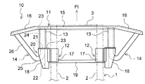
図1及び図2に示すように、本実施形態に係るフロントアンダーランプロテクタ(以下、FUPという)10は、FUPバー11と、一対のブラケット12と、衝突時のエネルギーを吸収するエネルギー吸収体(以下、EA体という)13と、低いオーバーラップ率での正面衝突に対応した連結部材(補強パイプ)14とから主に構成されている。
なお、図1及び図2中の矢印Ftは車両前方向を表している。また、図2において、符号1は車両(本実施形態では、トラック)のフレームを示している。フレーム1は、車幅方向に間隔を隔てて設けられ、車両前後方向に延びる一対のサイドメンバ2と、一対のサイドメンバ2間に架け渡して設けられたクロスメンバ3とから主に構成されている。
FUPバー11は、フレーム1前部の下方に配設され、車幅方向に延びるものである。FUPバー11は、チャンネル材からなる。つまり、FUPバー11は、車両後方向に開口する断面略U字状(開断面形状)に形成されている。FUPバー11は、その長手方向中央部に形成され、車幅方向と平行に延びる中央部15と、中央部15に連続して形成され、車幅方向に対して車両後方向に角度をつけて延びる外側部16とから構成されている。
一対のブラケット12は、フレーム1前部に車幅方向に間隔を隔てて取り付けられ、フレーム1から下方に延びるものである。ブラケット12は、フレーム1から下方に延びる第一ブラケット部17と、第一ブラケット部17の下端に連続して形成され、EA体13が連結される第二ブラケット部18とを有している。つまり、ブラケット12は、ブラケット12前部によってEA体13を保持する役割を持っている。一対のブラケット12(第一ブラケット部17)同士は、車幅方向と平行に延びるバー19を介して連結されている。
ブラケット12には、FUPバー11の長手方向端部に荷重を受けた際に、補強パイプ14の車両後方向への移動を許容しつつ、補強パイプ14の車幅方向内側への移動を規制する規制部20が設けられている。つまり、規制部20は、FUPバー11の長手方向端部に荷重を受けた際に、補強パイプ14が後退できるようにする役割と、補強パイプ14の後述する第二直線部26から車幅方向内側にかかる荷重を受け止める役割とを持っている。規制部20は、ブラケット12の第二ブラケット部18に設けられ、EA体13の後部開口に連通する孔21(図2参照)と、ブラケット12の第二ブラケット部18に設けられ、孔21の後部に連通し且つ車幅方向外側に開口する溝22とから構成されている。
EA体13は、FUPバー11とブラケット12との間に車両前後方向と平行に延びるように介設され、圧縮変形することで衝突時のエネルギーを吸収するものである。つまり、FUP10は、FUPバー11とブラケット12との間にEA体13が挟み込まれている構成となっている。EA体13は、円筒パイプからなる。つまり、EA体13は筒状に形成されている。EA体13は、両端部に形成されたフランジ23により、ボルト等(図示せず)を用いてFUPバー11及びブラケット12と各々連結されている。
連結部材(補強パイプ)14は、一端部がFUPバー11におけるEA体13との連結部(中央部15)に連結され且つ中間部が車幅方向外側へ向かって曲げられ且つ他端部がFUPバー11の長手方向端部(外側部16)に連結され、FUPバー11の長手方向端部に荷重を受けた際に、FUPバー11の長手方向端部がFUPバー11におけるEA体13との連結部を支点として車両後方向に回動しないように規制すると共に、FUPバー11におけるEA体13との連結部を車両後方向へ引っ張るものである。つまり、補強パイプ14は、FUPバー11におけるEA体13との連結部を起点に車両後方向へまっすぐに延び、ブラケット12の孔21後方から斜め車両前方向のFUPバー11の長手方向端部へ向かって曲がり、そして、FUPバー11の長手方向端部と連結されている。
補強パイプ14は、EA体13を構成している円筒パイプよりも外径が細い円筒パイプからなる。補強パイプ14は、両端部に形成されたフランジ(図示せず)により、ボルト等(図示せず)を用いてFUPバー11と連結されている。補強パイプ14は、EA体13に挿入され、FUPバー11におけるEA体13との連結部を起点に車両後方向へ車両前後方向と平行に延びる第一直線部24(図2参照)と、第一直線部24に連続して形成され、車幅方向外側へ向かって曲がる湾曲部25と、湾曲部25に連続して形成され、車両前方向へ車両前後方向に対して車幅方向外側に傾斜して延び且つFUPバー11の長手方向端部に連結される第二直線部26とを有している。
ところで、補強パイプ14(第一直線部24)の外周面とEA体13の内周面との間には、若干の隙間が設けられている。この隙間を大きくし過ぎると、他車との正面衝突でFUPバー11に衝撃が加わった際にEA体13が屈曲変形する虞があるためである。このため、前述の隙間は、EA体13の座屈変形を考慮して、適切な値に設定される。前述の隙間は、例えば、5~6mm程度とされる。
以上のようにFUP10を構成することにより、低いオーバーラップ率での正面衝突時(オフセット正面衝突時)においても、FUPバー11がブラケット12との連結部を支点として車両後方向へ曲がることなく、さらに衝突時のエネルギーを吸収することが可能となる。
より詳しくは、本実施形態に係るFUP10では、低いオーバーラップ率での正面衝突に対応するために、FUPバー11を一般的な片持ち梁式とするのではなく、上述のような補強パイプ14でFUPバー11を補強している。補強パイプ14における車幅方向内側よりの第一直線部24は、車両前後方向に延びるような直線状に形成されており、EA体13と組み合わせると、他車との衝突によってFUPバー11の長手方向端部に荷重を受けた際には、車両後方向へ向かって移動できるようにされている。また、補強パイプ14における車幅方向外側の第二直線部26は、他車との衝突によってFUPバー11の長手方向端部に荷重を受けた際に、FUPバー11の長手方向端部がFUPバー11におけるEA体13との連結部を支点として車両後方向に曲がらないように突っ張ることで回動を規制すると共に、FUPバー11におけるEA体13との連結部を車両後方向へ引っ張る機能を果たす。
また、以上の機能を補強パイプ14が果たすために、ブラケット12(規制部20)には、次の(1)~(3)の役割を持たせている。(1)FUPバー11の長手方向端部に荷重を受けた際に、補強パイプ14が後退できるようにする役割。(2)FUPバー11の長手方向端部に荷重を受けた際に、補強パイプ14からの車幅方向内側にかかる荷重を受け止める役割。(3)ブラケット12の前部においてEA体13を保持する役割。
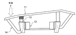
補強パイプ14を上述のように構成することにより、図3に示すように、FUPバー11の長手方向端部に荷重Fを受けた際にも、エネルギー吸収をしながらFUPバー11は後退していくが、補強パイプ14もFUPバー11と共に常にその形状を維持しながら後退することとなる。つまり、FUPバー11の長手方向端部に荷重Fを受けた際には、EA体13がFUPバー11とブラケット12との間で潰れ、FUPバー11及び補強パイプ14が後退することとなる。そのため、FUPバー11の長手方向端部がFUPバー11におけるEA体13との連結部を支点として車両後方向へ曲がることを抑制し、乗用車のトラック下部への過度な侵入を抑制することが可能となる。従って、本実施形態に係るFUP10によれば、他車とオフセット正面衝突した際に、相手車両の潜り込みを防止し、且つ衝突時のエネルギーを吸収して相手車両の速度を適切に減速せしめ、相手車両の潜り込み量を低く抑えることが可能となる。
以上、本発明の好適な実施形態について説明したが、本発明は上述の実施形態には限定されず他の様々な実施形態を採ることが可能である。
例えば、FUPバー11は、開断面形状(図示例では、車両後方向に開口する略U字状)には限定はされず、閉断面形状に形成されていても良い。
また、EA体13及び連結部材(補強パイプ)14は、円筒パイプには限定はされず、多角形筒パイプからなっても良い。
また、EA体13に穴やスリット等を設けて、EA体13を圧縮変形しやすい構造としても良い。
また、FUPバー11と補強パイプ14との間は、ボルト等による連結には限定はされず、FUPバー11と補強パイプ14との重なった部位において車両上下方向に延びるピンを介して連結しても良い。これは、オフセット正面衝突時など、FUPバー11の車幅方向片側のみが変形するような場合に、そのひずみをFUPバー11の曲がりで吸収するのではなく、FUPバー11と補強パイプ14との連結部によりFUPバー11の回転を許容して吸収するためである。
1 フレーム
10 フロントアンダーランプロテクタ(FUP)
11 FUPバー
12 ブラケット
13 エネルギー吸収体(EA体)
14 連結部材(補強パイプ)
20 規制部
24 第一直線部
25 湾曲部
26 第二直線部
10 フロントアンダーランプロテクタ(FUP)
11 FUPバー
12 ブラケット
13 エネルギー吸収体(EA体)
14 連結部材(補強パイプ)
20 規制部
24 第一直線部
25 湾曲部
26 第二直線部
Claims (3)
- 車両のフレームの下方に配設され、車幅方向に延びるFUPバーと、前記フレームに車幅方向に間隔を隔てて取り付けられ、前記フレームから下方に延びる一対のブラケットと、前記FUPバーと前記ブラケットとの間に車両前後方向と平行に延びるように介設され、圧縮変形することで衝突時のエネルギーを吸収するエネルギー吸収体と、一端部が前記FUPバーにおける前記エネルギー吸収体との連結部に連結され且つ中間部が車幅方向外側へ向かって曲げられ且つ他端部が前記FUPバーの長手方向端部に連結され、前記FUPバーの長手方向端部に荷重を受けた際に、前記FUPバーの長手方向端部が前記FUPバーにおける前記エネルギー吸収体との連結部を支点として車両後方向に回動しないように規制すると共に、前記FUPバーにおける前記エネルギー吸収体との連結部を車両後方向へ引っ張る連結部材とを備えたことを特徴とするフロントアンダーランプロテクタ。
- 前記エネルギー吸収体は、筒状に形成されており、前記連結部材は、前記エネルギー吸収体に挿入され、前記FUPバーにおける前記エネルギー吸収体との連結部を起点に車両後方向へ車両前後方向と平行に延びる第一直線部と、前記第一直線部に連続して形成され、車幅方向外側へ向かって曲がる湾曲部と、前記湾曲部に連続して形成され、車両前方向へ車両前後方向に対して車幅方向外側に傾斜して延び且つ前記FUPバーの長手方向端部に連結される第二直線部とを有する請求項1に記載のフロントアンダーランプロテクタ。
- 前記ブラケットに、前記FUPバーの長手方向端部に荷重を受けた際に、前記連結部材の車両後方向への移動を許容しつつ、前記連結部材の車幅方向内側への移動を規制する規制部が設けられる請求項1又は2に記載のフロントアンダーランプロテクタ。
Applications Claiming Priority (2)
| Application Number | Priority Date | Filing Date | Title |
|---|---|---|---|
| JP2011-111208 | 2011-05-18 | ||
| JP2011111208A JP5817209B2 (ja) | 2011-05-18 | 2011-05-18 | フロントアンダーランプロテクタ |
Publications (1)
| Publication Number | Publication Date |
|---|---|
| WO2012157437A1 true WO2012157437A1 (ja) | 2012-11-22 |
Family
ID=47176772
Family Applications (1)
| Application Number | Title | Priority Date | Filing Date |
|---|---|---|---|
| PCT/JP2012/061368 Ceased WO2012157437A1 (ja) | 2011-05-18 | 2012-04-27 | フロントアンダーランプロテクタ |
Country Status (2)
| Country | Link |
|---|---|
| JP (1) | JP5817209B2 (ja) |
| WO (1) | WO2012157437A1 (ja) |
Cited By (2)
| Publication number | Priority date | Publication date | Assignee | Title |
|---|---|---|---|---|
| DE102013012479A1 (de) * | 2013-07-26 | 2015-01-29 | GM Global Technology Operations, LLC (n.d. Ges. d. Staates Delaware) | Kraftfahrzeugstruktur mit Crashbox |
| WO2022005291A1 (en) * | 2020-07-02 | 2022-01-06 | Daf Trucks N.V. | A vehicle. |
Families Citing this family (2)
| Publication number | Priority date | Publication date | Assignee | Title |
|---|---|---|---|---|
| JP5915938B2 (ja) * | 2012-06-13 | 2016-05-11 | いすゞ自動車株式会社 | アンダーランプロテクタ構造 |
| CN103738284A (zh) * | 2013-12-19 | 2014-04-23 | 柳州乘龙专用车有限公司 | 一种半挂运输车侧护栏杆 |
Citations (3)
| Publication number | Priority date | Publication date | Assignee | Title |
|---|---|---|---|---|
| JPS60170248U (ja) * | 1983-12-28 | 1985-11-12 | 日産自動車株式会社 | バンパ構造 |
| JP2003072493A (ja) * | 2001-09-06 | 2003-03-12 | Hino Motors Ltd | アンダーランプロテクタ |
| JP2006001449A (ja) * | 2004-06-18 | 2006-01-05 | Kobe Steel Ltd | 乗用車用バンパー構造体 |
-
2011
- 2011-05-18 JP JP2011111208A patent/JP5817209B2/ja not_active Expired - Fee Related
-
2012
- 2012-04-27 WO PCT/JP2012/061368 patent/WO2012157437A1/ja not_active Ceased
Patent Citations (3)
| Publication number | Priority date | Publication date | Assignee | Title |
|---|---|---|---|---|
| JPS60170248U (ja) * | 1983-12-28 | 1985-11-12 | 日産自動車株式会社 | バンパ構造 |
| JP2003072493A (ja) * | 2001-09-06 | 2003-03-12 | Hino Motors Ltd | アンダーランプロテクタ |
| JP2006001449A (ja) * | 2004-06-18 | 2006-01-05 | Kobe Steel Ltd | 乗用車用バンパー構造体 |
Cited By (4)
| Publication number | Priority date | Publication date | Assignee | Title |
|---|---|---|---|---|
| DE102013012479A1 (de) * | 2013-07-26 | 2015-01-29 | GM Global Technology Operations, LLC (n.d. Ges. d. Staates Delaware) | Kraftfahrzeugstruktur mit Crashbox |
| US9333928B2 (en) | 2013-07-26 | 2016-05-10 | GM Global Technology Operations LLC | Motor vehicle structure with crash box |
| WO2022005291A1 (en) * | 2020-07-02 | 2022-01-06 | Daf Trucks N.V. | A vehicle. |
| NL2025975B1 (en) * | 2020-07-02 | 2022-03-08 | Daf Trucks Nv | A vehicle. |
Also Published As
| Publication number | Publication date |
|---|---|
| JP2012240511A (ja) | 2012-12-10 |
| JP5817209B2 (ja) | 2015-11-18 |
Similar Documents
| Publication | Publication Date | Title |
|---|---|---|
| JP6445687B2 (ja) | 自動車用のバンパー補強システム | |
| US10086784B2 (en) | Bumper unit for a motor vehicle | |
| JP5029328B2 (ja) | 自動車の前部車体構造 | |
| JP6459839B2 (ja) | 車両骨格構造 | |
| CN105992722B (zh) | 铁道车辆的碰撞能量吸收装置 | |
| KR101371838B1 (ko) | 차량 충돌 시 프론트 필러의 충돌 에너지 분산 구조 | |
| US7581781B2 (en) | Device for absorbing lateral forces during a side impact of a motor vehicle | |
| US20100140965A1 (en) | Deflector device for partially overlapping frontal collision of motor vehicles | |
| JP2009073368A (ja) | バンパ取付部構造 | |
| CN108016506B (zh) | 车辆机舱总成 | |
| JP6020203B2 (ja) | 車体前部構造 | |
| JP2009255705A (ja) | 自動車の前部構造 | |
| JP5817209B2 (ja) | フロントアンダーランプロテクタ | |
| JP2010503570A (ja) | 衝突により自動車のドアに向かって衝撃エネルギーが作用する際の乗員保護のための自動車用の装置 | |
| JP4314992B2 (ja) | 車体構造 | |
| JP2017047780A (ja) | 車両骨格構造 | |
| JP6540304B2 (ja) | 車輪連結構造及び自動車 | |
| JP4794985B2 (ja) | 車両用フレーム構造 | |
| JP2008120256A (ja) | 車両用衝撃吸収構造 | |
| WO2015119106A1 (ja) | 車体前部構造 | |
| CN111516569B (zh) | 一种能溃缩吸能的汽车后排座椅骨架 | |
| JP4479446B2 (ja) | 車体構造 | |
| JP2008189273A (ja) | フロントアンダランプロテクタ | |
| JP4450172B2 (ja) | 自動車のペリメータフレーム構造 | |
| KR101252208B1 (ko) | 측면충돌에 대한 강성이 보강된 차량용 도어 |
Legal Events
| Date | Code | Title | Description |
|---|---|---|---|
| 121 | Ep: the epo has been informed by wipo that ep was designated in this application |
Ref document number: 12785965 Country of ref document: EP Kind code of ref document: A1 |
|
| NENP | Non-entry into the national phase |
Ref country code: DE |
|
| 122 | Ep: pct application non-entry in european phase |
Ref document number: 12785965 Country of ref document: EP Kind code of ref document: A1 |