WO2012157430A1 - 環状軌道輪モジュール及びアキシャルローラベアリング - Google Patents
環状軌道輪モジュール及びアキシャルローラベアリング Download PDFInfo
- Publication number
- WO2012157430A1 WO2012157430A1 PCT/JP2012/061239 JP2012061239W WO2012157430A1 WO 2012157430 A1 WO2012157430 A1 WO 2012157430A1 JP 2012061239 W JP2012061239 W JP 2012061239W WO 2012157430 A1 WO2012157430 A1 WO 2012157430A1
- Authority
- WO
- WIPO (PCT)
- Prior art keywords
- annular
- track
- axial roller
- plate
- race
- Prior art date
- Legal status (The legal status is an assumption and is not a legal conclusion. Google has not performed a legal analysis and makes no representation as to the accuracy of the status listed.)
- Ceased
Links
Images




Classifications
-
- F—MECHANICAL ENGINEERING; LIGHTING; HEATING; WEAPONS; BLASTING
- F16—ENGINEERING ELEMENTS AND UNITS; GENERAL MEASURES FOR PRODUCING AND MAINTAINING EFFECTIVE FUNCTIONING OF MACHINES OR INSTALLATIONS; THERMAL INSULATION IN GENERAL
- F16C—SHAFTS; FLEXIBLE SHAFTS; ELEMENTS OR CRANKSHAFT MECHANISMS; ROTARY BODIES OTHER THAN GEARING ELEMENTS; BEARINGS
- F16C19/00—Bearings with rolling contact, for exclusively rotary movement
- F16C19/22—Bearings with rolling contact, for exclusively rotary movement with bearing rollers essentially of the same size in one or more circular rows, e.g. needle bearings
- F16C19/30—Bearings with rolling contact, for exclusively rotary movement with bearing rollers essentially of the same size in one or more circular rows, e.g. needle bearings for axial load mainly
-
- F—MECHANICAL ENGINEERING; LIGHTING; HEATING; WEAPONS; BLASTING
- F16—ENGINEERING ELEMENTS AND UNITS; GENERAL MEASURES FOR PRODUCING AND MAINTAINING EFFECTIVE FUNCTIONING OF MACHINES OR INSTALLATIONS; THERMAL INSULATION IN GENERAL
- F16C—SHAFTS; FLEXIBLE SHAFTS; ELEMENTS OR CRANKSHAFT MECHANISMS; ROTARY BODIES OTHER THAN GEARING ELEMENTS; BEARINGS
- F16C33/00—Parts of bearings; Special methods for making bearings or parts thereof
- F16C33/30—Parts of ball or roller bearings
- F16C33/58—Raceways; Race rings
- F16C33/60—Raceways; Race rings divided or split, e.g. comprising two juxtaposed rings
Definitions
- the present invention provides, for example, a support structure that supports the main shaft of a wind power generator, a cutter disk that rotates a shield excavator, a support structure that supports a cutter frame while receiving a thrust load, or a power excavator, a crane, and the like.
- the present invention relates to an annular race that is mounted on an axial roller bearing that receives an axial load as used in a support structure that is supported by a lower frame.
- a shield excavator has been put to practical use as an excavator for constructing various shield mine such as water and sewage tunnels, subway tunnels, etc. by the shield construction method.
- Such a huge excavator is rotatably installed, and an axial roller bearing is used to support it.
- Axial roller bearings are used in construction machines such as power shovels and cranes.
- the axial roller bearings used in these machines need to support a considerably large load in the axial direction, and the radius of the roller bearing itself is considerably large because of the size of the object to be supported.
- an axial roller bearing that supports a load in the axial direction (or thrust direction) includes, for example, a pair of race rings such as an upper race ring 550 and a lower race ring 560, and the pair of the race rings, as shown in FIG.
- the plurality of rollers 510 disposed between the raceway rings and a holder 520 that holds the plurality of rollers 510, each of which is formed of a single component (for example, Patent Document 1). checking).
- the applied apparatus is large, and the axial roller bearing 500 has a very large diameter.
- the load applied to itself is considerably large, each of the rollers 510 held therein is considerably small, and as shown in FIG. 10, the outer diameter of the axial roller bearing 500 is large.
- the upper and lower race rings 550 and 560 and the cage 520 constituting the bearing have a unique structure that is different from a normal bearing in that the widths of the bearing rings 550 and 560 and the cage 520 are relatively small. Therefore, the upper and lower race rings 550 and 560 on which a large number of rollers 510 roll are also reduced in thickness and thickness with respect to the large diameter, and are easily deformed.
- the bearing ring is usually formed integrally with the bearing raceway portion and the other portions that are in rolling contact with the roller, the entire raceway is heat-treated together. Since there is no way to distinguish unnecessary parts, there is a problem of increased costs such as energy loss. Especially when molding large-diameter races, it is necessary to ensure strength. The part where the work such as the heat treatment is unnecessary becomes large, and the cost as a whole is increased, which is a further problem.
- the present invention solves the problems of the prior art as described above, and the technical problem of the present invention, that is, the object of the present invention, is a simple divided structure, easy to handle, and reduces material loss.
- An object of the present invention is to provide an annular race ring module and an axial roller bearing that can be produced with low efficiency.
- the invention according to claim 1 is an axial roller comprising a pair of annular races positioned opposite to each other and a plurality of axial rollers disposed at equal intervals in the circumferential direction between the pair of annular races.
- the track segments of the ring-shaped raceway plate have a large-diameter arc end on the outer peripheral side and the large on the inner peripheral side.
- the above-mentioned problem is further solved by presenting a fan-shaped shape including a small-diameter arc-shaped end portion concentric with the radial arc-shaped end portion and linear end portions extending radially in both circumferential ends.
- the linear end of the track segment is formed at an angle that intersects the axis of the axial roller.
- the annular race module of the invention according to claim 4 has a plurality of angles at which the linear end of the track segment intersects the axis of the axial roller.
- the annular race ring module of the invention according to claim 5 has an annular concave groove in which the annular race plate is mounted.
- the annular track ring module of the invention according to claim 6 solves the above-described problem by the annular base plate being constituted by a plurality of divided base segments. It is a thing.
- the annular track ring module of the invention according to claim 7 is arranged so that the dividing line of the annular track plate is not located on the same straight line as the dividing line of the annular base plate.
- An axial roller bearing according to an eighth aspect of the present invention has the above-described problem because one or both of the annular race rings are constituted by the annular race ring module according to any one of claims 1 to 7. It has been solved.
- the axial roller bearing of the invention according to claim 9 is held by an annular retainer provided between the annular races, and the retainer is By being composed of a plurality of divided cage segments, the above-described problems are further solved.
- the invention according to claim 1 is an axial roller bearing comprising a pair of annular races positioned opposite to each other and a plurality of axial rollers disposed at equal intervals in the circumferential direction between the pair of annular races.
- the track segments are relatively small in size and are reasonably sized. Compared to large diameter and narrow track rings, large-scale machining dedicated to each process in each work process such as cutting and heat treatment. Each process can be performed using a standard size device that is versatile without the need for equipment or processing equipment, and each process is relatively small.
- the work itself becomes simple, and the work load such as packing and transfer is reduced and the work burden is reduced, reducing the precision work as before in manufacturing.
- the yield can be greatly improved, and the handling work such as transportation and transfer can greatly reduce the work of consuming nerves so that deformation does not occur, and the workability can be greatly improved.
- the annular track plate by configuring the annular track plate with divided track segments, it is possible to take the material to cut out arcuate strip-shaped track segments side by side, instead of cutting out the circular track member from the raw material, For example, it is possible to effectively reduce the generation of materials that must be discarded as traces, such as disc-shaped waste materials that were previously generated when an annular member was punched, and the raw materials can be used effectively. . Furthermore, if a part of the annular track plate is damaged, it is possible to use it again by replacing only the damaged part. Therefore, only small parts need to be replaced in maintenance work. The waste of the material such as the entire waste is eliminated, and replacing part of the parts can greatly reduce the loss of material. In addition, even in maintenance work, the work of consuming nerves to handle large parts in parts replacement work As a result, the workability in maintenance work can be greatly improved.
- the ring segment of the invention according to claim 2 has a track segment of the ring track plate having a large-diameter arc end on the outer peripheral side and a large diameter on the inner peripheral side, respectively. Machining by combining each arc segment with a circular arc and a straight line by exhibiting a fan-shaped shape with arc-shaped ends and concentric small-diameter arc-shaped ends and linear ends extending radially at both ends in the circumferential direction. Therefore, the machining operations such as the punching and cutting of the track segments can be simplified, and the machining operations can be performed easily and at low cost without requiring an expensive machine tool.
- the annular race module of the invention according to claim 3 is formed at an angle at which the linear end of the track segment intersects the axis of the axial roller,
- the contact line between the track segments and the contact surface of the axial roller raceway surface does not become parallel, and the contact line does not get over the step when the axial roller rolls on the annular track plate.
- the annular race module of the invention according to claim 4 has a plurality of straight lines having an angle at which the linear end of the track segment intersects the axis of the axial roller.
- the contact portions between the track segments are formed in a zigzag shape with a small pitch, and the contact line between the contact portion and the track surface of the axial roller is not on the same straight line.
- the risk of damaging the rolling surface of the axial roller or the surface of the annular raceway plate is significantly reduced, and it is used for a longer service life. It is possible.
- the pitch of the zigzag butt portion generated between the track segments is reduced, the level difference that may occur between adjacent track segments is made smaller, and collisions may occur on the surfaces of the axial roller and the annular track plate. Can be further reduced.
- the annular race ring module of the invention according to claim 5 forms an annular concave groove for mounting the annular race plate.
- the annular raceway ring of the axial roller bearing is required to have a certain level of both material cost and machining cost because the hardness and surface machining accuracy are required, and the whole Because it is composed of an annular base plate part that requires a desired size to maintain its strength but does not require special processing and may be a general-purpose material, even a large product as a whole is heat treated, precision Processes such as cutting work should be applied only to those parts that require these treatments, minimizing the processing work, and only parts that maintain strength. It can be the like reduce the material cost by using an inexpensive material, as a whole product, while maintaining its function, significantly reduces the raw material cost and manufacturing cost.
- the annular base plate is constituted by a plurality of divided base segments. Not only plates but also annular base plates are segmented, and the processing of each base segment is simplified and streamlined by eliminating the work of consuming nerves when handling large-diameter items, and collecting less material Therefore, the annular base plate can be efficiently executed without waste using a general-purpose machine without the need for a dedicated machine in the manufacturing process, and the raw material is effectively used and wasted. Can be greatly reduced.
- the annular track ring module of the invention according to claim 7 is mounted so that the dividing line of the annular track plate is not located on the same straight line as the dividing line of the annular base plate.
- the annular raceway plate and the annular base plate constituting the raceway of the large-diameter axial roller bearing are configured by a plurality of segments to prevent the strength reduction of the annular raceway ring, and the axial roller has a stepped raceway surface. Prevents noise increase and wear on the axial roller rolling surface or raceway surface that may occur when rolling. It can be.
- An axial roller bearing according to an eighth aspect of the present invention is provided with the annular raceway module according to any one of the first to seventh aspects, and is similar to the annular raceway module according to any one of these claims.
- Axial roller bearings having the following effects can be formed, and an annular raceway constituted by a plurality of segments as in the present invention is applied to a conventional axial roller bearing.
- the roller bearing it can be improved sequentially with the high production efficiency and excellent maintainability as in the present invention.
- the axial roller bearing of the invention according to claim 9 is held by an annular retainer provided between the annular races. Because it is composed of a plurality of divided cage segments, all the parts that make up the axial roller bearing are segmented and made up of small parts, so the entire axial roller bearing has a simple structure, It is excellent in workability, can be manufactured with high yield and efficiency, and if part of the cage is damaged, it can be used again by replacing only the damaged part. Can be greatly improved.
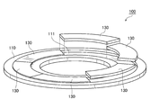
- FIG. 1 is an overall perspective view of an annular race module that is a first embodiment of the present invention.
- FIG. FIG. 2 is a partially exploded perspective view of the annular race module shown in FIG. 1.
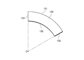
- FIG. 2 is a plan view of a track segment used in the annular track ring module shown in FIG. 1.
- the partially exploded perspective view of the annular track ring module which is 2nd Example of this invention.
- the partial exploded perspective view of the annular track ring module which is the 3rd example of the present invention.
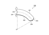
- FIG. 7 is a plan view of a track segment used in the annular track ring module shown in FIG. 6.
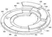
- the whole perspective view of the annular track ring module which is the 4th example of the present invention.
- FIG. 9 is a partially exploded perspective view of the annular race module shown in FIG. 8.
- the present invention is used for an axial roller bearing provided with a pair of annular races positioned opposite to each other and a plurality of axial rollers disposed at equal intervals in the circumferential direction between the pair of annular races.
- An annular race ring module comprising an annular race plate composed of a plurality of race segments divided in the circumferential direction and / or radial direction, and having a simple divided structure and being easy to handle. As long as the material can be produced efficiently with little loss of material, the specific mode is not particularly limited.
- the material of the annular race plate that forms the annular race ring can withstand high loads such as large-diameter bearings, has high processing accuracy and high wear resistance, as used in ordinary roller bearings. If so, high / medium carbon alloy steel, carburized steel, bearing steel, corrosion-resistant bearing steel, carbon steel, etc. may be used. Moreover, in order to improve the wear resistance in rolling friction with the axial roller, it is preferable to subject the surface to a curing treatment such as thermosetting, impregnation curing, and induction hardening. Since the material of the base plate that supports the annular track plate does not require characteristics such as direct wear resistance, a rolled steel material or a carbon steel material used for general structural members may be used.
- track segments or the base segments may be mounted side by side at the location where the axial rollers are installed, but the segments are welded together so as to improve the flatness of the surface or improve the strength. You may join by methods, such as brazing.
- the way to divide the annular track plate it is appropriate to divide in the circumferential direction when the diameter is large and the width is narrow, but when the annular track plate is wide in the radial direction, it is not the circumferential direction but the radial direction.
- a fan shape is preferable when using the same segment, but when forming a larger bearing, it is formed in a shape such as a square, a rectangle, etc. It may be formed by spreading tiles.
- the shape of the side end portion may be an arc shape or a spiral shape in addition to a straight line or a zigzag shape, but care must be taken not to cause a step between adjacent segments.
- the adjacent track segments may be arranged without a gap, or may be arranged with a gap forming a narrow groove through which the lubricant flows.
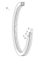
- FIGS. 1 to 3 is an overall perspective view of an annular race module 100 according to a first embodiment of the present invention
- FIG. 2 is a partially exploded perspective view of the annular race module 100 shown in FIG. 1
- FIG. It is a top view of the track segment 120 used for the annular track ring module 100 shown in FIG.
- the annular race module 100 includes an annular base plate 110 that constitutes a base portion and maintains the strength of the bearing, and an annular concave groove formed in the annular base plate 110.
- An annular track plate 120 is mounted.
- the annular track plate 120 is divided into a plurality of track segments 130, and in the first embodiment, is composed of six track segments 130.
- the width of the track segment 130 corresponds to the axial roller rolling range according to the axial length of the axial roller rolling on the surface of the annular track plate 120 formed by arranging the track segments 130 side by side. Width.
- the annular base plate 110 and the track segment 130 are formed of different materials.
- the track segment 130 uses high-carbon chromium steel having excellent wear resistance, and the surface on which the axial roller rolls is processed with high accuracy. Appropriate curing treatment is performed.
- the annular base plate 110 supports the axial load when the bearing is completed, so that the annular base plate 110 is larger in both width and thickness than the annular race plate 120. Therefore, it is formed of a relatively inexpensive rolled steel material. Note that the size and strength required for the annular base plate 110 depend on the strength of the target part to which the axial roller bearing to be formed is attached, and if the strength of the attachment part is not high, it is necessary to provide a structure having a considerably high strength.
- the annular base plate 110 can be made small. In some cases, the annular base plate 110 may be omitted and only the annular track plate 120 may be used.
- the size of the track segment 130 is determined in principle based on the pressing force applied from the axial roller, the rolling speed of the axial roller, and the like.
- each track segment 130 has a fan-shaped shape including a large-diameter outer peripheral arc-shaped portion 131, a small-diameter inner peripheral arc-shaped portion 132, and linear end portions 133 on both sides.
- each segment can be made to a size suitable for processing, there is no need to prepare a special large heat treatment furnace or machine tool, and it should be used in a heat treatment furnace or machine tool that exists relatively close to you. As a result, it is possible to carry out work on materials that are easy to work without extending the usual work without having to work unfamiliar with large-sized materials, thus improving the work efficiency of production work. can do.
- the annular race ring module 100 according to the first embodiment of the present invention obtained as described above includes an annular race plate 120 composed of a plurality of race segment 130 in which the annular race ring is divided in the circumferential direction.
- the individual track segments 130 can be divided into reasonable segments suitable for processing and processing, improving workability in processing and processing operations and greatly improving manufacturing efficiency.
- troublesome work can be greatly reduced and workability can be improved.
- efficient material removal is possible, and raw materials can be used to the maximum extent possible. The effect is enormous, for example, the efficiency of maintenance work can be improved without handling easily deformable parts.
- FIG. 4 is a partially exploded perspective view of an annular track module 200 according to the second embodiment of the present invention
- FIG. 5 is a plan view of a track segment 230 used in the annular track module 200 shown in FIG. is there.
- the annular raceway module 200 of the second embodiment differs from the annular raceway module 100 of the first embodiment only in the shape of the raceway segment 230, but there is no particular difference in the other structures.
- the other common items are simply denoted by the common reference numerals of the 200th generation in the last two digits, and detailed description thereof is omitted.
- the annular track ring module 200 of the second embodiment is the same as the annular track ring module 100 of the first embodiment in that it includes six track segments 230.
- the track segment 230 provided in the second embodiment intersects with a large-diameter outer peripheral arc-shaped portion 231, a small-diameter inner peripheral arc-shaped portion 232, and a straight line extending radially from the center of the annular track plate at one end on the side surface at an angle X. It has a feature that it has a linear end portion 233 that has a linear end portion 233 at an angle that can come into contact with the other end, and these track segments 230 are arranged side by side.
- a butt portion is formed between the adjacent track segments 230 so as to intersect the aforementioned radial straight line.
- the axial roller that rolls on the raceway surface of the annular raceway plate 220 has its axis radially from the center of the annular raceway plate 220, and the contact between the rolling surface of the axial roller plate and the surface of the annular raceway plate 120. Since the line is a radial straight line similar to the axis, the abutting portions between the track segments 230 do not become the same line as the contact line of the axial roller but intersect. As a result, even when the axial roller rolls on the annular track plate 220 and moves from the previous annular segment 230 to the next annular segment 230, the axial roller can smoothly roll and move without receiving an impact. It becomes possible.
- the axial roller and the linear end portion 233 of the track segment 230 do not collide with each other in this portion, so that it is possible to prevent a large noise from being generated, and the end portion of the track segment 230 and the rolling surface of the axial roller can be prevented.
- the risk of damage can be greatly reduced and these can be extended in life.
- FIG. 6 is a partially exploded perspective view of an annular race module 300 according to a third embodiment of the present invention.
- FIG. 7 is a plan view of a race segment 330 used in the annular race module 300 shown in FIG. is there.
- the annular race ring module 300 of the third embodiment is different from the annular race ring module 200 of the second embodiment only in the shape of the race segment 330, but there is no particular difference in the other structures.
- the other common items are simply denoted by the same reference numerals of the 300th generation in the last two digits, and detailed description thereof is omitted.
- the annular track ring module 300 of the third embodiment is the same as the annular track ring module 200 of the second embodiment in that it includes six track segments 330.
- the track segment 330 provided in the third embodiment has a large-diameter outer peripheral arc-shaped portion 331, a small-diameter inner peripheral arc-shaped portion 332, and a straight line and an angle Y extending radially from the center of the annular track plate 320 at one end on the side surface side.
- V-shaped linear end portion 333, 334 composed of two intersecting straight lines, and the other end has the same reverse V-shaped linear end portion 333 at an angle capable of contacting with the one end described above, If the track segments 330 are arranged side by side to form the annular track plate 320, the V-shaped crossing with the above-described radial straight line is formed between the adjacent track segments 330. A shaped butted portion will be formed.
- the axial roller smoothly rolls and moves without receiving an impact. Therefore, the possibility of damaging the end portion 333 of the track segment 330 and the rolling surface of the axial roller can be further reduced, and the life can be extended.
- the circumferential dimension of the butting portion is reduced to make the step between the two smaller, and even if a step occurs, the axial roller runs on two places instead of one. Therefore, the impact generated on the end surface of the track segment 330 or the rolling surface of the axial roller can be reduced sufficiently.
- the same angle may be sufficient as the angle Y which two linear edge parts form, and a different angle may be sufficient as it.
- the annular race ring module 200 of the second embodiment and the annular race ring module 300 of the third embodiment formed as described above, in addition to the effects exhibited by the annular race ring module 100 of the first embodiment described above, are track segments. Since the linear end portions 233, 333, and 334 of the 230 and 330 are formed at an angle that intersects the axis of the axial roller, the axial roller smoothly rolls and moves on the raceway surfaces of the annular raceway plates 220 and 320. The noise generated during rolling can be reduced, and the life of the axial roller and the annular track plates 220 and 320 can be extended.
- FIG. 8 is an overall perspective view of the annular race ring module 400 according to the fourth embodiment of the present invention
- FIG. 9 is a partially exploded perspective view of the annular race ring module 400 shown in FIG.
- the annular race ring module 400 of the fourth embodiment differs from the annular race ring module 100 of the first embodiment only in the structure of the base plate 410, but there is no particular difference in the other structures. For other common items, only the 400th number common to the last two digits is attached, and the detailed description is omitted.
- the annular race ring module 400 of the fourth embodiment is characterized in that the annular base plate 410 that holds the annular race plate 420 is also divided into a plurality of base segments 440.
- the annular raceway plate has a fan-shaped shape divided in the circumferential direction, but in this embodiment, the annular raceway plate 420 is constituted by the raceway segments 430 and the annular base plate 410 is also formed. As shown in FIGS. 8 and 9, for example, the base segment 440 is divided into a plurality of pieces in the circumferential direction.
- the large-diameter base plate 410 need not be handled as being integrally formed with a large diameter. Since each segment is a relatively small segment that is reasonably sized for processing and transfer, the manufacturing and handling are simplified and efficient as in the case of segmenting the annular track plate 420. Can be achieved.
- the abutting portions of the respective segments that is, the dividing lines of the respective plates are not positioned on the same straight line. If both are positioned on the same straight line, the track segment 430 and the base segment 440 are separated at the same position, and are easily separated after assembly, and the annular raceway module 400 assembled with both can be handled as a unit. Therefore, it becomes inconvenient in handling.
- the dimensional error of the base segment 440 and the dimensional error of the track segment 430 appear to overlap at the same position, and the step generated between the adjacent track segments 430 becomes large, so that the axial roller is in the annular track plate 420.
- the butt portions should be positioned so as not to overlap. In this regard, even if the angle of the linear end 433 of the track segment 430 is set to a different angle from the angle of the linear end 443 of the base segment 440, this occurs when the butted portion is positioned close to the track segment 430. Thus, it is possible to eliminate the possibility that the butted portions are overlapped on the same straight line and are easily disassembled, and that the above-described dimensional errors are accumulated to cause a step.
- annular raceway module 400 of the fourth embodiment described above the annular base plate 410 and the annular raceway plate 420 are respectively segmented to simplify the production and maintenance of the component parts and improve the efficiency of the production work.
- the target of segmentation is not limited to these two types of parts, and the cage that holds the axial roller can be divided and segmented into a large number of parts to improve the efficiency of production and maintenance. it can.
- an annular retainer can also be segmented by dividing it into fan-shaped parts such as the above-mentioned track segments and assembling them integrally at the final stage of bearing manufacture.
- the annular race ring module 400 of the fourth embodiment formed as described above has a base plate 410 in addition to the effects exhibited by the annular bearing modules 100, 200, and 300 of the first to third embodiments described above. Since the base plate 410 is made up of a plurality of divided base segments 440, each of the segments is relatively small in size and can be easily processed so as to manufacture an integral large-diameter part. In addition to eliminating precision work in manufacturing, the yield can be greatly improved. In handling and transportation, the work that consumes nerves as before has been greatly reduced, significantly improving workability. can do.
- the annular base plate 410 instead of cutting out the annular base plate 410 from the raw material, it is possible to take the material so as to cut out the arc-shaped strip-shaped base segments 440 side by side, so the generation of a material that must be discarded as a trace is generated.
- the raw material can be effectively utilized by greatly reducing, and when a part of the annular base plate 410 is damaged, it is possible to use it again by replacing only the base segment 440 at the damaged part. Therefore, even in maintenance work, there is no waste of material such as discarding entire large parts, and replacing parts of parts can greatly reduce material loss, and work that consumes nerves in maintenance work The effect is enormous, such as a significant reduction.
- annular ring module 110 210, 310, 410 ... annular base plate 111, 211, 311, 411 ... concave groove 120, 220, 320, 420 ... annular race Plates 130, 230, 330, 430 ... Track segments 131, 231, 331 ... Outer arcuate parts 132, 232, 332 ... Inner arcuate parts 133, 233, 333, 334 ...
Landscapes
- Engineering & Computer Science (AREA)
- General Engineering & Computer Science (AREA)
- Mechanical Engineering (AREA)
- Rolling Contact Bearings (AREA)
Abstract
簡易な分割構造であって取り扱いが容易で、材料ロスを少なく効率的に生産可能な環状軌道輪モジュールを提供すること。 相対向して位置する一対の環状軌道輪とこれら一対の環状軌道輪の間に周方向に等間隔に配設された複数のアキシャルローラとを備えたアキシャルローラベアリングに使用される環状軌道輪モジュール(100)であって、環状軌道輪が周方向及び/又は径方向に分割された複数の軌道セグメント(130)から構成される環状軌道プレート(120)を備えている環状軌道輪モジュール(100)。
Description
本発明は、例えば、風力発電機の主軸を支持する支持構造、シールド掘削機の回転するカッターディスク、カッタフレームのスラスト荷重を受けつつ支持する支持構造、又はパワーショベル、クレーン等において上部回転部を下部フレームに支持する支持構造などに使用されるような軸方向荷重を受けるアキシャルローラベアリングに装備される環状軌道輪に関するものである。
従来から、上下水道用トンネル、地下鉄用トンネル等の各種のシールド坑をシールド工法により構築するための掘削装置としてシールド掘削機が実用化されていて、このようなシールド掘削機では先端にカッターディスクのような巨大な掘削装置が回転自在に設置されており、これを支持するためにアキシャルローラベアリングが使用されている。
また、パワーショベル、クレーンのような建設機械では、自走機構を備えた下部構造に対し、ショベルアーム、ブームを備えて下部機構に対して回転自在に設置される上部機構を支持するために、アキシャルローラベアリングが使用されている。
これらの機械に使用されるアキシャルローラベアリングは、アキシャル方向に相当に大きな荷重を支持する必要があるとともに、その支持する対象の大きさゆえに、ローラベアリング自体の半径が相当に大きいものである。
また、パワーショベル、クレーンのような建設機械では、自走機構を備えた下部構造に対し、ショベルアーム、ブームを備えて下部機構に対して回転自在に設置される上部機構を支持するために、アキシャルローラベアリングが使用されている。
これらの機械に使用されるアキシャルローラベアリングは、アキシャル方向に相当に大きな荷重を支持する必要があるとともに、その支持する対象の大きさゆえに、ローラベアリング自体の半径が相当に大きいものである。
通常、アキシャル方向(若しくはスラスト方向)の荷重を支持するアキシャルローラベアリングは、図10に示されるように、例えば、上側軌道輪550及び下側軌道輪560のような一対の軌道輪と、当該一対の軌道輪の間に配置される複数のローラ510と、これら複数のローラ510を保持する保持器520とから構成されていて、それぞれは、単独の部品で形成されている(例えば、特許文献1を参照のこと)。
ところが、本願発明が前提とするような大型のアキシャルローラベアリング500の場合には、適用される装置が大型であり、アキシャルローラベアリング500もその径は非常に大径となって、アキシャルローラベアリング500自体に印加される荷重も相当大きくなるが、そこに保持されるそれぞれのローラ510自体はかなり小さく、図10に示されるように、アキシャルローラベアリング500の外径が大径となる割には、ベアリングを構成する上下の軌道輪550、560や保持器520の幅が相対的に小さい点というにおいて、通常のベアリングとは異なる、独特の構造を備えている。
したがって、多数のローラ510がその間を転動する上下の軌道輪550、560も、径が大径である割に板幅、板厚が薄く、変形し易いものとなってしまい、通常のベアリングに使用される軌道輪のように全体を一体として成形すると、その運搬、装着作業時などに変形、破損などが生起し易く、取り扱いに細心の注意を要するものであり、作業者の負担が大きいという問題があった。
また、全体構造としてそのような変形し易い構造であるため、製作においても精度を上げることが難しく加工においても細心の注意を払う必要があり、歩留まりも上がらず作業性を向上し難いという問題があった。
したがって、多数のローラ510がその間を転動する上下の軌道輪550、560も、径が大径である割に板幅、板厚が薄く、変形し易いものとなってしまい、通常のベアリングに使用される軌道輪のように全体を一体として成形すると、その運搬、装着作業時などに変形、破損などが生起し易く、取り扱いに細心の注意を要するものであり、作業者の負担が大きいという問題があった。
また、全体構造としてそのような変形し易い構造であるため、製作においても精度を上げることが難しく加工においても細心の注意を払う必要があり、歩留まりも上がらず作業性を向上し難いという問題があった。
さらに、通常、軌道輪はローラと転がり接触するベアリング軌道部分とそれ以外の部分とが一体で形成されているため軌道輪全体をまとめて熱処理することとなり、ベアリング軌道と反対側の面など熱処理の不要な箇所についても区別することなく処理作業を行なわざるを得ないため、エネルギーロスなどコストアップとなるという問題があり、特に大径の軌道輪を成形する場合には、強度を確保する必要上、熱処理などの作業が不要である部分が大きくなり、全体としてかなりのコストとなってしまい、一層問題であった。
また、従前、軌道輪を作成するものとして、比較的大判の板状の材料から円環状の素材を打ち抜き、その後熱処理等の加工を施して軌道輪を形成するものもあったが、このような軌道輪はもっぱら小型のベアリングにおいて実行されるものであって大径のベアリングに適用するには好適なものではなく、また、抜き跡として円板状の材料が残るなど廃棄される材料も多くなり、材料の有効利用が図れず高コストとなるという問題があった。
本発明は、前述したような従来技術の問題点を解決するものであって、本発明の技術的課題、すなわち本発明の目的は、簡易な分割構造であって取り扱いが容易で、材料ロスを少なく効率的に生産可能な環状軌道輪モジュール及びアキシャルローラベアリングを提供することにある。
本請求項1に係る発明は、相対向して位置する一対の環状軌道輪とこれら一対の環状軌道輪の間に周方向に等間隔に配設された複数のアキシャルローラとを備えたアキシャルローラベアリングに使用される環状軌道輪モジュールであって、前記環状軌道輪が周方向及び/又は径方向に分割された複数の軌道セグメントから構成される環状軌道プレートを備えていることにより、前述した課題を解決したものである。
請求項2に係る発明の環状軌道輪モジュールは、請求項1に係る発明の構成に加えて、前記環状軌道プレートの軌道セグメントが、それぞれ外周側に大径弧状端部と内周側に前記大径弧状端部と同心円状の小径弧状端部と周方向両端に径方向に伸長する直線状端部とを備える扇面形状を呈していることにより、前述した課題をさらに解決したものである。
請求項3に係る発明の環状軌道輪モジュールは、請求項2に係る発明の構成に加えて、前記軌道セグメントの直線状端部が、前記アキシャルローラの軸線と交差する角度に形成されていることにより、前述した課題をさらに解決したものである。
請求項4に係る発明の環状軌道輪モジュールは、請求項2又は請求項3に係る発明の構成に加えて、前記軌道セグメントの直線状端部が、前記アキシャルローラの軸線と交差する角度の複数の直線状端部から形成されていることにより、前述した課題をさらに解決したものである。
請求項5に係る発明の環状軌道輪モジュールは、請求項1乃至請求項4のいずれかに係る発明の構成に加えて、前記環状軌道輪が、前記環状軌道プレートを装着する環状の凹溝を形成した環状ベースプレートを備えていることにより、前述した課題をさらに解決したものである。
請求項6に係る発明の環状軌道輪モジュールは、請求項5に係る発明の構成に加えて、前記環状ベースプレートが、分割された複数のベースセグメントにより構成されていることにより、前述した課題を解決したものである。
請求項7に係る発明の環状軌道輪モジュールは、前記請求項6に係る発明の構成に加えて、前記環状軌道プレートの分割線が、前記環状ベースプレートの分割線と同一直線上に位置しないように装着されていることにより、前述した課題をさらに解決したものである。
請求項8に係る発明のアキシャルローラベアリングは、前記環状軌道輪の一方又は双方が請求項1乃至請求項7のいずれかに記載の環状軌道輪モジュールで構成されていることにより、前述した課題を解決したものである。
請求項9に係る発明のアキシャルローラベアリングは、請求項8に係る発明の構成に加えて、前記アキシャルローラが、前記環状軌道輪の間に設けた環状の保持器により保持され、該保持器が分割された複数の保持器セグメントより構成されていることにより、前述した課題をさらに解決したものである。
請求項1に係る発明は、相対向して位置する一対の環状軌道輪とこれら一対の環状軌道輪の間に周方向に等間隔に配設された複数のアキシャルローラとを備えたアキシャルローラベアリングに使用される環状軌道輪モジュールであって、環状軌道輪が周方向及び/又は径方向に分割された複数の軌道セグメントから構成される環状軌道プレートを備えていることにより、おのおのの分割された軌道セグメントはサイズも相対的に小さく手頃な大きさとなり、大径、細幅の軌道輪の場合と比べ、切削加工、熱処理などの各作業工程において、それぞれの工程のために専用の大型の加工装置若しくは処理装置を要することなく汎用性のある標準的なサイズの装置を使用して各工程を遂行でき、しかもそれぞれの工程については比較的小型であり変形の虞も小さいため作業自体も簡便となり、さらに、梱包、移送などの作業についても変形の虞が軽減されて作業負担が軽減されるため、製造における従前のような精密な作業を軽減して歩留まりを大幅に改善できるとともに、運搬、移送などの取り扱いにおいても、従前のような、変形が生じないように神経を消耗する作業を大きく低減して、作業性を大きく改善することができる。
また、環状軌道プレートを分割した軌道セグメントにより構成したことにより、原材料から円環状の軌道部材を切り出すのではなく、弧状短冊状の軌道セグメントを並べて切り出すように材料取りすることが可能となるため、例えば環状部材を打ち抜いたときに従前発生していた円板状の廃材のような、抜き跡として廃棄せざるを得ない材料の発生を大幅に軽減して、原材料を有効に活用することができる。
さらに、環状軌道プレートの一部が損壊した場合には、損壊した箇所のみ交換すれば再び使用することが可能となるため、保守作業においても、小型の部品を交換するのみでよく、大型の部品を丸ごと廃棄するような材料の無駄がなくなり、一部分の部品を交換することで材料のロスを大幅に低減でき、しかも、保守作業においても、部品交換作業における大型の部品を取り扱う神経の消耗する作業を大幅に低減するなど、保守作業における作業性を大幅に改善することができる。
さらに、環状軌道プレートの一部が損壊した場合には、損壊した箇所のみ交換すれば再び使用することが可能となるため、保守作業においても、小型の部品を交換するのみでよく、大型の部品を丸ごと廃棄するような材料の無駄がなくなり、一部分の部品を交換することで材料のロスを大幅に低減でき、しかも、保守作業においても、部品交換作業における大型の部品を取り扱う神経の消耗する作業を大幅に低減するなど、保守作業における作業性を大幅に改善することができる。
請求項2に係る発明の環状軌道輪モジュールは、請求項1に係る発明が奏する効果に加えて、環状軌道プレートの軌道セグメントが、それぞれ外周側に大径弧状端部と内周側に大径弧状端と同心円状の小径弧状端部と周方向両端に径方向に伸長する直線状端部とを備える扇面形状を呈するものであることにより、それぞれの軌道セグメントを円弧と直線とを組み合わせた加工の容易な形状としたため、軌道セグメントの打ち抜き、切削などの加工作業を簡便化して、高価な工作機械を要することなく、加工作業を簡便にしかも低コストで実行することができる。
請求項3に係る発明の環状軌道輪モジュールは、請求項2に係る発明が奏する効果に加えて、軌道セグメントの直線状端部がアキシャルローラの軸線と交差する角度に形成されていることにより、軌道セグメント相互の突き合わせ部とアキシャルローラの軌道面との接触線とが平行になることがなく、環状軌道プレート上をアキシャルローラが転動するときに接触線が段差を乗り越えることがないため、アキシャルローラが環状軌道プレート上を円滑に転動して隣接する軌道セグメントに移動し、衝突による騒音の発生を低減することができるとともに、アキシャルローラの転動面又は環状軌道プレートの表面を損傷する虞を著しく低減して、寿命長く使用することができる。
請求項4に係る発明の環状軌道輪モジュールは、請求項2又は請求項3に係る発明が奏する効果に加えて、軌道セグメントの直線状端部がアキシャルローラの軸線と交差する角度の複数の直線状端部から形成されていることにより、軌道セグメント相互の突き合わせ部が小ピッチのジグザグ状となり、当該突き合わせ部とアキシャルローラの軌道面との接触線とが同一直線上となることがなく、環状軌道プレート上をアキシャルローラが転動する際に段差を乗り越えることがないため、アキシャルローラが環状軌道プレート上を円滑に転動して隣接する軌道セグメントに移動し、衝突による騒音の発生を低減することができるとともに、アキシャルローラの転動面又は環状軌道プレートの表面を損傷する虞を著しく軽減して、寿命長く使用することができる。
また、軌道セグメント間に生ずるジグザグ状の突き合わせ部のピッチが小さくなるため、隣接する軌道セグメント間に生ずる虞のある段差をより小さくして、アキシャルローラ及び環状軌道プレートの表面で衝突の生ずる可能性を一層低減することができる。
また、軌道セグメント間に生ずるジグザグ状の突き合わせ部のピッチが小さくなるため、隣接する軌道セグメント間に生ずる虞のある段差をより小さくして、アキシャルローラ及び環状軌道プレートの表面で衝突の生ずる可能性を一層低減することができる。
請求項5に係る発明の環状軌道輪モジュールは、請求項1乃至請求項4のいずれかに係る発明が奏する効果に加えて、環状軌道輪が、環状軌道プレートを装着する環状の凹溝を形成した環状ベースプレートを備えていることにより、アキシャルローラベアリングの環状軌道輪を、硬度や表面の加工精度を求められて材料コスト及び加工コストをともに一定のレベルを必要とする環状軌道プレート部分と、全体の強度を保持するために所望の大きさを必要とするが特別の加工を要せず汎用材料で構わない環状ベースプレート部分とにより構成したため、全体として大形の製品であっても、熱処理、精密切削加工などの工程についてはこれらの処理の必要な部分のみに施すようにして加工処理作業を最小限とし、単に強度を維持する部分については安価な材料を使用して材料コストの低減を図るなど、製品全体としてはその機能を維持しつつ、原料コスト及び製作コストを著しく低減することができる。
請求項6に係る発明の環状軌道輪モジュールは、請求項5に係る発明の奏する効果に加えて、環状ベースプレートが分割された複数のベースセグメントにより構成されていることにより、前述のように環状軌道プレートのみならず環状ベースプレートについてもセグメント化して、各ベースセグメントの加工を、大径物品を扱う場合のような神経を消耗する作業から解放して簡便化、効率化するとともに、無駄の少ない材料取りが可能となるため、環状ベースプレートについても、製作加工においても専用機械を必要とすることなく、汎用機械を使用して無駄なく効率的に実行することができるとともに、原材料を有効に利用して無駄を大幅に低減することができる。
請求項7に係る発明の環状軌道輪モジュールは、請求項6に係る発明の奏する効果に加えて、環状軌道プレートの分割線が前記環状ベースプレートの分割線と同一直線上に位置しないように装着されていることにより、環状軌道プレートの分割線と環状ベースプレートの分割線とが一致することにより生起する虞のある環状軌道輪の分解や、当該分割線の重なった箇所における段差の拡大を予防するため、大径のアキシャルローラベアリングの軌道輪を構成する環状軌道プレート及び環状ベースプレートを複数のセグメントにより構成することにより生じ易い環状軌道輪の強度低下を防止し、またアキシャルローラが段差のある軌道面を転動する際に発生する虞のある騒音の上昇やアキシャルローラ転動面又は軌道輪表面の損耗を未然に防止することができる。
請求項8に係る発明のアキシャルローラベアリングは、請求項1乃至請求項7のいずれかに記載の環状軌道輪モジュールを備えることにより、これらの請求項のいずれかに記載の環状軌道輪モジュールと同様の効果を奏するアキシャルローラベアリングを形成することができるとともに、本発明のような複数のセグメントにより構成される環状軌道輪を従前のアキシャルローラベアリングに適用して構成するため、従前より稼働中のアキシャルローラベアリングについても順次、本発明のような製作効率の高く、メンテナンス性に優れたものと改善してゆくことができる。
請求項9に係る発明のアキシャルローラベアリングは、請求項8に記載のアキシャルローラベアリングの奏する効果に加えて、アキシャルローラが環状軌道輪の間に設けた環状の保持器に保持されて保持器が分割された複数の保持器セグメントより構成されていることにより、アキシャルローラベアリングを構成する部品を全てセグメント化して小型の部品で構成するため、アキシャルローラベアリングの全体について、簡単な構造であって、作業性に優れ、歩留まり高く効率的に製作することができるとともに、保持器の一部が損壊した場合には損壊した箇所のみ交換すれば再び使用することが可能となって、保守作業における作業性を大幅に改善することができる。
本発明は、相対向して位置する一対の環状軌道輪とこれら一対の環状軌道輪の間に周方向に等間隔に配設された複数のアキシャルローラとを備えたアキシャルローラベアリングに使用される環状軌道輪モジュールであって、環状軌道輪が周方向及び/又は径方向に分割された複数の軌道セグメントから構成される環状軌道プレートを備えていて、簡易な分割構造であって取り扱いが容易で、材料ロスを少なく効率的に生産可能なものであれば、その具体的な態様はいかなるものであっても何ら構わない。
すなわち、環状軌道輪を形成する環状軌道プレートの材料は、大径ベアリングのような高負荷に耐え、通常のローラベアリングに使用されているような、加工精度を高くできて耐摩耗性の高いものであれば、高・中炭素合金鋼、浸炭鋼、軸受鋼、耐食軸受鋼、炭素鋼、などで構わない。
また、アキシャルローラとの転がり摩擦における耐摩耗性を向上する上で、表面に、熱硬化、含浸硬化、高周波焼入などの硬化処理を施すことが好ましい。
環状軌道プレートを支持するベースプレートの材料は、この部分自体は直接耐摩耗性などの特性を要しないので、一般構造部材に使用される圧延鋼材や、炭素鋼材を使用して構わない。
また、アキシャルローラとの転がり摩擦における耐摩耗性を向上する上で、表面に、熱硬化、含浸硬化、高周波焼入などの硬化処理を施すことが好ましい。
環状軌道プレートを支持するベースプレートの材料は、この部分自体は直接耐摩耗性などの特性を要しないので、一般構造部材に使用される圧延鋼材や、炭素鋼材を使用して構わない。
また、軌道セグメント相互、又はベースセグメント相互については、アキシャルローラを設置する箇所に並べて装着するだけでも構わないが、表面の平面性を改善したり強度を向上したりするよう、セグメント相互に溶接、ろう付けなどの方法で接合してもよい。
環状軌道プレートを分割する仕方は、大径で幅が狭い場合には周方向に分割することが適切であるが、環状軌道プレートが径方向に広幅である場合には、周方向ではなく径方向に分割して構成してもよい。
また、分割する形態としては、同形のセグメントを活用する場合には、扇面状が好適であるが、さらに巨大な軸受を形成する場合には、正方形、長方形などの形状で形成して、軌道面にタイルを敷き詰めるようにして形成してもよい。
また、側端部の形状についても、直線、ジグザグ状とする他に、弧状、らせん状などの形状としてもよいが、隣接するセグメントどうしの間に段差が生じないように留意する必要がある。
さらに、隣接する軌道セグメントどうしを隙間なく配置してもよいし、間に潤滑材を流通させる細溝を構成するような隙間を設けて配置してもよい。
また、分割する形態としては、同形のセグメントを活用する場合には、扇面状が好適であるが、さらに巨大な軸受を形成する場合には、正方形、長方形などの形状で形成して、軌道面にタイルを敷き詰めるようにして形成してもよい。
また、側端部の形状についても、直線、ジグザグ状とする他に、弧状、らせん状などの形状としてもよいが、隣接するセグメントどうしの間に段差が生じないように留意する必要がある。
さらに、隣接する軌道セグメントどうしを隙間なく配置してもよいし、間に潤滑材を流通させる細溝を構成するような隙間を設けて配置してもよい。
以下、本発明の第1実施例である環状軌道輪モジュール100について、図1乃至図3を参照して説明する。
図1は、本発明の第1実施例である環状軌道輪モジュール100の全体斜視図であり、図2は、図1に示す環状軌道輪モジュール100の一部分解斜視図であり、図3は、図1に示す環状軌道輪モジュール100に使用される軌道セグメント120の平面図である。
図1は、本発明の第1実施例である環状軌道輪モジュール100の全体斜視図であり、図2は、図1に示す環状軌道輪モジュール100の一部分解斜視図であり、図3は、図1に示す環状軌道輪モジュール100に使用される軌道セグメント120の平面図である。
本第1実施例の環状軌道輪モジュール100は、図1に示すように、基部を構成してベアリングの強度を保持する環状ベースプレート110と、当該環状ベースプレート110に刻設された環状の凹溝に装着される環状軌道プレート120とから構成されている。
環状軌道プレート120は、複数の軌道セグメント130に分割されていて、本第1実施例では、6枚の軌道セグメント130から構成されている。
当該軌道セグメント130の幅は、原則として、軌道セグメント130を並設して形成される環状軌道プレート120の表面を転動するアキシャルローラの軸方向長さに合わせ、アキシャルローラの転動範囲に相当する幅とする。
環状軌道プレート120は、複数の軌道セグメント130に分割されていて、本第1実施例では、6枚の軌道セグメント130から構成されている。
当該軌道セグメント130の幅は、原則として、軌道セグメント130を並設して形成される環状軌道プレート120の表面を転動するアキシャルローラの軸方向長さに合わせ、アキシャルローラの転動範囲に相当する幅とする。
環状ベースプレート110と軌道セグメント130とは異なる材料で形成され、軌道セグメント130は、耐摩耗性に優れた高炭素クロム鋼などを使用していて、アキシャルローラが転動する表面は精度高く加工され、適宜の硬化処理が施されている。
他方、環状ベースプレート110は、ベアリングの完成時においてアキシャル加重を支持することとなるので、環状軌道プレート120よりは幅、厚さともに大形に形成されているが、精度の高い加工や硬化処理などの熱処理を施す必要がないので、比較的安価な圧延鋼材などで形成されている。
なお、環状ベースプレート110に求められる大きさや強度については、形成されるアキシャルローラベアリングを取り付ける対象部位の強度などに依存し、取り付け箇所の強度が大きくない場合には相当強度の高い構造にする必要があるが、取り付け箇所の強度が充分大きい場合には、環状ベースプレート110を小さくすることができ、場合によっては、環状ベースプレート110なしで環状軌道プレート120のみで構成してもよい。
軌道セグメント130の大きさは、原則としてアキシャルローラから印加される押圧力や、アキシャルローラの転動速度などに基づいて、その厚さ、幅などが決定される。
他方、環状ベースプレート110は、ベアリングの完成時においてアキシャル加重を支持することとなるので、環状軌道プレート120よりは幅、厚さともに大形に形成されているが、精度の高い加工や硬化処理などの熱処理を施す必要がないので、比較的安価な圧延鋼材などで形成されている。
なお、環状ベースプレート110に求められる大きさや強度については、形成されるアキシャルローラベアリングを取り付ける対象部位の強度などに依存し、取り付け箇所の強度が大きくない場合には相当強度の高い構造にする必要があるが、取り付け箇所の強度が充分大きい場合には、環状ベースプレート110を小さくすることができ、場合によっては、環状ベースプレート110なしで環状軌道プレート120のみで構成してもよい。
軌道セグメント130の大きさは、原則としてアキシャルローラから印加される押圧力や、アキシャルローラの転動速度などに基づいて、その厚さ、幅などが決定される。
図3に示されるように、それぞれの軌道セグメント130は、大径の外周弧状部131、小径の内周弧状部132及び両側の直線状端部133を備える扇面状の形状を呈するもので、製作においては、円弧状の加工、及び直線状の加工により製作できるので、加工工程を著しく簡便化することができる。
また、6枚の軌道セグメント130をそのまま環状に材料取りする必要はなく、長方形状の原材料の板面に並列に材料取りして円板状の抜き跡が生じないようにし、かつ、各セグメント間の間隔をなるべく小さくすれば、抜き跡を小さくして、原材料を無駄なく有効に活用することができる。
そして、各セグメントを加工に適した程度の大きさとすることができるので、特別に大型の熱処理炉や工作機械を用意することもなく、比較的身近に存在する熱処理炉や工作機械で使用することができるため、大寸法の材料について慣れない加工作業を行うことなく、作業の容易な大きさの材料について、普段の作業の延長で作業を遂行することができて、製作作業の作業効率を向上することができる。
また、6枚の軌道セグメント130をそのまま環状に材料取りする必要はなく、長方形状の原材料の板面に並列に材料取りして円板状の抜き跡が生じないようにし、かつ、各セグメント間の間隔をなるべく小さくすれば、抜き跡を小さくして、原材料を無駄なく有効に活用することができる。
そして、各セグメントを加工に適した程度の大きさとすることができるので、特別に大型の熱処理炉や工作機械を用意することもなく、比較的身近に存在する熱処理炉や工作機械で使用することができるため、大寸法の材料について慣れない加工作業を行うことなく、作業の容易な大きさの材料について、普段の作業の延長で作業を遂行することができて、製作作業の作業効率を向上することができる。
以上のようにして得られた本発明の第1実施例の環状軌道輪モジュール100は、環状軌道輪が周方向に分割された複数の軌道セグメント130から構成される環状軌道プレート120を備えていることにより、大径の環状軌道輪を製作するに際して、個々の軌道セグメント130は加工、処理に適した手頃な分割体として、加工、処理作業における作業性を改善して製作効率を大幅に向上できるとともに、運搬、移送などの取り扱いにおいても、煩瑣な作業を大きく低減して、作業性を改善することができる。
さらに、効率的な材料取りを可能として、原材料を最大限に有効活用することができるとともに、保守作業において、破損した箇所を部分的に交換することで、メンテナンス時の無駄を低減し、大型で変形し易い部品を取り扱うこともなく保守作業の効率化を図ることができるなど、その効果は甚大である。
さらに、効率的な材料取りを可能として、原材料を最大限に有効活用することができるとともに、保守作業において、破損した箇所を部分的に交換することで、メンテナンス時の無駄を低減し、大型で変形し易い部品を取り扱うこともなく保守作業の効率化を図ることができるなど、その効果は甚大である。
次に、本発明の第2実施例である環状軌道輪モジュール200について、図4及び図5を参照して説明する。
図4は、本発明の第2実施例である環状軌道輪モジュール200の一部分解斜視図であり、図5は、図4に示す環状軌道輪モジュール200に使用される軌道セグメント230の平面図である。
なお、本第2実施例の環状軌道輪モジュール200は、第1実施例の環状軌道輪モジュール100と比べ、軌道セグメント230の形状のみを異にするが、その他の構造については特に異なるところがないので、その他の共通する事項については下2桁を共通する200番代の符号を付すのみとして詳細な説明を省略する。
図4は、本発明の第2実施例である環状軌道輪モジュール200の一部分解斜視図であり、図5は、図4に示す環状軌道輪モジュール200に使用される軌道セグメント230の平面図である。
なお、本第2実施例の環状軌道輪モジュール200は、第1実施例の環状軌道輪モジュール100と比べ、軌道セグメント230の形状のみを異にするが、その他の構造については特に異なるところがないので、その他の共通する事項については下2桁を共通する200番代の符号を付すのみとして詳細な説明を省略する。
本第2実施例の環状軌道輪モジュール200は、6枚の軌道セグメント230を備える点では第1実施例の環状軌道輪モジュール100と同様である。
第2実施例の備える軌道セグメント230は、大径の外周弧状部231、小径の内周弧状部232と、側面側の一端に、環状軌道プレートの中心から放射状に延長した直線と角度Xで交差する直線状端部233を有し、他端に、これと当接可能な角度の直線状端部233を有していることに特徴を有するものであり、これら軌道セグメント230を並設して環状軌道プレート220を形成すると、隣接する軌道セグメント230相互の間に、前述した放射状直線と交差するように突き合わせ部を形成することとなる。
第2実施例の備える軌道セグメント230は、大径の外周弧状部231、小径の内周弧状部232と、側面側の一端に、環状軌道プレートの中心から放射状に延長した直線と角度Xで交差する直線状端部233を有し、他端に、これと当接可能な角度の直線状端部233を有していることに特徴を有するものであり、これら軌道セグメント230を並設して環状軌道プレート220を形成すると、隣接する軌道セグメント230相互の間に、前述した放射状直線と交差するように突き合わせ部を形成することとなる。
一方、環状軌道プレート220の軌道面を転動するアキシャルローラは、環状軌道プレート220の中心から放射状にその軸線を有していて、アキシャルローラの転動面と環状軌道プレート120の表面との接触線は軸線と同様に放射状の直線となるので、軌道セグメント230相互の当該突き合わせ部は、アキシャルローラの接触線と同一線となることはなく、交差することとなる。
これにより、アキシャルローラが環状軌道プレート220上を転動して先の環状セグメント230から次の環状セグメント230に移行する際にも、突き合わせ部において衝撃を受けることなく滑らかに転動移動することが可能となる。したがって、この部分においてアキシャルローラと軌道セグメント230の直線状端部233とが衝突することもなく、大きな騒音が発生することを防止できるとともに、軌道セグメント230の端部やアキシャルローラの転動面を損傷する虞を格段に減殺し、これらを長寿命化することができる。
これにより、アキシャルローラが環状軌道プレート220上を転動して先の環状セグメント230から次の環状セグメント230に移行する際にも、突き合わせ部において衝撃を受けることなく滑らかに転動移動することが可能となる。したがって、この部分においてアキシャルローラと軌道セグメント230の直線状端部233とが衝突することもなく、大きな騒音が発生することを防止できるとともに、軌道セグメント230の端部やアキシャルローラの転動面を損傷する虞を格段に減殺し、これらを長寿命化することができる。
同様に、本発明の第3実施例である環状軌道輪モジュール300について、図6及び図7を参照して説明する。
図6は、本発明の第3実施例である環状軌道輪モジュール300の一部分解斜視図であり、図7は、図6に示す環状軌道輪モジュール300に使用される軌道セグメント330の平面図である。
なお、本第3実施例の環状軌道輪モジュール300は、第2実施例の環状軌道輪モジュール200と比べ、軌道セグメント330の形状のみを異にするが、その他の構造については特に異なるところがないので、その他の共通する事項については下2桁を共通する300番代の符号を付すのみとして詳細な説明を省略する。
図6は、本発明の第3実施例である環状軌道輪モジュール300の一部分解斜視図であり、図7は、図6に示す環状軌道輪モジュール300に使用される軌道セグメント330の平面図である。
なお、本第3実施例の環状軌道輪モジュール300は、第2実施例の環状軌道輪モジュール200と比べ、軌道セグメント330の形状のみを異にするが、その他の構造については特に異なるところがないので、その他の共通する事項については下2桁を共通する300番代の符号を付すのみとして詳細な説明を省略する。
本第3実施例の環状軌道輪モジュール300は、6枚の軌道セグメント330を備える点では第2実施例の環状軌道輪モジュール200と同様である。
第3実施例の備える軌道セグメント330は、大径の外周弧状部331、小径の内周弧状部332と、側面側の一端に、環状軌道プレート320の中心から放射状に延長した直線と角度Yで交差する2つの直線で構成されるV字状の直線状端部333、334を有し、他端に、前述した一端と当接可能な角度の同じく逆V字状の直線状端部333、334を有していることに特徴を有するもので、この軌道セグメント330を並設して環状軌道プレート320を形成すると、隣接する軌道セグメント330相互の間に、前述した放射状直線と交差するV字状の突き合わせ部を形成することとなる。
第3実施例の備える軌道セグメント330は、大径の外周弧状部331、小径の内周弧状部332と、側面側の一端に、環状軌道プレート320の中心から放射状に延長した直線と角度Yで交差する2つの直線で構成されるV字状の直線状端部333、334を有し、他端に、前述した一端と当接可能な角度の同じく逆V字状の直線状端部333、334を有していることに特徴を有するもので、この軌道セグメント330を並設して環状軌道プレート320を形成すると、隣接する軌道セグメント330相互の間に、前述した放射状直線と交差するV字状の突き合わせ部を形成することとなる。
これにより、アキシャルローラが環状軌道プレート320の軌道面を転動して先の環状セグメント330から次の環状セグメント330に移行する際にも、突き合わせ部において衝撃を受けることなく滑らかに転動移動することが可能となるので、軌道セグメント330の端部333や、アキシャルローラの転動面を損傷する虞をさらに減殺して、これらを長寿命化することができる。
特に、V字状の突き合わせ部として、突き合わせ部の周方向寸法を小さくして両者の間に生ずる段差をより小さくするとともに、仮に段差が生じたとしても1ヶ所ではなく2ヶ所でアキシャルローラが乗り上げて移行するため、軌道セグメント330端面又はアキシャルローラの転動面に発生する衝撃をよい小さくすることができる。
なお、2つの直線状端部が形成する角度Yは、同じ角度であってもよいし、異なる角度であってもよい。
特に、V字状の突き合わせ部として、突き合わせ部の周方向寸法を小さくして両者の間に生ずる段差をより小さくするとともに、仮に段差が生じたとしても1ヶ所ではなく2ヶ所でアキシャルローラが乗り上げて移行するため、軌道セグメント330端面又はアキシャルローラの転動面に発生する衝撃をよい小さくすることができる。
なお、2つの直線状端部が形成する角度Yは、同じ角度であってもよいし、異なる角度であってもよい。
以上のように形成した第2実施例の環状軌道輪モジュール200及び第3実施例の環状軌道輪モジュール300は、前述した第1実施例の環状軌道輪モジュール100の奏する効果に加えて、軌道セグメント230、330の直線状端部233、333、334がアキシャルローラの軸線と交差する角度に形成されていることにより、アキシャルローラが環状軌道プレート220、320の軌道面を滑らかに転動移動して、転動の際に発生する騒音を低減することができるとともに、アキシャルローラ及び環状軌道プレート220、320を長寿命化することができる。
さらに、本発明の第4実施例である環状軌道輪モジュール400について、図8及び図9を参照して説明する。
図8は、本発明の第4実施例である環状軌道輪モジュール400の全体斜視図であり、図9は、図8に示す環状軌道輪モジュール400の一部分解斜視図である。
なお、本第4実施例の環状軌道輪モジュール400は、第1実施例の環状軌道輪モジュール100と比べ、ベースプレート410の構造のみを異にするが、その他の構造については特に異なるところがないので、その他の共通する事項については下2桁を共通する400番代の符号を付すのみとして詳細な説明を省略する。
図8は、本発明の第4実施例である環状軌道輪モジュール400の全体斜視図であり、図9は、図8に示す環状軌道輪モジュール400の一部分解斜視図である。
なお、本第4実施例の環状軌道輪モジュール400は、第1実施例の環状軌道輪モジュール100と比べ、ベースプレート410の構造のみを異にするが、その他の構造については特に異なるところがないので、その他の共通する事項については下2桁を共通する400番代の符号を付すのみとして詳細な説明を省略する。
本第4実施例の環状軌道輪モジュール400は、環状軌道プレート420を保持する環状ベースプレート410についても複数のベースセグメント440に分割して構成したことに特徴を有するものである。
第1実施例などでは、環状軌道プレートを周方向に分割された扇面形状としていたが、本実施例では、環状軌道プレート420について分割された軌道セグメント430から構成するとともに、環状ベースプレート410についても、図8及び図9に示されるように、例えば周方向に複数に分割されたベースセグメント440の集合体として構成している。
これにより、前述した第1実施例乃至第3実施例の環状軌道プレート120、220、320の場合と同様に、大径のベースプレート410についても、大径の一体に形成したものとして取り扱う必要がなく、各部分を構成する、相対的にサイズの小さく、加工や、移送に手頃な大きさのセグメントとしたため、環状軌道プレート420をセグメント化した場合と同様に、その製作、取り扱いの簡便化や効率化を図ることができる。
第1実施例などでは、環状軌道プレートを周方向に分割された扇面形状としていたが、本実施例では、環状軌道プレート420について分割された軌道セグメント430から構成するとともに、環状ベースプレート410についても、図8及び図9に示されるように、例えば周方向に複数に分割されたベースセグメント440の集合体として構成している。
これにより、前述した第1実施例乃至第3実施例の環状軌道プレート120、220、320の場合と同様に、大径のベースプレート410についても、大径の一体に形成したものとして取り扱う必要がなく、各部分を構成する、相対的にサイズの小さく、加工や、移送に手頃な大きさのセグメントとしたため、環状軌道プレート420をセグメント化した場合と同様に、その製作、取り扱いの簡便化や効率化を図ることができる。
ここで留意すべきは、環状ベースプレート410と環状軌道プレート420とをともにセグメント化した場合、それぞれのセグメントの突き合わせ部、すなわちそれぞれのプレートの分割線について、同一直線上に位置させないことである。
両者を同一直線上に位置させると、軌道セグメント430とベースセグメント440とが同じ位置で分離し、組み立て後にもばらばらに分離し易くなってしまい、両者を組立てた環状軌道輪モジュール400を一体として取り扱えず、取り扱いにおいて不便となってしまう。また、ベースセグメント440の寸法誤差と軌道セグメント430の寸法誤差とが同じ位置で重なって現出することになり、隣接する軌道セグメント430間に生ずる段差が大きくなって、アキシャルローラが環状軌道プレート420上を転動する際に、当該突き合わせ部において乗り越えるべき段差が大きくなり、この部分で騒音が発生したり、軌道セグメント430の端部やアキシャルローラの転動面に衝撃を与えて損傷する可能性が上昇することも考えられる。
これらのことを考慮して、これらの突き合わせ部、すなわち分割線を重ならないように位置づけるべきである。
この点に関して、軌道セグメント430の直線状端部433の角度をベースセグメント440の直線状端部443の角度とを異なる角度に設定するようにしても、突き合わせ部が近接して位置した場合に生起する、突き合わせ部が同一直線に重ね合わされて分解し易くなる虞や、前述したような寸法誤差が累積して段差を生ずる虞を解消することができる。
両者を同一直線上に位置させると、軌道セグメント430とベースセグメント440とが同じ位置で分離し、組み立て後にもばらばらに分離し易くなってしまい、両者を組立てた環状軌道輪モジュール400を一体として取り扱えず、取り扱いにおいて不便となってしまう。また、ベースセグメント440の寸法誤差と軌道セグメント430の寸法誤差とが同じ位置で重なって現出することになり、隣接する軌道セグメント430間に生ずる段差が大きくなって、アキシャルローラが環状軌道プレート420上を転動する際に、当該突き合わせ部において乗り越えるべき段差が大きくなり、この部分で騒音が発生したり、軌道セグメント430の端部やアキシャルローラの転動面に衝撃を与えて損傷する可能性が上昇することも考えられる。
これらのことを考慮して、これらの突き合わせ部、すなわち分割線を重ならないように位置づけるべきである。
この点に関して、軌道セグメント430の直線状端部433の角度をベースセグメント440の直線状端部443の角度とを異なる角度に設定するようにしても、突き合わせ部が近接して位置した場合に生起する、突き合わせ部が同一直線に重ね合わされて分解し易くなる虞や、前述したような寸法誤差が累積して段差を生ずる虞を解消することができる。
また、上述した第4実施例の環状軌道輪モジュール400では、環状ベースプレート410及び環状軌道プレート420をそれぞれセグメント化して、構成部品の製作、保守などの簡便化、製作作業の効率化を図っているが、セグメント化の対象としてはこれら2種の部品に限ることはなく、アキシャルローラを保持する保持器についても、多数の部品に分割、セグメント化すると、製作、保守などの効率を向上することができる。
例えば、円環状の保持器についても、上述した軌道セグメントのように扇面形状の部品に分割して構成し、ベアリング製作の最終段階で一体的に組み上げるようにすることによりセグメント化することができる。
これにより、軌道輪を構成する環状ベースプレート410、環状軌道プレート420とあわせて、アキシャルローラベアリングを構成する全ての部品をセグメント化し、大径ベアリングを製作する際に常に問題であった、大径の変形し易い部品を製作したり、梱包、移送したりする際に生ずる煩瑣な作業から解放されて、取り扱い易い手頃な大きさの部品セグメントの状態で、製作、梱包、搬送などを行うことができることとなる。
例えば、円環状の保持器についても、上述した軌道セグメントのように扇面形状の部品に分割して構成し、ベアリング製作の最終段階で一体的に組み上げるようにすることによりセグメント化することができる。
これにより、軌道輪を構成する環状ベースプレート410、環状軌道プレート420とあわせて、アキシャルローラベアリングを構成する全ての部品をセグメント化し、大径ベアリングを製作する際に常に問題であった、大径の変形し易い部品を製作したり、梱包、移送したりする際に生ずる煩瑣な作業から解放されて、取り扱い易い手頃な大きさの部品セグメントの状態で、製作、梱包、搬送などを行うことができることとなる。
以上のように形成される本第4実施例の環状軌道輪モジュール400は、前述した第1実施例乃至第3実施例である環状ベアリングモジュール100、200、300の奏する効果に加えて、ベースプレート410が分割された複数のベースセグメント440により構成されていることにより、ベースプレート410の製作についても、各セグメントを相対的にサイズの小さく加工に手頃な大きさとして、一体の大径の部品を製作するときのような製造における精密な作業を解消して歩留まりを大幅に改善できるとともに、運搬、移送などの取り扱いにおいても、従前のような神経を消耗する作業を大きく低減して、作業性を著しく改善することができる。
また、原材料から円環状のベースプレート410を切り出すのではなく、弧状短冊状のベースセグメント440を並べて切り出すように材料取りすることが可能となるため、抜き跡として廃棄せざるを得ない材料の発生を大幅に軽減して、原材料を有効に活用することができ、さらに、環状ベースプレート410の一部が損壊した場合には、損壊した箇所のベースセグメント440のみ交換すれば再び使用することが可能となるため、保守作業においても、大型の部品を丸ごと廃棄するような材料の無駄がなくなり、一部分の部品を交換することで材料のロスを大幅に低減でき、しかも、保守作業における神経の消耗する作業を大幅に低減するなどその効果は甚大である。
100、200、300、400 ・・・ 環状軌道輪モジュール
110、210、310、410 ・・・ 環状ベースプレート
111、211、311、411 ・・・ 凹溝
120、220、320、420 ・・・ 環状軌道プレート
130、230、330、430 ・・・ 軌道セグメント
131、231、331 ・・・ 外周弧状部
132、232、332 ・・・ 内周弧状部
133、233、333、334 ・・・ 直線状端部
440 ・・・ ベースセグメント
500 ・・・ アキシャルローラベアリング
510 ・・・ (アキシャル)ローラ
520 ・・・ もみぬき保持器
521 ・・・ ポケット
550 ・・・ 上部軌道輪
560 ・・・ 下部軌道輪
110、210、310、410 ・・・ 環状ベースプレート
111、211、311、411 ・・・ 凹溝
120、220、320、420 ・・・ 環状軌道プレート
130、230、330、430 ・・・ 軌道セグメント
131、231、331 ・・・ 外周弧状部
132、232、332 ・・・ 内周弧状部
133、233、333、334 ・・・ 直線状端部
440 ・・・ ベースセグメント
500 ・・・ アキシャルローラベアリング
510 ・・・ (アキシャル)ローラ
520 ・・・ もみぬき保持器
521 ・・・ ポケット
550 ・・・ 上部軌道輪
560 ・・・ 下部軌道輪
Claims (9)
- 相対向して位置する一対の環状軌道輪とこれら一対の環状軌道輪の間に周方向に等間隔に配設された複数のアキシャルローラとを備えたアキシャルローラベアリングに使用される環状軌道輪モジュールであって、
前記環状軌道輪が、周方向及び/又は径方向に分割された複数の軌道セグメントから構成される環状軌道プレートを備えていることを特徴とする環状軌道輪モジュール。 - 前記環状軌道プレートの軌道セグメントが、それぞれ外周側に大径弧状端部と内周側に前記大径弧状端と同心円状の小径弧状端部と周方向両端に径方向に伸長する直線状端部とを備える扇面形状を呈するものであることを特徴とする請求項1に記載の環状軌道輪モジュール。
- 前記軌道セグメントの直線状端部が、前記アキシャルローラの軸線と交差する角度に形成されていることを特徴とする請求項2に記載の環状軌道輪モジュール。
- 前記軌道セグメントの直線状端部が、前記アキシャルローラの軸線と交差する角度の複数の直線状端部から形成されていることを特徴とする請求項2又は請求項3に記載の環状軌道輪モジュール。
- 前記環状軌道輪が、前記環状軌道プレートを装着する環状の凹溝を形成した環状ベースプレートを備えていることを特徴とする請求項1乃至請求項4のいずれかに記載の環状軌道輪モジュール。
- 前記環状ベースプレートが、分割された複数のベースセグメントにより構成されていることを特徴とする請求項5に記載の環状軌道輪モジュール。
- 前記環状軌道プレートの分割線が、前記環状ベースプレートの分割線と同一直線上に位置しないように装着されていることを特徴とする請求項6に記載の環状軌道輪モジュール。
- 前記環状軌道輪の一方又は双方が請求項1乃至請求項7のいずれかに記載の環状軌道輪モジュールで構成されていることを特徴とするアキシャルローラベアリング。
- 前記アキシャルローラが、前記環状軌道輪の間に設けた環状の保持器に保持され、該保持器が分割された複数の保持器セグメントより構成されていることを特徴とする請求項8に記載のアキシャルローラベアリング。
Applications Claiming Priority (2)
| Application Number | Priority Date | Filing Date | Title |
|---|---|---|---|
| JP2011-108604 | 2011-05-13 | ||
| JP2011108604A JP5701145B2 (ja) | 2011-05-13 | 2011-05-13 | 環状軌道輪モジュール及びアキシャルローラベアリング |
Publications (1)
| Publication Number | Publication Date |
|---|---|
| WO2012157430A1 true WO2012157430A1 (ja) | 2012-11-22 |
Family
ID=47176765
Family Applications (1)
| Application Number | Title | Priority Date | Filing Date |
|---|---|---|---|
| PCT/JP2012/061239 Ceased WO2012157430A1 (ja) | 2011-05-13 | 2012-04-26 | 環状軌道輪モジュール及びアキシャルローラベアリング |
Country Status (2)
| Country | Link |
|---|---|
| JP (1) | JP5701145B2 (ja) |
| WO (1) | WO2012157430A1 (ja) |
Cited By (4)
| Publication number | Priority date | Publication date | Assignee | Title |
|---|---|---|---|---|
| US20150247531A1 (en) * | 2012-09-19 | 2015-09-03 | Nordischer Maschinenbau Rud. Baader Gmbh + Co. Kg | Rolling bearing, and rotary device with rolling bearing |
| DE102020200684A1 (de) | 2020-01-22 | 2021-07-22 | Thyssenkrupp Ag | Wälzlagerring mit mindestens einer Wälzkörperlaufbahn und Wälzlager |
| CN114183461A (zh) * | 2021-10-13 | 2022-03-15 | 人本股份有限公司 | 推力圆锥滚子轴承 |
| US12196264B1 (en) * | 2024-05-14 | 2025-01-14 | Xiaohe HUANG | Rotatable module |
Families Citing this family (1)
| Publication number | Priority date | Publication date | Assignee | Title |
|---|---|---|---|---|
| CN119146155A (zh) * | 2024-11-19 | 2024-12-17 | 南通国盛智能科技集团股份有限公司 | 旋转装置 |
Citations (7)
| Publication number | Priority date | Publication date | Assignee | Title |
|---|---|---|---|---|
| JPS4739705Y1 (ja) * | 1968-08-08 | 1972-12-01 | ||
| JPH05272529A (ja) * | 1992-03-25 | 1993-10-19 | Nippon Thompson Co Ltd | スラスト軸受 |
| JP2004165055A (ja) | 2002-11-14 | 2004-06-10 | Yazaki Corp | フラット電線の端末処理構造及び端末処理方法 |
| JP2006125606A (ja) * | 2004-11-01 | 2006-05-18 | Nsk Ltd | ラジアルニードル軸受 |
| JP2008101637A (ja) * | 2006-10-17 | 2008-05-01 | Jtekt Corp | ころ軸受用レース並びに外輪の製造方法及びころ軸受 |
| JP2009138793A (ja) * | 2007-12-04 | 2009-06-25 | Jtekt Corp | 軸受構造 |
| JP2011094360A (ja) | 2009-10-29 | 2011-05-12 | Jeo Prince Takeshita Kk | 平面ハンドル装置の取り付け部構造 |
Family Cites Families (2)
| Publication number | Priority date | Publication date | Assignee | Title |
|---|---|---|---|---|
| JPS59114398A (ja) * | 1982-12-20 | 1984-07-02 | 日立建機株式会社 | トンネル掘進機のカツタホイル支持装置 |
| JP2002061644A (ja) * | 2000-08-22 | 2002-02-28 | Toshiba Mach Co Ltd | 大径転がりスラスト軸受 |
-
2011
- 2011-05-13 JP JP2011108604A patent/JP5701145B2/ja not_active Expired - Fee Related
-
2012
- 2012-04-26 WO PCT/JP2012/061239 patent/WO2012157430A1/ja not_active Ceased
Patent Citations (7)
| Publication number | Priority date | Publication date | Assignee | Title |
|---|---|---|---|---|
| JPS4739705Y1 (ja) * | 1968-08-08 | 1972-12-01 | ||
| JPH05272529A (ja) * | 1992-03-25 | 1993-10-19 | Nippon Thompson Co Ltd | スラスト軸受 |
| JP2004165055A (ja) | 2002-11-14 | 2004-06-10 | Yazaki Corp | フラット電線の端末処理構造及び端末処理方法 |
| JP2006125606A (ja) * | 2004-11-01 | 2006-05-18 | Nsk Ltd | ラジアルニードル軸受 |
| JP2008101637A (ja) * | 2006-10-17 | 2008-05-01 | Jtekt Corp | ころ軸受用レース並びに外輪の製造方法及びころ軸受 |
| JP2009138793A (ja) * | 2007-12-04 | 2009-06-25 | Jtekt Corp | 軸受構造 |
| JP2011094360A (ja) | 2009-10-29 | 2011-05-12 | Jeo Prince Takeshita Kk | 平面ハンドル装置の取り付け部構造 |
Cited By (7)
| Publication number | Priority date | Publication date | Assignee | Title |
|---|---|---|---|---|
| US20150247531A1 (en) * | 2012-09-19 | 2015-09-03 | Nordischer Maschinenbau Rud. Baader Gmbh + Co. Kg | Rolling bearing, and rotary device with rolling bearing |
| US9587677B2 (en) * | 2012-09-19 | 2017-03-07 | Nordischer Maschinenbau Rud. Baader Gmbh + Co. Kg | Rolling bearing, and rotary device with rolling bearing |
| DE102020200684A1 (de) | 2020-01-22 | 2021-07-22 | Thyssenkrupp Ag | Wälzlagerring mit mindestens einer Wälzkörperlaufbahn und Wälzlager |
| DE102020200684B4 (de) | 2020-01-22 | 2024-01-04 | Thyssenkrupp Ag | Großwälzlager mit einem Wälzlagerring mit mindestens einer Wälzkörperlaufbahn |
| CN114183461A (zh) * | 2021-10-13 | 2022-03-15 | 人本股份有限公司 | 推力圆锥滚子轴承 |
| CN114183461B (zh) * | 2021-10-13 | 2023-10-10 | 人本股份有限公司 | 推力圆锥滚子轴承 |
| US12196264B1 (en) * | 2024-05-14 | 2025-01-14 | Xiaohe HUANG | Rotatable module |
Also Published As
| Publication number | Publication date |
|---|---|
| JP2012237432A (ja) | 2012-12-06 |
| JP5701145B2 (ja) | 2015-04-15 |
Similar Documents
| Publication | Publication Date | Title |
|---|---|---|
| JP5701145B2 (ja) | 環状軌道輪モジュール及びアキシャルローラベアリング | |
| CN113339411B (zh) | 一种掘进机主轴承及其轴向保持架和径向保持架 | |
| JP2014059025A (ja) | 風力・潮力発電用軸受 | |
| WO2012044224A1 (en) | Flanged bearing ring and method for producing such a flanged bearing ring | |
| CN112460148A (zh) | 滚动轴承及其安装方法 | |
| CN201863087U (zh) | 一种精磨内、外套圈的复合支承 | |
| CN104942030B (zh) | 棒材冷床用对齐辊 | |
| US11085492B2 (en) | Roller bearing | |
| WO2012127992A1 (ja) | ローラベアリングモジュール、環状ローラベアリングモジュール、ローラベアリング、又はローラベアリングモジュールの製造方法 | |
| CN207485871U (zh) | 一种内外圈分别为组合结构的滚珠轴承 | |
| CN110566417A (zh) | 滑动主轴承传动链及包括其的双馈风力涡轮机 | |
| CN203257889U (zh) | 一种竖直安装三排圆柱滚子组合转盘轴承保持架 | |
| CN107830179A (zh) | 一种能有效改善转子动力特性的环形密封组件 | |
| CN102562793A (zh) | 一种交叉滚子与四点球组合的高精度重载转盘轴承 | |
| CN216951306U (zh) | 一种圆柱滚子轴承保持架 | |
| CN101509515B (zh) | 大型滚柱非独立轴承以及其制造方法 | |
| CN114263679A (zh) | 圆柱滚子轴承保持架 | |
| JP5340898B2 (ja) | ベアリングユニット | |
| CN210087836U (zh) | 一种物流小车用回转支承 | |
| CN219299787U (zh) | 一种特大型分段拼接式回转支承 | |
| JP2017057951A (ja) | 複列自動調心ころ軸受 | |
| CN219755270U (zh) | 一种组合式链轮 | |
| CN214420133U (zh) | 全向轮 | |
| JP2012237431A (ja) | ローラベアリングモジュール及びローラベアリング | |
| CN205117989U (zh) | 一种高承载支柱式焊接保持架调心滚子轴承 |
Legal Events
| Date | Code | Title | Description |
|---|---|---|---|
| 121 | Ep: the epo has been informed by wipo that ep was designated in this application |
Ref document number: 12785317 Country of ref document: EP Kind code of ref document: A1 |
|
| NENP | Non-entry into the national phase |
Ref country code: DE |
|
| 122 | Ep: pct application non-entry in european phase |
Ref document number: 12785317 Country of ref document: EP Kind code of ref document: A1 |