WO2012157346A1 - 電気掃除機 - Google Patents
電気掃除機 Download PDFInfo
- Publication number
- WO2012157346A1 WO2012157346A1 PCT/JP2012/058916 JP2012058916W WO2012157346A1 WO 2012157346 A1 WO2012157346 A1 WO 2012157346A1 JP 2012058916 W JP2012058916 W JP 2012058916W WO 2012157346 A1 WO2012157346 A1 WO 2012157346A1
- Authority
- WO
- WIPO (PCT)
- Prior art keywords
- vacuum cleaner
- release
- lever
- cover
- dust collection
- Prior art date
- Legal status (The legal status is an assumption and is not a legal conclusion. Google has not performed a legal analysis and makes no representation as to the accuracy of the status listed.)
- Ceased
Links
Images






Classifications
-
- A—HUMAN NECESSITIES
- A47—FURNITURE; DOMESTIC ARTICLES OR APPLIANCES; COFFEE MILLS; SPICE MILLS; SUCTION CLEANERS IN GENERAL
- A47L—DOMESTIC WASHING OR CLEANING; SUCTION CLEANERS IN GENERAL
- A47L9/00—Details or accessories of suction cleaners, e.g. mechanical means for controlling the suction or for effecting pulsating action; Storing devices specially adapted to suction cleaners or parts thereof; Carrying-vehicles specially adapted for suction cleaners
- A47L9/10—Filters; Dust separators; Dust removal; Automatic exchange of filters
- A47L9/16—Arrangement or disposition of cyclones or other devices with centrifugal action
- A47L9/1691—Mounting or coupling means for cyclonic chamber or dust receptacles
-
- A—HUMAN NECESSITIES
- A47—FURNITURE; DOMESTIC ARTICLES OR APPLIANCES; COFFEE MILLS; SPICE MILLS; SUCTION CLEANERS IN GENERAL
- A47L—DOMESTIC WASHING OR CLEANING; SUCTION CLEANERS IN GENERAL
- A47L9/00—Details or accessories of suction cleaners, e.g. mechanical means for controlling the suction or for effecting pulsating action; Storing devices specially adapted to suction cleaners or parts thereof; Carrying-vehicles specially adapted for suction cleaners
- A47L9/32—Handles
- A47L9/327—Handles for suction cleaners with hose between nozzle and casing
Definitions
- the present invention relates to a vacuum cleaner having a handle in a dust collection case that is detachable from the vacuum cleaner body.
- Some conventional vacuum cleaners are provided with a detachable dust collecting case on the main body of the vacuum cleaner.
- a cyclone type or a paper pack type is widely used. In any of the methods, it is common to remove the dust collecting case from the cleaner body and throw away the trash.
- the dust collection case is provided with a carrying handle and handle.
- a carrying handle or handle may be provided on the cleaner body side.
- the handle or handle provided on the cleaner body can be eliminated.
- the vacuum cleaner body can be miniaturized and is easy for the user to use.
- the lock release button is arranged close to the lock mechanism, and when the vacuum cleaner body is lifted by holding the dust collection case handle, the dust collection case and the lock release button are relatively
- the lock release button between the dust collecting case and the cleaner body cannot be pushed by moving slightly upward and the rear surface of the lock release button interfering with the cleaner body side (for example, Patent Document 1). reference).
- the present invention has been made in order to solve the above-described problems.
- the vacuum cleaner main body can be carried by holding the handle provided in the dust collection case, and the dust collection case can be used when carrying the vacuum cleaner main body.
- An object of the present invention is to provide a safe and easy-to-use vacuum cleaner that prevents an unlocking button for unlocking the main body from being accidentally operated.
- the vacuum cleaner of the present invention includes a vacuum cleaner body having a dust collection chamber and a blower chamber communicating with a main body intake port, a dust collection case detachably accommodated in the dust collection chamber, and a suction fan installed in the blower chamber A motor, a lock mechanism for locking the dust collection case to the vacuum cleaner body, a handle provided in the dust collection case and held in a state where the dust collection case is locked to the vacuum cleaner body, and locking of the lock mechanism And a release preventing means for opening and closing the cover so as to cover the release means and preventing the operation of the release means.
- the vacuum cleaner main body can be carried by holding the handle provided in the dust collection case, and the vacuum cleaner main body can be prevented from falling off the dust collection case and damaging the floor surface.
- FIG. 1 It is a perspective view which shows the external appearance of the vacuum cleaner which concerns on Embodiment 1 of this invention. It is the front view, side view, and sectional view which show the dust collection case of the vacuum cleaner which concerns on Embodiment 1 of this invention. It is a center sectional view of the cleaner body concerning Embodiment 1 of the present invention. It is the A section enlarged view of FIG. It is sectional drawing which shows fitting with the cleaner main body in FIG. 4, and a dust collection case. It is the B section enlarged view of FIG. It is a figure explaining the operation
- FIG. 12 is a cross-sectional view illustrating the operation of operating the lever in FIG. 11 to release the temporarily fixed state of the rotary cover.
- FIG. 1 is a perspective view showing an appearance of the electric vacuum cleaner according to Embodiment 1 of the present invention.
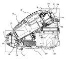
- FIG. 2 is a front view, a side view, and a cross-sectional view showing a cyclone type dust collecting portion that is a dust collecting case of the electric vacuum cleaner according to Embodiment 1 of the present invention.
- FIG. 3 is a central sectional view of the cleaner body according to Embodiment 1 of the present invention.
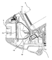
- FIG. 4 is an enlarged view of a portion A in FIG. FIG.
- FIG. 5 is a cross-sectional view showing the fitting between the cleaner body and the dust collecting case in FIG. 4.
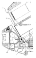
- FIG. 6 is an enlarged view of a portion B in FIG.
- FIG. 7 is a view for explaining an operation of releasing the engagement between the cleaner body and the dust collecting case in FIG. 6.
- a hose insertion port 2 at the front of the vacuum cleaner body 1 As shown in FIG. 1, in a vacuum cleaner 100, a hose insertion port 2 at the front of the vacuum cleaner body 1, a hose insertion part 4 at the end of a soft bellows hose 3, and a hose hand at the other end
- the state where the hose insertion part 4 of the extension hose part 6 having 5 is connected, the extension pipe 7 is connected to the hose proximal part 5 and the suction tool 8 is connected is the normal use state. Dust on the floor and the like is sucked together with air from the suction tool 8, and from the hose hand portion 5 of the extension pipe 7 and the extension hose portion 6 through the hose insertion portion 4 to the cleaner body 1 from the hose insertion port 2.
- Dust on the floor and the like is sucked together with air from the suction tool 8, and from the hose hand portion 5 of the extension pipe 7 and the extension hose portion 6 through the hose insertion portion 4 to the cleaner body 1 from the hose insertion
- the vacuum cleaner main body 1 communicates from the hose insertion port 2 via the main body intake port 2a, and has a dust collection chamber 10 in which a cyclone type dust collection part 9 as a dust collection case is accommodated, and a blower chamber 20.
- a suction fan motor 21 is provided in the blower chamber 20.
- the cyclone type dust collecting part 9 is detachably provided on the upper part of the cleaner body 1.
- the air containing dust sucked from the suction tool 8 passes through the extension pipe 7, the bellows hose 3, the hose insertion portion 4, the main body intake port 2 a, and the cylinder portion 2 b provided on the upper portion of the cleaner body 1, and the cyclone.
- the dust is sucked from the suction port 9a of the dust collector 9 and separated by the first centrifugal cylinder 11 and the second centrifugal cylinder 13 to accumulate the dust in the dust collecting case.
- FIG. 2A, 2B, and 2C are a front view, a side view, and a cross-sectional view, respectively, of the cyclone type dust collecting unit 9.
- FIG. The cyclone type dust collecting section 9 is disposed so as to be substantially parallel to the central axis A12 of the first centrifugal separation cylinder 11 and the central axis B14 of the second centrifugal separation cylinder 13, and collects the separated dust.
- a dust collection case 15 is provided in the dust collection case.
- the handle 16 is provided on the upper surface on the front side of the cyclone dust collector 9 and is shared by the cleaner body 1 and the cyclone dust collector 9. That is, as will be described later, when the dust collected in the dust collection chamber 10 in the cyclone type dust collecting unit 9 is discarded in the trash box, the cyclone type dust collecting unit 9 is detached from the cleaner body 1 and the handle 16 is held. The cyclone type dust collecting unit 9 is moved to above the trash box, and the dust accumulated in the dust collection chamber 15 in the dust collection case is discarded in the trash box. Moreover, the cleaner body 1 can be carried by holding the handle 16 while being locked to the cleaner body 1.
- the longitudinal direction of the cyclone type dust collecting part 9 is aligned with the direction along the central axis A12 and the central axis B14, and the valley 17 is formed by the outer diameter of the first centrifugal separation part 11 and the outer diameter of the second centrifugal separation part 13. Is used as a handle space under the handle. Therefore, the protrusion amount of the handle 16 from the cyclone type dust collecting portion 9 can be minimized, and the size of the cleaner body can be minimized.
- FIG. 3 is a central cross-sectional view of the vacuum cleaner main body 1 with the cyclone dust collecting unit 9 set therein.
- FIG. 4 is an enlarged view of a portion A in FIG. 3, that is, the vicinity of the locked portion A 18 and the locking portion B 19 that lock the cleaner body 1 and the front end of the cyclonic dust collector 9 described later.
- FIG. 5 is a cross-sectional view showing locking of the locked portion A18 and the locking portion B19.
- FIG. 6 is a cross-sectional view showing a portion B in FIG. 3, that is, the vicinity of the lock portion 30 that locks the vacuum cleaner main body 1 and the rear end of the cyclone dust collector 9 described later.
- FIG. 7 is a cross-sectional view for explaining the operation of releasing the locking of the lock portion 30.
- the cyclone type dust collecting unit 9 is removed from the cleaner body 1 so that the dust accumulated in the dust collecting chamber 15 in the dust collecting case is discarded and attached to the cleaner body 1 again.
- the locked portion A18 is fixed by being locked to the locking portion B19 on the cleaner body 1 side.
- the lower end of the locked portion A18 has a convex shape
- the locking portion B19 has a concave shape.
- the dimension of the locking part B19 is larger than the dimension of the convex part at the lower end of the locked part A18, and the cyclone type dust collecting part 9 can be slightly rotated in the direction in the drawing of FIG. 5 with the locking part B19 as a fulcrum. It has become.
- the other end side of the cyclone type dust collection part 9 is provided with the lock part 30 which is a locking mechanism, and the cyclone type dust collection part 9 is detachably fixed to the cleaner body 1.
- the lock portion 30 includes a lever 31, a latch 32, a latch locking portion 33, and a rotation cover 34.
- the lever 31 is provided on the cyclone type dust collecting unit 9 side, is supported so as to be slidable in an obliquely up and down direction, and is a release means for releasing the locking between the cleaner body 1 and the cyclone type dust collecting unit 9.
- the latch 32 is provided on the cyclone type dust collecting unit 9 side, and is rotatably supported in conjunction with the movement of the lever 31.
- the latch locking portion 33 is provided on the cleaner body 1 side and locked with the latch 32, whereby the cyclone dust collecting portion 9 is locked to the cleaner body 1.
- the rotation cover 34 is provided on the cyclone type dust collecting unit 9 side, is rotatably supported so as to cover the lever 31, and is a release prevention unit that prevents erroneous operation of the lever 31.
- the lever 31 In the lever 31, the upper surface 31 a of the lever 31 slides with the rear surface 35 a of the fixed cover 35, and the lower surface 31 b of the lower end of the lever 31 slides with the surface 22 on the cyclone dust collecting unit 9 side.
- the lever 31 has a wedge-shaped slope 31c at the lower end.
- the lever 31 is biased by the lever spring 37 in the lower right direction in FIG.
- the latch 32 is supported so as to be rotatable in the direction in the drawing of FIG.
- the latch 32 is biased counterclockwise by a latch spring 36.
- the upper end of the latch 32 has a wedge-shaped slope 32 a and faces the slope 31 c of the lever 31.
- the rotation cover 34 is rotatably provided so that the tip 34c covers the lever 31.
- the rotary cover 34 is pivotally supported around a rotary shaft 34a, and a rotary cover spring 34b, which is an elastic body such as a winding spring, is provided around the rotary shaft 34a.
- a rotary cover spring 34b which is an elastic body such as a winding spring, is provided around the rotary shaft 34a.
- One end of the rotary cover spring 34b is locked to the fixed cover 35 side, and the other end is locked to the rotary cover 34 side, and is biased in a direction covering the lever 31 (counterclockwise in the plane of FIG. 6).
- the latch 32 rotates in the direction opposite to the arrow E by the elastic force of the latch spring 36, and stops rotating when the inclined surface 31c of the lever 31 and the inclined surface 32a of the latch 32 come into contact with each other. That is, the rotation stops at the position where the lower end of the latch 32 is above the latch locking portion 33.
- the cyclone type dust collecting part 9 is separated from the cleaner body 1 in the state where the rear part of the cyclone type dust collecting part 9 is separated.
- the locked part A18 of the dust collecting part 9 is fitted into the locking part B19 of the cleaner body 1.
- the cyclone dust collector 9 is rotated clockwise, and the rear of the cyclone dust collector 9 is brought closer to the cleaner body 1.
- the inclined surface 32b of the latch 32 comes into contact with the inclined surface 33a of the latch locking portion 33, and the cyclone type dust collecting portion 9 is rotated in the clockwise direction, and the latch 32 is resisted against the elastic force of the latch spring 36.
- the latch 32 gets over the latch locking portion 33, the latch 32 rotates in the direction opposite to the arrow E by the elastic force of the latch spring 36, and the surface 33b of the latch 32 is in contact with the surface 33b of the latch locking portion 33. Abut. That is, the latch 32 is locked to the latch locking portion 33 in the state shown in FIG.
- the cyclone type dust collecting part 9 is latched to the cleaner body 1.
- the lever 31 can be covered with a simple structure, and erroneous operation of the lever 31 can be prevented. Further, since the rotating cover spring 34b that biases the rotating cover 34 in the closing direction is provided, the rotating cover 34 can cover the lever 31 after the operation of the lever 31, and the usability is improved. Further, since the rotary cover 34 covers the lever 31 in a normal state where the lever 31 is not operated, the lever 31 is not exposed and the design is improved. In particular, if the color of the rotary cover 34 and the surrounding cyclone type dust collecting portion 9 are the same, the rotary cover 34 is not conspicuous, and the design is further improved.
- the rotating cover 34 is made of a transparent material such as polyethylene resin or ABS resin, the user can easily see the position of the lever 31 and the usability is improved.
- the carrying of the vacuum cleaner main body 1 and the carrying of the cyclone type dust collecting unit 9 can be performed with the same handle 16, so that the size and weight can be reduced.
- the rotation cover 34 covers the lever 31 in a normal state, there is no fear that the lever 31 is erroneously operated when the cleaner body 1 is carried using the handle 16. For this reason, there is no worry that the cleaner body 1 falls, and it can be used safely.
- the lever 31 has been arranged in a place where there is no possibility of being released when the cleaner body 1 is carried in order to avoid an erroneous operation.
- the lever 31 can be operated only by opening the rotary cover 34, Since the lever 31 can be disposed at a convenient location, a vacuum cleaner with good design can be provided by hiding the lever.
- the vacuum cleaner main body having the dust collecting chamber and the air blowing chamber communicated with the main body inlet, the dust collecting case detachably accommodated in the dust collecting chamber, and the air blowing chamber
- a suction fan motor installed on the vacuum cleaner, a lock mechanism for locking the dust collection case to the cleaner body, and a dust collection case that is held in the state where the dust collection case is locked to the cleaner body.
- a handle Provided with a handle, a release means for releasing the locking mechanism, and a release prevention means provided to be openable and closable so as to cover the release means and to prevent the release means from being operated.
- the vacuum cleaner main body can be carried by holding the handle, and the vacuum cleaner main body can be prevented from falling off the dust collecting case and damaging the floor surface.
- the release preventing means is pivotally supported at one end side, the release means can be covered with a simple structure, and erroneous operation of the release means can be prevented.
- the release prevention means can cover the release means after the release means is operated, and the usability is improved. Moreover, since the release means is covered in a normal state where the release means is not operated, the release means is not exposed and the design is improved.
- the release prevention means is made of a transparent material, the user can easily see the position of the release means, and the usability is improved.
- FIG. 8 is a diagram for explaining the configuration of the closed state of the erroneous operation prevention cover of the electric vacuum cleaner according to Embodiment 2 of the present invention.
- FIG. 9 is a diagram illustrating the configuration of the opened state of the erroneous operation prevention cover of the electric vacuum cleaner according to Embodiment 2 of the present invention.
- the lock portion 30 includes a lever 31, a latch 32, a latch locking portion 33, and a slide cover 38.
- the slide cover cover 38 is provided on the cyclone type dust collecting unit 9 side, and is supported to be slidable so that the tip end portion 38 a covers the lever 31.
- the slide cover 38 is slidably provided between a cover holding part 39 provided integrally with the cyclone type dust collecting part 9 and a surface 35b of the fixed cover 35. That is, in the slide cover 38, the upper surface 38 b of the slide cover 38 is the back surface 39 a of the cover holding portion 39, the bottom surface 38 c of the slide cover 38 is the front surface 35 b of the fixed cover 35, and both side surfaces of the slide cover 38 are the cover holding portion 39. It slides on both side surfaces (not shown).
- the slide cover 38 is biased in the direction of arrow F by a slide cover spring 40 provided inside the cover holding portion 39.
- the latch 32 rotates in the direction opposite to the arrow E by the elastic force of the latch spring 36, and stops rotating when the inclined surface 31c of the lever 31 and the inclined surface 32a of the latch 32 come into contact with each other. That is, the rotation stops at the position where the lower end of the latch 32 is above the latch locking portion 33.
- the slide cover 38 since the slide cover 38 is slidably supported, the lever 31 can be covered with a simple structure, and erroneous operation of the lever 31 can be prevented. Further, the movement trajectory of the release prevention means at the time of opening and closing is smaller in the slide cover 38 than in the case where the release prevention means is constituted by the rotation cover 34, and is easy to use.
- the slide cover spring 40 that biases the slide cover 38 in the closing direction is provided, the slide cover 38 can cover the lever 31 after the operation of the lever 31, and the usability is improved. Further, since the slide cover 38 covers the lever 31 in a normal state where the lever 31 is not operated, the lever 31 is not exposed and the design is improved. In particular, if the colors of the slide cover 38 and the surrounding cyclone type dust collecting portion 9 are the same, the slide cover 38 is not conspicuous and the design is further improved.
- the slide cover 38 is made of a transparent material such as polyethylene resin or ABS resin, the user can easily see the position of the lever 31 and the usability is improved.
- the carrying of the cleaner main body 1 and the carrying of the cyclone type dust collecting unit 9 can be shared by the same handle 16, so that the size and weight can be reduced.
- the slide cover 38 covers the lever 31 in a normal state, there is no fear that the lever 31 is erroneously operated when the cleaner body 1 is carried using the handle 16. For this reason, there is no worry that the cleaner body 1 falls, and it can be used safely.
- the lever 31 has been arranged in a place where there is no fear of being released when the cleaner body 1 is carried in order to avoid an erroneous operation.
- the lever 31 can be operated only by opening the slide cover 38, Since the lever 31 can be disposed at a convenient location, a vacuum cleaner with good design can be provided by hiding the lever.
- the vacuum cleaner main body having the dust collection chamber and the blower chamber communicating with the main body inlet, the dust collection case detachably accommodated in the dust collection chamber, and the blower chamber
- a suction fan motor installed on the vacuum cleaner, a lock mechanism for locking the dust collection case to the cleaner body, and a dust collection case that is held in the state where the dust collection case is locked to the cleaner body.
- a handle Provided with a handle, a release means for releasing the locking mechanism, and a release prevention means provided to be openable and closable so as to cover the release means and to prevent the release means from being operated.
- the vacuum cleaner main body can be carried by holding the handle, and the vacuum cleaner main body can be prevented from falling off the dust collecting case and damaging the floor surface.
- the release preventing means is slidably supported, the release means can be covered with a simple structure, and erroneous operation of the release means can be prevented.
- the release prevention means can cover the release means after the release means is operated, and the usability is improved. Moreover, since the release means is covered in a normal state where the release means is not operated, the release means is not exposed and the design is improved.
- the release prevention means is made of a transparent material, the user can easily see the position of the release means, and the usability is improved.
- Embodiment 3 In the first embodiment, a rotating cover pivotally supported at one end side is used as a release preventing means.
- a rotating cover pivotally supported at one end side is used as a release preventing means.
- the rotating cover in addition to the configuration of the first embodiment, when the rotating cover is opened.
- the rotating cover is temporarily fixed at the opened position to maintain the opened state, and the temporarily fixed state of the rotating cover is released when the lever is operated.
- Other configurations are the same as those of the first embodiment, and the same components are denoted by the same reference numerals and detailed description thereof is omitted.
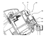
- FIG. 10 is a diagram for explaining the configuration of the rotary cover of the vacuum cleaner in the third embodiment of the present invention in the open state (when temporarily fixed).
- 11 is a cross-sectional view of the lock portion in FIG.
- FIG. 12 is a cross-sectional view for explaining the operation of operating the lever in FIG. 11 to release the temporarily fixed state of the rotary cover.
- 6 has the same configuration as the third embodiment of the present invention shown in FIG. 6 except for a slide-type release button cover 22 which is a mechanism for sliding and opening the release button cover 19 supported by the spring 21. Therefore, the same components are denoted by the same reference numerals, and detailed description thereof is omitted.
- FIG. 10 is a side sectional view showing a state in which the slide type release button cover 21 is opened.
- a temporary fixing piece 41a is provided on one side surface of the rotation cover 41 which is a release preventing means.
- the temporary fixing piece 41 a is provided with notches 41 c on both sides thereof, and a claw portion 41 b that protrudes inward of the rotary cover 41 is provided at the tip portion.
- the claw portion 41b can be elastically deformed in a direction orthogonal to the side surface of the rotary cover 41 on which the temporary fixing piece 41a is provided by the notch 41c.
- a locked portion to which the claw portion 41b is locked is provided at the lower end of the latch 43.
- the rotation cover 41 is maintained in the opened state when the rotation cover 41 is opened, the operator inserts a finger into the gap between the lever 31 and the rotation cover 41. It becomes easy and usability improves. Further, since the release preventing means is unlocked when the lever 31 is operated, it is not necessary for the operator to perform the operation of closing the rotary cover 41, and the usability is improved.
- the electric vacuum cleaner 100 of the third embodiment since the carrying of the vacuum cleaner main body 1 and the carrying of the cyclone type dust collecting unit 9 can be shared by the same handle 16, it can be reduced in size and weight.
- the rotation cover 41 since the rotation cover 41 is maintained in a state of covering the upper side of the lever 31, there is no fear that the lever 31 is erroneously operated when the cleaner body 1 is carried using the handle 16. For this reason, there is no worry that the cleaner body 1 falls, and it can be used safely.
- the lever 31 has been arranged in a place where there is no possibility of being released when the cleaner body 1 is carried in order to avoid an erroneous operation.
- the lever 31 can be operated only by opening the rotary cover 34, Since the lever 31 can be disposed at a convenient location, a vacuum cleaner with good design can be provided by hiding the lever.
- the vacuum cleaner main body having the dust collection chamber and the blower chamber communicating with the main body intake port, the dust collection case detachably accommodated in the dust collection chamber, and the blower chamber
- a suction fan motor installed on the vacuum cleaner, a lock mechanism for locking the dust collection case to the cleaner body, and a dust collection case that is held in the state where the dust collection case is locked to the cleaner body.
- a handle a handle for releasing the locking mechanism, and a release prevention means provided to be openable and closable so as to cover the release means and to prevent the release means from being operated.
- the cleaner body can be carried by holding the handle, and the cleaner body can be prevented from falling off the dust collecting case and damaging the floor surface.
- the release preventing means is pivotally supported at one end side, the release means can be covered with a simple structure, and erroneous operation of the release means can be prevented.
- the release prevention means can cover the release means after the release means is operated, and the usability is improved. Moreover, since the release means is covered in a normal state where the release means is not operated, the release means is not exposed and the design is improved.
- the release prevention means is made of a transparent material, the user can easily see the position of the release means, and the usability is improved.
- the release preventing means is configured to be locked at the time of opening and the release preventing means is released when the release means is operated so as to release the lock of the lock mechanism, the usability is improved.
- Vacuum cleaner body 2 hose insertion port, 2a body intake port, 2b cylinder part, 3 bellows hose, 4 hose insertion part, 5 hose hand part, 6 extension hose part, 7 extension pipe, 8 suction tool, 9 cyclone Type dust collecting part (dust collecting case), 9a suction port, 10 dust collecting chamber, 11 first centrifuge cylinder, 12 central axis A, 13 second centrifuge cylinder, 14 central axis B, 15 inside dust collecting case Dust collection chamber, 16 handle, 17 valley, 18 locked part A, 19 locking part B, 20 air blowing chamber, 21 suction fan motor, 22 faces, 30 lock part (lock mechanism), 31 lever (release means), 31a upper surface, 31b lower surface, 31c slope, 32 latch, 32a slope, 32b slope, 32c face, 33 latch locking part, 33a slope, 33b face, 34 rotating cover (release Stopping means), 34a rotating shaft, 34b rotating cover spring (elastic body), 34c tip, 35 fixed cover, 35a back surface, 35b front surface, 36
Landscapes
- Engineering & Computer Science (AREA)
- Mechanical Engineering (AREA)
- Filters For Electric Vacuum Cleaners (AREA)
- Electric Vacuum Cleaner (AREA)
Abstract
掃除機本体に係止された集塵ケースのハンドルを持って掃除機本体を持ち運ぶときに、集塵ケースと掃除機本体との係止を解除するロック解除ボタンが誤って操作されることを防止する、安全で使い勝手のよい電気掃除機を提供する。本体吸気口(2a)に連通した集塵室(10)と送風室(20)を有する掃除機本体(1)と、集塵室(10)に着脱自在に収容される集塵ケース(9)と、送風室(20)内に設置される吸引ファンモータ(21)と、集塵ケース(9)を掃除機本体(1)に係止するロック機構(30)と、集塵ケース(9)に設けられるとともに集塵ケース(9)が掃除機本体(1)に係止された状態で把持されるハンドル(16)と、ロック機構(30)の係止を解除する解除手段(31)と、解除手段(31)を覆うように開閉自在に設けられると共に解除手段(31)の操作を防止する解除防止手段(34)とを備えた。
Description
本発明は、掃除機本体に着脱自在の集塵ケースにハンドルを有する電気掃除機に関するものである。
従来の電気掃除機は、掃除機本体に着脱自在な集塵ケースを設けているものがある。集塵方式としてはサイクロン式や紙パック式が広く用いられている。いずれの方式においても、集塵ケースを掃除機本体から取り外してゴミ捨てを行なうのが一般的である。
集塵ケースを掃除機本体から取り外してゴミ捨てを行うために、集塵ケースに持ち運び用のハンドルや取っ手が設けられる。なお、掃除機本体を持ち運ぶ際、掃除機本体側に持ち運び用のハンドルや取っ手を設けてもよい。しかし、集塵ケースに設けたハンドルや取っ手を把持して、集塵ケースが掃除機本体に装着された状態で掃除機本体の持ち運びを行うことにより、掃除機本体に設けるハンドルや取っ手を無くせば、掃除機本体が小型化でき、使用者にとって使いやすいものとなる。
集塵ケースが掃除機本体に装着された状態で、集塵ケースのハンドルや取っ手を把持して掃除機本体を持ち運ぶときに、集塵ケースから掃除機本体が外れて落下しないように、集塵ケースを掃除機本体に固定するロック機構が設けられる。しかし、ロック機構の係止を解除するロック解除ボタンが誤って押されてしまうと、掃除機本体が集塵ケースから外れて落下し、床にキズをつけてしまう虞があった。これに対し、ロック解除ボタンの位置をロック機構の設けられる位置から離れた位置に設け、ロック解除ボタンを誤って操作しにくくすることが考えられるが、使い勝手が悪いという課題がある。そこで、ロック解除ボタンをロック機構に近接して配置するとともに、集塵ケースの取っ手を把持して掃除機本体を持ち上げたときに、集塵ケースとロック解除ボタンが掃除機本体に対し相対的にわずかに上方へ移動し、ロック解除ボタンの後面が掃除機本体側と干渉することにより、集塵ケースと掃除機本体とのロック解除ボタンを押せない構造としているものがある(例えば、特許文献1参照)。
しかしながら上記の従来の構造では、ロック解除時に取っ手を把持すると、取っ手が上方向に移動する方向に力が働いてしまいやすい構造となっているため、取っ手が上方向に移動するとロック解除ボタンを操作できず、使い勝手が悪いという課題があった。
本発明は、前述のような課題を解決するためになされたものであり、集塵ケースに設けたハンドルを把持して掃除機本体も持ち運びできるとともに、掃除機本体を持ち運ぶときに、集塵ケースと掃除機本体との係止を解除するロック解除ボタンが誤って操作されることを防止する、安全で使い勝手のよい電気掃除機を提供することを目的とする。
本発明の電気掃除機は、本体吸気口に連通した集塵室と送風室を有する掃除機本体と、集塵室に着脱自在に収容される集塵ケースと、送風室内に設置される吸引ファンモータと、集塵ケースを掃除機本体に係止するロック機構と、集塵ケースに設けられるとともに集塵ケースが掃除機本体に係止された状態で把持されるハンドルと、ロック機構の係止を解除する解除手段と、解除手段を覆うように開閉自在に設けられると共に解除手段の操作を防止する解除防止手段とを備えたものである。
本発明によれば、集塵ケースに設けたハンドルを把持して掃除機本体も持ち運びできるとともに、掃除機本体が集塵ケースから外れて落下し床面を傷つけることを防止できる。
実施の形態1.
集塵方式としてサイクロン式集塵方式を例にとり説明する。本発明は、サイクロン式集塵方式にかぎらず、紙パック集塵方式の場合にも適用できる。
図1は、本発明の実施の形態1に係る電気掃除機の外観を示す斜視図である。図2は、本発明の実施の形態1に係る電気掃除機の集塵ケースであるサイクロン式集塵部を示す正面図、側面図および断面図である。図3は、本発明の実施の形態1に係る掃除機本体の中央断面図である。図4は、図3のA部拡大図である。図5は、図4における掃除機本体と集塵ケースとの嵌合を示す断面図である。図6は、図3のB部拡大図である。図7は、図6における掃除機本体と集塵ケースとの係止を解除する動作を説明する図である。
集塵方式としてサイクロン式集塵方式を例にとり説明する。本発明は、サイクロン式集塵方式にかぎらず、紙パック集塵方式の場合にも適用できる。
図1は、本発明の実施の形態1に係る電気掃除機の外観を示す斜視図である。図2は、本発明の実施の形態1に係る電気掃除機の集塵ケースであるサイクロン式集塵部を示す正面図、側面図および断面図である。図3は、本発明の実施の形態1に係る掃除機本体の中央断面図である。図4は、図3のA部拡大図である。図5は、図4における掃除機本体と集塵ケースとの嵌合を示す断面図である。図6は、図3のB部拡大図である。図7は、図6における掃除機本体と集塵ケースとの係止を解除する動作を説明する図である。
図1に示すように、電気掃除機100において、掃除機本体1の前部にあるホース差込口2に、軟質の蛇腹ホース3の端部にホース差込部4と他端にホース手元部5を持つ延長ホース部6のホース差込部4を接続し、前記ホース手元部5に延長パイプ7を接続し、さらに吸込具8を接続した状態が通常使用状態である。床面等の塵埃は空気と共に吸込具8から吸引され、延長パイプ7、延長ホース部6のホース手元部5からホース差込部4を経由してホース差込口2より掃除機本体1へと導かれる。
掃除機本体1は、ホース差込口2から本体吸気口2aを経由して連通し、集塵ケースであるサイクロン式集塵部9が収容される集塵室10と、送風室20を有する。送風室20内には吸引ファンモータ21が設けられる。
サイクロン式集塵部9は掃除機本体1の上部に着脱自在に設けられる。吸込具8から吸引された塵埃を含む空気は、延長パイプ7、蛇腹ホース3、ホース差込部4、本体吸気口2aから掃除機本体1の上部に設けられた筒部2bを通って、サイクロン式集塵部9の吸引口9aより吸引し、第一の遠心分離筒11と第二の遠心分離筒13で分離して塵埃を集塵ケース内に蓄積する。
図2(a)、(b)及び(c)は、それぞれ、サイクロン式集塵部9の正面図、側面図及び断面図である。サイクロン式集塵部9は、第一の遠心分離筒11の中心軸A12及び第二の遠心分離筒13の中心軸B14と略平行になるように配置されており、分離した塵埃を溜めるための集塵ケース内集塵室15を備えている。
ハンドル16は、サイクロン式集塵部9の前面側上面に設けられ、掃除機本体1及びサイクロン式集塵部9の持ち運び共用である。すなわち、後述するように、サイクロン式集塵部9内の集塵室10に溜まった塵埃をゴミ箱に廃棄する場合、サイクロン式集塵部9を掃除機本体1から取り外し、ハンドル16を把持してサイクロン式集塵部9をゴミ箱の上方まで移動し、集塵ケース内集塵室15に溜まった塵埃をゴミ箱に廃棄する。また、掃除機本体1に係止された状態でハンドル16を把持することにより、掃除機本体1を持ち運びできる。
サイクロン式集塵部9の長手方向を中心軸A12及び中心軸B14と沿う方向にそろえ、第一の遠心分離部11の外径と第二の遠心分離部13の外径とで作られる谷間17をハンドル下部の手かけスペースとして利用している。そのため、ハンドル16のサイクロン式集塵部9からの突出量を最低限に抑えることが出来て、掃除機本体のサイズも最小限で抑えられる。
図3は掃除機本体1にサイクロン式集塵部9がセットされた状態の中央断面図である。図4は、図3のA部、すなわち、後述する掃除機本体1とサイクロン式集塵部9の前端とを係止する被係止部A18と係止部B19近傍の拡大図である。図5は被係止部A18と係止部B19の係止を示す断面図である。図6は、図3におけるB部、すなわち、後述する掃除機本体1とサイクロン式集塵部9の後端とを係止するロック部30の近傍を示す断面図である。図7はロック部30の係止を解除する動作を説明する断面図である。
サイクロン式集塵部9は、掃除機本体1より取り外して集塵ケース内集塵室15に溜まった塵埃を捨て、再び掃除機本体1に取付けられるように、サイクロン式集塵部9の一端の被係止部A18が掃除機本体1側の係止部B19に係止されることにより固定される。ここで、図5に示すように、被係止部A18の下端は凸状の形状をなし、係止部B19は凹状の形状をなす。係止部B19の寸法は被係止部A18の下端の凸部の寸法より大きく、サイクロン式集塵部9は係止部B19を支点として、図5の紙面内の方向に若干回動可能となっている。また、サイクロン式集塵部9の他端側には、ロック機構であるロック部30を備え、サイクロン式集塵部9が掃除機本体1と着脱自在で固定される構造となっている。
図6に示すように、ロック部30は、レバー31と、ラッチ32と、ラッチ係止部33と、回転カバー34とから構成される。レバー31は、サイクロン式集塵部9側に設けられ、斜め上下方向に摺動自在に支持され、掃除機本体1とサイクロン式集塵部9との係止を解除する解除手段である。ラッチ32は、サイクロン式集塵部9側に設けられ、レバー31の動きに連動して回動自在に支持される。ラッチ係止部33は、掃除機本体1側に設けられ、ラッチ32と係止されることにより、サイクロン式集塵部9が掃除機本体1に係止される。回転カバー34は、サイクロン式集塵部9側に設けられ、レバー31を覆うように回動自在に支持され、レバー31の誤操作を防止する解除防止手段である。
レバー31は、レバー31の上面31aが固定カバー35の裏面35aと摺動し、レバー31の下端の下面31bがサイクロン式集塵部9側の面22と摺動する。レバー31の下端には楔状の斜面31cを有する。レバー31は、レバー用バネ37により図6の右下方向に付勢される。
ラッチ32は、図6の紙面内の方向に回動自在に支持される。ラッチ32は、ラッチ用バネ36により反時計方向に付勢される。ラッチ32の上端には楔形状の斜面32aを有し、レバー31の斜面31cと対向する。
回転カバー34は、先端部34cがレバー31を覆うように回動自在に設けられる。回転カバー34は回転軸34aの周りに枢支され、回転軸34aの周りに、例えば巻きバネのような弾性体である回転カバー用バネ34bが設けられる。回転カバー用バネ34bの一端は固定カバー35側に係止され、他端は回転カバー34側に係止され、レバー31を覆う方向(図6の紙面において反時計方向)に付勢される。
次に、サイクロン集塵部9と掃除機本体1との着脱の動作について説明する。
サイクロン集塵部9が掃除機本体1に装着された状態において、サイクロン式集塵部9の前方では、サイクロン式集塵部9側に設けられた被係止部A18が掃除機本体1側に設けられた係止部B19と係止される。一方、サイクロン式集塵部9の後方のロック部30においては、フック32がラッチ係止部33に係止される。このとき、ロック部30の係止を解除するレバー31の上方は回転カバー34に覆われているため、使用者の指をレバー31に掛けて操作することができない。このように、使用者がハンドル16を把持して掃除機本体1を運搬中に誤ってレバー31を操作することができないので、掃除機本体1がサイクロン式集塵部9から外れて床面を傷つけることを防止できる。
サイクロン集塵部9が掃除機本体1に装着された状態において、サイクロン式集塵部9の前方では、サイクロン式集塵部9側に設けられた被係止部A18が掃除機本体1側に設けられた係止部B19と係止される。一方、サイクロン式集塵部9の後方のロック部30においては、フック32がラッチ係止部33に係止される。このとき、ロック部30の係止を解除するレバー31の上方は回転カバー34に覆われているため、使用者の指をレバー31に掛けて操作することができない。このように、使用者がハンドル16を把持して掃除機本体1を運搬中に誤ってレバー31を操作することができないので、掃除機本体1がサイクロン式集塵部9から外れて床面を傷つけることを防止できる。
次に、ゴミを捨てるために、サイクロン集塵部9を掃除機本体1から取り外す場合は、図7に示すように、操作者は一方の手でサイクロン式集塵部9のハンドル16を把持し、回転カバー34の先端部34cに他方の手の指を掛け、回転カバー34を、回転カバー用バネ34bの弾性力に抗して矢印Cの方向に回転する。すると、レバー31と回転カバー34との間に隙間が生じるので、ここに指を挿入することができる。
レバー31と回転カバー34との隙間に挿入した指をレバー31に掛け、レバー31をレバー用バネ37の弾性力に抗して矢印Dの方向に移動する。レバー31の移動に伴ってレバー31の斜面31cがラッチ32の斜面32aを押し上げ、ラッチ32はラッチ用バネ36の弾性力に抗して矢印Eの方向に回転する。ラッチ32が回転すると、ラッチ係止部33とラッチ32との係止が解除される。すなわち、サイクロン式集塵部9のロック部30の係止が解除される。
サイクロン式集塵部9のロック部30の係止が解除された状態で、サイクロン式集塵部9を矢印Dの方向に移動すると、サイクロン式集塵部9が係止部B19を支点として回転する(図4参照)。そして、ラッチ32の下端がラッチ係止部33の上端を越える位置まで回転したところで、レバー31に掛けた指の力を抜くと、レバー31はレバー用バネ37の弾性力により矢印Dと反対の方向に移動して最初の位置に戻る。レバー31の移動によりレバー31の斜面31cがラッチ32の斜面32aの下方に移動する。これに伴ってラッチ32はラッチ用バネ36の弾性力により矢印Eと逆方向に回転し、レバー31の斜面31cとラッチ32の斜面32aとが当接する状態となったところで回転が停止する。すなわち、ラッチ32の下端がラッチ係止部33の上方の位置で回転が停止することになる。
レバー31が最初の位置に戻ったところで、指をレバー31と回転カバー34との隙間から引き抜く。すると、回転カバー34は回転カバー用バネ34bの弾性力により矢印Cと反対の方向に回転し、回転カバー34がレバー31を覆う最初の位置に戻る。
ラッチ32の下端がラッチ係止部33の上端を越える位置まで回転したところで、サイクロン式集塵部9を斜め後方(図7の右上方向)に引き抜くことにより、サイクロン式集塵部9の被係止部A18と掃除機本体1の係止部B19との係止が解除され、サイクロン式集塵部9を掃除機本体1から取り外すことができる。
最後に、サイクロン式集塵部9を掃除機本体1に装着する場合は、図5に示すように、まず、サイクロン式集塵部9の後部を掃除機本体1から離間した状態で、サイクロン式集塵部9の被係止部A18を掃除機本体1の係止部B19に嵌めこむ。
次に、係止部B19を支点として、サイクロン式集塵部9を時計方向に回転して、サイクロン式集塵部9の後方を掃除機本体1に近づける。このとき、まず、ラッチ32の斜面32bがラッチ係止部33の斜面33aと当たり、サイクロン式集塵部9が時計方向に回転されるとともに、ラッチ用バネ36の弾性力に抗してラッチ32が矢印Eの方向に回転する。そして、ラッチ32がラッチ係止部33を乗り越えると、ラッチ32はラッチ用バネ36の弾性力により矢印Eと反対の方向に回転し、ラッチ32の面33bがラッチ係止部33の面33bと当接する。つまり、図6に示す状態で、ラッチ32がラッチ係止部33に係止される。このように、サイクロン式集塵部9が掃除機本体1に係止される。
このように、回転カバー34は、一端側が回動自在に枢支されるので、簡単な構造でレバー31を覆うことができ、レバー31の誤操作を防止することができる。また、回転カバー34を閉じる方向に付勢する回転カバー用バネ34bを備えたので、レバー31の操作を行ったあとは回転カバー34がレバー31を覆うことができ、使い勝手がよくなる。また、レバー31を操作しない通常の状態で回転カバー34がレバー31を覆うので、レバー31が露出せず、デザイン性が向上する。特に、回転カバー34とその周囲のサイクロン式集塵部9の色を同じにすれば、回転カバー34が目立たず、デザイン性が一層向上する。
また、回転カバー34を透明な素材であるポリエチレン樹脂やABS樹脂等で構成すれば、使用者はレバー31の位置を容易に視認でき、使い勝手がよくなる。
以上のように、実施の形態1における電気掃除機100によれば、掃除機本体1の持ち運びとサイクロン式集塵部9の持ち運びが同じハンドル16で兼用できるので、小型化、軽量化できる。また、通常の状態で回転カバー34がレバー31を覆うので、ハンドル16を用いて掃除機本体1を持ち運ぶ時に、誤ってレバー31が操作されてしまう心配がない。このため、掃除機本体1が落下する心配が無く安全に使用することができる。また、従来、誤操作などを避けるためにレバー31を掃除機本体1持ち運び時に解除されてしまう恐れのない場所に配置していたが、回転カバー34を開動させるだけでレバー31を操作でき、使用者の使い勝手の良い場所にレバー31を配置することが出来るので、レバーを隠すことによりデザイン性も良い電気掃除機を提供することができる。
このように、実施の形態1の電気掃除機では、本体吸気口に連通した集塵室と送風室を有する掃除機本体と、集塵室に着脱自在に収容される集塵ケースと、送風室内に設置される吸引ファンモータと、集塵ケースを前記掃除機本体に係止するロック機構と、集塵ケースに設けられるとともに前記集塵ケースが前記掃除機本体に係止された状態で把持されるハンドルと、ロック機構の係止を解除する解除手段と、解除手段を覆うように開閉自在に設けられると共に前記解除手段の操作を防止する解除防止手段とを備えたので、集塵ケースに設けたハンドルを把持して掃除機本体も持ち運びできるとともに、掃除機本体が集塵ケースから外れて落下し床面を傷つけることを防止できる。
また、解除防止手段は、一端側が回動自在に枢支されるので、簡単な構造で解除手段を覆うことができ、解除手段の誤操作を防止することができる。
また、解除防止手段を閉じる方向に付勢する弾性体を備えたので、解除手段の操作を行ったあとは解除防止手段が解除手段を覆うことができ、使い勝手がよくなる。また、解除手段を操作しない通常の状態で解除手段を覆うので、解除手段が露出せず、デザイン性が向上する。
また、解除防止手段を透明な素材で構成したので、使用者は解除手段の位置を容易に視認でき、使い勝手がよくなる。
実施の形態2.
解除防止手段として実施の形態1では一端側が回動自在に枢支された回転カバーを用いたが、実施の形態2では摺動自在に支持されたスライドカバーとするものである。その他の構成は実施の形態1と同様であり、同一の構成については同一の符号を付して詳細な説明は省略する。
図8は、本発明の実施の形態2に係る電気掃除機の誤操作防止カバーの閉成状態の構成を説明する図である。図9は、本発明の実施の形態2に係る電気掃除機の誤操作防止カバーの開成状態の構成を説明する図である。
解除防止手段として実施の形態1では一端側が回動自在に枢支された回転カバーを用いたが、実施の形態2では摺動自在に支持されたスライドカバーとするものである。その他の構成は実施の形態1と同様であり、同一の構成については同一の符号を付して詳細な説明は省略する。
図8は、本発明の実施の形態2に係る電気掃除機の誤操作防止カバーの閉成状態の構成を説明する図である。図9は、本発明の実施の形態2に係る電気掃除機の誤操作防止カバーの開成状態の構成を説明する図である。
図8に示すように、ロック部30は、レバー31と、ラッチ32と、ラッチ係止部33と、スライドカバー38とから構成される。スライドカバーカバー38はサイクロン式集塵部9側に設けられ、先端部38aがレバー31を覆うように摺動自在に支持され、レバー31の誤操作を防止する解除防止手段である。
スライドカバー38は、サイクロン式集塵部9に一体的に設けられたカバー保持部39と固定カバー35の表面35bとの間に摺動自在に設けられる。すなわち、スライドカバー38は、スライドカバー38の上面38bがカバー保持部39の裏面39aと、スライドカバー38の底面38cが固定カバー35の表面35bと、スライドカバー38の両側面がカバー保持部39の内部の両側面と摺動する(図示せず)。スライドカバー38は、カバー保持部39の内部に設けられたスライドカバー用バネ40により、矢印Fの方向に付勢される。
次に、サイクロン集塵部9と掃除機本体1との着脱の動作について説明する。
ゴミを捨てるために、サイクロン集塵部9を掃除機本体1から取り外す場合は、図8に示すように、操作者は一方の手でサイクロン式集塵部9のハンドル16を把持し、スライドカバー38の先端部38aに他方の手の指を掛け、スライドカバー38を、スライドカバー用バネ40の弾性力に抗して矢印Fと反対の方向に移動する。すると、レバー31とスライドカバー38との間に隙間が生じるので、ここに指を挿入することができる(図9参照)。
ゴミを捨てるために、サイクロン集塵部9を掃除機本体1から取り外す場合は、図8に示すように、操作者は一方の手でサイクロン式集塵部9のハンドル16を把持し、スライドカバー38の先端部38aに他方の手の指を掛け、スライドカバー38を、スライドカバー用バネ40の弾性力に抗して矢印Fと反対の方向に移動する。すると、レバー31とスライドカバー38との間に隙間が生じるので、ここに指を挿入することができる(図9参照)。
レバー31とスライドカバー38との隙間に挿入した指をレバー31に掛け、レバー31をレバー用バネ37の弾性力に抗して矢印Dの方向に移動する。図7に示すように、レバー31の移動に伴ってレバー31の斜面31cがラッチ32の斜面32aを押し上げ、ラッチ32はラッチ用バネ36の弾性力に抗して矢印Eの方向に回転する。ラッチ32が回転すると、ラッチ係止部33とラッチ32との係止が解除される。すなわち、サイクロン式集塵部9のロック部30の係止が解除される。
サイクロン式集塵部9のロック部30の係止が解除された状態で、サイクロン式集塵部9を矢印Dの方向に移動すると、サイクロン式集塵部9が係止部B19を支点として回転する(図4参照)。そして、ラッチ32の下端がラッチ係止部33の上端を越える位置まで回転したところで、レバー31に掛けた指の力を抜くと、レバー31はレバー用バネ37の弾性力により矢印Dと反対の方向に移動して最初の位置に戻る。レバー31の移動によりレバー31の斜面31cがラッチ32の斜面32aの下方に移動する。これに伴ってラッチ32はラッチ用バネ36の弾性力により矢印Eと逆方向に回転し、レバー31の斜面31cとラッチ32の斜面32aとが当接する状態となったところで回転が停止する。すなわち、ラッチ32の下端がラッチ係止部33の上方の位置で回転が停止することになる。
レバー31が最初の位置に戻ったところで、指をレバー31とスライドカバー38との隙間から引き抜く。すると、スライドカバー38はスライドカバー用バネ40の弾性力により矢印Fの方向に移動し、スライドカバー38がレバー31を覆う最初の位置に戻る。
ラッチ32の下端がラッチ係止部33の上端を越える位置まで回転したところで、サイクロン式集塵部9を斜め後方(図7の右上方向)に引き抜くことにより、サイクロン式集塵部9の被係止部A18と掃除機本体1の係止部B19との係止が解除され、サイクロン式集塵部9を掃除機本体1から取り外すことができる。
最後に、サイクロン式集塵部9を掃除機本体1に装着する場合については、実施の形態1に記載した動作と同じである。
このように、スライドカバー38は、摺動自在に枢支されるので、簡単な構造でレバー31を覆うことができ、レバー31の誤操作を防止することができる。また、開閉時の解除防止手段の移動軌跡は、解除防止手段を回転カバー34で構成した場合と比較し、スライドカバー38の方が小さく、使い勝手がよい。また、スライドカバー38を閉じる方向に付勢するスライドカバー用バネ40を備えたので、レバー31の操作を行ったあとはスライドカバー38がレバー31を覆うことができ、使い勝手がよくなる。また、レバー31を操作しない通常の状態でスライドカバー38がレバー31を覆うので、レバー31が露出せず、デザイン性が向上する。特に、スライドカバー38とその周囲のサイクロン式集塵部9の色を同じにすれば、スライドカバー38が目立たず、デザイン性が一層向上する。
また、スライドカバー38を透明な素材であるポリエチレン樹脂やABS樹脂等で構成すれば、使用者はレバー31の位置を容易に視認でき、使い勝手がよくなる。
以上のように、実施の形態2における電気掃除機100によれば、掃除機本体1の持ち運びとサイクロン式集塵部9の持ち運びが同じハンドル16で兼用できるので、小型化、軽量化できる。また、通常の状態でスライドカバー38がレバー31を覆うので、ハンドル16を用いて掃除機本体1を持ち運ぶ時に誤ってレバー31が操作されてしまう心配がない。このため、掃除機本体1が落下する心配が無く安全に使用することができる。また、従来、誤操作などを避けるためにレバー31を掃除機本体1持ち運び時に解除されてしまう恐れのない場所に配置していたが、スライドカバー38を開動させるだけでレバー31を操作でき、使用者の使い勝手の良い場所にレバー31を配置することが出来るので、レバーを隠すことによりデザイン性も良い電気掃除機を提供することができる。
このように、実施の形態2の電気掃除機では、本体吸気口に連通した集塵室と送風室を有する掃除機本体と、集塵室に着脱自在に収容される集塵ケースと、送風室内に設置される吸引ファンモータと、集塵ケースを前記掃除機本体に係止するロック機構と、集塵ケースに設けられるとともに前記集塵ケースが前記掃除機本体に係止された状態で把持されるハンドルと、ロック機構の係止を解除する解除手段と、解除手段を覆うように開閉自在に設けられると共に前記解除手段の操作を防止する解除防止手段とを備えたので、集塵ケースに設けたハンドルを把持して掃除機本体も持ち運びできるとともに、掃除機本体が集塵ケースから外れて落下し床面を傷つけることを防止できる。
また、解除防止手段は、摺動自在に支持されるので、簡単な構造で解除手段を覆うことができ、解除手段の誤操作を防止することができる。
また、解除防止手段を閉じる方向に付勢する弾性体を備えたので、解除手段の操作を行ったあとは解除防止手段が解除手段を覆うことができ、使い勝手がよくなる。また、解除手段を操作しない通常の状態で解除手段を覆うので、解除手段が露出せず、デザイン性が向上する。
また、解除防止手段を透明な素材で構成したので、使用者は解除手段の位置を容易に視認でき、使い勝手がよくなる。
実施の形態3.
解除防止手段として実施の形態1では一端側が回動自在に枢支された回転カバーを用いたが、実施の形態3の電気掃除機では、実施の形態1の構成に加え、回転カバーの開成時に回転カバーが開成位置で仮固定され、開成状態を維持するとともに、レバーを操作したときに回転カバーの仮固定状態が解除されるものである。その他の構成は実施の形態1と同様であり、同一の構成については同一の符号を付して詳細な説明は省略する。
解除防止手段として実施の形態1では一端側が回動自在に枢支された回転カバーを用いたが、実施の形態3の電気掃除機では、実施の形態1の構成に加え、回転カバーの開成時に回転カバーが開成位置で仮固定され、開成状態を維持するとともに、レバーを操作したときに回転カバーの仮固定状態が解除されるものである。その他の構成は実施の形態1と同様であり、同一の構成については同一の符号を付して詳細な説明は省略する。
図10は、本発明の第3の実施の形態における電気掃除機の回転カバーの開成状態(仮固定時)の構成を説明する図である。図11は、図10におけるロック部の横断面図である。図12は、図11においてレバーを操作して回転カバーの仮固定状態が解除される動作を説明する横断面図である。なお、図6に示した本発明の第3の実施の形態と、バネ21に支持された解除ボタンカバー19をスライドして開動させる機構としたスライド式解除ボタンカバー22以外は同様の構成を有するものであり、同一の構成については同一の符号を付して詳細な説明は省略する。また、図10はスライド式解除ボタンカバー21を開動させた状態の側断面図である。
図10に示すように、解除防止手段である回転カバー41の一方の側面に仮固定片41aが設けられる。仮固定片41aはその両側に切欠41cが設けられ、先端部に回転カバー41の内側方向に突出した爪部41bが設けられる。爪部41bは、切欠41cにより、仮固定片41aが設けられる回転カバー41の側面に対し直交する方向に弾性変形が可能となっている。ラッチ43の下端には、爪部41bが係止される被係止部が設けられる。
次に、回転カバーの動作について説明する。
図10に示すように、回転カバー41を開成すると、回転カバー41の回転移動に連動して爪部41bが回転移動する。ラッチ43下端の被係止部43aに係止されるまでは、爪部41bは回転カバー41の外側方向に弾性変形して、ラッチ43の側面に乗り上げて摺動し、被係止部43aの位置でラッチ43の下端に嵌るように係止される。この状態で回転カバー41の開成状態が維持される。
図10に示すように、回転カバー41を開成すると、回転カバー41の回転移動に連動して爪部41bが回転移動する。ラッチ43下端の被係止部43aに係止されるまでは、爪部41bは回転カバー41の外側方向に弾性変形して、ラッチ43の側面に乗り上げて摺動し、被係止部43aの位置でラッチ43の下端に嵌るように係止される。この状態で回転カバー41の開成状態が維持される。
次に、レバー31を図7の矢印Dの方向に移動すると、レバー31の移動に連動してラッチ32が上方に移動し、ラッチ32の下端に係止されていた爪部41bが開放される。すると、回転カバー41は回転カバー用バネ34bの弾性力により回転カバー41を閉じる方向(図7の矢印Cと逆方向)に回転する。そして、回転カバー41はレバー31の上方を覆う状態が維持される。
このように、実施の形態3のロック機構30において、回転カバー41は、開成時に回転カバー41の開成状態が維持されるので、操作者はレバー31と回転カバー41との隙間に指を挿入しやすくなり、使い勝手が向上する。また、レバー31の操作時に前記解除防止手段の係止が解除されるので、操作者が回転カバー41を閉じる操作をする必要がなく、使い勝手が向上する。
以上のように、実施の形態3の電気掃除機100によれは、掃除機本体1の持ち運びとサイクロン式集塵部9の持ち運びが同じハンドル16で兼用できるので、小型化、軽量化できる。また、回転カバー41がレバー31上方を覆う状態が維持されるので、ハンドル16を用いて掃除機本体1を持ち運ぶ際に、誤ってレバー31が操作されてしまう心配がない。このため、掃除機本体1が落下する心配が無く安全に使用することができる。また、従来、誤操作などを避けるためにレバー31を掃除機本体1持ち運び時に解除されてしまう恐れのない場所に配置していたが、回転カバー34を開動させるだけでレバー31を操作でき、使用者の使い勝手の良い場所にレバー31を配置することが出来るので、レバーを隠すことによりデザイン性も良い電気掃除機を提供することができる。
このように、実施の形態3の電気掃除機では、本体吸気口に連通した集塵室と送風室を有する掃除機本体と、集塵室に着脱自在に収容される集塵ケースと、送風室内に設置される吸引ファンモータと、集塵ケースを前記掃除機本体に係止するロック機構と、集塵ケースに設けられるとともに前記集塵ケースが前記掃除機本体に係止された状態で把持されるハンドルと、ロック機構の係止を解除する解除手段と、解除手段を覆うように開閉自在に設けられると共に前記解除手段の操作を防止する解除防止手段とを備えたので、集塵ケースに設けたハンドルを把持して掃除機本体も持ち運びできるとともに、掃除機本体が集塵ケースから外れて落下し床面を傷つけることを防止できる。
また、解除防止手段は、一端側が回動自在に枢支されるので、簡単な構造で解除手段を覆うことができ、解除手段の誤操作を防止することができる。
また、解除防止手段を閉じる方向に付勢する弾性体を備えたので、解除手段の操作を行ったあとは解除防止手段が解除手段を覆うことができ、使い勝手がよくなる。また、解除手段を操作しない通常の状態で解除手段を覆うので、解除手段が露出せず、デザイン性が向上する。
また、解除防止手段を透明な素材で構成したので、使用者は解除手段の位置を容易に視認でき、使い勝手がよくなる。
さらに、解除防止手段は、開成時に係止され、ロック機構の係止を解除するように解除手段を操作するときに解除防止手段の係止が解除されるように構成したので、使い勝手がよくなる。
1 掃除機本体、2 ホース差込口、2a 本体吸気口、2b 筒部、3 蛇腹ホース、4 ホース差込部、5 ホース手元部、6 延長ホース部、7 延長パイプ、8 吸込具、9 サイクロン式集塵部(集塵ケース)、9a 吸引口、10 集塵室、11 第一の遠心分離筒、12 中心軸A、13 第二の遠心分離筒、14 中心軸B、15 集塵ケース内集塵室、16 ハンドル、17 谷間、18 被係止部A、19 係止部B、20 送風室、21 吸引ファンモータ、22 面、30 ロック部(ロック機構)、31 レバー(解除手段)、31a 上面、31b 下面、31c 斜面、32 ラッチ、32a 斜面、32b 斜面、32c 面、33 ラッチ係止部、33a 斜面、33b 面、34 回転カバー(解除防止手段)、34a 回転軸、34b 回転カバー用バネ(弾性体)、34c 先端部、35 固定カバー、35a 裏面、35b 表面、36 ラッチ用バネ、37 レバー用バネ、38 スライドカバー(解除防止手段)、38a 先端部、38b 上面、38c 底面、39 カバー保持部、40 スライドカバー用バネ(弾性体)、41 回転カバー(解除防止手段)、41a 仮固定片、41b 爪部、42 固定カバー、43 ラッチ、43a 被係止部、100 電気掃除機。
Claims (6)
- 本体吸気口に連通した集塵室と送風室を有する掃除機本体と、
前記集塵室に着脱自在に収容される集塵ケースと、
前記送風室内に設置される吸引ファンモータと、
前記集塵ケースを前記掃除機本体に係止するロック機構と、
前記集塵ケースに設けられるとともに前記集塵ケースが前記掃除機本体に係止された状態で把持されるハンドルと、
前記ロック機構の係止を解除する解除手段と、
前記解除手段を覆うように開閉自在に設けられると共に前記解除手段の操作を防止する解除防止手段とを備えた電気掃除機。 - 前記解除防止手段は、一端側が回動自在に枢支されたことを特徴とする請求項1記載の電気掃除機。
- 前記解除防止手段は、開成時に係止され、前記ロック機構の係止を解除するように前記解除手段を操作するときに前記解除防止手段の係止が解除されることを特徴とする請求項2に記載の電気掃除機。
- 前記解除防止手段は、摺動自在に支持されたことを特徴とする請求項1記載の電気掃除機。
- 前記解除防止手段を閉成する方向に付勢する弾性体を備えたことを特徴とする請求項1乃至請求項4のいずれか1項に記載の電気掃除機。
- 前記解除防止手段を透明な素材で構成したことを特徴とする請求項1乃至請求項5のいずれか1項に記載の電気掃除機。
Priority Applications (2)
| Application Number | Priority Date | Filing Date | Title |
|---|---|---|---|
| JP2013515038A JP5527483B2 (ja) | 2011-05-13 | 2012-04-02 | 電気掃除機 |
| TW101113130A TWI483703B (zh) | 2011-05-13 | 2012-04-13 | 電動吸塵器 |
Applications Claiming Priority (2)
| Application Number | Priority Date | Filing Date | Title |
|---|---|---|---|
| JP2011108370 | 2011-05-13 | ||
| JP2011-108370 | 2011-05-13 |
Publications (1)
| Publication Number | Publication Date |
|---|---|
| WO2012157346A1 true WO2012157346A1 (ja) | 2012-11-22 |
Family
ID=47176687
Family Applications (1)
| Application Number | Title | Priority Date | Filing Date |
|---|---|---|---|
| PCT/JP2012/058916 Ceased WO2012157346A1 (ja) | 2011-05-13 | 2012-04-02 | 電気掃除機 |
Country Status (3)
| Country | Link |
|---|---|
| JP (1) | JP5527483B2 (ja) |
| TW (1) | TWI483703B (ja) |
| WO (1) | WO2012157346A1 (ja) |
Cited By (1)
| Publication number | Priority date | Publication date | Assignee | Title |
|---|---|---|---|---|
| CN115835806A (zh) * | 2020-06-05 | 2023-03-21 | 苏州宝时得电动工具有限公司 | 自移动机器人系统 |
Citations (3)
| Publication number | Priority date | Publication date | Assignee | Title |
|---|---|---|---|---|
| JP2004008295A (ja) * | 2002-06-04 | 2004-01-15 | Matsushita Electric Ind Co Ltd | 電気掃除機 |
| JP2004329597A (ja) * | 2003-05-08 | 2004-11-25 | Matsushita Electric Ind Co Ltd | 電気掃除機 |
| JP2011041766A (ja) * | 2009-08-24 | 2011-03-03 | Mitsubishi Electric Corp | 電気掃除機 |
Family Cites Families (1)
| Publication number | Priority date | Publication date | Assignee | Title |
|---|---|---|---|---|
| JP2001314354A (ja) * | 2000-05-12 | 2001-11-13 | Sanyo Electric Co Ltd | 電気掃除機 |
-
2012
- 2012-04-02 WO PCT/JP2012/058916 patent/WO2012157346A1/ja not_active Ceased
- 2012-04-02 JP JP2013515038A patent/JP5527483B2/ja not_active Expired - Fee Related
- 2012-04-13 TW TW101113130A patent/TWI483703B/zh not_active IP Right Cessation
Patent Citations (3)
| Publication number | Priority date | Publication date | Assignee | Title |
|---|---|---|---|---|
| JP2004008295A (ja) * | 2002-06-04 | 2004-01-15 | Matsushita Electric Ind Co Ltd | 電気掃除機 |
| JP2004329597A (ja) * | 2003-05-08 | 2004-11-25 | Matsushita Electric Ind Co Ltd | 電気掃除機 |
| JP2011041766A (ja) * | 2009-08-24 | 2011-03-03 | Mitsubishi Electric Corp | 電気掃除機 |
Cited By (1)
| Publication number | Priority date | Publication date | Assignee | Title |
|---|---|---|---|---|
| CN115835806A (zh) * | 2020-06-05 | 2023-03-21 | 苏州宝时得电动工具有限公司 | 自移动机器人系统 |
Also Published As
| Publication number | Publication date |
|---|---|
| JP5527483B2 (ja) | 2014-06-18 |
| TW201302144A (zh) | 2013-01-16 |
| TWI483703B (zh) | 2015-05-11 |
| JPWO2012157346A1 (ja) | 2014-07-31 |
Similar Documents
| Publication | Publication Date | Title |
|---|---|---|
| JP5677796B2 (ja) | 電気掃除機 | |
| US8191203B2 (en) | Dust receptacle and vacuum cleaner having the same | |
| TW201938099A (zh) | 清潔用具 | |
| JP2003310506A (ja) | サイクロン式電気掃除機 | |
| JP5930882B2 (ja) | 電気掃除機 | |
| CN102342795B (zh) | 电动吸尘器 | |
| JP5527483B2 (ja) | 電気掃除機 | |
| JP5259223B2 (ja) | 電気掃除機 | |
| JP5726690B2 (ja) | 電気掃除機 | |
| US11399680B2 (en) | Hand-guided cyclone vacuum cleaner | |
| JP5578281B2 (ja) | 電気掃除機 | |
| CN102469900B (zh) | 具有灰尘分离单元的吸尘器 | |
| JP5996030B2 (ja) | 電気掃除機 | |
| JP6382247B2 (ja) | 電気掃除機 | |
| JP5576203B2 (ja) | 電気掃除機 | |
| JP7461729B2 (ja) | 電気掃除機 | |
| JP6660431B2 (ja) | 電気掃除機 | |
| CN102469903B (zh) | 具有闭锁单元的吸尘器 | |
| JP7547252B2 (ja) | 集塵装置及び電気機器 | |
| JP2002136459A (ja) | 電気掃除機 | |
| JP5278204B2 (ja) | 電気掃除機 | |
| JP4654158B2 (ja) | 電気掃除機 | |
| JP4533768B2 (ja) | 電気掃除機 | |
| JP3684864B2 (ja) | スティック型掃除機 | |
| JP2015024275A (ja) | 電気掃除機 |
Legal Events
| Date | Code | Title | Description |
|---|---|---|---|
| 121 | Ep: the epo has been informed by wipo that ep was designated in this application |
Ref document number: 12785608 Country of ref document: EP Kind code of ref document: A1 |
|
| ENP | Entry into the national phase |
Ref document number: 2013515038 Country of ref document: JP Kind code of ref document: A |
|
| NENP | Non-entry into the national phase |
Ref country code: DE |
|
| 122 | Ep: pct application non-entry in european phase |
Ref document number: 12785608 Country of ref document: EP Kind code of ref document: A1 |