WO2012157286A1 - Parallel bit interleaver - Google Patents
Parallel bit interleaver Download PDFInfo
- Publication number
- WO2012157286A1 WO2012157286A1 PCT/JP2012/003272 JP2012003272W WO2012157286A1 WO 2012157286 A1 WO2012157286 A1 WO 2012157286A1 JP 2012003272 W JP2012003272 W JP 2012003272W WO 2012157286 A1 WO2012157286 A1 WO 2012157286A1
- Authority
- WO
- WIPO (PCT)
- Prior art keywords
- bit
- permutation
- cyclic
- bits
- interleaver
- Prior art date
Links
Images


Classifications
-
- H—ELECTRICITY
- H03—ELECTRONIC CIRCUITRY
- H03M—CODING; DECODING; CODE CONVERSION IN GENERAL
- H03M13/00—Coding, decoding or code conversion, for error detection or error correction; Coding theory basic assumptions; Coding bounds; Error probability evaluation methods; Channel models; Simulation or testing of codes
- H03M13/27—Coding, decoding or code conversion, for error detection or error correction; Coding theory basic assumptions; Coding bounds; Error probability evaluation methods; Channel models; Simulation or testing of codes using interleaving techniques
- H03M13/2792—Interleaver wherein interleaving is performed jointly with another technique such as puncturing, multiplexing or routing
-
- H—ELECTRICITY
- H04—ELECTRIC COMMUNICATION TECHNIQUE
- H04L—TRANSMISSION OF DIGITAL INFORMATION, e.g. TELEGRAPHIC COMMUNICATION
- H04L1/00—Arrangements for detecting or preventing errors in the information received
- H04L1/004—Arrangements for detecting or preventing errors in the information received by using forward error control
- H04L1/0056—Systems characterized by the type of code used
- H04L1/0071—Use of interleaving
-
- H—ELECTRICITY
- H03—ELECTRONIC CIRCUITRY
- H03M—CODING; DECODING; CODE CONVERSION IN GENERAL
- H03M13/00—Coding, decoding or code conversion, for error detection or error correction; Coding theory basic assumptions; Coding bounds; Error probability evaluation methods; Channel models; Simulation or testing of codes
- H03M13/03—Error detection or forward error correction by redundancy in data representation, i.e. code words containing more digits than the source words
- H03M13/05—Error detection or forward error correction by redundancy in data representation, i.e. code words containing more digits than the source words using block codes, i.e. a predetermined number of check bits joined to a predetermined number of information bits
- H03M13/11—Error detection or forward error correction by redundancy in data representation, i.e. code words containing more digits than the source words using block codes, i.e. a predetermined number of check bits joined to a predetermined number of information bits using multiple parity bits
- H03M13/1102—Codes on graphs and decoding on graphs, e.g. low-density parity check [LDPC] codes
- H03M13/1105—Decoding
- H03M13/1142—Decoding using trapping sets
-
- H—ELECTRICITY
- H03—ELECTRONIC CIRCUITRY
- H03M—CODING; DECODING; CODE CONVERSION IN GENERAL
- H03M13/00—Coding, decoding or code conversion, for error detection or error correction; Coding theory basic assumptions; Coding bounds; Error probability evaluation methods; Channel models; Simulation or testing of codes
- H03M13/27—Coding, decoding or code conversion, for error detection or error correction; Coding theory basic assumptions; Coding bounds; Error probability evaluation methods; Channel models; Simulation or testing of codes using interleaving techniques
- H03M13/2767—Interleaver wherein the permutation pattern or a portion thereof is stored
-
- H—ELECTRICITY
- H03—ELECTRONIC CIRCUITRY
- H03M—CODING; DECODING; CODE CONVERSION IN GENERAL
- H03M13/00—Coding, decoding or code conversion, for error detection or error correction; Coding theory basic assumptions; Coding bounds; Error probability evaluation methods; Channel models; Simulation or testing of codes
- H03M13/03—Error detection or forward error correction by redundancy in data representation, i.e. code words containing more digits than the source words
- H03M13/05—Error detection or forward error correction by redundancy in data representation, i.e. code words containing more digits than the source words using block codes, i.e. a predetermined number of check bits joined to a predetermined number of information bits
- H03M13/11—Error detection or forward error correction by redundancy in data representation, i.e. code words containing more digits than the source words using block codes, i.e. a predetermined number of check bits joined to a predetermined number of information bits using multiple parity bits
- H03M13/1102—Codes on graphs and decoding on graphs, e.g. low-density parity check [LDPC] codes
- H03M13/1105—Decoding
- H03M13/1131—Scheduling of bit node or check node processing
- H03M13/1134—Full parallel processing, i.e. all bit nodes or check nodes are processed in parallel
-
- H—ELECTRICITY
- H03—ELECTRONIC CIRCUITRY
- H03M—CODING; DECODING; CODE CONVERSION IN GENERAL
- H03M13/00—Coding, decoding or code conversion, for error detection or error correction; Coding theory basic assumptions; Coding bounds; Error probability evaluation methods; Channel models; Simulation or testing of codes
- H03M13/03—Error detection or forward error correction by redundancy in data representation, i.e. code words containing more digits than the source words
- H03M13/05—Error detection or forward error correction by redundancy in data representation, i.e. code words containing more digits than the source words using block codes, i.e. a predetermined number of check bits joined to a predetermined number of information bits
- H03M13/11—Error detection or forward error correction by redundancy in data representation, i.e. code words containing more digits than the source words using block codes, i.e. a predetermined number of check bits joined to a predetermined number of information bits using multiple parity bits
- H03M13/1102—Codes on graphs and decoding on graphs, e.g. low-density parity check [LDPC] codes
- H03M13/1148—Structural properties of the code parity-check or generator matrix
- H03M13/1154—Low-density parity-check convolutional codes [LDPC-CC]
-
- H—ELECTRICITY
- H03—ELECTRONIC CIRCUITRY
- H03M—CODING; DECODING; CODE CONVERSION IN GENERAL
- H03M13/00—Coding, decoding or code conversion, for error detection or error correction; Coding theory basic assumptions; Coding bounds; Error probability evaluation methods; Channel models; Simulation or testing of codes
- H03M13/03—Error detection or forward error correction by redundancy in data representation, i.e. code words containing more digits than the source words
- H03M13/05—Error detection or forward error correction by redundancy in data representation, i.e. code words containing more digits than the source words using block codes, i.e. a predetermined number of check bits joined to a predetermined number of information bits
- H03M13/11—Error detection or forward error correction by redundancy in data representation, i.e. code words containing more digits than the source words using block codes, i.e. a predetermined number of check bits joined to a predetermined number of information bits using multiple parity bits
- H03M13/1102—Codes on graphs and decoding on graphs, e.g. low-density parity check [LDPC] codes
- H03M13/1148—Structural properties of the code parity-check or generator matrix
- H03M13/116—Quasi-cyclic LDPC [QC-LDPC] codes, i.e. the parity-check matrix being composed of permutation or circulant sub-matrices
- H03M13/1165—QC-LDPC codes as defined for the digital video broadcasting [DVB] specifications, e.g. DVB-Satellite [DVB-S2]
-
- H—ELECTRICITY
- H03—ELECTRONIC CIRCUITRY
- H03M—CODING; DECODING; CODE CONVERSION IN GENERAL
- H03M13/00—Coding, decoding or code conversion, for error detection or error correction; Coding theory basic assumptions; Coding bounds; Error probability evaluation methods; Channel models; Simulation or testing of codes
- H03M13/25—Error detection or forward error correction by signal space coding, i.e. adding redundancy in the signal constellation, e.g. Trellis Coded Modulation [TCM]
- H03M13/255—Error detection or forward error correction by signal space coding, i.e. adding redundancy in the signal constellation, e.g. Trellis Coded Modulation [TCM] with Low Density Parity Check [LDPC] codes
-
- H—ELECTRICITY
- H03—ELECTRONIC CIRCUITRY
- H03M—CODING; DECODING; CODE CONVERSION IN GENERAL
- H03M13/00—Coding, decoding or code conversion, for error detection or error correction; Coding theory basic assumptions; Coding bounds; Error probability evaluation methods; Channel models; Simulation or testing of codes
- H03M13/27—Coding, decoding or code conversion, for error detection or error correction; Coding theory basic assumptions; Coding bounds; Error probability evaluation methods; Channel models; Simulation or testing of codes using interleaving techniques
- H03M13/2703—Coding, decoding or code conversion, for error detection or error correction; Coding theory basic assumptions; Coding bounds; Error probability evaluation methods; Channel models; Simulation or testing of codes using interleaving techniques the interleaver involving at least two directions
- H03M13/271—Row-column interleaver with permutations, e.g. block interleaving with inter-row, inter-column, intra-row or intra-column permutations
-
- H—ELECTRICITY
- H03—ELECTRONIC CIRCUITRY
- H03M—CODING; DECODING; CODE CONVERSION IN GENERAL
- H03M13/00—Coding, decoding or code conversion, for error detection or error correction; Coding theory basic assumptions; Coding bounds; Error probability evaluation methods; Channel models; Simulation or testing of codes
- H03M13/27—Coding, decoding or code conversion, for error detection or error correction; Coding theory basic assumptions; Coding bounds; Error probability evaluation methods; Channel models; Simulation or testing of codes using interleaving techniques
- H03M13/2778—Interleaver using block-wise interleaving, e.g. the interleaving matrix is sub-divided into sub-matrices and the permutation is performed in blocks of sub-matrices
-
- H—ELECTRICITY
- H03—ELECTRONIC CIRCUITRY
- H03M—CODING; DECODING; CODE CONVERSION IN GENERAL
- H03M13/00—Coding, decoding or code conversion, for error detection or error correction; Coding theory basic assumptions; Coding bounds; Error probability evaluation methods; Channel models; Simulation or testing of codes
- H03M13/29—Coding, decoding or code conversion, for error detection or error correction; Coding theory basic assumptions; Coding bounds; Error probability evaluation methods; Channel models; Simulation or testing of codes combining two or more codes or code structures, e.g. product codes, generalised product codes, concatenated codes, inner and outer codes
- H03M13/2957—Turbo codes and decoding
-
- H—ELECTRICITY
- H03—ELECTRONIC CIRCUITRY
- H03M—CODING; DECODING; CODE CONVERSION IN GENERAL
- H03M13/00—Coding, decoding or code conversion, for error detection or error correction; Coding theory basic assumptions; Coding bounds; Error probability evaluation methods; Channel models; Simulation or testing of codes
- H03M13/35—Unequal or adaptive error protection, e.g. by providing a different level of protection according to significance of source information or by adapting the coding according to the change of transmission channel characteristics
- H03M13/356—Unequal error protection [UEP]
-
- H—ELECTRICITY
- H03—ELECTRONIC CIRCUITRY
- H03M—CODING; DECODING; CODE CONVERSION IN GENERAL
- H03M13/00—Coding, decoding or code conversion, for error detection or error correction; Coding theory basic assumptions; Coding bounds; Error probability evaluation methods; Channel models; Simulation or testing of codes
- H03M13/63—Joint error correction and other techniques
- H03M13/6325—Error control coding in combination with demodulation
-
- H—ELECTRICITY
- H03—ELECTRONIC CIRCUITRY
- H03M—CODING; DECODING; CODE CONVERSION IN GENERAL
- H03M13/00—Coding, decoding or code conversion, for error detection or error correction; Coding theory basic assumptions; Coding bounds; Error probability evaluation methods; Channel models; Simulation or testing of codes
- H03M13/65—Purpose and implementation aspects
- H03M13/6522—Intended application, e.g. transmission or communication standard
- H03M13/6552—DVB-T2
-
- H—ELECTRICITY
- H03—ELECTRONIC CIRCUITRY
- H03M—CODING; DECODING; CODE CONVERSION IN GENERAL
- H03M13/00—Coding, decoding or code conversion, for error detection or error correction; Coding theory basic assumptions; Coding bounds; Error probability evaluation methods; Channel models; Simulation or testing of codes
- H03M13/65—Purpose and implementation aspects
- H03M13/6522—Intended application, e.g. transmission or communication standard
- H03M13/6555—DVB-C2
-
- H—ELECTRICITY
- H04—ELECTRIC COMMUNICATION TECHNIQUE
- H04L—TRANSMISSION OF DIGITAL INFORMATION, e.g. TELEGRAPHIC COMMUNICATION
- H04L1/00—Arrangements for detecting or preventing errors in the information received
- H04L1/02—Arrangements for detecting or preventing errors in the information received by diversity reception
- H04L1/06—Arrangements for detecting or preventing errors in the information received by diversity reception using space diversity
-
- H—ELECTRICITY
- H03—ELECTRONIC CIRCUITRY
- H03M—CODING; DECODING; CODE CONVERSION IN GENERAL
- H03M13/00—Coding, decoding or code conversion, for error detection or error correction; Coding theory basic assumptions; Coding bounds; Error probability evaluation methods; Channel models; Simulation or testing of codes
- H03M13/03—Error detection or forward error correction by redundancy in data representation, i.e. code words containing more digits than the source words
- H03M13/05—Error detection or forward error correction by redundancy in data representation, i.e. code words containing more digits than the source words using block codes, i.e. a predetermined number of check bits joined to a predetermined number of information bits
- H03M13/11—Error detection or forward error correction by redundancy in data representation, i.e. code words containing more digits than the source words using block codes, i.e. a predetermined number of check bits joined to a predetermined number of information bits using multiple parity bits
- H03M13/1102—Codes on graphs and decoding on graphs, e.g. low-density parity check [LDPC] codes
- H03M13/1148—Structural properties of the code parity-check or generator matrix
- H03M13/116—Quasi-cyclic LDPC [QC-LDPC] codes, i.e. the parity-check matrix being composed of permutation or circulant sub-matrices
- H03M13/1168—Quasi-cyclic LDPC [QC-LDPC] codes, i.e. the parity-check matrix being composed of permutation or circulant sub-matrices wherein the sub-matrices have column and row weights greater than one, e.g. multi-diagonal sub-matrices
-
- H—ELECTRICITY
- H04—ELECTRIC COMMUNICATION TECHNIQUE
- H04L—TRANSMISSION OF DIGITAL INFORMATION, e.g. TELEGRAPHIC COMMUNICATION
- H04L1/00—Arrangements for detecting or preventing errors in the information received
- H04L1/004—Arrangements for detecting or preventing errors in the information received by using forward error control
- H04L1/0056—Systems characterized by the type of code used
- H04L1/0057—Block codes
- H04L1/0058—Block-coded modulation
-
- H—ELECTRICITY
- H04—ELECTRIC COMMUNICATION TECHNIQUE
- H04L—TRANSMISSION OF DIGITAL INFORMATION, e.g. TELEGRAPHIC COMMUNICATION
- H04L1/00—Arrangements for detecting or preventing errors in the information received
- H04L1/02—Arrangements for detecting or preventing errors in the information received by diversity reception
- H04L1/06—Arrangements for detecting or preventing errors in the information received by diversity reception using space diversity
- H04L1/0606—Space-frequency coding
-
- H—ELECTRICITY
- H04—ELECTRIC COMMUNICATION TECHNIQUE
- H04L—TRANSMISSION OF DIGITAL INFORMATION, e.g. TELEGRAPHIC COMMUNICATION
- H04L1/00—Arrangements for detecting or preventing errors in the information received
- H04L1/02—Arrangements for detecting or preventing errors in the information received by diversity reception
- H04L1/06—Arrangements for detecting or preventing errors in the information received by diversity reception using space diversity
- H04L1/0618—Space-time coding
Definitions
- the present invention relates to the field of digital communications, and more particularly to a bit interleaver for bit interleaved coded modulation systems using pseudo-cyclic low density parity check codes.
- Non-Patent Document 1 a bit-interleaved coding and modulation (BICM) system has been used in the digital communication field (see, for example, Non-Patent Document 1).
- BICM bit-interleaved coding and modulation
- the BICM system generally performs the following three steps:
- An object of the present invention is to provide an interleaving method capable of realizing the efficiency of interleaving applied to a codeword of a pseudo-cyclic low density parity check code.
- a bit interleaving method is a bit interleaving method in a communication system using a pseudo-cyclic low density parity check code, which comprises N cyclic blocks each consisting of Q bits.
- Receiving the codeword of the pseudo cyclic low density parity check code performing a bit permutation process of performing bit permutation processing of changing the arrangement order of bits of the codeword with respect to the codeword, and bit A dividing step of dividing the permutation-processed code word into a plurality of constellation words each consisting of M bits and each indicating any one of 2 M predetermined constellation points; Order of bits of the cyclic block with respect to the cyclic block And performing an intra-cyclic block permutation process for changing the intra-cyclic block permutation process, wherein the dividing step includes M / F (F is a positive integer) for each of the codewords subjected to the bit permutation process.
- each constellation word is associated with any one section after dividing the information into F ⁇ N / M sections consisting of cyclic blocks.
- the method is characterized in that each constellation word is applied such that it consists of F extracted bits from the M / F post-permutation cyclic blocks in the associated section.
- bit interleaving method of the present invention it is possible to realize the efficiency of interleaving to be applied to the code word of the pseudo-cyclic low density parity check code.
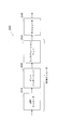
- FIG. 1 is a block diagram showing the configuration of a transmitter including a general BICM encoder.
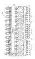
- FIG. 7 shows a parity check matrix of the RA QC LDPC code of FIG. 3 after row permutation.
- (A) It is a figure which shows the write-in process of the bit of the code word of 16K code (LDPC code whose LDPC code word length is 16200 bits) performed by 12 column-row interleavers, (b) is column-row. The figure which shows the read-out process of the bit of the code word written in (a) performed by the interleaver.
- (A) It is a figure which shows the write-in process of the bit of the code word of 16K code performed by 8 column-row interleavers, (b) is the code written by (a) performed by column-row interleaver
- FIG. 6 illustrates a potential problem for a 16K code in an 8 column DVB-T 2 bit interleaver.
- FIG. 6 illustrates a potential problem for a 16K code in a 12-sequence DVB-T 2 bit interleaver.
- FIG. 7 illustrates a potential problem when applying column twist processing to a 16K code in an 8-row DVB-T 2 bit interleaver.
- FIG. 7 illustrates a potential problem when applying column twist processing to a 16K code in a 12-column DVB-T 2 bit interleaver.
- (A) is a figure explaining the 1st condition which enables provision of the highly efficient interleaver which was found as a result of inventor's earnest research
- (b) demonstrates the 2nd condition Figure.
- FIG. 5 is a diagram showing a function of mapping by an interleaver according to an embodiment of the present invention. The block diagram which shows the structure of the interleaver which concerns on one Embodiment of this invention.
- FIG. 20 is a block diagram which shows the example of 1 structure of the section permutation unit which implements the section permutation of FIG. 20, (b) is a figure which shows the function of the mapping by the section permutation unit of (a).
- (A) is a block diagram which shows the other structural example of the section permutation unit which implements the section permutation of FIG. 20, (b) shows the function of the mapping by the section permutation unit of (a).
- Figure. The block diagram which shows the structure of the interleaver which concerns on other embodiment of this invention.
- FIG. 24 is a block diagram showing a configuration example of the bit interleaver of FIG. 23; The block diagram which shows one structural example of the transmitter which concerns on other embodiment of this invention.
- FIG. 24 is a block diagram showing a configuration example of the bit interleaver of FIG. 23; The block diagram which shows one structural example of the transmitter which concerns on other embodiment of this invention.
- FIG. 7 is a block diagram illustrating an example implementation of a BICM encoder according to yet another embodiment of the present invention.
- FIG. 7 is a block diagram illustrating an example configuration of a receiver having a non-iterative BICM decoder according to still another embodiment of the present invention.
- FIG. 10 is a block diagram illustrating an example configuration of a receiver having an iterative BICM decoder according to yet another embodiment of the present invention.
- FIG. 7 is a block diagram illustrating an example implementation of an iterative BICM decoder according to yet another embodiment of the invention. The figure which shows an example of the cyclic block of object of a parallel interleaver, and the cyclic block of non object.
- (A) is a figure explaining the 1st condition which enables provision of the highly efficient interleaver which was found as a result of inventor's earnest research
- (b) demonstrates the 2nd condition Figure.
- the block diagram which shows the structure of the interleaver which concerns on the further another embodiment of this invention.
- the block diagram which shows one structural example of a folding section permutation unit.
- FIG. 36 is a block diagram showing a configuration example of the interleaver of FIG. 35.
- the block diagram which shows one structural example of the transmitter which concerns on other embodiment of this invention.
- FIG. 7 is a block diagram illustrating an example configuration of a receiver having a non-iterative BICM decoder according to still another embodiment of the present invention.
- FIG. 10 is a block diagram illustrating an example configuration of a receiver having an iterative BICM decoder according to yet another embodiment of the present invention.
- FIG. 47 is a conceptual diagram showing connections in cyclic permutation to variable nodes of check nodes 17 to 24 of the parity check matrix shown in FIG. 46.
- (A) to (h) are diagrams showing mapping of variable nodes connected to check nodes 17 to 24, respectively, in the parity check matrix shown in FIG.
- FIGS. 49 (a)-(h) correspond to FIGS. 49 (a)-(h), respectively, and are diagrams showing that QB 14 is shifted by 2 in order not to include invalid check nodes.
- FIGS. 50 (a)-(h) respectively correspond to FIGS. 50 (a)-(h) and are diagrams showing that QB 4 is shifted by 3 in order not to include invalid check nodes.
- the conceptual diagram which shows the function structure of the parallel bit interleaver and cyclic block permutation which set the folding coefficient to 2 based on embodiment.
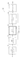
- FIG. 1 is a block diagram showing the configuration of a transmitter including a general bit-interleaved coding and modulation (BICM) encoder.
- the transmitter 100 shown in FIG. 1 comprises an input processing unit 110, a BICM encoder (including a low-density parity check (LDPC) encoder 120, a bit interleaver 130, a constellation mapper 140), and a modulator 150.
- a BICM encoder including a low-density parity check (LDPC) encoder 120, a bit interleaver 130, a constellation mapper 140
- LDPC low-density parity check
- the input processing unit 110 converts the input bit stream into multiple blocks of a predetermined length.
- the LDPC encoder 120 encodes the block into a codeword using an LDPC code and transmits the codeword to the bit interleaver 130.
- the bit interleaver 130 interleaves the LDPC code word, performs interleaving processing, and then divides it into a cell word (constellation word) sequence.
- Constellation mapper 140 maps each cell word (constellation word) to a sequence of constellations (eg, QAM).
- a general modulator 150 at the output end includes all processing blocks from the output of the BICM encoder to a Radio Frequency (RF) power amplifier.
- RF Radio Frequency
- An LDPC code is a linear error correction code which is completely defined by a parity check matrix (PCM).
- PCM is a binary sparse matrix and indicates a connection of codeword bits (also referred to as variable node) and parity check (also referred to as check node).
- the PCM columns and rows correspond to variable nodes and check nodes, respectively.
- the combination of the variable node and the check node is indicated by an element "1" in the PCM.
- the QC LDPC code has a configuration particularly suitable for hardware implementation. In fact, QC LDPC codes are used in most of today's standards.
- the PCM of the QC LDPC code has a special configuration having a plurality of cyclic matrices.
- a circulant matrix is a square matrix in which each row is in the form of one cyclic shift of elements in the row immediately before it, and one, two, or more folded diagonal columns May exist.
- the size of each circulant matrix is Q ⁇ Q.
- Q is referred to as a cyclic factor of the QC LDPC code.
- the pseudo-cyclic structure as described above allows Q check nodes to be processed in parallel, and QC LDPC codes are clearly advantageous codes for efficient hardware implementation.
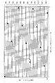
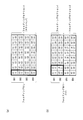
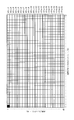
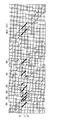
- one of the smallest squares represents one element of the PCM, and of these, the black square elements are “1”, and the other elements are “0”. It is.
- This PCM has a circulant matrix with one or two superimposed diagonal columns.
- the codeword bits are divided into blocks with Q bits.
- a block of cyclic coefficient Q bits is referred to herein as a cyclic block (or cyclic group).
- RA QC LDPC repeat-accumulate quasi-cyclic low-density parity check
- RA QC LDPC codes are known for their ease of coding and are adopted in a number of standards (eg, second generation DVB standards such as DVB-S2 standard, DVB-T2 standard, DVB-C2 standard) There is.
- the right side of the PCM corresponds to a parity bit, and the arrangement of the “1” element in that portion has a step structure.
- FIG. 3 exemplifies the PCM of the RA QC LDPC code whose coding rate is 2/3.
- DVB-T stands for Digital Video Broadcasting-Terrestrial
- DVB-S2 stands for Digital Video Broadcasting-Second Generation Satellite
- DVB-T2 stands for Digital Video Broadcasting-Second Generation Terrestrial
- DVB- C2 is an abbreviation of Digital Video Broadcasting-Second Generation Cable.
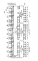
- the parity part of the PCM By performing appropriate permutation to change the order of bits only to the parity bits of the PCM shown in FIG. 4 subjected to the row permutation, the parity part of the PCM also has a pseudo cyclic structure.
- This technique is well known in the art, and is used under the name of parity interleaving or parity permutation in the DVB-T2 standard or the like.
- the PCM obtained as a result of applying parity permutation to the PCM shown in FIG. 4 is shown in FIG.
- LDPC codewords differ in significance from bit to bit, and constellations differ in robustness from bit to bit. Mapping the bits of the LDPC codeword directly to the constellation, ie without interleaving, does not lead to optimum performance. For this reason, the bits of the LDPC code word need to be interleaved before mapping the bits of the LDPC code word to the constellation.
- a bit interleaver 130 is provided between the LDPC encoder 120 and the constellation mapper 140. Careful design of the bit interleaver 130 improves the relevancy between bits of the LDPC codeword and bits encoded by the constellation, leading to improved reception performance. Its performance is usually measured using Bit Error Rate (BER) as a function of Signal to Noise Ratio (SNR).
- BER Bit Error Rate
- SNR Signal to Noise Ratio
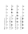
- a complex quadrature amplitude modulation (QAM) constellation consists of two independent pulse amplitude modulation (PAM) symbols, one corresponding to the real part and one to the imaginary part. It corresponds.
- the two PAM symbols each encode the same number M of bits.
- FIG. 6 which shows 8 PAM symbols using Gray codes
- the robustness levels of the bits encoded in one PAM symbol are different from each other.
- the reason why the robustness levels are different from one another is that the distance between two subsets defined by each bit (0 or 1) is different for each bit. The larger this distance, the higher the robustness level or reliability of the bit.
- the robust level of bit b3 is the highest and the robust level of bit b1 is the lowest.
- a 16 QAM constellation encodes 4 bits and has 2 robust levels.
- the 64 QAM constellation encodes 6 bits and has 3 robust levels.
- a 256 QAM constellation encodes 8 bits and has 4 robust levels.
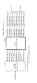
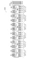
- FIG. 7 is a block diagram showing the configuration of a general interleaver corresponding to the above parameters.
- QB1, ..., QB12 are 12 cyclic blocks
- C1, ..., C24 are 24 constellation words.
- bit interleaver 710 interleaves the 96 bits of the LDPC codeword.
- DVB-T2 As a conventional bit interleaver, one of the DVB-T2 standard (ETSI EN 302 755) is known.
- the DVB-T2 standard is an improvement on the DVB-T standard which is a television standard, and describes a second generation baseline transmission system for digital terrestrial television broadcasting.
- the DVB-T2 standard details channel coding modulation systems for transmitting digital television services and general data.
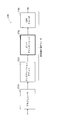
- FIG. 8A is a block diagram showing the configuration of a modulator (DVB-T2 modulator) used in the DVB-T2 standard.
- the DVB-T2 modulator 800 shown in FIG. 8 (a) comprises an input processing unit 810, a BICM encoder 820, a frame builder 830 and an OFDM generator 840.
- the input processing unit 810 converts the input bit stream into blocks of a predetermined length.
- the BICM encoder 820 performs BICM processing on the input.
- the frame builder 830 generates a DVB-T2 transmission frame configuration using inputs from the BICM encoder 820 and the like.
- the OFDM generator 840 performs pilot addition, high-speed inverse Fourier transform, guard interval insertion, and the like on the transmission frame configuration of the DVB-T2 system, and outputs a transmission signal of the DVB-T2 system.
- FIG. 8B is a block diagram showing the configuration of the BICM encoder 820 of the DVB-T2 modulator shown in FIG. 8A. However, in FIG. 8B, BCH outer coding, constellation rotation, cell interleaver, time interleaver and the like are omitted.
- the BICM encoder 820 includes an LDPC encoder 821, a bit interleaver (including a parity interleaver 822 and a column-row interleaver 823), a bit-cell demultiplexer 824, and a QAM mapper 825.
- the LDPC encoder 821 encodes a block into a codeword using an LDPC code.
- the bit interleaver (parity interleaver 822 and column-row interleaver 823) performs interleaving processing to change the order of the bits of the code word.
- the bit-cell demultiplexer 824 demultiplexes the interleaved codeword bits into cell words (constellation words).
- the QAM mapper 825 maps cell words (constellation words) to complex QAM symbols.
- the complex QAM symbol is also referred to as a cell.
- the bit-cell demultiplexer 824 may be considered to be part of a bit interleaver.
- a BICM encoder based on the DVB-T2 standard can be regarded as having the standard configuration shown in FIG.
- two codewords of 16200 bits and 64800 bits are defined.
- An LDPC code having a codeword length of 16200 bits and an LDPC code having a codeword length of 64800 bits are referred to herein as a 16K code (or 16K LDPC code) and a 64K code (or 64K LDPC code).
- the number of cyclic blocks included in one code word is 45 for the 16K code and 180 for the 64K code.
- the usable codes corresponding to these two block lengths (code word lengths) are listed in Table A.1 of ETSI EN 302 755, which is a DVB-T2 standard. 1 to Table A. 6 listed.
- the bit interleaver is used only for constellations larger than QPSK and comprises a parity interleaver 822, a column-row interleaver 823 and a bit-cell demultiplexer 824. Note that, in the definition of the DVB-T2 standard, the bit-cell demultiplexer 824 is not included in the bit interleaver. However, since the present invention relates to interleaving applied to an LDPC code before constellation mapping, the bit-cell demultiplexer 824 is also treated as part of bit interleaving.
- the parity interleaver 822 performs parity permutation to change the order of parity bits of the codeword in order to clarify the pseudo-cyclic structure of parity bits.
- the column-row interleaver 823 works conceptually by writing the bits of the LDPC codeword along the columns of the interleaver matrix and reading them along the rows. The first bit contained in the LDPC code word is written first and read first. The column-row interleaver 823 shifts the bits cyclically by a predetermined number of positions with respect to the column after writing the bits of the LDPC code word and before starting reading the bits. This is called column twisting in the DVB-T2 standard. The number of columns Nc and the number of rows Nr of the interleaver matrix corresponding to the above two LDPC codeword lengths and various constellation sizes are shown in Table 1 below.
- the number of columns Nc is twice the number of bits of one constellation, except in the case of a 16K code in a 256 QAM constellation.
- the reason for this exception is that the LDPC codeword length of 16200 is not a multiple of 16, ie twice the number of bits in the 256 QAM constellation.
- bit-cell demultiplexer 824 demultiplexes each LDPC codeword to obtain multiple parallel bit streams.
- the number of streams is twice that of the number M of bits encoded in one QAM constellation, ie 2 ⁇ M, except in the case of a 16K LDPC code in a 256 QAM constellation.
- the number of streams is M, the number of bits encoded in one QAM constellation.
- M bits encoded in one constellation are referred to as cell words (or constellation words). As described below, in a 16K LDPC code, the number of cell words obtained from one code word is 16200 / M.
- the bit-cell demultiplexer comprises a simple demultiplexer 1110 (1210, 1310) and a demultiplexing permutation unit 1120 (1220, 1320), as shown in FIG. 11 (FIGS. 12, 13).
- bit-cell demultiplexer in addition to simply demultiplexing the interleaved LDPC codeword by the simple demultiplexer 1110 (1210, 1310), by the demultiplexing unit 1120 (1220, 1220) Permutation processing is performed on the demultiplexed parallel bit stream to change its order.
- bit interleaver used in the DVB-T2 standard comes with two problems.
- the first problem is that parallelism is lost when the number of cyclic blocks in an LDPC codeword is not a multiple of the number of columns of the bit interleaver matrix. Latency increases as parallelism decreases. This is particularly a problem when iterative BICM decoding is used at the receiver. This situation occurs with some of the combinations of LDPC codeword length and constellation size for the DVB-T2 standard.
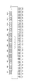
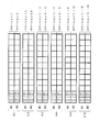
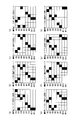
- FIGS. 14 and 15 are diagrams showing the above-mentioned situation which occurs when the number of columns of the interleaver matrix is 8 and 12, respectively, in the 16K LDPC code.
- 16 QAM and 256 QAM constellations an 8-row interleaver matrix is used.
- 64 QAM constellation a 12-column interleaver matrix is used.
- a grid represents an LDPC code word
- a small square represents one bit of the LDPC code word
- a row corresponds to a cyclic block
- a column corresponds to a bit having the same bit index as each other in a plurality of cyclic blocks.
- Filled squares represent 8 bits and 12 bits in the first row of the interleaver matrix.
- the second problem is that in the DVB-T2 standard, the number of possible bit interleaver configurations is limited by the number of columns of the bit interleaver matrix.
- FIGS. 16 and 17 show the same situation as in FIGS. 14 and 15, respectively, except that column twist processing is applied.
- the column twist value for each column used in the DVB-T 2-bit interleaver is (0, 0, 0, 1, 7, 20, 20, 21).
- the column twist value for each column used in the DVB-T 2-bit interleaver is (0, 0, 0, 2, 2, 2, 3, 3, 3, 6, 7, 7).
- Embodiment (Part 1) ⁇ Embodiment (Part 1) >>
- bit interleaver parallel bit interleaver
- the same reference numerals are given to constituent units that perform substantially the same processing content and the same processing content.
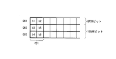
- each of a group of M cyclic blocks or each of a group of Q constellation words is called a section (or an interleaver section).
- It is a block diagram which shows one structural example of a figure and the said bit interleaver.
- one section permutation unit is used to perform three section permutation processing to be described later while switching the processing target in time series. May be
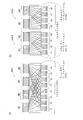
- the section permutation units (2021, 2022, 2023) are independent of each other (independently of each other), and each of eight constellation words (C1 to C8, C9 to C16, C17 to C24) is 4 Section per order to change the order of a total of 32 bits of 4 cyclic blocks so that 1 bit is mapped from each of 2 cyclic blocks (QB1 to QB4, QB5 to QB8, QB9 to QB12) Perform a mutation process.
- the two conditions 1 and 2 described above are merely to ensure that the bit interleaver is divided into N / M parallel sections.
- the same permutation rule may be applied to the section permutation processing applied to these parallel sections, or different permutation rules may be applied, or only some of them may be identical to each other. Mutation rules may be applied.
- the section permutation unit maps Q bits of a cyclic block (equal in importance in the LDPC decoding process) to bits of the same bit index of Q constellation words (robust levels are equal to one another). You may do it.
- the Q bits can be arranged sequentially or in permutation order. The latter will be described using FIGS. 21 (a) and 21 (b) and the former using FIGS. 22 (a) and 22 (b).
- FIG. 21A shows an example of the configuration of the section permutation unit shown in FIG.
- Section permutation unit 2101 includes intra-cyclic block permutation units 2111-2114 and column-row permutation unit 2131. It should be noted that instead of providing four intra-cyclic block permutation units, for example, four intra-cyclic block permutations to be described later while switching processing targets in time series using one intra-cyclic block permutation unit. Processing may be performed.
- the intra-cyclic block permutation unit (2111 to 2114) performs intra-cyclic block permutation processing for changing the order of the Q (8) bits of the cyclic blocks (QB1 to QB4).
- the same permutation rule may be applied to the intra-cyclic block permutation processing applied to cyclic blocks in one section, or different permutation rules may be applied. Only part of the permutation rules may be applied to each other.
- the column-row permutation unit 2131 performs column-row permutation processing to change the order of M ⁇ Q (32) bits. Specifically, the column-row permutation unit 2131 writes M ⁇ Q (32 bits) in the row direction of a matrix of Q columns and M rows (8 columns and 4 rows), and writes M ⁇ Q pieces Column-row permutation processing equivalent to reading (32) bits in the column direction is performed. In the column-row permutation processing by the column-row permutation unit 2131, the 12th row 1350 rows in FIGS. 9A and 9B are replaced with the Q row M row, and the write processing is from the column direction to the row direction In addition, the reading process is changed from the row direction to the column direction.
- FIG. 21 (b) is a view showing the function of mapping by the section permutation unit of FIG. 21 (a).
- M 4 bits of each constellation word are indicated by b1 to b4.
- intra-cyclic block permutation processing may not be performed in the section permutation processing.
- FIG. 22 (b) Another example of the section permutation in FIG. 20, one configuration example of the section permutation unit not carrying out the intra-cyclic block permutation processing and the function of the mapping by this section permutation unit are shown in FIG. And FIG. 22 (b).
- the section permutation unit 2201 has a column-row permutation unit 2131 and performs only column-row permutation processing.
- M 4 bits of each constellation word are indicated by b1 to b4.
- section permutation described in FIGS. 21 and 22 may be performed on cyclic blocks QB5 to QB8 and QB9 to QB12.
- the bit interleaver additionally performs cyclic block permutation processing to rearrange the order of N cyclic blocks before performing section permutation processing.
- One configuration example of a bit interleaver that additionally performs cyclic block permutation processing is shown in FIG.
- the cyclic block permutation here plays the same role as the permutation by the bit-cell demultiplexer in the DVB-T2 standard.
- the bit interleaver 2300 shown in FIG. 23 includes a cyclic block permutation unit 2310 and a bit permutation unit 2010 (including section permutation units 2021 to 2023).
- the cyclic block permutation unit 2310 performs cyclic block permutation processing 2311 to 2318 for changing the order of the cyclic blocks QB1 to QB12. Note that permutation rules used in cyclic block permutation processing 2311 to 2318 are the same as one another.
- Cyclic block permutation applied to N cyclic blocks is particularly useful because it enables optimal mapping of bits of an LDPC codeword to bits of a constellation, leading to optimization of reception performance. is there.
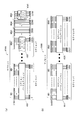
- FIG. 24 is a block diagram showing one configuration example of the bit interleaver of FIG.
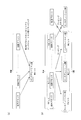
- the bit interleaver 2400 of FIG. 24 performs the following three permutation processes of stages A, B and C.
- Stage A cyclic block (inter) permutation
- Stage B intra-cyclic block permutation
- Stage C column-row permutation
- the cyclic block (inter) permutation is N cycles constituting a codeword Permutation to change the order of blocks
- in-block permutation is permutation to change the order of Q bits that make up a cyclic block
- column-row permutation forms sections It is a permutation that changes the order of M ⁇ Q bits to be processed.
- the bit interleaver 2400 shown in FIG. 24 includes a cyclic block permutation unit 2310 and a bit permutation unit 2010 (section permutation units 2101 to 2103).
- the section permutation unit 2101 (2102, 2103) includes intra-cyclic block permutation units 2111 to 2114 (2115 to 2118, 2119 to 2122) and column-row permutation units 2131 (2132, 2133).
- the bit interleaver 2400 performs cyclic block (interleave) permutation by the cyclic block permutation unit 2310 (stage A), and performs intra cyclic block permutation by the intra cyclic block permutation units 2111 to 2122 (stage B) Column-row permutation is performed by column-row permutation units 2131 to 2133) (stage C).
- the intra-cyclic block permutation units 2111 to 2122 may be removed from the bit interleaver shown in FIG. 24 so that the intra-cyclic block permutation is not performed. Also, the bit interleaver may perform intra-cyclic block permutations before cyclic block (inter) block permutations instead of performing after cyclic block (inter-block) permutations; Between) may be performed before and after the permutation.
- the plurality of intra-cyclic block permutation units may have the same configuration. Therefore, a plurality of intra-cyclic block permutation units can be implemented by the same functional resource (such as a hardware block). Also, the plurality of intra-cyclic block permutations may consist of cyclic shift processing, in which case efficient hardware implementation using a barrel shifter is possible. It is also possible to implement using the barrel shifter used for the LDPC decoder.
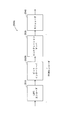
- FIG. 25 is a block diagram showing an exemplary configuration of a transmitter according to still another embodiment of the present invention.
- the transmitter 2500 shown in FIG. 25 includes a BICM encoder (including an LDPC encoder 2510, a bit interleaver 2520, and a constellation mapper 2530) and a modulator 2540.
- the LDPC encoder 2510 encodes the input block into a codeword using a QC-LDPC code, and outputs the codeword to the bit interleaver 2520.
- bit interleaver 2520 additionally performs cyclic block permutation processing described, for example, in FIGS. 23 to 24 or as a modification thereof in addition to bit permutation processing as bit interleaving processing. May be
- Constellation mapper 2530 receives a constellation word from bit interleaver 2520 and performs constellation mapping processing on the received constellation word.
- the modulator 2740 performs orthogonal frequency division multiplexing (OFDM) modulation or the like to generate a transmission signal.
- OFDM orthogonal frequency division multiplexing
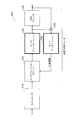
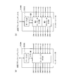
- FIG. 26 is a block diagram showing an implementation example of a BICM encoder according to still another embodiment of the present invention.
- the BICM encoder 2600 shown in FIG. 26 includes a main memory 2601, an LDPC controller 2611, a rotator 2612, a check node processor group 2613, a derotator 2614, a QB counter 2631, a table 2632, an interleaver 2633, a register group 2634, an interleaver 2635, and a mapper.
- a group 2651 is provided.
- the main memory 2601 receives a bit string to be transmitted, for example, from an input processing unit (not shown), and holds the received bit string.
- the LDPC controller 2611 outputs a read address to the main memory 2601, whereby the main memory 2601 outputs eight bits from the beginning of the bit string to the rotator 2612.
- the rotator 2612 cyclically shifts the predetermined number of 8 bits supplied from the main memory 2601 under the control of the LDPC controller 2611, and shifts the eight bits after cyclic shift to each check node processor of the check node processor group 2613. Output bit by bit.
- Each check node processor of each check node processor group 2613 performs check node processing on the input 1 bit under the control of the LDPC controller 2611, and outputs the 1 bit processing result to the derotator 2614.
- Derotator 2614 cyclically shifts the eight bits received from check node processor group 2613 a predetermined number so as to cancel the cyclic shift by rotator 2612 under the control of LDPC controller 2611, and sends the eight bits after cyclic shift to main memory 2601. Output.
- the LDPC controller 2611 outputs a write address to the main memory 2601, whereby the main memory 2601 holds 8 bits supplied from the derotator 2614.
- the LDPC controller 2611, the rotator 2612, the check node processor group 2613, and the derotator 2614 constitute an LDPC encoder 2510 of the BICM encoder in FIG.
- the QB counter 2631 counts from 0 to 11, and outputs the counter value to the table 2632.
- the read address is output.
- the main memory 2601 outputs, to the interleaver 2633, bits for one cyclic block corresponding to the counter value of the QB counter 2631.
- the cyclic block permutation (stage A) is realized by the processing of this table 2632.
- the interleaver 2633 cyclically shifts the bits for one cyclic block supplied from the main memory 2601 by a predetermined number and outputs the result to the first stage register of the register group 2634.
- intra-cyclic block permutation stage B is realized by the processing of the interleaver 2633.
- each register of the register group 2634 holds the bits for one cyclic block at the timing when the control pulse is received, and continues to output the held bits for one cyclic block until the control pulse is next received.
- the bits (32 bits) for 4 cyclic blocks are input to the interleaver 2635.
- M 4 bits
- the QB counter 2631, the table 2632, the interleaver 2633, the register group 2634, and the interleaver 2635 constitute a bit interleaver 2520 of the BICM encoder in FIG.
- mapper group 2651 maps the 4 bits supplied from the interleaver 2635 into a constellation, and outputs the mapping result.
- mapper group 2651 constitutes constellation mapper 2530 of the BICM encoder in FIG.
- the above series of processing is performed three times for one code word, in total, from the counter values “0” to “3”, “4” to “7”, and “8” to “11” of the QB counter 2631.
- FIG. 26 includes Q mappers operating in parallel
- Q mappers operating in parallel
- the parallelism can be easily increased by increasing the number of parallel interleaver sections in the bit interleaver, ie N / M.
- parallelization can be maximized by parallelizing Q ⁇ N / M mappers.
- Bit interleavers have the advantage that such parallelism can be realized without any obstacles.
- FIG. 27 is a block diagram showing an example configuration of a receiver having a non-iterative BICM decoder according to still another embodiment of the present invention. The receiver operates in reverse to the transmitter.
- the receiver 2700 shown in FIG. 27 comprises a modulator 2710 and a non-iterative BICM decoder (including constellation demapper 2720 and bit deinterleaver 2730, LDPC decoder 2740).
- the demodulator 2710 performs demodulation processing using OFDM or the like, and outputs the demodulation processing result.
- Constellation demapper 2720 of the non-repetitive BICM decoder demaps the input from modulator 2710 to generate a so-called soft bit string, and outputs the generated soft bit string to constellation demapper 2730.
- Each soft bit is a measure of the probability that each bit will be 0 or 1.
- soft bits are represented by log likelihood ratios (LLRs) and defined as follows.
- the bit deinterleaver 2730 interleaves the soft bit sequence output from the constellation demapper 2720 by the bit interleaver in the transmitter of FIG. (Bit de-interleaving processing) is performed.
- the LDPC decoder 2740 receives the soft bit sequence subjected to bit deinterleaving from the bit deinterleaver 2730, and performs an LDPC decoding process using the received soft bit sequence.
- FIG. 28 is a block diagram showing an example of configuration of a receiver having an iterative BICM decoder according to still another embodiment of the present invention. The receiver operates in reverse to the transmitter.
- the receiver 2800 shown in FIG. 28 includes a modulator 2710 and an iterative BICM decoder (constellation demapper 2720, bit deinterleaver 2730, LDPC decoder 2740, subtraction unit 2760, bit interleaver 2750).
- BICM decoder castellation demapper 2720, bit deinterleaver 2730, LDPC decoder 2740, subtraction unit 2760, bit interleaver 2750.
- the receiver 2800 in FIG. 28 performs constellation demapping processing by the constellation demapper 2720, bit deinterleaving processing by the bit deinterleaving 2730, and LDPC decoding processing by the LDPC decoder 2740.
- a subtraction unit 2760 subtracts the input of the LDPC decoder 2740 from the output of the LDPC decoder 2740, and extrinsic information obtained as a result of the subtraction is bit interleaver Output to 2750.
- the bit interleaver 2750 performs interleaving on the external information in the same interleaving rule as the bit interleaving performed on the bit sequence by the bit interleaver in the transmitter of FIG. Then, bit interleaver 2750 feeds back the interleaved external information to constellation demapper 2720. Constellation demapper 2720 uses the fed-back external information as a-priori information to calculate a more reliable LLR value.
- bit deinterleaver 2730 cancels the bit interleaving processing applied to the bit string by the bit interleaver in the transmitter of FIG. 25 to the newly calculated LLR value and restores the original order (bit deinterleaver Interleave processing).
- the LDPC decoder 2740 performs an LDPC decoding process using the LLR value subjected to the bit deinterleaving process.
- the iterative decoding loop consists of four elements: constellation demapper 2720, bit deinterleaver 2730, LDPC decoder 2740, and bit interleaver 2750.
- the bit deinterleaver 2730 and the bit interleaver 2750 have very low latency, ideally zero, and a simple configuration allows efficient implementation of the receiver.
- the above-described bit deinterleaver 2730 and bit interleaver 2750 satisfy both conditions.
- FIG. 1 One implementation of the iterative BICM decoder that implements a very efficient parallel implementation is described using FIG.
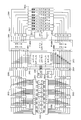
- FIG. 29 is a block diagram showing an implementation example of a BICM decoder according to still another embodiment of the present invention.
- the BICM decoder 2900 shown in FIG. 29 includes a main LLR memory 2901, a buffer LLR memory 2902, an LDPC controller 2911, a rotator 2912, a check node processor group 2913, a derotator 2914, a QB counter 2931, a table 2932, a subtraction unit 2933, an interleaver 2934, A register group 2935, an interleaver 2936, a demapper group 2937, a deinterleaver 2938, a register group 2939, a deinterleaver 2940, and a delay unit 2941 are provided.
- demapper of the demapper group 2937 performs demapping processing using the output of the demodulator (not shown), and outputs the LLR value obtained thereby to the deinterleaver 2938.
- demapper group 2937 constitutes constellation demapper 2720 of the iterative BICM decoder in FIG.
- the deinterleaver 2938 performs deinterleaving processing (interleaving processing to cancel interleaving by the stage C by the transmitter) on the LLR value, and outputs the LLR value after deinterleaving to each register of the register group 2939.
- LLR values (eight LLR values) for one circulating block are stored in each of the registers.
- the LLR values for one cyclic block held in the registers are sequentially output to the subsequent stage, and the held contents of the respective registers are sequentially updated.
- the deinterleaver 2940 performs interleaving processing (interleaving processing to cancel interleaving by the stage B by the transmitter) on the LLR values (eight LLR values) for one cyclic block to be supplied, and stores the contents of the table 2932 ( The main LLR memory 2901 and the buffer LLR memory 2902 are written according to the following description). Note that, by writing to the main LLR memory 2901 and the buffer LLR memory 2902 in accordance with the contents held in the table 2932, interleaving processing to cancel interleaving by the stage A by the transmitter is realized.
- the main LLR memory 2901 stores the LLR value after the de-interleaving process, and is also used by the LDPC decoder (LDPC controller 2911, rotator 2912, check node processor group 2913, derotator 2914).
- the LDPC decoding process is an iterative process consisting of one or more iterations. At each iteration of the LDPC decoding process, the LLR values in the main LLR memory 2901 are updated. The old LLR values are held in the buffer LLR memory 2902 to calculate the extrinsic information needed for the iterative BICM decoding process.
- the LDPC controller 2911 outputs the read address to the main LLR memory 2901 according to the parity check matrix of the LDPC code, whereby the main LLR memory 2901 sequentially outputs LLR values to the rotator 2912 for each one of the cyclic blocks.
- the rotator 2912 cyclically shifts the LLR values for one cyclic block sequentially supplied from the main LLR memory 2901 by a predetermined number under the control of the LDPC controller 2911, and the LLR values after cyclic shift are of the check node processor group 2913. Output one by one to each check node processor.
- Each check node processor of each check node processor group 2913 performs check node processing on a series of LLR values sequentially input under control of the LDPC controller 2911.
- each check node processor of the check node processor group 2913 receives control of the LDPC controller 2911 and sequentially outputs a series of LLR values as a result of check node processing.
- the derotator 2914 cyclically shifts the processing result for one cyclic block sequentially received from the check node processor group 2913 by a predetermined number so as to cancel the cyclic shift by the rotator 2912 under the control of the LDPC controller 2911 and cyclic shift
- the processing results are sequentially output to the main LLR memory 2901.
- the LDPC controller 2911 outputs a write address to the main LLR memory 2901 according to the parity check matrix of the LDPC code, whereby the main LLR memory 2901 holds the processing result for one cyclic block sequentially supplied from the derotator 2914. .
- the LDPC controller 2911 repeatedly executes the above processing in accordance with the parity check matrix of the LDPC code.
- BICM iterations are performed.
- LDPC and BICM iterative processes are also referred to as internal and external iterative processes, respectively.
- the BICM and LDPC decoding processes are well known in the art and will not be described in detail.
- the QB counter 2931 counts from 0 to 11, and outputs the counter value to the table 2932.
- the main LLR memory 2901 is supplied so that LLR values for one cyclic block corresponding to the counter value supplied from the QB counter 2931 are supplied from the main LLR memory 2901 and the buffer LLR memory 2902 to the subtraction unit group 2933. And outputs the read address to the buffer LLR memory 2902.
- main LLR memory 2901 and buffer LLR memory 2902 each output LLR values for one cyclic block corresponding to the counter value of QB counter 2931 to subtraction unit 2934.
- the delay position by the delay unit 2941 is set so that the reading position of the LLR value from the main LLR memory 2901 and the buffer LLR memory 2902 and the writing position of the LLR value to the main LLR memory 2901 and the buffer LLR memory 2902 coincide with each other. Adjustments will be made. Note that the permutation corresponding to the cyclic block permutation (stage A) is realized by the processing of the table 2932.
- Each subtraction unit 2933 of the subtraction unit group subtracts the output of the buffer LLR memory 2902 from the output of the main LLR memory 2901 and obtains external information (eight external information) for one cyclic block obtained as a result of subtraction. Output to interleaver 2934.
- the interleaver 2934 cyclically shifts the external information for one cyclic block supplied from the subtraction unit 2933 by a predetermined number and outputs the information to the first stage register of the register group 2935.
- the processing corresponding to the intra-cyclic block permutation (stage B) is realized by the processing of the interleaver 2934.
- each register of the register group 2935 receives a control pulse and holds 8 bits, and keeps holding the held 8 bits until the next control pulse is received.
- the interleaver 2936 receives external information (32 external information) for 4 cyclic blocks. .
- M 4 for each demapper of the demapper group 2937
- the QB counter 2931, the table 2932, the interleaver 2934, the register group 2935, and the interleaver 2936 constitute a bit interleaver 2750 of the BICM decoder in FIG.
- Each demapper of the demapper group 2937 performs demapping processing using the four pieces of external information supplied from the interleaver 2936 as prior information, and outputs a new LLR value to the deinterleaver 2938.
- the deinterleaver 2938 performs deinterleaving processing (interleaving processing to cancel interleaving by the stage C by the transmitter) on the LLR value, and outputs the LLR value after deinterleaving to each register of the register group 2939.
- LLR values (eight LLR values) for one circulating block are stored in each of the registers.
- the LLR values for one cyclic block held in the registers are sequentially output to the subsequent stage, and the held contents of the respective registers are sequentially updated.
- the deinterleaver 2940 performs deinterleaving processing (interleaving processing to cancel interleaving by the stage B by the transmitter) on the LLR values (eight LLR values) for one cyclic block to be supplied, and the main LLR memory 2901 and Output to buffer LLR memory 2902.
- the main LLR memory 2901 and the buffer LLR memory 2902 receive the write address from the table 2932 via the delay unit 2941, and according to the received write address, the LLR values for one cyclic block received from the deinterleaver 2940 (eight Hold LLR value).
- the write processing according to the table 2932 realizes interleaving processing (de-interleaving processing) that cancels interleaving by the stage A by the transmitter.
- the above series of processing is performed three times for one code word, in total, from the counter values “0” to “3”, “4” to “7”, and “8” to “11” of the QB counter 2931.
- the QB counter 2931, the table 2932, the deinterleaver 2938, the register group 2939, and the deinterleaver 2940 constitute a bit deinterleaver 2730 of the BICM decoder in FIG. 28.
- Interleaver 2934 and de-interleaver 2940 are reconfigurable and have a constant hardware cost, but the cost can be minimized by careful design.
- Interleaver 2936 and de-interleaver 2938 implement column-row permutation, which is constant for a given constellation size. Therefore, the implementation cost is small.
- FIG. 29 includes Q demappers operating in parallel
- the parallelism can be easily increased by increasing the number of parallel interleaver sections in the bit interleaver, ie N / M.
- parallelization can be maximized by parallelizing Q ⁇ N / M demappers.
- the bit interleaver described above has the advantage that such parallelism can be realized without any obstacles.
- the bit interleaver selects N ′ cyclic blocks that are multiples of the number M of bits of the constellation word among the N cyclic blocks.
- the bit interleaver divides the selected N ′ cyclic blocks into N ′ / M sections so that each includes M cyclic blocks, and performs section permutation on each section.
- the bits of the excluded (not selected) cyclic block may not be interleaved or may be interleaved.
- a bit interleaving method is a bit interleaving method in a communication system using a pseudo-cyclic low density parity check code, and the bit interleaving method includes N cycles each consisting of Q bits.
- a receiving step of receiving a codeword of the pseudo-cyclic low density parity check code composed of blocks, and a bit permutation process of performing bit permutation processing of changing the order of bits of the codeword to the bits of the codeword A plurality of mutation steps and codewords subjected to the bit permutation process, each of which comprises M bits, each of which indicates any one of 2 M constellation points of a predetermined constellation.
- the codeword before being subjected to the telecommunication processing is divided into N '/ M sections, and each of the sections consists of the M cyclic blocks, and each of the constellation words is the N' / M Associated with one of the sections, the bit permutation step consists of one bit of each of the M different cyclic blocks in the section to which each of the constellation words is associated. A total of M bits, and all the bits of each said section are associated with that section. The bit permutation process is performed so as to be mapped only to the word.
- a bit interleaver is a bit interleaver in a communication system using a pseudo-cyclic low density parity check code, wherein the bit interleaver is configured to generate N cyclic circuits each consisting of Q bits.
- a codeword of the pseudo cyclic low density parity check code composed of blocks is received, and bit permutation processing is performed on the bits of the codeword to change the order of bits of the codeword, and the bit permutation is performed.
- the bit permutation unit includes a total of M bits each consisting of one bit of each of the M different cyclic blocks in the section associated with each of the constellation words.
- bits of the section are mapped only to the Q constellation words associated with the section
- the present invention is characterized in that the bit permutation process is performed.
- the bits of the code word are not included in the subset of the selected N ′ cyclic blocks, and a group of bits to be left as targets for changing the order of bits, or the selected N It does not matter if it includes a group of bits which are targets of changing the order of bits independent of the bit permutation process, which is applied only to the cyclic blocks which are not included in the cyclic block and not selected. .
- the excluded cyclic block may be the one with the smallest variable node weight.
- the excluded cyclic block may be a cyclic block of the parity part (having a variable node of weight 2), in this case, for example, from the end of the codeword It may be one or more cyclic blocks.
- the selecting step may select the cyclic block based on the degree of importance of bits included in each cyclic block.
- the importance of the bits included in each cyclic block may be determined based on the number of associated parity bits.
- the code word may be a repeat accumulated pseudo cyclic low density parity check code, and the non-selected cyclic block may correspond to a parity section of the code word.
- the selected subset of N ′ cyclic blocks may be configured by N ′ blocks that are continuous from the cyclic block having the first bit of the codeword.
- FIG. 30 is a diagram illustrating a cyclic block to which the interleaving method described in the embodiment is applied (the cyclic block to be excluded) and a cyclic block to which the interleaving method is applied is not applied.
- FIG. 30 is a diagram for the case where the code is a 16K LDPC code defined in the DVB-T2 standard and the constellation is a 16 QAM constellation. In the example of FIG.
- the cyclic block to be applied is 44 cyclic blocks (1,..., 44), and the cyclic blocks not to be applied (cyclic blocks to be excluded) are one in the last row. This is only the cyclic block 45. Also, four black squares represent four bits of the first constellation word.
- the number of interleaver sections is floor (N / M), and the number of cyclic blocks excluded is rem (N, M).
- floor (N / M) is a function that returns the largest integer value of N / M or less
- rem (N, M) is a function that returns a remainder value obtained by dividing N by M.
- each constellation word is mapped to M cyclic blocks.
- a very large number of delay registers are required (FIGS. 26 and 29). See the implementation example described in The use of very large delay registers leads to increased circuit area and power consumption.
- reducing the number of cyclic blocks to which the constellation word is mapped is beneficial to increase the overlap between the outer (BICM) and inner (LDPC) iterations, and the overall BICM Reduce decoding latency.
- the number of cyclic blocks to which the constellation word is mapped can be reduced.
- the number of bits of the constellation word mapped to the same cyclic block is referred to as a folding coefficient and denoted as F.
- F the folding coefficient
- the constellation word is mapped to only 2 cyclic blocks instead of 4 cyclic blocks.
- Complex QAM constellation symbols can be separated into two equal real pulse-amplitude modulation (PAM) symbols.
- PAM pulse-amplitude modulation
- the M bits of the QAM constellation can be divided into a set of M / 2 bits of two equivalent real PAM symbols, and the bits of the constellation word can be mapped to the same M / 2 cyclic blocks it can.
- the folding factor where F 2 is a useful value for QAM constellations.
- Folding has the added benefit of reducing the number of excluded cyclic blocks or zeroing out the number of excluded cyclic blocks.
- the inventor has found that it is necessary to change the conditions 1 and 2 to the following conditions 1A and 2A in order to perform folding (F is an integer of 2 or more).
- F 1 means no folding, and conditions 1A and 2A are the same as conditions 1 and 2.
- each of a group of M / F cyclic blocks or each of a group of Q / F constellation words is referred to as a folding section (or a folding interleaver section).
- the folding interleaver section matches the interleaver section, and the bit interleaver has the same configuration as the bit interleaver of the embodiment (part 1).
- the folding section permutation units (2021A, 2022A, 2023A, 2024A, 2025A, 2026A) are independent of one another (independently of one another) and four constellation words (C1-C4, C5-C8, C9).
- M / F 2 cyclic blocks (QB1 to QB2, QB3 to QB4, QB5 to QB6, QB7 to QB8, QB9 to QB10, QB11) for each of C12 to C12, C13 to C16, C17 to C20, and C21 to C24).
- the above two conditions 1A and 2A are merely to ensure that the bit interleaver is divided into F ⁇ N / M parallel folding sections.
- the same permutation rules may be applied to the folding section permutation processing applied to these parallel folding sections, or different permutation rules may be applied, or only some of them may be applied.
- the same permutation rules may be applied to each other.
- the constellation is a 16 QAM constellation. Therefore, there are two robust levels in the bits of the constellation, and the bits b1 and b3 are the same robust level, and the bits b2 and b4 are the same robust level.
- the folding section permutation unit 2201A (2202A) has a column-row permutation unit 2131A (2132A).
- folding of the folding coefficient F reduces the number of cyclic blocks mapped to one constellation word. This reduces the number of matrix rows in column-row permutation from M to M / F.
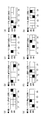
- FIG.33 (a) is a figure which shows the function of the mapping by the (folding) section permutation unit of Fig.34 (a)
- FIG.33 (b) is two folding sections of FIG.34 (a). It is a figure which shows the function of the mapping by a permutation unit.
- M 4 bits of each constellation word are indicated by b1 to b4.
- the portions surrounded by thick lines represent the mapping for the constellation word C1.
- eight bits (having the same importance) of one cyclic block are bits having the same bit index of eight constellation words (having the same robustness level). Is mapped to). Also, in the example of FIGS. 33 (b) and 34 (b), 8 bits (having the same importance) of one cyclic block are mapped to bits of the same robust level of 4 constellation words. .
- folding section permutation described in FIG. 34B may be performed on the cyclic blocks QB5 to QB6, QB7 to QB8, QB9 to QB10, and QB11 to QB12.
- the bit interleaver performs cyclic block permutation processing to additionally change the order of N cyclic blocks before performing folding section permutation processing. I do.
- An exemplary configuration of a bit interleaver that additionally performs cyclic block permutation processing is shown in FIG.
- the bit interleaver 2300A shown in FIG. 35 includes a cyclic block permutation unit 2310 and a bit permutation unit 2010A (including folding section permutation units 2021A to 2026A).
- FIG. 36 is a block diagram showing a configuration example of the bit interleaver of FIG.
- Bit interleaver 2400A in FIG. 36 includes cyclic block permutation unit 2310 and bit permutation unit 2200A (including folding section permutation units 2201A to 2206A).
- the folding section permutation units 2201A to 2206A respectively include column-row permutation units 2131A to 2136A.
- the column-row permutation units 2133A to 2136A perform substantially the same permutation processing as the column-row permutation units 2133A to 2132A.
- a unit performing permutation in a cyclic block to change the order of bits in cyclic blocks QB1 to QB12 is added to the previous or subsequent stage of cyclic block permutation. May be
- FIG. 37 is a block diagram showing an exemplary configuration of a transmitter according to still another embodiment of the present invention.
- Transmitter 2500A shown in FIG. 37 has a configuration in which bit interleaver 2520 of transmitter 2500 in FIG. 25 is replaced with bit interleaver 2520A.
- FIG. 38 is a block diagram showing an example of configuration of a receiver having a non-iterative BICM decoder according to still another embodiment of the present invention.
- the receiver operates in reverse to the transmitter.
- Receiver 2700A shown in FIG. 38 has a configuration in which bit deinterleaver 2730 of receiver 2700 in FIG. 27 is replaced with bit deinterleaver 2730A.
- the bit deinterleaver 2730A cancels the bit interleaving processing applied to the bit string by the bit interleaver 2520A in the transmitter 2500A to the soft bit string output from the constellation demapper 2720 to restore the original assortment ( Perform bit de-interleaving processing).
- FIG. 39 is a block diagram showing an example of configuration of a receiver having a non-iterative BICM decoder according to still another embodiment of the present invention.
- the receiver operates in reverse to the transmitter.
- Receiver 2800A shown in FIG. 39 has a configuration in which bit deinterleaver 2730 and bit interleaver 2750 of receiver 2800 in FIG. 28 are replaced with bit deinterleaver 2730A and bit deinterleaver 2750A.
- Bit interleaver 2750A performs interleaving on the external information (extrinsic information) in the same interleaving rule as bit interleaving performed on bit strings by bit interleaver 2520A in transmitter 2500A.
- folding may be such that bits of one constellation word are placed in fewer LLR memory locations.
- the LLR memory in the decoder has G ⁇ N addressable locations, each location being capable of holding Q / G LLR values.
- G is an implementation parameter that is a divisor of Q and is referred to as memory granularity.
- the number of LLR values in the memory location ie Q / G, needs to be a multiple of F, and the LLR values of each constellation are stored at the same location in all locations of memory. This ensures that LLR values in any constellation word are stored in M / F memory locations.
- the LLR values of the second and fifth constellation words are held in four memory locations instead of two memory locations.
- folding is very useful when two or more constellation symbols are jointly decoded.
- Joint decoding is required, for example, for maximum likelihood decoding of block codes (space-time codes, frequency-space codes, etc.) or rotational constellations of two or more dimensions.
- a block code encodes two or more input symbols (x 1 ,..., X K ) into two or more output symbols (y 1 ,..., Y L ).
- L is less than or equal to K.
- the block code is modeled by an L-by-K generator matrix.
- the elements of the input signal vector X and the output signal vector Y can be real or complex numbers.
- the output signal vector Y may be transmitted in different time slots or different frequency slots, transmitted using different antennas, or transmitted using different time slots or different frequency slots and different antennas There is.
- Block codes for multiple-input multiple-output (MIMO) communication systems include Alamouti code, Golden code, and spatial multiplexing.
- the folding coefficients can be used up to K if K symbols are encoded in the same block. Furthermore, if the symbol is a QAM symbol (including two separable PAM symbols), the usable folding factor may be increased to 2 ⁇ K.
- the two constellations have different robustness levels from each other. For example, the cyclic block mapped to the bit of one constellation word and the cyclic block mapped to the bit of the other constellation word are made to be different from each other.
- a code space multiplexing MIMO system using two transmit antennas will be described as an example.
- X [x 1 x 2 ] be the complex signal before encoding.
- x 1 is a signal subjected to QPSK
- x 2 is a signal subjected to 16 QAM.
- y 1 and y 2 are signals transmitted by the first antenna and the second antenna, respectively.
- FIG. 41 shows only the first seven bits in the cyclic block.
- the two complex symbols x 1 and x 2 have the following structure:
- x 1 is a QPSK symbol given by the real part b 1 and the imaginary part b 2.
- x 2 is the real part is b3, b4, a 16QAM symbol imaginary part is given by b5, b6.
- the two symbols are jointly decoded at the receiver, thereby creating a so-called constellation block or a generated block.
- the entire 6-bit constellation block will have 3 robust levels.
- Level 1 b1 and b2 of QPSK are mapped to QB1.
- Level 2 16QAM b3 and b5 are mapped to QB2.
- Level 3 16QAM b4 and b6 are mapped to QB3.
- N cyclic groups are one or more groups of M1 cyclic blocks and M2 cyclic blocks. It divides into one or more groups which consist of, and performs bit interleaving processing.
- FIG. 42 is a diagram for the case where the code is a 16K LDPC code defined in the DVB-T2 standard and the constellation is a 16 QAM constellation.
- the cyclic block to be applied is 44 cyclic blocks (1,..., 44), and the cyclic blocks not to be applied (cyclic blocks to be excluded) are one in the last row. This is only the cyclic block 45.
- four black squares represent four bits of the first constellation word.
- FIG. 43 is a block diagram showing a configuration example of a bit interleaver in the case where folding is performed when N is not a multiple of M.
- the bit interleaver 4400A selects 44 cyclic blocks QB1 to QB44 out of the 45 cyclic blocks QB1 to QB45 and sets them as a subset.
- section 1 is composed of cyclic blocks QB1 to QB4
- section 11 is composed of cyclic blocks QB41 to QB44.
- the 11 section permutation units (4401,..., 4411) in the bit interleaver 4400A perform the permutation process described using FIG. 32 for each of the four cyclic blocks.
- the bit interleaver 4400B selects 44 cyclic blocks QB1 to QB44 out of the 45 cyclic blocks QB1 to QB45 and sets them as a subset.
- the subset is divided into 22 sections of sections 1 to 22 each consisting of 2 cyclic blocks.
- the 22 section permutation units (4421, 4422,..., 4442) in the bit interleaver 4400B perform the permutation processing described using FIG. 32 for each two cyclic blocks. .
- bits of cyclic block QB 45 are mapped to constellation words without being interleaved.
- the bit interleaver 4500A selects 42 cyclic blocks QB1 to QB42 out of the 45 cyclic blocks QB1 to QB45 as subsets.
- section 1 is composed of cyclic blocks QB1 to QB6, and section 7 is composed of cyclic blocks QB37 to QB42.
- the seven section permutation units (4501,..., 4507) in the bit interleaver 4500A perform the permutation process described using FIG. 32 for each of the six cyclic blocks.
- Cyclic blocks QB43 to QB45 are cyclic blocks not included in the subset.
- bits of the cyclic blocks QB43 and QB44 are mapped to constellation words without being interleaved.
- bits in cyclic block QB 45 are subjected to in-cyclic block permutation processing for changing the order of arrangement.
- bits of the cyclic blocks QB43 and QB44 are not included in the subset, and are left as targets for changing the order of bits.
- the bits of cyclic block QB45 are not included in the subset, but are separate from intra-cyclic block permutation units that are separate from section permutation units (4501, ..., 4507). By 4545, the order is changed.
- cyclic block QB45 is rearranged among the cyclic blocks QB43 to QB45, but permutation may be performed on all bits of the cyclic blocks QB43 to QB45. . Further, in the cyclic blocks QB43 to QB45, permutation in the cyclic block may be performed.
- Bit interleaver 4500 B selects all 45 cyclic blocks QB 1 to QB 45 and configures them as a subset.
- the subset is divided into 15 sections of sections 1-15, each consisting of 3 cyclic blocks.
- the 15 section permutation units (4511,..., 4526) in the bit interleaver 4500B perform the permutation process described using FIG. 32 for each of the three cyclic blocks.
- Embodiment (Part 4) So far, efficient bit interleaving methods have been described. By the way, the presence of invalid check nodes in the LDPC decoding process may reduce the error correction capability.
- the inventors obtained further knowledge about a method of suppressing the occurrence of invalid check nodes in the above bit interleaving method. The following describes how invalid check nodes occur and how to resolve them.
- An invalid check node occurs when two or more LDPC variable nodes connected to the same check node are mapped from the same constellation. If the constellation is subject to deep distortion, then the associated LLR value, which is the output of the constellation demapper, will be either minimal or zero.
- check nodes are called invalid check nodes. In the following, it will be described in what case such an invalid check node is generated while showing a specific example.
- check node see check nodes CN17 to CN24 of the third top cyclic block in FIG. 5 of the LDPC code defined by the parity check matrix shown in FIG.
- variable nodes connected to parity check nodes 17-24 are highlighted.
- each of the eight check nodes is connected to eight variable nodes through cyclic permutation.
- cyclic permutation is associated with cyclic shift logarithms of the parity check matrix.
- each bit of the third cyclic block (QB3) is linked twice to the check node.
- the connection between the first check node (see CN 17) and the variable node is highlighted (indicated by thick lines). This highlight is merely to make the connection between the check node 17 and the variable node easy to understand, and the check node 17 does not have a special meaning.
- FIGS. 46 and 47 correspond to each other.
- the check node 17 (CN 17; 17th row from the top of the matrix in FIG. 46) and the second cyclic block (QB2)
- the variable node (corresponding to the ninth to sixteenth columns from the left of the matrix in FIG. 46) is connected to the rightmost variable node (the sixteenth column from the left of the matrix in FIG. 46) of QB2 and the check node 17 ( It can be seen that the 17th row from the top of the matrix in FIG. 46 and the 16th column from the left are black squares).
- FIG. 46 the check node 17 (CN 17; 17th row from the top of the matrix in FIG. 46) and the second cyclic block (QB2)
- the variable node (corresponding to the ninth to sixteenth columns from the left of the matrix in FIG. 46) is connected to the rightmost variable node (the sixteenth column from the left of the matrix in FIG. 46) of QB2 and the check node 17 ( It can be seen that the 17th row from the top
- FIGS. 48 (a) to 48 (h) show one view of the mapping.
- variable nodes linked to the inspection nodes 17 to 24 are highlighted.
- FIGS. 48A to 48H one square indicates each variable node of each cyclic block, and variable nodes connected to the check node are indicated by black squares.
- FIG. 47 the connection between the check node 17 and the variable node is highlighted, but the connection relationship is the same in FIG.
- FIGS. 49 (a) to 49 (h) show the first case.
- FIGS. 49 (a) to 49 (h) based on the mapping shown in FIGS. 48 (a) to 48 (h), with a folding coefficient F of 2 in the 16 QAM constellation, QB14 and QB15 and Shows an example where is mapped.
- Four squares surrounded by thick lines in FIGS. 49 (a) to 49 (h) correspond to one constellation. In the case of FIGS.
- the check nodes that become invalid according to each constellation affected by distortion are as follows.
- C1 is affected by distortion: check nodes 17 and 18 (see FIGS. 49 (a) and (b))
- C2 is affected by distortion: check nodes 19 and 20 (see FIGS. 49 (c) and (d))
- C3 is affected by distortion: check nodes 21 and 22 (see FIGS. 49 (e) and (f)
- C4 is affected by strain: check nodes 23, 24 (see FIGS. 49 (g) and (h))
- FIGS. 50 (a) to 50 (h) show a second case.
- FIGS. 50 (h) based on the mapping shown in FIG. 48 (a) to FIG. 48 (h), with a folding coefficient F of 2 in the 16 QAM constellation, QB4 and QB5 and Shows an example where is mapped.
- Four squares surrounded by thick lines in FIGS. 50 (a) to 50 (h) correspond to one constellation.
- each constellation deeply affected by distortion (fading) invalidates one check node.
- the check nodes that become invalid according to each constellation affected by distortion are as follows. When C1 is affected by distortion: check node 21 (see FIG. 50 (e)) When C2 is affected by distortion: check node 23 (see FIG. 50 (g)) When C3 is affected by distortion: check node 17 (see FIG.
- the intra-cyclic-block interleaver (5100A, 5100B) holds the shift value of the shift to be performed for each cyclic block B (5101A, 5101B).
- one or two reconfigurable rotators (5102A, 5102B, 5103B).
- the intra-cyclic block interleaver (5100A, 5100B) receives the input of the cyclic block index indicating which cyclic block is to be processed, and shifts the shift value corresponding to the cyclic block shown in Table B (5101A, 5101B) Identify and set the shift value as a rotator.
- the rotator (5102A, 5102B, 5103B) cyclically shifts each bit of the input cyclic block by the value designated by the shift value, and shifts the bit string (cyclic block subjected to permutation within cyclic block) Output).
- the intra-cyclic block interleaver corresponds to intra-cyclic block permutation shown in FIG. 21 (b) and FIG.
- the shift values shown in the table B are stored in the right direction of the bit string so that the variable nodes connected to the check node can be prevented from being mapped to the same constellation. It is assumed that Referring to FIGS. 49 (a) to 49 (h) and FIGS. 50 (a) to 50 (h), in these cases, generation of invalid check nodes can be performed by setting the shift value as follows. It can be suppressed. That is, for each of FIGS. 49 (a) to 49 (h), the shift value may be set to 2 for QB 14 and 2 cyclic shifts may be performed to the right. Further, the shift value may be set to 3 for QB 4 in FIGS.
- FIGS. 49 (a) to 49 (h) and 50 (a) to 50 (h) results of applying such cyclic shifts to FIGS. 49 (a) to 49 (h) and 50 (a) to 50 (h) are shown in FIGS. 52 (a) to 52 (h) and FIG. 53 (a) to 53 (h).
- FIGS. 52 (a) to 52 (h) and FIG. 53 (a) to 53 (h) results of applying such cyclic shifts to FIGS. 52 (a) to 52 (h) and FIG. 53 (a) to 53 (h).
- a configuration is shown in which a 3-bit cyclic shift is performed to the right with respect to all QB4 in FIGS. 50 (a) to 50 (h).
- FIG. 50 (d), FIG. 50 (f), and FIG. 50 (h) since variable nodes originally connected to the check node are mapped to different constellations, permutation within the cyclic block may not be performed. .
- Parameters It is effective to store in advance the parameters that are substantially equivalent to permutation methods.
- the holding of the table B in FIG. 51 (a) described above corresponds to the storage of this permutation method.
- the optimum intra-cyclic block permutation for each PCM or a predetermined set of PCM is a known optimization process such as brute force, simulated annealing, Monte Carlo method (Monte-Carlo) or the like.
- FIG. 54 is a conceptual diagram showing a functional configuration of intra-cyclic block permutation 5410 in parallel bit interleaver 5400 when the folding coefficient is set to 2, as in FIG. Regarding the operation content, the difference between FIG. 54 and FIG. 24 is the same as the case of FIG. 24 except that the permutation coefficient is performed in two cyclic blocks, except that the folding coefficient is changed from 4 to 2. Because there is, I omit the explanation. As for reception, each arrow shown in FIG. 54 is in the opposite direction, and the process in which each unit is performed is only performed in reverse to the process performed on the transmission side. I will omit the detailed explanation.
- the BICM encoder 5500 includes a main memory 5501, an LDPC controller 5511, a rotator 5512, an inspection node processor group 5513, a derotator 5514, a QB counter 5531, a QB permutation table 5532, an interleaver 5533, a register group 5534, An interleaver 5535, a QB shift table 5536, and a mapper group 5551 are provided.
- the BICM encoder shown in FIG. 55 reduces the number of register groups 5534 and the number of mapper groups 5551 from 4 to 2 by setting the folding coefficient to 2.
- the difference is that, instead of the table A, the QB permutation table 5532 and the QB shift table 5536 are held.
- the difference from FIG. 26 will be described, and the other configuration is the same as FIG. 26 and thus the description will be omitted.
- the QB counter 5531 notifies the QB permutation table 5532 of the cyclic block number to be processed.
- the QB permutation table 5532 is a look-up table similar to the table 2632 in FIG.
- the QB shift table 5536 holds shift values for cyclically shifting bit sequences for each cyclic block.
- the QB shift table 5536 determines a shift value according to the cyclic block number notified from the QB permutation table 5532, and notifies the rotator (interleaver B) 5533 of the shift value.
- the QB shift table 5536 corresponds to the table B (5101A, 5101B) of FIG.
- the rotator (interleaver B) 5533 cyclically shifts the input bit string in the right direction by the shift value according to the notified shift value, and outputs the result to the register 5534.
- the rotator (interleaver B) 5533 is an element that performs in-recirculation block permutation in the BICM encoder 5500, that is, an element corresponding to the in-relay block permutation 5410 in FIG.
- the column row interleaver (interleaver C) 5535 is an element corresponding to the column row permutation in FIG. 54.
- 8 (Q) ⁇ 2 (M / F) bits are 2 (M).
- the iterative BICM decoder 5600 includes a main LLR memory 5601, a buffer LLR memory 5602, an LDPC controller 5611, a rotator 5612, a check node processor group 5613, a derotator 5614, a QB counter 5631, a table 5632, a subtraction unit 5633, an inter And a de-interleaver 5640, a de-interleaver 5640, a de-interleaver 5640, a delay unit 5641, and a QB shift table 5642.
- the iterative BICM decoder 5600 shown in FIG. 56 reduces the number of register groups 5535, 5539 and the number of demapper groups 5637 from 4 to 2 by setting the folding coefficient to 2.
- the QB permutation table 5632 and the QB shift table 5642 are held instead of the table A.
- the QB counter 5631 notifies the QB permutation table 5632 of the cyclic block number to be processed.
- the QB permutation table 5632 is a look-up table similar to the table A 2932 in FIG.
- the QB shift table 5642 holds shift values for cyclically shifting bit sequences for each cyclic block.
- the QB shift table 5642 determines a shift value according to the cyclic block number notified from the QB permutation table 5632, and notifies the rotator (interleaver B) 5634 of the shift value.
- the shift value is also notified to the derotator (de-interleaver B) 5640 via the delay element 5641 in order to restore the interleaving due to the cyclic shift for permutation within the cyclic block.
- the QB shift table 5642 corresponds to the table B (5101A, 5101B) in FIG.
- the rotator (interleaver B) 5634 cyclically shifts the input bit sequence in accordance with the shift value notified from the QB shift table 5642 and outputs the result to the register 5635.
- the rotator (interleaver B) 5634 is an element that performs intra-cyclic block permutation in the iterative BICM decoder 5600.
- derotator (deinterleaver B) 5640 cyclically shifts the bit string input from the register 5639 in the reverse direction to the rotator (interleaver B) 5634 according to the shift value notified from the QB shift table 5642. It is output to the main LLR memory 5601.
- the column-row interleaver (interleaver C) 5636 corresponds to the interleaver C 2936 in FIG. 29, and the column-row deinterleaver (deinterleaver C) 5638 corresponds to the interleaver C 2938 in FIG.
- the BICM encoder can realize permutation within a cyclic block with a simple configuration, and can avoid that a plurality of variable nodes linked to an inspection node are mapped to the same constellation. This can reduce the possibility that the check node will be an invalid check node that can not be used for error correction.
- the present invention is not limited to the contents described in the above embodiment, but can be practiced in any form for achieving the object of the present invention and the objects related to or associated with it, for example, the following may be possible. .
- the values of the parameters N, M and Q and the value of the folding coefficient F are not limited to this.
- F may be a divisor of M and Q, respectively, and N may be a multiple of M / F.
- the value of F is described as “2”, which is the number of bits having the same robustness level of the 16 QAM constellation, but is not limited thereto.
- the value of F may be the number of bits having the same robust level of constellation, or the value of F may be other than the number of bits of the same robust level of constellation.
- the QAM constellation may be a QAM constellation other than a 16 QAM constellation (e.g., a 64 QAM constellation, a 256 QAM constellation), or the like.
- the table B and the QB shift table store and hold cyclic shift values in the right direction of the bit string.
- these tables may shift to the left if the variable nodes linked to the check node can be mapped to the same constellation, and the shift value is the minimum required. It is not limited and may be shifted further.
- intra-cyclic block permutation without regularity may be executed instead of cyclic shift so that multiple variable nodes connected to the check node are not generated in one constellation.
- the transmitting side transmits the intra-cyclic block permutation method to the receiving side, or the non-regular rounding in advance between the transmitting side and the receiving side. It is necessary to define which method to use for each PCM for intra-block permutation.
- the method or apparatus described in the above embodiment may be realized by software or hardware, and is not limited to a specific form.
- the above embodiments have computer executable instructions on a computer readable medium such that a computer, microprocessor, microcontroller etc. can perform all the steps of the method and apparatus described in the above embodiments. It may be implemented in the form embodied in FIG. Also, the above embodiments may be implemented in the form of an application-specific integrated circuit (ASIC) or a field programmable gate array (FPGA).
- ASIC application-specific integrated circuit
- FPGA field programmable gate array
- a first bit interleaving method which is an aspect of the present invention, is a bit interleaving method in a communication system using a pseudo-cyclic low density parity check code, comprising N cyclic blocks each consisting of Q bits.
- Receiving the codeword of the pseudo cyclic low density parity check code performing a bit permutation process of performing bit permutation processing of changing the arrangement order of bits of the codeword with respect to the codeword, and bit A dividing step of dividing the permutation-processed code word into a plurality of constellation words each consisting of M bits and each indicating any one of 2 M predetermined constellation points; Change the order of bits of the cyclic block with respect to the cyclic block And performing an intra-cyclic block permutation process, wherein the dividing step includes M / F (F is a positive integer) for each code word subjected to the bit permutation process.
- Each constellation word is characterized in that it is configured to be composed of F extracted bits from the M / F post-permutation cyclic blocks in the associated section.
- a first bit interleaver which is an aspect of the present invention, is a bit interleaver for a communication system using a pseudo-cyclic low density parity check code, and is formed of N cyclic blocks each consisting of Q bits.
- a bit permutation unit that receives a codeword of the pseudo cyclic low density parity check code configured and performs bit permutation processing for changing the order of bits of the codeword with respect to the codeword;
- a division unit configured to divide the codeword subjected to the mutation processing into a plurality of constellation words each consisting of M bits and each indicating one of 2 M predetermined constellation points; In-cyclic block permutation processing that changes the order of bits of the cyclic block with respect to the cyclic block And an intra-cyclic block permutation unit for performing the following operation, and the division unit is configured to include an M / F (F is a positive integer) number of cyclic blocks each of which has been subjected to the bit permutation process.
- each constellation word is divided into constellation words such that each constellation word is associated with any one section, and in the bit permutation processing, each constellation word is It is applied so as to be composed of F pieces of bits extracted from the cyclic block after the permutation process in the M / F pieces in the section to which they are associated.
- the division is performed by the BICM encoder and the BICM decoder in the above-described embodiment, and corresponds to reading of a bit string of a cyclic block from the main memory and the main LLR memory.
- a second bit interleaving method is the first bit interleaving method, wherein in the intra-cyclic block permutation, bits of codewords leading to a common check node of the QC-LDPC code are respectively It is done to be mapped to different constellation words.
- the intra-cyclic block permutation is a code word bit connected to a common check node of the QC-LDPC code. Each is mapped to a different constellation word.
- a third bit interleaving method is the second bit interleaving method, wherein at least one of intra cyclic block permutations applied to the cyclic block constitutes at least a cyclic block.
- a cyclic shift is performed on a subset of bit strings.
- At least one of intra cyclic block permutations applied to the cyclic block is at least a cyclic block. It is to make a cyclic shift with respect to the subset of bit strings to constitute.
- the fourth bit interleaving method is the first bit interleaving method further including writing Q ⁇ M / F bits constituting a section in a matrix of M / F rows and Q columns. And column-row permutation steps in which column-row permutation realized by reading in the column direction is applied to Q ⁇ M / F bits constituting each section.
- a fourth bit interleaver in the first bit interleaver, Q ⁇ M / F bits constituting a section are further arrayed in a matrix of M / F rows and Q columns. And a column-row permutation unit which performs column-row permutation realized by writing in the column direction and reading in the column direction with respect to Q ⁇ M / F bits constituting each section.
- the fifth bit interleaving method is further determined in the first bit interleaving method according to a specific QC-LDPC code employed in the communication system for each cyclic block.
- the intra-cyclic block permutation method includes a selection step of selecting one intra-cyclic block permutation method from among a plurality of predetermined intra-cyclic block permutation methods.
- the first bit interleaver further includes, for each cyclic block, a specific QC-LDPC code employed in the communication system.
- the intra-cyclic block permutation method to be determined includes a selection unit for selecting one intra-cyclic block permutation method from among a plurality of predetermined intra-cyclic block permutation methods.
- a first bit de-interleaving method is a bit de-interleaving method of a bit stream in a communication system of QC-LDPC code, which comprises the steps of: receiving a bit string consisting of N ⁇ Q bits; It is characterized by including reverse bit permutation step of performing the processing of the bit interleaving method and reverse procedure according to claim 1 in order to restore the code word of the QC LDPC code to the bit string.
- a first bit deinterleaver is a bit deinterleaver of a bit stream in a communication system of QC-LDPC code, which receives and receives a bit string consisting of N ⁇ Q bits.
- the first decoder which is an aspect of the present invention, is a decoder for a bit interleaving and modulation system using a pseudo-cyclic low density parity check code, and the possibility that the corresponding bit is 0 or 1 Providing a constellation demapper for generating a soft bit string representing a debit stream, a deinterleaver for deinterleaving the soft bit string according to claim 12, and a low density check parity check decoder for decoding the deinterleaved soft bit string. It features.
- a second decoder is a subtractor for calculating a difference between an input and an output of the low density parity check decoder in the first decoder, and the first interleaver, And an interleaver for feeding back the difference to the constellation demapper.
- the present invention can be applied to a bit interleaver in a bit interleaved coded modulation system using a pseudo-cyclic low density parity code and a bit deinterleaver corresponding to the bit interleaver.
Abstract
Description
図1は、一般的なビットインターリーブ符号化変調(bit-interleaved coding and modulation:BICM)エンコーダを含むトランスミッタの構成を示すブロック図である。図1に示すトランスミッタ100は、入力プロセシングユニット110、BICMエンコーダ(低密度パリティチェック(low-density parity check:LDPC)エンコーダ120、ビットインターリーバ130、コンステレーションマッパ140を含む)、およびモジュレータ150を備える。 << The process of reaching the invention >>
FIG. 1 is a block diagram showing the configuration of a transmitter including a general bit-interleaved coding and modulation (BICM) encoder. The
1つのLDPC符号語の巡回ブロック数:N=12
1つのコンステレーションのビット数:M=4、即ち16QAM
上記パラメータでは、1つのLDPC符号語がマッピングされるコンステレーション数はQ×N/M=24である。通常、パラメータQおよびNの選択は、システムがサポートする全てのコンステレーションについて、Q×NがMの倍数となるように行われなければならない。 Cyclic coefficient: Q = 8
Number of cyclic blocks in one LDPC codeword: N = 12
Number of bits in one constellation: M = 4, ie 16 QAM
With the above parameters, the constellation number to which one LDPC codeword is mapped is Q × N / M = 24. Usually, the selection of parameters Q and N should be done such that Q × N is a multiple of M for all constellations supported by the system.

16QAMの場合、4050セル
64QAMの場合、2700セル
256QAMの場合、2025セル
上記の表1によると、QPSKより大きなコンステレーションについては、並列ストリームの数はカラム‐ロウインターリーバの列数に等しい。16K LDPC符号について、16QAMコンステレーション、64QAMコンステレーション、256QAMコンステレーションに対応するビット‐セルデマルチプレクサを、それぞれ、図11、図12、図13に示す。なお、ビットの表記はDVB-T2規格で用いられているものである。 For QPSK: 8100 cells 16QAM: 4050 cells 64QAM: 2700 cells 256QAM: 2025 cells According to Table 1 above, for constellations larger than QPSK, the number of parallel streams is column-row interleaver Equal to the number of columns. For 16K LDPC codes, bit-cell demultiplexers corresponding to 16 QAM constellation, 64 QAM constellation, and 256 QAM constellation are shown in FIG. 11, FIG. 12, and FIG. 13, respectively. The bit notation is used in the DVB-T2 standard.
発明者は、鋭意研究を行った結果、以下の2つの条件が満たされるとき、非常に効率的なインターリーバが提供できるという知見を得た。 «Findings obtained by the inventor»
As a result of intensive studies, the inventor has found that a highly efficient interleaver can be provided when the following two conditions are satisfied.
各コンステレーション語のM個のビットが、LDPC符号語のM個の異なる巡回ブロックにマッピングされる。これは、LDPC符号語のM個の異なる巡回ブロックから1ビットずつコンステレーション語にマッピングする、ことと等価である。この概要を図18(a)に示す。 (Condition 1)
The M bits of each constellation word are mapped to M different cyclic blocks of an LDPC codeword. This is equivalent to mapping to constellation words bit by bit from M different cyclic blocks of an LDPC codeword. An outline of this is shown in FIG.
M個の巡回ブロックにマッピングされるすべてのコンステレーション語が、当該M個の巡回ブロックのみにマッピングされる。これは、QビットからなるM個の異なる巡回ブロックのM×Q個のビットの全ては、Q個のコンステレーション語にのみマッピングされる、ことと等価である。この概要を図18(b)に示す。 (Condition 2)
All constellation words mapped to M cyclic blocks are mapped to only the M cyclic blocks. This is equivalent to that all of the M × Q bits of the M different cyclic blocks of Q bits are mapped only to Q constellation words. The outline of this is shown in FIG.
以下、上記の条件1、条件2を満たすビットインターリーバ(並列ビットインターリーバ)の詳細について説明する。なお、以下において、実質的に同じ処理内容、および、同じ処理内容を行う構成ユニットには同じ符号を付す。 << Embodiment (Part 1) >>
Hereinafter, the details of the bit interleaver (parallel bit interleaver) which satisfies the
ステージB:巡回ブロック内パーミュテーション
ステージC:カラム‐ロウパーミュテーション
ここで、巡回ブロック(間)パーミュテーションは符号語を構成するN個の巡回ブロックの並び順を換えるパーミュテーションであり、巡回ブロック内パーミュテーションは巡回ブロックを構成するQ個のビットの並び順を換えるパーミュテーションであり、カラム‐ロウパーミュテーションは、セクションを構成するM×Q個のビットの並び順を換えるパーミュテーションである。 Stage A: cyclic block (inter) permutation Stage B: intra-cyclic block permutation Stage C: column-row permutation Here, the cyclic block (inter) permutation is N cycles constituting a codeword Permutation to change the order of blocks, in-block permutation is permutation to change the order of Q bits that make up a cyclic block, and column-row permutation forms sections It is a permutation that changes the order of M × Q bits to be processed.
p(b=0)はビットbが0である確率を示し、p(b=1)はビットbが1である確率を示す。ただし、p(b=0)+p(b=1)=1が成り立つ。 LLR (b) = ln [p (b = 0) / p (b = 1)]
p (b = 0) indicates the probability that bit b is 0, and p (b = 1) indicates the probability that bit b is 1. However, p (b = 0) + p (b = 1) = 1 holds.
上述した条件1、条件2を満たすインターリーバ(並列インターリーバ)では、コンステレーション語のビット数Mが巡回ブロック数Nの約数になることを前提としている。しかしながら、常に、MがNの約数になるとは限らない。例として、DVB-T2規格で使用される16K LDPC符号を挙げることができ、16K LDPC符号の符号語はN=45個の巡回ブロックを有する。MがNの約数にならない場合、Mが偶数であるQAMコンステレーションなどの正方形コンステレーションに対するマッピングは容易ではない。 << Further examination by inventor >>
In the interleaver (parallel interleaver) that satisfies
特に、実施の形態に係るビットインターリーブ方法は、疑似巡回低密度パリティチェック符号を用いた通信システムにおけるビットインターリーブ方法であって、前記ビットインターリーブ方法は、それぞれがQ個のビットからなるN個の巡回ブロックで構成される前記疑似巡回低密度パリティチェック符号の符号語を受信する受信ステップと、前記符号語のビットに対して当該符号語のビットの並び順を換えるビットパーミュテーション処理を施すビットパーミュテーションステップと、前記ビットパーミュテーション処理が施された符号語を、それぞれがM個のビットよりなり、それぞれが所定のコンステレーションの2M個のコンステレーションポイントのいずれか1つを示す複数のコンステレーション語に分割する分割ステップと、を有し、N個の巡回ブロックの中から、M(Mはコンステレーション語あたりのビット数である。)の倍数となるN’個の巡回ブロックのサブセットを選択する選択ステップと、前記ビットパーミュテーション処理が施される前の前記符号語はN’/M個のセクションに分割され、各前記セクションはM個の前記巡回ブロックからなり、各前記コンステレーション語は、前記N’/M個のセクションのうちの一つと関連付けられており、前記ビットパーミュテーションステップは、各前記コンステレーション語が、関連付けられている前記セクション中のM個の異なる前記巡回ブロックのそれぞれの1個のビットからなる計M個のビットから構成され、各前記セクションのすべてのビットが当該セクションに関連付けられているQ個の前記コンステレーション語にのみにマッピングされるように、前記ビットパーミュテーション処理を行うことを特徴とする。
同様に、実施の形態に係るビットインターリーバは、疑似巡回低密度パリティチェック符号を用いる通信システムにおけるビットインターリーバであって、前記ビットインターリーバは、それぞれがQ個のビットからなるN個の巡回ブロックで構成される前記疑似巡回低密度パリティチェック符号の符号語を受信し、前記符号語のビットに対して当該符号語のビットの並び順を換えるビットパーミュテーション処理を施し、前記ビットパーミュテーション処理が施された符号語を、それぞれがM個のビットよりなり、それぞれが所定のコンステレーションの2M個のコンステレーションポイントのいずれか1つを示す複数のコンステレーション語に分割されるように出力するビットパーミュテーション部と、N個の巡回ブロックの中から、M(Mはコンステレーション語あたりのビット数である。)の倍数となるN’個の巡回ブロックのサブセットを選択する選択部と、を備え、前記ビットパーミュテーション処理が施される前の前記符号語はN’/M個のセクションに分割され、各前記セクションはM個の前記巡回ブロックからなり、各前記コンステレーション語はN’/M個の前記セクションのうちのいずれか1つと関連付けられており、前記ビットパーミュテーション部は、各前記コンステレーション語が、関連付けられている前記セクション中のM個の異なる前記巡回ブロックのそれぞれの1個のビットからなる計M個のビットから構成され、各前記セクションのすべてのビットが当該セクションに関連付けられているQ個の前記コンステレーション語にのみにマッピングされるように、前記ビットパーミュテーション処理を行うことを特徴とする。
また、前記符号語のビットは、前記選択された前記N’個の巡回ブロックのサブセットに含まれず、ビットの並び順を換える対象とされないままにされるビット群、または、前記選択された前記N’個の巡回ブロックのサブセットに含まれず、選択されなかった巡回ブロックのみに適用される、前記ビットパーミュテーション処理からは独立したビットの並び順を換える対象となるビット群を含むとしても構わない。 In other words, the bit interleaver selects N ′ cyclic blocks that are multiples of the number M of bits of the constellation word among the N cyclic blocks. The bit interleaver divides the selected N ′ cyclic blocks into N ′ / M sections so that each includes M cyclic blocks, and performs section permutation on each section. The bits of the excluded (not selected) cyclic block may not be interleaved or may be interleaved.
In particular, a bit interleaving method according to an embodiment is a bit interleaving method in a communication system using a pseudo-cyclic low density parity check code, and the bit interleaving method includes N cycles each consisting of Q bits. A receiving step of receiving a codeword of the pseudo-cyclic low density parity check code composed of blocks, and a bit permutation process of performing bit permutation processing of changing the order of bits of the codeword to the bits of the codeword A plurality of mutation steps and codewords subjected to the bit permutation process, each of which comprises M bits, each of which indicates any one of 2 M constellation points of a predetermined constellation. A division step of dividing into constellation words of Selecting the subset of N 'cyclic blocks out of N cyclic blocks having a multiple of M (M is the number of bits per constellation word) among the N cyclic blocks; The codeword before being subjected to the telecommunication processing is divided into N '/ M sections, and each of the sections consists of the M cyclic blocks, and each of the constellation words is the N' / M Associated with one of the sections, the bit permutation step consists of one bit of each of the M different cyclic blocks in the section to which each of the constellation words is associated. A total of M bits, and all the bits of each said section are associated with that section. The bit permutation process is performed so as to be mapped only to the word.
Similarly, a bit interleaver according to an embodiment is a bit interleaver in a communication system using a pseudo-cyclic low density parity check code, wherein the bit interleaver is configured to generate N cyclic circuits each consisting of Q bits. A codeword of the pseudo cyclic low density parity check code composed of blocks is received, and bit permutation processing is performed on the bits of the codeword to change the order of bits of the codeword, and the bit permutation is performed. To divide the encoded codeword into multiple constellation words, each consisting of M bits, each indicating one of 2 M constellation points of a given constellation Of the bit permutation unit that outputs to M is a bit number per constellation word), and a selection unit that selects a subset of N ′ cyclic blocks that are multiples of), and the codeword before the bit permutation process is performed Is divided into N '/ M sections, each said section consists of M said cyclic blocks, and each said constellation word is associated with any one of N' / M said sections The bit permutation unit includes a total of M bits each consisting of one bit of each of the M different cyclic blocks in the section associated with each of the constellation words. All bits of the section are mapped only to the Q constellation words associated with the section As described above, the present invention is characterized in that the bit permutation process is performed.
Also, the bits of the code word are not included in the subset of the selected N ′ cyclic blocks, and a group of bits to be left as targets for changing the order of bits, or the selected N It does not matter if it includes a group of bits which are targets of changing the order of bits independent of the bit permutation process, which is applied only to the cyclic blocks which are not included in the cyclic block and not selected. .
例えば、除外される巡回ブロックは、変数ノードの重みが最も小さい巡回ブロックであってもよい。RA QC LDPC符号(図5参照)の場合、例えば、除外される巡回ブロックは、バリティ部分(重み2の変数ノードを有する)の巡回ブロックであってもよく、この場合、例えば符号語の最後から1以上の巡回ブロックであってもよい。
また、前記選択ステップは、各巡回ブロックに含まれるビットの重要度に基づいて、前記巡回ブロックを選択するとしても構わない。 According to this configuration, bit interleaving can be maximized.
For example, the excluded cyclic block may be the one with the smallest variable node weight. In the case of the RA QC LDPC code (see FIG. 5), for example, the excluded cyclic block may be a cyclic block of the parity part (having a variable node of weight 2), in this case, for example, from the end of the codeword It may be one or more cyclic blocks.
Further, the selecting step may select the cyclic block based on the degree of importance of bits included in each cyclic block.
また、選択されたN’個の巡回ブロックのサブセットは、符号語の最初のビットを有する巡回ブロックから連続するN’個のブロックにより構成されるとしても構わない。 According to this configuration, most of the bits related to the code word can be taken into optimal interleaving. Reducing the number of unincorporated bits in the interleaving can greatly improve the overall efficiency.
Also, the selected subset of N ′ cyclic blocks may be configured by N ′ blocks that are continuous from the cyclic block having the first bit of the codeword.
図30は、実施の形態(その1)で説明したインターリーブ方法を適用する適用対象の巡回ブロックと適用しない適用対象外の巡回ブロック(除外される巡回ブロック)を示す図である。但し、図30は、符号がDVB-T2規格で定義されている16K LDPC符号であり、コンステレーションが16QAMコンステレーションである場合に対する図である。図30の例では、適用対象の巡回ブロックは44個の巡回ブロック(1、・・・、44)であり、適用対象外の巡回ブロック(除外される巡回ブロック)はその最終行の1個の巡回ブロック45のみである。また、4個の黒四角が1番目のコンステレーション語の4ビットを表す。 According to this configuration, hardware implementation can be further simplified. In particular, in the case of a parity check matrix of a repeat accumulated pseudo cyclic low density parity check code, the last bits of the code word have the lowest bit relevance.
FIG. 30 is a diagram illustrating a cyclic block to which the interleaving method described in the embodiment is applied (the cyclic block to be excluded) and a cyclic block to which the interleaving method is applied is not applied. However, FIG. 30 is a diagram for the case where the code is a 16K LDPC code defined in the DVB-T2 standard and the constellation is a 16 QAM constellation. In the example of FIG. 30, the cyclic block to be applied is 44 cyclic blocks (1,..., 44), and the cyclic blocks not to be applied (cyclic blocks to be excluded) are one in the last row. This is only the

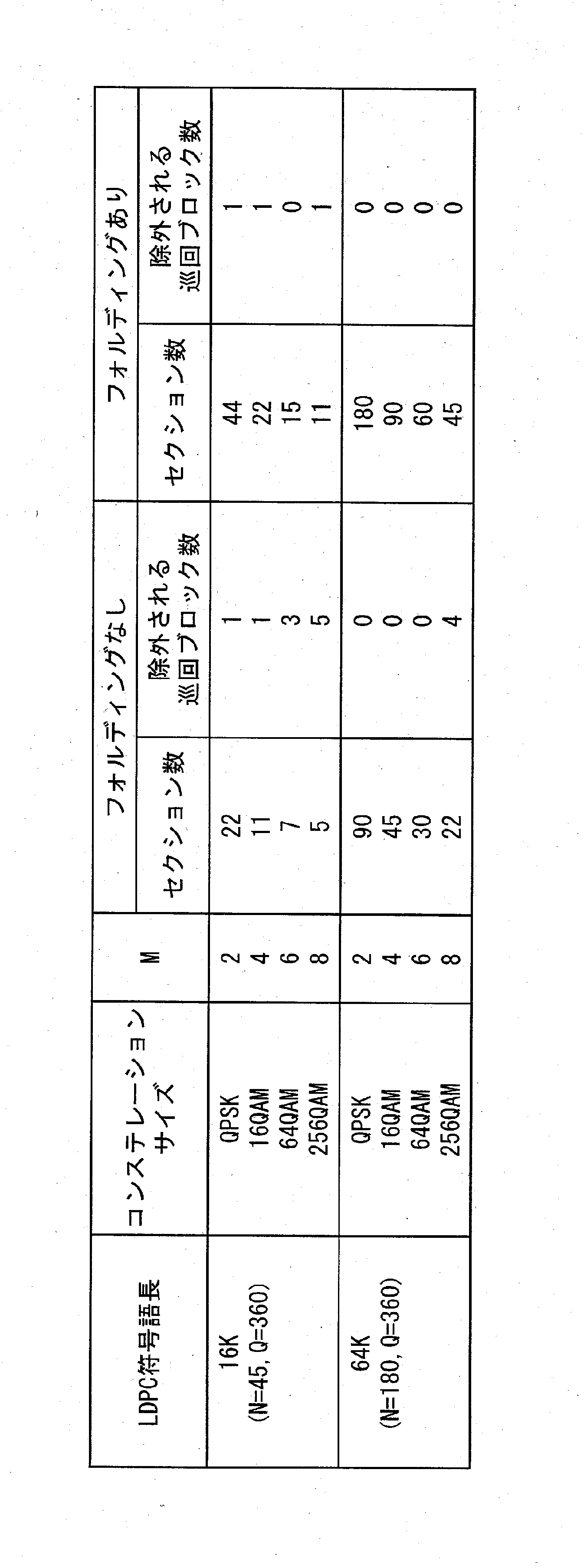
各コンステレーション語のM個のビットが、LDPC符号語のM/F個の異なる巡回ブロックにマッピングされる。これは、LDPC符号語のM/F個の異なる巡回ブロックからF個のビットずつコンステレーション語にマッピングする、ことと等価である。この概要を図31(a)に示す。 (Condition 1A)
The M bits of each constellation word are mapped to M / F different cyclic blocks of the LDPC codeword. This is equivalent to mapping to constellation words of F bits from M / F different cyclic blocks of the LDPC code word. An outline of this is shown in FIG.
M/F個の巡回ブロックにマッピングされるすべてのコンステレーション語が、当該M/F個の巡回ブロックのみにマッピングされる。これは、QビットからなるM/F個の異なる巡回ブロックのM×Q/F個のビットの全ては、Q/F個のコンステレーション語にのみマッピングされる、ことと等価である。この概要を図31(b)に示す。 (Condition 2A)
All constellation words mapped to M / F cyclic blocks are mapped to only the M / F cyclic blocks. This is equivalent to that all of the M × Q / F bits of M / F different cyclic blocks consisting of Q bits are mapped to only Q / F constellation words. An outline of this is shown in FIG.
以下、上記の条件1A、条件2Aを満たすビットインターリーバ(並列ビットインターリーバ)の詳細について説明する。なお、以下において、実質的に同じ処理内容、および、同じ処理内容を行う構成ユニットには同じ符号を付す。 «Embodiment (Part 2)»
The details of the bit interleaver (parallel bit interleaver) satisfying the above conditions 1A and 2A are described below. In the following, the same reference numerals are given to constituent units that perform substantially the same processing content and the same processing content.
以下、NがMの倍数ではなく、フォルディングを行う場合のインターリーバの一例について記載する。 «Embodiment (3)»
Hereinafter, an example of the interleaver in the case where folding is performed instead of N being a multiple of M will be described.
以下、表3で説明したDVB-T2規格で用いられるLDPC符号に対する、セクションパーミュテーションの具体例について説明する。
(例1A)N=45,Q=360,M=4,フォルディングなし(F=1)の場合
図44(a)は、N=45,Q=360,M=4でフォルディングなし(F=1)の場合の、セクションパーミュテーションの構造を示す図である。 Note that, as an example of an interleaver in which N is not a multiple of M and folding is not performed, a configuration in which the
A specific example of section permutation for an LDPC code used in the DVB-T2 standard described in Table 3 will be described below.
(Example 1A) In the case of N = 45, Q = 360, M = 4, no folding (F = 1) In FIG. 44 (a), no folding is performed with N = 45, Q = 360, M = 4 (F It is a figure which shows the structure of section permutation in the case of = 1).
(例1B)N=45,Q=360,M=4でフォルディングあり(F=2)の場合
図44(b)は、N=45,Q=360,M=4でフォルディングあり(F=2)の場合の、セクションパーミュテーションの構造を示す図である。 Note that the bits of
(Example 1B) In the case of folding with N = 45, Q = 360, M = 4 (F = 2), folding is performed with N = 45, Q = 360, M = 4 (F It is a figure which shows the structure of section permutation in the case of = 2).
図45(a)は、N=45,Q=360,M=6でフォルディングなし(F=1)の場合の、セクションパーミュテーションの構造を示す図である。 (Example 2A) In the case of N = 45, Q = 360, M = 6 and no folding (F = 1) In FIG. 45 (a), N = 45, Q = 360, M = 6 and no folding (F It is a figure which shows the structure of section permutation in the case of = 1).
図45(b)は、N=45,Q=360,M=6でフォルディングあり(F=2)の場合の、セクションパーミュテーションの構造を示す図である。 (Example 2B) In the case of folding with N = 45, Q = 360, M = 6 (F = 2) In FIG. 45 (b), there is folding with N = 45, Q = 360, M = 6 (F) It is a figure which shows the structure of section permutation in the case of = 2).
ここまで、効率的なビットインターリーブ方法について説明してきた。ところで、LDPC復号処理における無効検査ノードの存在は誤り訂正能力を低下させる可能性がある。発明者らは、上記ビットインターリーブ方法において、無効検査ノードの発生を抑制する方法について更なる知見を得た。以下、無効検査ノードがどのように発生するか、そして、これをどのように解消するかを説明する。
無効検査ノードは、同じ検査ノードにつながる2以上のLDPCの変数ノードが、同じコンステレーションからマッピングされる場合に発生する。仮に、コンステレーションが深い歪の影響を受けている場合、コンステレーションデマッパの出力である関連するLLR値は、極小または0になる。
仮に、2以上の変数ノードが、同じ検査ノードに連結しており、当該検査ノードのLLR値が0あるいは非常に小さい値である場合、この検査ノードを誤り訂正処理に使用することができなくなるので、少なくとも、第1のLDPC復号の反復処理では、結果的に、値の収束が遅くなる。このような検査ノードを、無効検査ノードと呼称する。
以下においては、どのような場合に、そのような無効検査ノードが発生するのかを、具体例を示しながら説明する。図5に示す、パリティチェック行列によって定義されるLDPC符号の、図5の上から3つ目の巡回ブロックの検査ノード(検査ノードCN17~CN24を参照のこと)を考えてみる。図46においては、パリティ検査ノード17~24に連結されている変数ノードがハイライトされている。即ち、検査ノードと変数ノードとが連結されている部分のみ黒四角で表現している。
このコネクションは、並列構造と巡回パーミュテーションとがより明瞭に理解できるように、図47に示すように記載することができる。8つの検査ノードそれぞれは、巡回パーミュテーションを通して、8つの変数ノードに接続される。ここで、巡回パーミュテーションは、パリティチェック行列の巡回シフト対数に関連する。例えば、図47において、3番目の巡回ブロック(QB3)の各ビットは、検査ノードに2回連結されている。図47においては、最初の検査ノード(CN17参照)と変数ノードとのコネクションがハイライト(太線で記載)されている。なお、このハイライトは、単に検査ノード17と変数ノードとのコネクションをわかりやすくするためのものであり、検査ノード17に特別な意味があるわけではない。 Embodiment (Part 4)
So far, efficient bit interleaving methods have been described. By the way, the presence of invalid check nodes in the LDPC decoding process may reduce the error correction capability. The inventors obtained further knowledge about a method of suppressing the occurrence of invalid check nodes in the above bit interleaving method. The following describes how invalid check nodes occur and how to resolve them.
An invalid check node occurs when two or more LDPC variable nodes connected to the same check node are mapped from the same constellation. If the constellation is subject to deep distortion, then the associated LLR value, which is the output of the constellation demapper, will be either minimal or zero.
If two or more variable nodes are linked to the same check node and the LLR value of the check node is 0 or a very small value, this check node can not be used for error correction processing. As a result, at least the iterative process of the first LDPC decoding results in slower convergence of values. Such check nodes are called invalid check nodes.
In the following, it will be described in what case such an invalid check node is generated while showing a specific example. Consider the check node (see check nodes CN17 to CN24) of the third top cyclic block in FIG. 5 of the LDPC code defined by the parity check matrix shown in FIG. In FIG. 46, variable nodes connected to parity check nodes 17-24 are highlighted. That is, only the part where the check node and the variable node are connected is represented by a black square.
This connection can be described as shown in FIG. 47 so that the parallel structure and cyclic permutation can be understood more clearly. Each of the eight check nodes is connected to eight variable nodes through cyclic permutation. Here, cyclic permutation is associated with cyclic shift logarithms of the parity check matrix. For example, in FIG. 47, each bit of the third cyclic block (QB3) is linked twice to the check node. In FIG. 47, the connection between the first check node (see CN 17) and the variable node is highlighted (indicated by thick lines). This highlight is merely to make the connection between the
検査ノード17~24に接続される8つの巡回ブロックについて、図48(a)~図48(h)は、マッピングの1つの見方を示している。図48(a)~図48(h)の各図面は、各検査ノード17~24に連結している変数ノードをハイライトしている。図48(a)~図48(h)それぞれにおいて、一つの四角は、各巡回ブロックの各変数ノードを示しており、検査ノードに連結している変数ノードは黒四角で示している。また、図47において、検査ノード17と変数ノードとのコネクションをハイライトしているが、図48(a)においても同様の連結関係をもっており、図48(a)と図47においてハイライトした内容とが対応していることがわかる。
以下では、無効検査ノードが発生する場合の2つの事例を示す。なお、ここに示すのは、一例である。
図49(a)~図49(h)は、第1の事例を示している。図49(a)~図49(h)では、図48(a)~図48(h)に示したマッピングを基に、16QAMのコンステレーションに、フォルディング係数Fを2として、QB14とQB15とがマッピングされている例を示している。図49(a)~図49(h)の太線で囲われた4つの四角が1つのコンステレーションに対応する。図49(a)~図49(h)の場合、歪(フェージング)の影響を深く受けたコンステレーション各々は、2つの検査ノードを無効にしてしまう。歪の影響を受けた各コンステレーションに応じて、無効となる検査ノードは、以下の通りである。
・C1が歪の影響を受けた場合:検査ノード17、18(図49(a)、(b)参照)
・C2が歪の影響を受けた場合:検査ノード19、20(図49(c)、(d)参照)
・C3が歪の影響を受けた場合:検査ノード21、22(図49(e)、(f)参照)
・C4が歪の影響を受けた場合:検査ノード23、24(図49(g)、(h)参照)
図50(a)~図50(h)は、第2の事例を示している。図50(a)~図50(h)では、図48(a)~図48(h)に示したマッピングを基に、16QAMのコンステレーションに、フォルディング係数Fを2として、QB4とQB5とがマッピングされている例を示している。図50(a)~図50(h)の太線で囲われた4つの四角が1つのコンステレーションに対応する。図50(a)~図50(h)の場合、歪(フェージング)の影響を深く受けたコンステレーション各々は、1つの検査ノードを無効にしてしまう。歪の影響を受けた各コンステレーションに応じて、無効となる検査ノードは、以下の通りである。
・C1が歪の影響を受けた場合:検査ノード21(図50(e)参照)
・C2が歪の影響を受けた場合:検査ノード23(図50(g)参照)
・C3が歪の影響を受けた場合:検査ノード17(図50(a)参照)
・C4が歪の影響を受けた場合:検査ノード19(図50(c)参照)
無効検査ノードの発生は、同じ検査ノードに連結されている複数の変数ノードを同じコンステレーションにマッピングすることを避けることで抑制できる。これは、並列ビットインターリーブにおいては、巡回ブロック内のビットに対して更なるパーミュテーションを施すことで、実現できる。この無効検査ノードの発生を抑制するためのパーミュテーションを、以降、巡回ブロック内パーミュテーションと呼称する。また、巡回ブロック内パーミュテーションは、基本的に適用する巡回ブロックに応じて異なるものとなる。
巡回ブロック内パーミュテーションは、1以上の巡回シフトにより実現すると構成の実現が容易である。1回だけの巡回シフトの場合、LDPCデコーダに構成された(再構成可能な)ローテータと逆ローテータを再利用することができ、これにより、回路の複雑度を抑制することができる。図51(a)および図51(b)は、それぞれ、Q=8とした場合であって、巡回ブロックについて1回シフトおよび2回シフトを実行する巡回ブロック内インターリーバの構成を示している。図51(a)および図51(b)に示すように、当該巡回ブロック内インターリーバ(5100A、5100B)は、各巡回ブロックに対して実行するシフトのシフト値を保持するテーブルB(5101A、5101B)と、1又は2の再構成可能なローテータ(5102A、5102B、5103B)からなる。巡回ブロック内インターリーバは(5100A、5100B)、どの巡回ブロックが処理対象であるかを示す巡回ブロックインデックスの入力を受け付けて、テーブルB(5101A、5101B)に示される巡回ブロックに対応するシフト値を特定し、当該シフト値をローテータに設定する。ローテータ(5102A、5102B、5103B)は、入力された巡回ブロックの各ビットを、シフト値で指定された値だけ巡回シフトさせて、シフト後のビット列(巡回ブロック内パーミュテーションが施された巡回ブロック)を出力する。巡回ブロック内インターリーバは、図21(b)や図24に示す巡回ブロック内パーミュテーションに相当する。なお、ここでテーブルB(5101A、5101B)に示されるシフト値は、ビット列の右方向に、検査ノードに連結している変数ノードが同じコンステレーションにマッピングされることを回避できる値が記憶されているものとする。
図49(a)~図49(h)および図50(a)~図50(h)を参照すると、これらの場合では、シフト値を以下のように設定することで、無効検査ノードの発生を抑制することができる。即ち、図49(a)~図49(h)それぞれについて、QB14に対して、シフト値を2に設定し、右方向に2巡回シフトさせればよい。また、図50(a)~図50(h)のQB4に対して、シフト値を3に設定し、右方向に3巡回シフトさせればよい。このような巡回シフトを、図49(a)~図49(h)および図50(a)~図50(h)にそれぞれ施した結果を、図52(a)~図52(h)および図53(a)~図53(h)に示す。なお、ここでは、実現が容易な例として、図50(a)~図50(h)のQB4全てに対して右方向に3ビット巡回シフトさせる構成を示しているが、図50(b)、図50(d)、図50(f)、図50(h)については、元々検査ノードに連結する変数ノードが異なるコンステレーションにマッピングされているため、巡回ブロック内パーミュテーションを施さなくともよい。
なお、巡回シフトが必要ない巡回ブロックが入力された場合には、シフト値としては、0が設定され、巡回シフトされることなく入力されたビット列がそのまま出力される。
したがって、LDPC符号における無効検査ノードの数は、各巡回ブロックに対して、適切なパーミュテーションを施すことで、最小限に抑制することが可能である。当然に、巡回ブロック内パーミュテーションは、LDPC符号が変更される度―例えば、採用している符号のPCMが変更された場合など―に、最適化する必要がある。この巡回ブロック内パーミュテーションを実現するにあたって、予め定められた複数のPCMからなるPCMの(限定された)セット(種別)の各PCMに応じた最適なパーミュテーション方法(あるいはシフト値などのパラメータ。当該パラメータは、実質的にパーミュテーション手法と同義である)を予め記憶しておくと有効である。上述の図51(a)におけるテーブルBの保持が、このパーミュテーション方法の記憶に該当する。これによって、例えば、符号化率などが変更されてPCMが変更された場合に、適切なパラメータを有するセットを選択することで、最適なパーミュテーション手法に変更できる。なお、PCMあるいは予め定められたPCMのセットそれぞれに対して最適な巡回ブロック内パーミュテーションは、既知の最適化処理、例えば、総当たり攻撃(brute force)、焼きなまし法(simulated annealing)、モンテカルロ法(Monte-Carlo)などにより導出することができる。
図54は、図24と同様に、フォルディング係数を2に設定した場合の並列ビットインターリーバ5400における巡回ブロック内パーミュテーション5410の機能構成を示す概念図である。動作内容については、図54と図24との差異は、フォルディング係数を4から2にしただけで、セクションパーミュテーションが2巡回ブロック分で実行される以外は、図24の場合と同様であるので、説明を割愛する。また、受信については、この図54に示される各矢印が逆方向になり、それぞれのユニットが実行される処理が送信側で実行される内容とは逆の処理が実行されるだけであるので、詳細な説明を割愛する。
図55は、本実施の形態(その4)に係るQ=8、M=4、F=2とした場合のBICMエンコーダの一実装例を示すブロック図である。 As described above, FIGS. 46 and 47 correspond to each other. For example, in FIG. 46, the check node 17 (
For the eight cyclic blocks connected to the
In the following, two cases are shown in which an invalid check node occurs. In addition, what is shown here is an example.
FIGS. 49 (a) to 49 (h) show the first case. In FIGS. 49 (a) to 49 (h), based on the mapping shown in FIGS. 48 (a) to 48 (h), with a folding coefficient F of 2 in the 16 QAM constellation, QB14 and QB15 and Shows an example where is mapped. Four squares surrounded by thick lines in FIGS. 49 (a) to 49 (h) correspond to one constellation. In the case of FIGS. 49 (a) to 49 (h), each of the constellations deeply affected by distortion (fading) invalidates the two check nodes. The check nodes that become invalid according to each constellation affected by distortion are as follows.
When C1 is affected by distortion: check
When C2 is affected by distortion: check nodes 19 and 20 (see FIGS. 49 (c) and (d))
When C3 is affected by distortion: check nodes 21 and 22 (see FIGS. 49 (e) and (f))
When C4 is affected by strain: check nodes 23, 24 (see FIGS. 49 (g) and (h))
FIGS. 50 (a) to 50 (h) show a second case. In FIG. 50 (a) to FIG. 50 (h), based on the mapping shown in FIG. 48 (a) to FIG. 48 (h), with a folding coefficient F of 2 in the 16 QAM constellation, QB4 and QB5 and Shows an example where is mapped. Four squares surrounded by thick lines in FIGS. 50 (a) to 50 (h) correspond to one constellation. In the case of FIGS. 50 (a) to 50 (h), each constellation deeply affected by distortion (fading) invalidates one check node. The check nodes that become invalid according to each constellation affected by distortion are as follows.
When C1 is affected by distortion: check node 21 (see FIG. 50 (e))
When C2 is affected by distortion: check node 23 (see FIG. 50 (g))
When C3 is affected by distortion: check node 17 (see FIG. 50 (a))
When C4 is affected by distortion: check node 19 (see FIG. 50 (c))
The occurrence of invalid check nodes can be suppressed by avoiding mapping of multiple variable nodes linked to the same check node to the same constellation. This can be realized in parallel bit interleaving by performing additional permutation on the bits in the cyclic block. Hereinafter, permutation for suppressing the occurrence of invalid check nodes is referred to as intra-cyclic block permutation. Also, the intra-cyclic block permutation basically differs depending on the cyclic block to be applied.
The intra-cyclic block permutation is easy to implement if implemented by one or more cyclic shifts. In the case of only one cyclic shift, it is possible to reuse the (reconfigurable) rotator and the derotator configured in the LDPC decoder, thereby reducing the complexity of the circuit. FIGS. 51 (a) and 51 (b) respectively show the configuration of the intra-rotary block interleaver that performs one shift and two shifts for the cyclic block, where Q = 8. As shown in FIGS. 51 (a) and 51 (b), the intra-cyclic-block interleaver (5100A, 5100B) holds the shift value of the shift to be performed for each cyclic block B (5101A, 5101B). And one or two reconfigurable rotators (5102A, 5102B, 5103B). The intra-cyclic block interleaver (5100A, 5100B) receives the input of the cyclic block index indicating which cyclic block is to be processed, and shifts the shift value corresponding to the cyclic block shown in Table B (5101A, 5101B) Identify and set the shift value as a rotator. The rotator (5102A, 5102B, 5103B) cyclically shifts each bit of the input cyclic block by the value designated by the shift value, and shifts the bit string (cyclic block subjected to permutation within cyclic block) Output). The intra-cyclic block interleaver corresponds to intra-cyclic block permutation shown in FIG. 21 (b) and FIG. Here, the shift values shown in the table B (5101A, 5101B) are stored in the right direction of the bit string so that the variable nodes connected to the check node can be prevented from being mapped to the same constellation. It is assumed that
Referring to FIGS. 49 (a) to 49 (h) and FIGS. 50 (a) to 50 (h), in these cases, generation of invalid check nodes can be performed by setting the shift value as follows. It can be suppressed. That is, for each of FIGS. 49 (a) to 49 (h), the shift value may be set to 2 for
When a cyclic block that does not require cyclic shift is input, 0 is set as the shift value, and the input bit string is output as it is without cyclic shift.
Therefore, the number of invalid check nodes in the LDPC code can be minimized by applying appropriate permutations to each cyclic block. Naturally, the intra-cyclic block permutation needs to be optimized each time the LDPC code is changed—for example, when the PCM of the adopted code is changed. In order to realize the permutation within the cyclic block, an optimum permutation method (or shift value, etc.) according to each PCM of (a limited) set (type) of PCMs composed of a plurality of PCMs determined in advance. Parameters: It is effective to store in advance the parameters that are substantially equivalent to permutation methods. The holding of the table B in FIG. 51 (a) described above corresponds to the storage of this permutation method. Thereby, for example, when the coding rate or the like is changed and the PCM is changed, it is possible to change to the optimum permutation method by selecting a set having appropriate parameters. Note that the optimum intra-cyclic block permutation for each PCM or a predetermined set of PCM is a known optimization process such as brute force, simulated annealing, Monte Carlo method (Monte-Carlo) or the like.
FIG. 54 is a conceptual diagram showing a functional configuration of
FIG. 55 is a block diagram showing an implementation example of a BICM encoder when Q = 8, M = 4, and F = 2 according to the present embodiment (part 4).
図56は、本実施の形態(その4)に係るQ=8、M=4、F=2とした場合の反復BICMデコーダの一実装例を示すブロック図である。 The rotator (interleaver B) 5533 cyclically shifts the input bit string in the right direction by the shift value according to the notified shift value, and outputs the result to the
FIG. 56 is a block diagram showing an implementation example of the iterative BICM decoder when Q = 8, M = 4, and F = 2 according to the present embodiment (part 4).
≪補足1≫
本発明は上記の実施の形態で説明した内容に限定されず、本発明の目的とそれに関連又は付随する目的を達成するためのいかなる形態においても実施可能であり、例えば、以下であってもよい。 By providing the above configuration, the BICM encoder can realize permutation within a cyclic block with a simple configuration, and can avoid that a plurality of variable nodes linked to an inspection node are mapped to the same constellation. This can reduce the possibility that the check node will be an invalid check node that can not be used for error correction.
«
The present invention is not limited to the contents described in the above embodiment, but can be practiced in any form for achieving the object of the present invention and the objects related to or associated with it, for example, the following may be possible. .
本発明に係るインターリーブ方法、インターリーバ、デインターリーブ方法、デインターリーバ、およびデコーダとその効果について説明する。 «
An interleaving method, an interleaver, a deinterleaving method, a deinterleaver, and a decoder according to the present invention and their effects will be described.
本発明の一態様である第2のビットインターリーブ方法は、第1のビットインターリーブ方法において、前記巡回ブロック内パーミュテーションは、QC‐LDPC符号の共通の検査ノードにつながる符号語のビットが、それぞれ異なるコンステレーション語にマッピングされるように行われる。 According to these, in addition to enabling implementation of bit interleaving processing with high parallelism, reduction in circuit area and power consumption is achieved. Also, by performing intra-cyclic block permutation, it is possible to reduce the possibility that the check node will become an invalid check node that can not be used for error correction on the receiving side.
A second bit interleaving method according to one aspect of the present invention is the first bit interleaving method, wherein in the intra-cyclic block permutation, bits of codewords leading to a common check node of the QC-LDPC code are respectively It is done to be mapped to different constellation words.
本発明の一態様である第3のビットインターリーブ方法は、第2のビットインターリーブ方法において、前記巡回ブロックに対して施される巡回ブロック内パーミュテーションの少なくとも一つは、少なくとも巡回ブロックを構成するビット列のサブセットに対して、巡回シフトさせることである。 This can ensure that the check node can reduce the possibility of becoming an invalid check node that can not be used for error correction on the receiving side.
A third bit interleaving method according to one aspect of the present invention is the second bit interleaving method, wherein at least one of intra cyclic block permutations applied to the cyclic block constitutes at least a cyclic block. A cyclic shift is performed on a subset of bit strings.
本発明の一態様である第4のビットインターリーブ方法は、第1のビットインターリーブ方法において、更に、セクションを構成するQ×M/Fビットを、M/F行Q列の行列に行方向で書き込み、列方向で読み出すことで実現されるカラム‐ロウパーミュテーションを、各セクションを構成するQ×M/Fビットに対して施すカラム‐ロウパーミュテーションステップを含む。 According to this, in-cyclic block permutation can be realized with a simple configuration called cyclic shift.
The fourth bit interleaving method according to one aspect of the present invention is the first bit interleaving method further including writing Q × M / F bits constituting a section in a matrix of M / F rows and Q columns. And column-row permutation steps in which column-row permutation realized by reading in the column direction is applied to Q × M / F bits constituting each section.
本発明の一態様である第5のビットインターリーブ方法は、第1のビットインターリーブ方法において、更に、各巡回ブロックに対して、通信システムにおいて採用されている特定のQC-LDPC符号に応じて決定される巡回ブロック内パーミュテーション方法であって、予め定めた複数の巡回ブロック内パーミュテーション方法の中から1つの巡回ブロック内パーミュテーション方法を選択する選択ステップを含む。 In a fourth bit interleaver according to one aspect of the present invention, in the first bit interleaver, Q × M / F bits constituting a section are further arrayed in a matrix of M / F rows and Q columns. And a column-row permutation unit which performs column-row permutation realized by writing in the column direction and reading in the column direction with respect to Q × M / F bits constituting each section.
The fifth bit interleaving method according to one aspect of the present invention is further determined in the first bit interleaving method according to a specific QC-LDPC code employed in the communication system for each cyclic block. The intra-cyclic block permutation method includes a selection step of selecting one intra-cyclic block permutation method from among a plurality of predetermined intra-cyclic block permutation methods.
本発明の一態様である第1のビットデインターリーブ方法は、QC‐LDPC符号の通信システムにおけるビットストリームのビットデインターリーブ方法であって、N・Qビットから成るビット列を受信する受信ステップと、受信した前記ビット列に対して、QCLDPC符号の符号語を復元するために、請求項1記載のビットインターリーブ方法と逆手順の処理を施す逆ビットパーミュテーションステップとを含むことを特徴とする。 In this way, it is possible to uniquely specify the cyclic block intra-permutation method determined according to the PCM to realize encoding.
A first bit de-interleaving method according to an aspect of the present invention is a bit de-interleaving method of a bit stream in a communication system of QC-LDPC code, which comprises the steps of: receiving a bit string consisting of N · Q bits; It is characterized by including reverse bit permutation step of performing the processing of the bit interleaving method and reverse procedure according to
2010A ビットパーミュテーションユニット
2021A フォルディングセクションパーミュテーションユニット
2131A、2132A カラム‐ロウパーミュテーションユニット
2500A トランスミッタ
2510 LDPCエンコーダ
2520A ビットインターリーバ
2530 コンステレーションマッパ
2700A、2800A レシーバ
2710 コンステレーションデマッパ
2720A ビットデインターリーバ
2730 LDPCデコーダ
2740 減算ユニット
2750A ビットインターリーバ
5410 巡回ブロック内パーミュテーション
Claims (14)
- 疑似巡回低密度パリティチェック符号を用いる通信システムにおけるビットインターリーブ方法であって、
それぞれがQ個のビットからなるN個の巡回ブロックで構成される前記疑似巡回低密度パリティチェック符号の符号語を受信する受信ステップと、
前記符号語に対して当該符号語のビットの並び順を換えるビットパーミュテーション処理を施すビットパーミュテーションステップと、
ビットパーミュテーション処理が施された符号語を、それぞれM個のビットからなり、それぞれが2M個の所定のコンステレーションポイントのいずれか1つを示す複数のコンステレーション語に分割する分割ステップと、
前記巡回ブロックに対して当該巡回ブロックのビットの並び順を換える巡回ブロック内パーミュテーション処理を施す巡回ブロック内パーミュテーションステップとを含み、
前記分割ステップは、前記ビットパーミュテーション処理が施された符号語を、それぞれM/F(Fは正の整数)個の巡回ブロックからなるF×N/M個のセクションに分割した上で、各コンステレーション語がいずれか1つのセクションに関連付けられるように、コンステレーション語に分割し、
前記ビットパーミュテーション処理は、各コンステレーション語が、関連付けられている前記セクション中のM/F個の前記パーミュテーション処理後の巡回ブロックからF個ずつ抽出したビットから構成されるように施される
ことを特徴とするビットインターリーブ方法。 A bit interleaving method in a communication system using a pseudo cyclic low density parity check code, comprising:
Receiving the codewords of the pseudo-cyclic low density parity check code consisting of N cyclic blocks each consisting of Q bits;
A bit permutation step of performing bit permutation processing for changing the arrangement order of bits of the codeword to the codeword;
A division step of dividing a codeword subjected to bit permutation processing into a plurality of constellation words each consisting of M bits and each indicating any one of 2 M predetermined constellation points ,
And performing an intra-cyclic block permutation step of performing an intra-cyclic block permutation process for changing the order of bits of the cyclic block to the cyclic block,
The dividing step divides the bit permutation-processed code word into F × N / M sections each consisting of M / F (F is a positive integer) cyclic blocks, and Divide into constellation words so that each constellation word is associated with any one section,
The bit permutation process is performed such that each constellation word is composed of F extracted bits from the M / F cyclic blocks after the permutation process in the associated section. A bit interleaving method characterized in that - 前記巡回ブロック内パーミュテーションは、QC‐LDPC符号の共通の検査ノードにつながる符号語のビットが、それぞれ異なるコンステレーション語にマッピングされるように行われる
ことを特徴とする請求項1記載のビットインターリーブ方法。 The bit according to claim 1, wherein the intra-cyclic block permutation is performed such that bits of codewords leading to a common check node of the QC-LDPC code are mapped to different constellation words. Interleaving method. - 前記巡回ブロックに対して施される巡回ブロック内パーミュテーションの少なくとも一つは、少なくとも巡回ブロックを構成するビット列のサブセットに対して、巡回シフトさせることである
ことを特徴とする請求項2記載のビットインターリーブ方法。 The at least one subset of intra-cyclic block permutation applied to the cyclic block is to cyclically shift at least a subset of bit sequences constituting the cyclic block. Bit interleaving method. - 前記ビットインターリーブ方法は、更に、セクションを構成するQ×M/Fビットを、M/F行Q列の行列に行方向で書き込み、列方向で読み出すことで実現されるカラム‐ロウパーミュテーションを、各セクションを構成するQ×M/Fビットに対して施すカラム‐ロウパーミュテーションステップを含む
ことを特徴とする請求項1記載のビットインターリーブ方法。 The bit interleaving method further implements column-row permutation realized by writing Q × M / F bits constituting a section in the row direction in the matrix of M / F rows and Q columns and reading out in the column direction. The bit interleaving method according to claim 1, further comprising a column-row permutation step applied to Q × M / F bits constituting each section. - 前記ビットインターリーブ方法は、更に、各巡回ブロックに対して、通信システムにおいて採用されている特定のQC-LDPC符号に応じて決定される巡回ブロック内パーミュテーション方法であって、予め定めた複数の巡回ブロック内パーミュテーション方法の中から1つの巡回ブロック内パーミュテーション方法を選択する選択ステップを含む
ことを特徴とする請求項1記載のビットインターリーブ方法。 The bit interleaving method is a plurality of predetermined intra-cyclic block permutation methods determined according to a specific QC-LDPC code employed in the communication system for each cyclic block. The bit interleaving method according to claim 1, further comprising a selection step of selecting one in-recirculation block permutation method from the in-recirculation block permutation method. - QC‐LDPC符号の通信システムにおけるビットストリームのビットデインターリーブ方法であって、
N・Qビットから成るビット列を受信する受信ステップと、
受信した前記ビット列に対して、QCLDPC符号の符号語を復元するために、請求項1記載のビットインターリーブ方法と逆手順の処理を施す逆ビットパーミュテーションステップとを含む
ことを特徴とするビットデインターリーブ方法。 A bit de-interleaving method for bit stream in a communication system of QC-LDPC code, comprising:
A receiving step of receiving a bit sequence consisting of N · Q bits;
A bit demutation step including the bit interleaving method according to claim 1 and a reverse bit permutation step of performing reverse processing in order to restore the codeword of the QCLDPC code to the received bit string. Interleaving method. - 疑似巡回低密度パリティチェック符号を用いる通信システムのためのビットインターリーバであって、
それぞれがQ個のビットからなるN個の巡回ブロックで構成される前記疑似巡回低密度パリティチェック符号の符号語を受信し、前記符号語に対して当該符号語のビットの並び順を換えるビットパーミュテーション処理を施すビットパーミュテーション部と、
ビットパーミュテーション処理が施された符号語を、それぞれM個のビットからなり、それぞれが2M個の所定のコンステレーションポイントのいずれか1つを示す複数のコンステレーション語に分割する分割部と、
前記巡回ブロックに対して当該巡回ブロックのビットの並び順を換える巡回ブロック内パーミュテーション処理を施す巡回ブロック内パーミュテーション部とを含み、
前記分割部は、前記ビットパーミュテーション処理が施された符号語を、それぞれM/F(Fは正の整数)個の巡回ブロックからなるF×N/M個のセクションに分割した上で、各コンステレーション語がいずれか1つのセクションに関連付けられるように、コンステレーション語に分割し、
前記ビットパーミュテーション処理は、各コンステレーション語が、関連付けられている前記セクション中のM/F個の前記パーミュテーション処理後の巡回ブロックからF個ずつ抽出したビットから構成されるように施される
ことを特徴とするビットインターリーバ。 A bit interleaver for a communication system using a pseudo-cyclic low density parity check code,
A bit per received a codeword of the pseudo cyclic low density parity check code consisting of N cyclic blocks each consisting of Q bits, and changing the order of bits of the codeword with respect to the codeword. A bit permutation unit that performs a mutation process,
A division unit configured to divide a codeword subjected to bit permutation processing into a plurality of constellation words each consisting of M bits and each indicating any one of 2 M predetermined constellation points; ,
An intra-cyclic block permutation unit which performs intra-cyclic block permutation processing for changing the order of bits of the cyclic block to the cyclic block;
The division unit divides the codeword subjected to the bit permutation processing into F × N / M sections each consisting of M / F (F is a positive integer) cyclic blocks, and Divide into constellation words so that each constellation word is associated with any one section,
The bit permutation process is performed such that each constellation word is composed of F extracted bits from the M / F cyclic blocks after the permutation process in the associated section. A bit interleaver characterized in that - 前記巡回ブロック内パーミュテーションは、QC‐LDPC符号の共通の検査ノードにつながる符号語のビットが、それぞれ異なるコンステレーション語にマッピングされるように行われる
ことを特徴とする請求項7記載のビットインターリーバ。 The bit according to claim 7, characterized in that the intra-cyclic block permutation is performed such that bits of codewords leading to a common check node of the QC-LDPC code are mapped to different constellation words. Interleaver. - 前記巡回ブロックに対して施される巡回ブロック内パーミュテーションの少なくとも一つは、少なくとも巡回ブロックを構成するビット列のサブセットに対して、巡回シフトさせることである
ことを特徴とする請求項8記載のビットインターリーバ。 The at least one subset of intra-cyclic block permutation applied to the cyclic block is to cyclically shift at least a subset of bit sequences constituting the cyclic block. Bit interleaver. - 更に、セクションを構成するQ×M/Fビットを、M/F行Q列の行列に行方向で書き込み、列方向で読み出すことで実現されるカラム‐ロウパーミュテーションを、各セクションを構成するQ×M/Fビットに対して施すカラム‐ロウパーミュテーション部を備える
ことを特徴とする請求項7記載のビットインターリーバ。 Furthermore, each section is configured with column-row permutation realized by writing the Q × M / F bits constituting the section in the row direction in the matrix of M / F rows and Q columns and reading out in the column direction The bit interleaver according to claim 7, further comprising a column-row permutation unit to apply to Q × M / F bits. - 更に、各巡回ブロックに対して、通信システムにおいて採用されている特定のQC-LDPC符号に応じて決定される巡回ブロック内パーミュテーション方法であって、予め定めた複数の巡回ブロック内パーミュテーション方法の中から1つの巡回ブロック内パーミュテーション方法を選択する選択部を含む
ことを特徴とする請求項7記載のビットインターリーバ。 Furthermore, for each cyclic block, an intra-cyclic block permutation method determined according to a specific QC-LDPC code employed in the communication system, wherein a plurality of predetermined cyclic intra-block permutations are determined. The bit interleaver according to claim 7, further comprising: a selection unit that selects one intra-cyclic block permutation method from among the methods. - QC‐LDPC符号の通信システムにおけるビットストリームのビットデインターリーバであって、
N・Qビットから成るビット列を受信する受信し、受信した前記ビット列に対して、QCLDPC符号の符号語を復元するために、請求項7記載のビットインターリーバと逆手順のビットパーミュテーション処理を施す逆ビットパーミュテーション部とを含む
ことを特徴とするビットデインターリーバ。 A bit deinterleaver for bit streams in the communication system of QC-LDPC code,
8. A bit permutation process according to the bit interleaver as claimed in claim 7, for receiving a bit string consisting of N · Q bits, and for recovering the codeword of the QCLDPC code for the received bit string. What is claimed is: 1. A bit deinterleaver comprising: a reverse bit permutation unit to be applied. - 疑似巡回低密度パリティチェック符号を用いるビットインターリーブおよび変調システムのためのデコーダであって、
対応するビットが0であるか1であるかの可能性を示すソフトビット列を生成するコンステレーションデマッパと、
クレーム12記載の前記ソフトビット列をデインターリーブするデインターリーバと、
デインターリーブされた前記ソフトビット列をデコードする低密度チェックパリティチェックデコーダと
を備えることを特徴とするデコーダ。 A decoder for a bit interleaving and modulation system using a pseudo-cyclic low density parity check code,
A constellation demapper that generates a soft bit string that indicates whether the corresponding bit is a 0 or a 1;
A deinterleaver that deinterleaves the soft bit sequence according to claim 12;
A low density check parity check decoder for decoding the deinterleaved soft bit sequence. - 前記低密度パリティチェックデコーダの入力と出力との差分を算出する減算器と、
請求項7記載のインターリーバであって、前記差分をコンステレーションデマッパにフィードバックするインターリーバと
を更に備えることを特徴とする請求項13記載のデコーダ。 A subtractor for calculating a difference between an input and an output of the low density parity check decoder;
The interleaver of claim 7, further comprising: an interleaver that feeds back the difference to a constellation demapper.
Priority Applications (16)
| Application Number | Priority Date | Filing Date | Title |
|---|---|---|---|
| CN201280022664.7A CN103636131B (en) | 2011-05-18 | 2012-05-18 | Parallel bit interleaver |
| ES12785728.2T ES2546912T3 (en) | 2011-05-18 | 2012-05-18 | Bit interleaver for a BICM system with QC LDPC codes |
| EP15172086.9A EP2940879B1 (en) | 2011-05-18 | 2012-05-18 | Bit interleaver for a bicm system with qc-ldpc codes |
| EP18185731.9A EP3413469B1 (en) | 2011-05-18 | 2012-05-18 | Bit interleaver for a bicm system with qc-ldpc codes |
| PL12785728T PL2566054T3 (en) | 2011-05-18 | 2012-05-18 | Bit interleaver for a BICM system with QC LDPC codes |
| JP2013515009A JP5719929B2 (en) | 2011-05-18 | 2012-05-18 | Parallel bit interleaver |
| US14/116,632 US20140129895A1 (en) | 2011-05-18 | 2012-05-18 | Parallel bit interleaver |
| EP12785728.2A EP2566054B1 (en) | 2011-05-18 | 2012-05-18 | Bit interleaver for a BICM system with QC LDPC codes |
| US14/804,466 US9319072B2 (en) | 2011-05-18 | 2015-07-21 | Parallel bit interleaver |
| US15/070,290 US9515681B2 (en) | 2011-05-18 | 2016-03-15 | Parallel bit interleaver |
| US15/335,501 US9673838B2 (en) | 2011-05-18 | 2016-10-27 | Parallel bit interleaver |
| US15/581,148 US10097210B2 (en) | 2011-05-18 | 2017-04-28 | Parallel bit interleaver |
| US16/117,625 US10361726B2 (en) | 2011-05-18 | 2018-08-30 | Parallel bit interleaver |
| US16/437,307 US10886946B2 (en) | 2011-05-18 | 2019-06-11 | Parallel bit interleaver |
| US17/102,739 US11362680B2 (en) | 2011-05-18 | 2020-11-24 | Parallel bit interleaver |
| US17/739,465 US20220263523A1 (en) | 2011-05-18 | 2022-05-09 | Parallel bit interleaver |
Applications Claiming Priority (2)
| Application Number | Priority Date | Filing Date | Title |
|---|---|---|---|
| EP11004125.8 | 2011-05-18 | ||
| EP11004125A EP2525496A1 (en) | 2011-05-18 | 2011-05-18 | Bit-interleaved coding and modulation (BICM) with quasi-cyclic LDPC codes |
Related Child Applications (2)
| Application Number | Title | Priority Date | Filing Date |
|---|---|---|---|
| US14/116,632 A-371-Of-International US20140129895A1 (en) | 2011-05-18 | 2012-05-18 | Parallel bit interleaver |
| US14/804,466 Continuation US9319072B2 (en) | 2011-05-18 | 2015-07-21 | Parallel bit interleaver |
Publications (1)
| Publication Number | Publication Date |
|---|---|
| WO2012157286A1 true WO2012157286A1 (en) | 2012-11-22 |
Family
ID=44720328
Family Applications (1)
| Application Number | Title | Priority Date | Filing Date |
|---|---|---|---|
| PCT/JP2012/003272 WO2012157286A1 (en) | 2011-05-18 | 2012-05-18 | Parallel bit interleaver |
Country Status (9)
| Country | Link |
|---|---|
| US (9) | US20140129895A1 (en) |
| EP (4) | EP2525496A1 (en) |
| JP (8) | JP5719929B2 (en) |
| CN (5) | CN107733438B (en) |
| ES (2) | ES2728100T3 (en) |
| HU (1) | HUE025354T2 (en) |
| PL (1) | PL2566054T3 (en) |
| TW (5) | TWI684330B (en) |
| WO (1) | WO2012157286A1 (en) |
Cited By (6)
| Publication number | Priority date | Publication date | Assignee | Title |
|---|---|---|---|---|
| JP2016519857A (en) * | 2013-06-19 | 2016-07-07 | 三菱電機株式会社 | Method and system for modulating data for optical communication |
| WO2016114156A1 (en) * | 2015-01-13 | 2016-07-21 | ソニー株式会社 | Data processing device and data processing method |
| KR20190064556A (en) * | 2014-02-19 | 2019-06-10 | 삼성전자주식회사 | Transmitting apparatus and interleaving method thereof |
| CN110024294A (en) * | 2016-11-21 | 2019-07-16 | 华为技术有限公司 | The generation of Space Coupling quasi-cyclic LDPC code |
| US10425110B2 (en) | 2014-02-19 | 2019-09-24 | Samsung Electronics Co., Ltd. | Transmitting apparatus and interleaving method thereof |
| CN110943746A (en) * | 2014-02-19 | 2020-03-31 | 三星电子株式会社 | Transmitting apparatus and interleaving method thereof |
Families Citing this family (37)
| Publication number | Priority date | Publication date | Assignee | Title |
|---|---|---|---|---|
| DE102010039477A1 (en) * | 2010-08-18 | 2012-02-23 | Robert Bosch Gmbh | Method and device for determining a lifting height of a working machine |
| US9240808B2 (en) * | 2010-09-10 | 2016-01-19 | Trellis Phase Communications, Lp | Methods, apparatus, and systems for coding with constrained interleaving |
| US9362955B2 (en) * | 2010-09-10 | 2016-06-07 | Trellis Phase Communications, Lp | Encoding and decoding using constrained interleaving |
| EP2525498A1 (en) * | 2011-05-18 | 2012-11-21 | Panasonic Corporation | Bit-interleaved coding and modulation (BICM) with quasi-cyclic LDPC codes |
| EP2525496A1 (en) * | 2011-05-18 | 2012-11-21 | Panasonic Corporation | Bit-interleaved coding and modulation (BICM) with quasi-cyclic LDPC codes |
| EP2525495A1 (en) | 2011-05-18 | 2012-11-21 | Panasonic Corporation | Bit-interleaved coding and modulation (BICM) with quasi-cyclic LDPC codes |
| EP2525497A1 (en) | 2011-05-18 | 2012-11-21 | Panasonic Corporation | Bit-interleaved coding and modulation (BICM) with quasi-cyclic LDPC codes |
| EP2552043A1 (en) * | 2011-07-25 | 2013-01-30 | Panasonic Corporation | Spatial multiplexing for bit-interleaved coding and modulation with quasi-cyclic LDPC codes |
| EP2560311A1 (en) * | 2011-08-17 | 2013-02-20 | Panasonic Corporation | Cyclic-block permutations for spatial multiplexing with quasi-cyclic LDPC codes |
| US9094125B2 (en) * | 2012-05-24 | 2015-07-28 | Nec Laboratories America, Inc. | Multidimensional coded-modulation for high-speed optical transport over few-mode fibers |
| US9619317B1 (en) * | 2012-12-18 | 2017-04-11 | Western Digital Technologies, Inc. | Decoder having early decoding termination detection |
| GB2509073B (en) * | 2012-12-19 | 2015-05-20 | Broadcom Corp | Methods and apparatus for error coding |
| US9319250B2 (en) | 2013-03-15 | 2016-04-19 | Jonathan Kanter | Turbo decoding techniques |
| US9608851B2 (en) | 2013-03-15 | 2017-03-28 | Jonathan Kanter | Turbo decoding techniques |
| KR102046343B1 (en) * | 2013-04-18 | 2019-11-19 | 삼성전자주식회사 | Apparatus and method for transmitting signal in a digital image broadcast system |
| EP2890016A1 (en) * | 2013-12-30 | 2015-07-01 | Alcatel Lucent | Ldpc encoder and decoder |
| CN105099615B (en) * | 2014-05-22 | 2020-08-07 | 上海数字电视国家工程研究中心有限公司 | L DPC code word interleaving and mapping method and de-interleaving and de-mapping method |
| KR101792806B1 (en) * | 2014-02-20 | 2017-11-02 | 상하이 내셔널 엔지니어링 리서치 센터 오브 디지털 텔레비전 컴퍼니, 리미티드 | Interleaving and mapping method and deinterleaving and demapping method for ldpc codeword |
| CN111245442B (en) | 2014-03-19 | 2023-06-30 | 三星电子株式会社 | Transmitting apparatus and interleaving method thereof |
| KR101776272B1 (en) * | 2014-03-19 | 2017-09-07 | 삼성전자주식회사 | Transmitting apparatus and interleaving method thereof |
| KR102159242B1 (en) * | 2014-05-21 | 2020-09-24 | 삼성전자주식회사 | Transmitter and signal processing method thereof |
| US9369151B2 (en) * | 2014-09-25 | 2016-06-14 | Ali Misfer ALKATHAMI | Apparatus and method for resource allocation |
| KR102287623B1 (en) * | 2015-02-16 | 2021-08-10 | 한국전자통신연구원 | Bit interleaver for 1024-symbol mapping and low density parity check codeword with 64800 length, 4/15 rate, and method using the same |
| WO2016140513A1 (en) | 2015-03-02 | 2016-09-09 | Samsung Electronics Co., Ltd. | Transmitter and parity permutation method thereof |
| KR102397896B1 (en) * | 2015-05-29 | 2022-05-13 | 삼성전자주식회사 | Receiver and signal processing method thereof |
| WO2016194623A1 (en) * | 2015-06-01 | 2016-12-08 | ソニー株式会社 | Data processing device and data processing method |
| CN108011691B (en) * | 2016-10-27 | 2021-04-06 | 电信科学技术研究院 | Transmission method and device of low-density parity check code |
| CN109474373B (en) * | 2017-09-08 | 2021-01-29 | 华为技术有限公司 | Interleaving method and interleaving apparatus |
| US11003375B2 (en) | 2018-05-15 | 2021-05-11 | Micron Technology, Inc. | Code word format and structure |
| US10831653B2 (en) | 2018-05-15 | 2020-11-10 | Micron Technology, Inc. | Forwarding code word address |
| TWI685217B (en) * | 2018-07-23 | 2020-02-11 | 朱盈宇 | Packet order recognizable correcting code |
| US10505676B1 (en) * | 2018-08-10 | 2019-12-10 | Acacia Communications, Inc. | System, method, and apparatus for interleaving data |
| TWI707231B (en) * | 2018-09-28 | 2020-10-11 | 大陸商深圳大心電子科技有限公司 | Decoder design method and storage controller |
| CN113839738B (en) * | 2020-06-23 | 2023-06-20 | 中国科学院上海高等研究院 | Cross-reading block interleaving processing method and system |
| CN112636767B (en) * | 2020-12-03 | 2023-04-07 | 重庆邮电大学 | Layered semi-parallel LDPC decoder system with single replacement network |
| CN114422315B (en) * | 2022-03-29 | 2022-07-29 | 中山大学 | Ultra-high throughput IFFT/FFT modulation and demodulation method |
| CN115425988B (en) * | 2022-07-29 | 2024-02-09 | 北京融为科技有限公司 | High-speed LDPC full-mode column transformation method |
Citations (2)
| Publication number | Priority date | Publication date | Assignee | Title |
|---|---|---|---|---|
| JP2008125085A (en) * | 2007-11-13 | 2008-05-29 | Matsushita Electric Ind Co Ltd | Modulator and modulation method |
| WO2009116204A1 (en) * | 2008-03-18 | 2009-09-24 | ソニー株式会社 | Data processing device and data processing method |
Family Cites Families (64)
| Publication number | Priority date | Publication date | Assignee | Title |
|---|---|---|---|---|
| US5602875A (en) | 1995-01-13 | 1997-02-11 | Motorola, Inc. | Method and apparatus for encoding and decoding information in a digtial communication system |
| TW324872B (en) * | 1995-01-13 | 1998-01-11 | Motorola Inc | Apparatus for encoding and decoding information in a digital communication system |
| JP3963737B2 (en) | 2002-02-28 | 2007-08-22 | 松下電器産業株式会社 | Multi-carrier signal generation method, radio transmission apparatus, and radio reception apparatus |
| CN1252935C (en) * | 2002-12-13 | 2006-04-19 | 清华大学 | Information source-channel united coding method based on low-density odd-even check coding |
| US7016690B2 (en) | 2003-02-10 | 2006-03-21 | Flarion Technologies, Inc. | Methods and apparatus for updating mobile node location information |
| EP1463255A1 (en) * | 2003-03-25 | 2004-09-29 | Sony United Kingdom Limited | Interleaver for mapping symbols on the carriers of an OFDM system |
| GB2454195A (en) * | 2007-10-30 | 2009-05-06 | Sony Corp | Address generation polynomial and permutation matrix for DVB-T2 16k OFDM sub-carrier mode interleaver |
| US8155178B2 (en) | 2007-10-30 | 2012-04-10 | Sony Corporation | 16k mode interleaver in a digital video broadcasting (DVB) standard |
| CN100483952C (en) * | 2003-04-02 | 2009-04-29 | 高通股份有限公司 | Extracting soft information in a block-coherent communication system |
| US7334181B2 (en) * | 2003-09-04 | 2008-02-19 | The Directv Group, Inc. | Method and system for providing short block length low density parity check (LDPC) codes |
| KR100918763B1 (en) * | 2003-11-14 | 2009-09-24 | 삼성전자주식회사 | Interleaving apparatus and method in a channel coder using a parallel concatenated low density parity check code |
| JP4534128B2 (en) * | 2004-03-05 | 2010-09-01 | ソニー株式会社 | Encoding method and apparatus |
| US7831883B2 (en) * | 2004-04-02 | 2010-11-09 | Nortel Networks Limited | LDPC encoders, decoders, systems and methods |
| US7281192B2 (en) * | 2004-04-05 | 2007-10-09 | Broadcom Corporation | LDPC (Low Density Parity Check) coded signal decoding using parallel and simultaneous bit node and check node processing |
| KR20060097503A (en) * | 2005-03-11 | 2006-09-14 | 삼성전자주식회사 | Channel interleaving/de-interleaving apparatus in a communication system using a low density parity check code and control method thereof |
| KR20080048988A (en) * | 2005-04-15 | 2008-06-03 | 트렐리스웨어 테크놀러지스, 인코포레이티드 | Clash-free irregular-repeat-accumulate code |
| KR100946884B1 (en) * | 2005-07-15 | 2010-03-09 | 삼성전자주식회사 | Channel interleaving/de-interleaving apparatus in a communication system using a low density parity check code and control method thereof |
| US7793190B1 (en) * | 2005-08-10 | 2010-09-07 | Trellisware Technologies, Inc. | Reduced clash GRA interleavers |
| WO2007088870A1 (en) * | 2006-02-02 | 2007-08-09 | Mitsubishi Electric Corporation | Check matrix generating method, encoding method, decoding method, communication device, encoder, and decoder |
| CN101043483A (en) * | 2006-03-20 | 2007-09-26 | 松下电器产业株式会社 | High-order coded modulation method based on low density check code |
| US7971130B2 (en) * | 2006-03-31 | 2011-06-28 | Marvell International Ltd. | Multi-level signal memory with LDPC and interleaving |
| CN100589564C (en) * | 2006-04-18 | 2010-02-10 | 华为技术有限公司 | Channel interleaving method in a kind of hand TV system and system |
| US7830957B2 (en) * | 2006-05-02 | 2010-11-09 | Qualcomm Incorporated | Parallel bit interleaver for a wireless system |
| JP4856605B2 (en) * | 2006-08-31 | 2012-01-18 | パナソニック株式会社 | Encoding method, encoding apparatus, and transmission apparatus |
| CN1917414A (en) * | 2006-09-01 | 2007-02-21 | 华为技术有限公司 | Method and system for implementing interleaving and de-interleaving at second time in physical layer of mobile communication |
| US7783952B2 (en) * | 2006-09-08 | 2010-08-24 | Motorola, Inc. | Method and apparatus for decoding data |
| US7934139B2 (en) * | 2006-12-01 | 2011-04-26 | Lsi Corporation | Parallel LDPC decoder |
| KR101119302B1 (en) * | 2007-04-20 | 2012-03-19 | 재단법인서울대학교산학협력재단 | Apparatus and method for encoding low density parity check codes in a communication system |
| JP4788650B2 (en) * | 2007-04-27 | 2011-10-05 | ソニー株式会社 | LDPC decoding apparatus, decoding method thereof, and program |
| CN101325474B (en) * | 2007-06-12 | 2012-05-09 | 中兴通讯股份有限公司 | Method for encoding channel of mixed automatic request retransmission and modulation mapping of LDPC code |
| US7873897B2 (en) * | 2007-09-17 | 2011-01-18 | Industrial Technology Research Institute | Devices and methods for bit-level coding and decoding of turbo codes |
| ES2407505T3 (en) * | 2007-10-30 | 2013-06-12 | Sony Corporation | Apparatus and method of data processing |
| TWI538415B (en) | 2007-11-26 | 2016-06-11 | Sony Corp | Data processing device and data processing method |
| TWI459724B (en) | 2007-11-26 | 2014-11-01 | Sony Corp | Data processing device and data processing method |
| TWI497920B (en) | 2007-11-26 | 2015-08-21 | Sony Corp | Data processing device and data processing method |
| TWI410055B (en) | 2007-11-26 | 2013-09-21 | Sony Corp | Data processing device, data processing method and program product for performing data processing method on computer |
| JP5325237B2 (en) | 2008-03-03 | 2013-10-23 | ライ・ラディオテレヴィシオーネ・イタリアーナ・ソシエタ・ペル・アチオニ | Bit substitution pattern for LDPC code modulation and QAM constellation |
| ITTO20080472A1 (en) * | 2008-06-16 | 2009-12-17 | Rai Radiotelevisione Italiana Spa | METHOD OF PROCESSING DIGITAL SIGNALS AND TRANSMISSION AND RECEPTION SYSTEM THAT IMPLEMENTS THIS METHOD |
| WO2010024914A1 (en) * | 2008-08-29 | 2010-03-04 | Thomson Licensing | System and method for reusing dvb-s2 ldpc codes in dvb-c2 |
| JP5584219B2 (en) * | 2008-10-03 | 2014-09-03 | トムソン ライセンシング | Method and apparatus for adapting bit interleaver to LDPC code and modulation under AWGN channel conditions using binary erasure surrogate channel |
| CN102349257B (en) * | 2009-01-14 | 2015-02-25 | 汤姆森特许公司 | Method and apparatus for demultiplexer design for multli-edge type Low Density Parity Check coded modulation |
| US8219874B2 (en) * | 2009-02-19 | 2012-07-10 | Nec Laboratories America, Inc. | Multi-dimensional LDPC coded modulation for high-speed optical transmission systems |
| JP5440836B2 (en) * | 2009-03-24 | 2014-03-12 | ソニー株式会社 | Receiving apparatus and method, program, and receiving system |
| US9362955B2 (en) * | 2010-09-10 | 2016-06-07 | Trellis Phase Communications, Lp | Encoding and decoding using constrained interleaving |
| CN102055485A (en) * | 2010-12-24 | 2011-05-11 | 中国人民解放军理工大学 | Quasi-cyclic low-density parity-check (QC-LDPC) code and correcting and linear coding method thereof |
| US8656245B2 (en) * | 2011-04-13 | 2014-02-18 | California Institute Of Technology | Method of error floor mitigation in low-density parity-check codes |
| US8743984B2 (en) * | 2011-04-18 | 2014-06-03 | Nec Laboratories America, Inc. | Multidimensional hybrid modulations for ultra-high-speed optical transport |
| EP2525495A1 (en) * | 2011-05-18 | 2012-11-21 | Panasonic Corporation | Bit-interleaved coding and modulation (BICM) with quasi-cyclic LDPC codes |
| EP2525497A1 (en) * | 2011-05-18 | 2012-11-21 | Panasonic Corporation | Bit-interleaved coding and modulation (BICM) with quasi-cyclic LDPC codes |
| EP2525496A1 (en) * | 2011-05-18 | 2012-11-21 | Panasonic Corporation | Bit-interleaved coding and modulation (BICM) with quasi-cyclic LDPC codes |
| US8874987B2 (en) * | 2011-10-06 | 2014-10-28 | Nec Laboratories America, Inc. | Optimum signal constellation design for high-speed optical transmission |
| US8930789B1 (en) * | 2013-01-23 | 2015-01-06 | Viasat, Inc. | High-speed LDPC decoder |
| US9367387B2 (en) * | 2013-01-24 | 2016-06-14 | Nec Corporation | Rate adaptive irregular QC-LDPC codes from pairwise balanced designs for ultra-high-speed optical transports |
| US9184873B2 (en) * | 2013-03-18 | 2015-11-10 | Nec Laboratories America, Inc. | Ultra-high-speed optical transport based on adaptive LDPC-coded multidimensional spatial-spectral scheme and orthogonal prolate spheroidal wave functions |
| KR101783619B1 (en) * | 2013-11-29 | 2017-10-10 | 엘지전자 주식회사 | Apparatus for transmitting broadcast signals, apparatus for receiving broadcast signals, method for transmitting broadcast signals and method for receiving broadcast signals |
| US9203555B2 (en) * | 2014-02-13 | 2015-12-01 | Nec Laboratories America, Inc. | Optimum signal constellation design and mapping for few-mode fiber based LDPC-coded CO-OFDM |
| EP2947836A1 (en) * | 2014-05-22 | 2015-11-25 | Panasonic Corporation | Cyclic-block permutations for 1D-4096-QAM with quasi-cyclic LDPC codes and code rates 6/15, 7/15, and 8/15 |
| KR102260767B1 (en) * | 2014-05-22 | 2021-06-07 | 한국전자통신연구원 | Bit interleaver for 64-symbol mapping and low density parity check codeword with 16200 length, 3/15 rate, and method using the same |
| US10078540B2 (en) * | 2014-06-13 | 2018-09-18 | Cisco Technology, Inc. | Accurate and fast in-service estimation of input bit error ratio of low density parity check decoders |
| KR102287614B1 (en) * | 2015-02-12 | 2021-08-10 | 한국전자통신연구원 | Bit interleaver for 16-symbol mapping and low density parity check codeword with 64800 length, 2/15 rate, and method using the same |
| WO2016140515A1 (en) * | 2015-03-02 | 2016-09-09 | Samsung Electronics Co., Ltd. | Transmitter and parity permutation method thereof |
| US9692453B2 (en) * | 2015-05-19 | 2017-06-27 | Samsung Electronics Co., Ltd. | Transmitting apparatus and interleaving method thereof |
| EP3602795B1 (en) * | 2017-05-05 | 2024-04-10 | Mediatek Inc. | Generation of parity check matrices from a base graph in dependence on code block size and code rate |
| CN114679185A (en) * | 2017-08-11 | 2022-06-28 | 中兴通讯股份有限公司 | Data coding method and device |
-
2011
- 2011-05-18 EP EP11004125A patent/EP2525496A1/en not_active Withdrawn
-
2012
- 2012-05-18 TW TW107113058A patent/TWI684330B/en active
- 2012-05-18 CN CN201710826271.6A patent/CN107733438B/en active Active
- 2012-05-18 TW TW110106596A patent/TWI780603B/en active
- 2012-05-18 EP EP15172086.9A patent/EP2940879B1/en active Active
- 2012-05-18 JP JP2013515009A patent/JP5719929B2/en active Active
- 2012-05-18 EP EP12785728.2A patent/EP2566054B1/en active Active
- 2012-05-18 CN CN201710826052.8A patent/CN107707262B/en active Active
- 2012-05-18 ES ES15172086T patent/ES2728100T3/en active Active
- 2012-05-18 WO PCT/JP2012/003272 patent/WO2012157286A1/en active Application Filing
- 2012-05-18 TW TW101117769A patent/TWI575885B/en active
- 2012-05-18 CN CN201280022664.7A patent/CN103636131B/en active Active
- 2012-05-18 US US14/116,632 patent/US20140129895A1/en not_active Abandoned
- 2012-05-18 TW TW105141436A patent/TWI625944B/en active
- 2012-05-18 PL PL12785728T patent/PL2566054T3/en unknown
- 2012-05-18 ES ES12785728.2T patent/ES2546912T3/en active Active
- 2012-05-18 EP EP18185731.9A patent/EP3413469B1/en active Active
- 2012-05-18 HU HUE12785728A patent/HUE025354T2/en unknown
- 2012-05-18 CN CN201710826149.9A patent/CN107707332B/en active Active
- 2012-05-18 CN CN201710826176.6A patent/CN107733567B/en active Active
- 2012-05-18 TW TW108146454A patent/TWI721717B/en active
-
2015
- 2015-03-19 JP JP2015056277A patent/JP5876603B2/en active Active
- 2015-07-21 US US14/804,466 patent/US9319072B2/en active Active
-
2016
- 2016-01-20 JP JP2016008440A patent/JP6072944B2/en active Active
- 2016-03-15 US US15/070,290 patent/US9515681B2/en active Active
- 2016-10-27 US US15/335,501 patent/US9673838B2/en active Active
- 2016-12-28 JP JP2016256058A patent/JP6254671B2/en active Active
-
2017
- 2017-04-28 US US15/581,148 patent/US10097210B2/en active Active
- 2017-11-15 JP JP2017219557A patent/JP6430611B2/en active Active
-
2018
- 2018-08-30 US US16/117,625 patent/US10361726B2/en active Active
- 2018-10-29 JP JP2018202754A patent/JP6567154B2/en active Active
-
2019
- 2019-06-11 US US16/437,307 patent/US10886946B2/en active Active
- 2019-07-29 JP JP2019138904A patent/JP6784812B2/en active Active
-
2020
- 2020-10-23 JP JP2020177706A patent/JP6975303B2/en active Active
- 2020-11-24 US US17/102,739 patent/US11362680B2/en active Active
-
2022
- 2022-05-09 US US17/739,465 patent/US20220263523A1/en not_active Abandoned
Patent Citations (2)
| Publication number | Priority date | Publication date | Assignee | Title |
|---|---|---|---|---|
| JP2008125085A (en) * | 2007-11-13 | 2008-05-29 | Matsushita Electric Ind Co Ltd | Modulator and modulation method |
| WO2009116204A1 (en) * | 2008-03-18 | 2009-09-24 | ソニー株式会社 | Data processing device and data processing method |
Non-Patent Citations (2)
| Title |
|---|
| DOUILLARD, C.: "The Bit Interleaved Coded Modulation module for DVB-NGH: Enhanced features for mobile reception", TELECOMMUNICATIONS (ICT), 2012 19TH INTERNATIONAL CONFERENCE, 23 April 2012 (2012-04-23) * |
| See also references of EP2566054A4 * |
Cited By (16)
| Publication number | Priority date | Publication date | Assignee | Title |
|---|---|---|---|---|
| JP2016519857A (en) * | 2013-06-19 | 2016-07-07 | 三菱電機株式会社 | Method and system for modulating data for optical communication |
| KR20210047844A (en) * | 2014-02-19 | 2021-04-30 | 삼성전자주식회사 | Transmitting apparatus and interleaving method thereof |
| KR20220111233A (en) * | 2014-02-19 | 2022-08-09 | 삼성전자주식회사 | Transmitting apparatus and interleaving method thereof |
| US11817881B2 (en) | 2014-02-19 | 2023-11-14 | Samsung Electronics Co., Ltd. | Transmitting apparatus and interleaving method thereof |
| US10425110B2 (en) | 2014-02-19 | 2019-09-24 | Samsung Electronics Co., Ltd. | Transmitting apparatus and interleaving method thereof |
| CN110943746B (en) * | 2014-02-19 | 2023-05-16 | 三星电子株式会社 | Receiving apparatus and receiving method |
| CN110943746A (en) * | 2014-02-19 | 2020-03-31 | 三星电子株式会社 | Transmitting apparatus and interleaving method thereof |
| KR20190064556A (en) * | 2014-02-19 | 2019-06-10 | 삼성전자주식회사 | Transmitting apparatus and interleaving method thereof |
| US11050441B2 (en) | 2014-02-19 | 2021-06-29 | Samsung Electronics Co., Ltd. | Transmitting apparatus and interleaving method thereof |
| KR102245527B1 (en) * | 2014-02-19 | 2021-04-29 | 삼성전자주식회사 | Transmitting apparatus and interleaving method thereof |
| KR102428466B1 (en) * | 2014-02-19 | 2022-08-03 | 삼성전자주식회사 | Transmitting apparatus and interleaving method thereof |
| KR102513437B1 (en) * | 2014-02-19 | 2023-03-24 | 삼성전자주식회사 | Transmitting apparatus and interleaving method thereof |
| US11575394B2 (en) | 2014-02-19 | 2023-02-07 | Samsung Electronics Co., Ltd. | Transmitting apparatus and interleaving method thereof |
| WO2016114156A1 (en) * | 2015-01-13 | 2016-07-21 | ソニー株式会社 | Data processing device and data processing method |
| US10523242B2 (en) | 2015-01-13 | 2019-12-31 | Sony Corporation | Data processing apparatus and method |
| CN110024294A (en) * | 2016-11-21 | 2019-07-16 | 华为技术有限公司 | The generation of Space Coupling quasi-cyclic LDPC code |
Also Published As
Similar Documents
| Publication | Publication Date | Title |
|---|---|---|
| JP6975303B2 (en) | Parallel bit interleaver | |
| JP7011014B2 (en) | Parallel bit interleaver | |
| JP6568288B2 (en) | Parallel bit interleaver | |
| WO2012157282A1 (en) | Parallel bit interleaver |
Legal Events
| Date | Code | Title | Description |
|---|---|---|---|
| WWE | Wipo information: entry into national phase |
Ref document number: 2012785728 Country of ref document: EP |
|
| 121 | Ep: the epo has been informed by wipo that ep was designated in this application |
Ref document number: 12785728 Country of ref document: EP Kind code of ref document: A1 |
|
| ENP | Entry into the national phase |
Ref document number: 2013515009 Country of ref document: JP Kind code of ref document: A |
|
| WWE | Wipo information: entry into national phase |
Ref document number: 14116632 Country of ref document: US |
|
| NENP | Non-entry into the national phase |
Ref country code: DE |