JP5584219B2 - Method and apparatus for adapting bit interleaver to LDPC code and modulation under AWGN channel conditions using binary erasure surrogate channel - Google Patents
Method and apparatus for adapting bit interleaver to LDPC code and modulation under AWGN channel conditions using binary erasure surrogate channel Download PDFInfo
- Publication number
- JP5584219B2 JP5584219B2 JP2011530058A JP2011530058A JP5584219B2 JP 5584219 B2 JP5584219 B2 JP 5584219B2 JP 2011530058 A JP2011530058 A JP 2011530058A JP 2011530058 A JP2011530058 A JP 2011530058A JP 5584219 B2 JP5584219 B2 JP 5584219B2
- Authority
- JP
- Japan
- Prior art keywords
- snr
- bit interleaver
- erasure
- probability
- bit
- Prior art date
- Legal status (The legal status is an assumption and is not a legal conclusion. Google has not performed a legal analysis and makes no representation as to the accuracy of the status listed.)
- Expired - Fee Related
Links
Images


Classifications
-
- H—ELECTRICITY
- H03—ELECTRONIC CIRCUITRY
- H03M—CODING; DECODING; CODE CONVERSION IN GENERAL
- H03M13/00—Coding, decoding or code conversion, for error detection or error correction; Coding theory basic assumptions; Coding bounds; Error probability evaluation methods; Channel models; Simulation or testing of codes
- H03M13/25—Error detection or forward error correction by signal space coding, i.e. adding redundancy in the signal constellation, e.g. Trellis Coded Modulation [TCM]
- H03M13/251—Error detection or forward error correction by signal space coding, i.e. adding redundancy in the signal constellation, e.g. Trellis Coded Modulation [TCM] with block coding
-
- H—ELECTRICITY
- H03—ELECTRONIC CIRCUITRY
- H03M—CODING; DECODING; CODE CONVERSION IN GENERAL
- H03M13/00—Coding, decoding or code conversion, for error detection or error correction; Coding theory basic assumptions; Coding bounds; Error probability evaluation methods; Channel models; Simulation or testing of codes
- H03M13/25—Error detection or forward error correction by signal space coding, i.e. adding redundancy in the signal constellation, e.g. Trellis Coded Modulation [TCM]
-
- H—ELECTRICITY
- H03—ELECTRONIC CIRCUITRY
- H03M—CODING; DECODING; CODE CONVERSION IN GENERAL
- H03M13/00—Coding, decoding or code conversion, for error detection or error correction; Coding theory basic assumptions; Coding bounds; Error probability evaluation methods; Channel models; Simulation or testing of codes
- H03M13/03—Error detection or forward error correction by redundancy in data representation, i.e. code words containing more digits than the source words
- H03M13/05—Error detection or forward error correction by redundancy in data representation, i.e. code words containing more digits than the source words using block codes, i.e. a predetermined number of check bits joined to a predetermined number of information bits
- H03M13/11—Error detection or forward error correction by redundancy in data representation, i.e. code words containing more digits than the source words using block codes, i.e. a predetermined number of check bits joined to a predetermined number of information bits using multiple parity bits
-
- H—ELECTRICITY
- H03—ELECTRONIC CIRCUITRY
- H03M—CODING; DECODING; CODE CONVERSION IN GENERAL
- H03M13/00—Coding, decoding or code conversion, for error detection or error correction; Coding theory basic assumptions; Coding bounds; Error probability evaluation methods; Channel models; Simulation or testing of codes
- H03M13/25—Error detection or forward error correction by signal space coding, i.e. adding redundancy in the signal constellation, e.g. Trellis Coded Modulation [TCM]
- H03M13/255—Error detection or forward error correction by signal space coding, i.e. adding redundancy in the signal constellation, e.g. Trellis Coded Modulation [TCM] with Low Density Parity Check [LDPC] codes
-
- H—ELECTRICITY
- H03—ELECTRONIC CIRCUITRY
- H03M—CODING; DECODING; CODE CONVERSION IN GENERAL
- H03M13/00—Coding, decoding or code conversion, for error detection or error correction; Coding theory basic assumptions; Coding bounds; Error probability evaluation methods; Channel models; Simulation or testing of codes
- H03M13/27—Coding, decoding or code conversion, for error detection or error correction; Coding theory basic assumptions; Coding bounds; Error probability evaluation methods; Channel models; Simulation or testing of codes using interleaving techniques
- H03M13/2757—Interleaver with an interleaving rule not provided for in the subgroups H03M13/2703 - H03M13/2753
-
- H—ELECTRICITY
- H03—ELECTRONIC CIRCUITRY
- H03M—CODING; DECODING; CODE CONVERSION IN GENERAL
- H03M13/00—Coding, decoding or code conversion, for error detection or error correction; Coding theory basic assumptions; Coding bounds; Error probability evaluation methods; Channel models; Simulation or testing of codes
- H03M13/35—Unequal or adaptive error protection, e.g. by providing a different level of protection according to significance of source information or by adapting the coding according to the change of transmission channel characteristics
- H03M13/356—Unequal error protection [UEP]
-
- H—ELECTRICITY
- H04—ELECTRIC COMMUNICATION TECHNIQUE
- H04L—TRANSMISSION OF DIGITAL INFORMATION, e.g. TELEGRAPHIC COMMUNICATION
- H04L1/00—Arrangements for detecting or preventing errors in the information received
- H04L1/004—Arrangements for detecting or preventing errors in the information received by using forward error control
- H04L1/0056—Systems characterized by the type of code used
- H04L1/0071—Use of interleaving
-
- H—ELECTRICITY
- H04—ELECTRIC COMMUNICATION TECHNIQUE
- H04L—TRANSMISSION OF DIGITAL INFORMATION, e.g. TELEGRAPHIC COMMUNICATION
- H04L27/00—Modulated-carrier systems
-
- H—ELECTRICITY
- H04—ELECTRIC COMMUNICATION TECHNIQUE
- H04L—TRANSMISSION OF DIGITAL INFORMATION, e.g. TELEGRAPHIC COMMUNICATION
- H04L27/00—Modulated-carrier systems
- H04L27/32—Carrier systems characterised by combinations of two or more of the types covered by groups H04L27/02, H04L27/10, H04L27/18 or H04L27/26
- H04L27/34—Amplitude- and phase-modulated carrier systems, e.g. quadrature-amplitude modulated carrier systems
- H04L27/36—Modulator circuits; Transmitter circuits
-
- H—ELECTRICITY
- H03—ELECTRONIC CIRCUITRY
- H03M—CODING; DECODING; CODE CONVERSION IN GENERAL
- H03M13/00—Coding, decoding or code conversion, for error detection or error correction; Coding theory basic assumptions; Coding bounds; Error probability evaluation methods; Channel models; Simulation or testing of codes
- H03M13/03—Error detection or forward error correction by redundancy in data representation, i.e. code words containing more digits than the source words
- H03M13/05—Error detection or forward error correction by redundancy in data representation, i.e. code words containing more digits than the source words using block codes, i.e. a predetermined number of check bits joined to a predetermined number of information bits
- H03M13/11—Error detection or forward error correction by redundancy in data representation, i.e. code words containing more digits than the source words using block codes, i.e. a predetermined number of check bits joined to a predetermined number of information bits using multiple parity bits
- H03M13/1102—Codes on graphs and decoding on graphs, e.g. low-density parity check [LDPC] codes
- H03M13/1148—Structural properties of the code parity-check or generator matrix
- H03M13/116—Quasi-cyclic LDPC [QC-LDPC] codes, i.e. the parity-check matrix being composed of permutation or circulant sub-matrices
- H03M13/1165—QC-LDPC codes as defined for the digital video broadcasting [DVB] specifications, e.g. DVB-Satellite [DVB-S2]
Description
(関連出願の相互参照)
本願は、2008年10月3日出願の米国仮特許出願第61/102517号および2008年10月21日出願の米国仮特許出願第61/196889号の利益を請求するものである。
(Cross-reference of related applications)
This application claims the benefit of US Provisional Patent Application No. 61/102517, filed October 3, 2008, and US Provisional Patent Application No. 61 / 196,892, filed October 21, 2008.
本発明は、並列非一様チャネルの符号依存ビット・インタリーバに関する。より詳細には、本発明は、1組のサロゲート2元消失チャネル(通信路)(BEC)を利用した符号整合インタリーブに関する。 The present invention relates to a code-dependent bit interleaver for parallel non-uniform channels. More particularly, the present invention relates to code matching interleaving utilizing a set of surrogate binary erasure channels (communication channels) (BEC).
ケーブル・ネットワーク、衛星ネットワークおよび地上波ネットワークは、ディジタル放送サービスを最終顧客に届ける3大媒体である。衛星伝送および地上波伝送と異なり、ケーブル・チャネルは、時間および周波数の選択性がそれほど大きくない。そのため、ケーブル・ネットワークでは、スペクトル効率の良い変調(すなわち256QAMおよび1024QAM)を利用して、HDTVやVoDなど帯域幅消費の大きいサービスの容量需要に応え、ディジタル・ビデオ放送の浸透を促進している。近年、設計自由度が高く、復号が簡潔であり、様々なタイプのチャネルで普遍的に誤り訂正性能が優れているという理由から、DVB−S2標準およびDVB−T2標準で低密度パリティ検査(LDPC)符号が導入されている。 Cable networks, satellite networks, and terrestrial networks are three major media for delivering digital broadcast services to end customers. Unlike satellite and terrestrial transmission, cable channels are not very time and frequency selective. For this reason, cable networks use spectrum efficient modulation (ie 256QAM and 1024QAM) to meet the capacity demands of services with high bandwidth consumption such as HDTV and VoD, and to promote the penetration of digital video broadcasts. . In recent years, the low density parity check (LDPC) in the DVB-S2 standard and the DVB-T2 standard because of high design flexibility, simple decoding, and universally excellent error correction performance in various types of channels. ) Sign is introduced.
実装の容易さおよび構成要素の相互運用性を考えると、DVB−S2標準に指定されるLDPC符号を次世代のDVB−Cシステムで再使用することが強く推奨される。しかしながら、2値変調用に最適化されているLDPC符号のアンサンブルは、それより高次の変調では、変調によって誤り保護に不均衡が生じるために、必ずしもうまく機能しないことは周知の通りである。無限コード長のマルチレベル符号化(MLC)の漸近性能は既に研究されており、マルチステージ復号(MSD)を利用するときにはキャパシティ・アプローチング(capacity approaching)手法として最適であることが分かっている。しかし、MSDアルゴリズムでは、下方の復号ステージの判定結果を上方のステージに送る必要があり、これにより復号の待ち時間が大きくなり、高速のアプリケーションでは容認できないこともある。 Given the ease of implementation and component interoperability, it is strongly recommended that LDPC codes specified in the DVB-S2 standard be reused in the next generation DVB-C system. However, it is well known that ensembles of LDPC codes that are optimized for binary modulation do not always work well for higher-order modulations because the modulation causes imbalance in error protection. The asymptotic performance of multilevel coding (MLC) with infinite code length has already been studied and has proved to be optimal as a capacity approach when using multi-stage decoding (MSD) . However, in the MSD algorithm, it is necessary to send the determination result of the lower decoding stage to the upper stage, which increases the waiting time for decoding, which may not be acceptable for high-speed applications.
通信システムの当業者なら分かるように、インタリーブは、様々な目的に適うようにシーケンスの順序を並べ替える手続きである。経時的な、また周波数領域による選択的フェージングを受けるチャネルでは、ビットおよび/またはシンボルのインタリーブをチャネル符号化と併用して、バースト誤りを分散させている。さらに、連接符号、特にターボ符号では、ビット・インタリーブを使用して、長いランダム符号を生成することができるように第2成分エンコーダへの情報ビットをスクランブルする。 As those skilled in the art of communication systems will appreciate, interleaving is a procedure that rearranges the order of sequences to suit various purposes. In channels that are subject to selective fading over time and in the frequency domain, bit and / or symbol interleaving is used in conjunction with channel coding to distribute burst errors. In addition, concatenated codes, particularly turbo codes, use bit interleaving to scramble the information bits to the second component encoder so that a long random code can be generated.
LDPC符号の結果として、密度発展、差分発展、外因性情報伝達(EXIT)チャートなどのフレームワークを呼び出して、符号アンサンブルの次数プロファイルを設計および解析している。復号収束のためのしきい値SNRに関しては、ブロック長が無限で、符号構造がランダムで、復号反復回数が無制限であると仮定すると、これらのフレームワークに従って構築された符号は、シャノン限界に非常に接近することができる。しかし、実際に実施する観点から見ると、ランダム構造は、符号化/復号の複雑さおよびメモリ要件が非常に厳しくなることが多い。この理由から、パワー効率と実施の簡潔性のより良い兼ね合いを達成することができる構造化LDPC符号が、システム設計者によってより魅力ある選択肢となっている。例えば、ETSI衛星チャネル用第2世代ディジタル・ビデオ放送標準(DVB−S2)、IEEE802.1 1n標準、およびIEEE802.1 1e標準で採用されている誤り制御符号は全て、構造化LDPC符号のカテゴリに属する。 As a result of LDPC codes, frameworks such as density evolution, differential evolution, extrinsic information transfer (EXIT) charts, etc. are called to design and analyze the order profile of the code ensemble. With respect to the threshold SNR for decoding convergence, assuming that the block length is infinite, the code structure is random, and the number of decoding iterations is unlimited, codes built according to these frameworks are very close to the Shannon limit. Can approach. However, from a practical point of view, random structures often have very stringent encoding / decoding complexity and memory requirements. For this reason, structured LDPC codes that can achieve a better tradeoff between power efficiency and implementation simplicity have become a more attractive option for system designers. For example, all error control codes employed in the 2nd generation digital video broadcast standard (DVB-S2), IEEE802.11n standard, and IEEE802.11e standard for ETSI satellite channels fall into the category of structured LDPC codes. Belongs.
一方、元々は衛星通信の順方向誤り制御用に設計されたDVB−S2 LDPC符号族は、DVB−T2(地上波チャネル用第2世代DVB標準)で再利用され、DVB−C2(ケーブル・チャネル用第2世代DVB標準)でも強く推奨されている。DVB−S2符号が再利用された主な理由は、システムの互換性が考慮されたことに加え、様々なチャネル条件下で普遍的に優れた性能を発揮することに帰することができる。しかし、より高いスペクトル効率および柔軟なスループットを求めるケーブル・オペレータの要求に応えるためには、DVB−S2符号をDVB−C2で再利用するための技術的難題は、256QAMから4096QAMの範囲である非常に高次数のコンステレーションに所与の符号をマッピングすることにある。 On the other hand, the DVB-S2 LDPC code family originally designed for forward error control in satellite communications is reused in DVB-T2 (2nd generation DVB standard for terrestrial channels) and DVB-C2 (cable channel). 2nd generation DVB standard) is also strongly recommended. The main reason why the DVB-S2 code is reused can be attributed to universally superior performance under various channel conditions in addition to considering system compatibility. However, to meet cable operator demands for higher spectral efficiency and flexible throughput, the technical challenge for reusing DVB-S2 codes with DVB-C2 is in the range of 256QAM to 4096QAM. Is to map a given code to a higher order constellation.
本発明は、サロゲート・チャネル手法を用いて符号依存ビット・インタリーバの設計を簡略化することを提案するものである。 The present invention proposes to simplify the design of the code dependent bit interleaver using the surrogate channel approach.
CODECの簡潔な構造を維持しながらパワーとスペクトル効率の良好な兼ね合いを実現するために、本発明は、チャネル・エンコーダと変調器の間にビット・インタリーバを挿入し、チャネル・デコーダと復調器の間にビット・デインタリーバを挿入することを提案する。 In order to achieve a good balance between power and spectral efficiency while maintaining the simple structure of the CODEC, the present invention inserts a bit interleaver between the channel encoder and the modulator, We propose to insert a bit deinterleaver between them.
さらに、不規則なLDPC符号および高次の変調(例えば256QAM)のコンステレーション・マッパ(変調器)を前提とすると、ビット・インタリーバを利用して、符号の不均衡な誤り訂正を、2値ラベリング方式に固有の非対称なビット単位ユークリッド距離分離に整合させることができる。 Furthermore, given an irregular LDPC code and a constellation mapper (modulator) for higher order modulation (eg 256QAM), a binary interlabeling is used to perform error correction of the code unbalanced. It can be matched to the asymmetric bit-wise Euclidean distance separation inherent in the scheme.
一実施態様によれば、AWGNチャネル条件下でビット・インタリーバをLDPC符号および変調に適合させる方法は、非一様並列AWGNチャネルのビット単位容量を計算するステップと、AWGNチャネルを、消失確率を有する1組のQ個のサロゲート2元消失チャネル(BEC)で近似するステップと、復号しきい値SNRが、ビット・インタリーバ構成に対して最低の復号しきい値SNRをもたらすかどうかを判定するステップと、判定した最低の復号しきい値SNRに対応するビット・インタリーバ構成に基づいてビット・インタリーバを構成するステップとを含む。 According to one embodiment, a method for adapting a bit interleaver to LDPC code and modulation under AWGN channel conditions includes calculating a bit-wise capacity of a non-uniform parallel AWGN channel, and the AWGN channel has an erasure probability. Approximating with a set of Q surrogate binary erasure channels (BEC) and determining whether the decoding threshold SNR yields the lowest decoding threshold SNR for the bit interleaver configuration; Configuring a bit interleaver based on the bit interleaver configuration corresponding to the determined lowest decoding threshold SNR.
別の実施態様によれば、AWGNチャネル条件下でビット・インタリーバをLDPC符号および変調に適合させる装置は、(i)非一様並列AWGNチャネルのビット単位容量を計算し、(ii)AWGNチャネルを1組のサロゲート2元消失チャネルで近似し、(iii)1つまたは複数のビット・インタリーバ構成のそれぞれに対して復号しきい値SNRを決定するように構成されたプロセッサを含む。また、このプロセッサは、決定した各SNRに対して消失確率を決定する。メモリが、1つまたは複数の決定した復号しきい値SNR、および対応するビット・インタリーバ構成を記憶する。ビット・インタリーバは、記憶された1つまたは複数の決定された復号しきい値SNRから選択された最低の復号しきい値SNRに対応するビット・インタリーバ構成に基づいて、プロセッサによって構成される。 According to another embodiment, an apparatus for adapting a bit interleaver to LDPC codes and modulations under AWGN channel conditions calculates (i) a bit-wise capacity of a non-uniform parallel AWGN channel, and (ii) AWGN channel Approximating with a set of surrogate binary erasure channels and (iii) including a processor configured to determine a decoding threshold SNR for each of the one or more bit interleaver configurations. The processor also determines an erasure probability for each determined SNR. A memory stores one or more determined decoding threshold SNRs and corresponding bit interleaver configurations. The bit interleaver is configured by the processor based on a bit interleaver configuration corresponding to the lowest decoding threshold SNR selected from the stored one or more determined decoding threshold SNRs.
本発明の原理の上記その他の特徴、特性および利点は、以下の例示的な実施例の詳細な説明を添付の図面と関連付けて読めば、明らかになるであろう。 These and other features, characteristics and advantages of the principles of the present invention will become apparent from the following detailed description of exemplary embodiments, when read in conjunction with the accompanying drawings.
本発明の原理は、以下の例示的な図面によってより良く理解することができる。 The principles of the present invention may be better understood with reference to the following illustrative drawings.
本発明の原理は、複数のサロゲート・チャネルの符号整合インタリーブを行う方法および装置を対象とする。 The principles of the present invention are directed to a method and apparatus for code matching interleaving of multiple surrogate channels.
本明細書は、本発明の原理を例示するものである。従って、本明細書に明示的には記述または図示していなくても、本発明の趣旨および範囲に含まれる本発明の原理を実現する様々な構成を、当業者なら考案することができることを理解されたい。 This specification exemplifies the principles of the invention. Accordingly, it will be understood by those skilled in the art that various configurations that implement the principles of this invention within the spirit and scope of this invention can be devised without explicitly describing or illustrating herein. I want to be.
本明細書に記載する全ての例および条件に関する表現は、本発明の原理と、当技術分野をさらに進歩させるために発明者等が与える概念とを、読者が理解するのを助けるという教育的な目的を有するものであって、これらの具体的に列挙した例および条件に限定されるわけではないものと解釈されたい。 All examples and conditions expressed in this specification are intended to help the reader understand the principles of the invention and the concepts that we give to further advance the art. It should be construed as having an objective and not limited to these specifically listed examples and conditions.
さらに、本発明の原理、特徴および実施例ならびに本発明の具体的な例について本明細書で述べる全ての記述は、その構造的均等物および機能的均等物の両方を含むものとする。さらに、これらの均等物には、現在既知の均等物だけでなく、将来開発されるであろう均等物も含まれる、すなわち、その構造に関わらず、同じ機能を実行する将来開発される任意の要素も含まれるものとする。 Moreover, all statements herein reciting principles, features and embodiments of the invention and specific examples of the invention are intended to include both structural and functional equivalents thereof. In addition, these equivalents include not only currently known equivalents, but also equivalents that will be developed in the future, ie, any future developed that performs the same function, regardless of its structure. Elements are also included.
従って、例えば、当業者なら、本明細書に示すブロック図が本発明の原理を実施する例示的な回路の概念図を表していることを理解するであろう。同様に、任意のフローチャート、流れ図、状態遷移図、擬似コードなどが、コンピュータ可読媒体中に実質的に表現され、明示してある場合もしていない場合もあるコンピュータまたはプロセッサによって実質的に実行される様々なプロセスを表すことも理解されたい。 Thus, for example, those skilled in the art will appreciate that the block diagrams presented herein represent conceptual diagrams of exemplary circuits that implement the principles of the invention. Similarly, any flowcharts, flowcharts, state transition diagrams, pseudocode, etc. may be substantially represented in computer-readable media and substantially executed by a computer or processor, which may or may not be explicitly stated. It should also be understood that it represents various processes.
図面に示す様々な要素の機能は、専用のハードウェアを使用して、またソフトウェアを実行することができるハードウェアを適当なソフトウェアと関連付けて使用して、実現することができる。プロセッサによってそれらの機能を実現するときには、単一の専用プロセッサで実現することも、単一の共用プロセッサで実現することも、あるいはその一部を共用することもできる複数の個別プロセッサで実現することもできる。さらに、「プロセッサ(processor)」または「制御装置(controller)」という用語を明示的に用いていても、ソフトウェアを実行することができるハードウェアのみを指していると解釈すべきではなく、ディジタル信号プロセッサ(DSP)ハードウェア、ソフトウェアを記憶するための読取り専用メモリ(ROM)、ランダム・アクセス・メモリ(RAM)および不揮発性記憶装置(ただしこれらに限定されない)を暗に含むことがある。 The functions of the various elements shown in the figures can be realized using dedicated hardware and using hardware capable of executing software in conjunction with appropriate software. When these functions are realized by a processor, they can be realized by a single dedicated processor, by a single shared processor, or by a plurality of individual processors that can share part of them. You can also. Further, the explicit use of the terms “processor” or “controller” should not be construed as referring only to hardware capable of executing software, but as digital signals. Processor (DSP) hardware, read only memory (ROM) for storing software, random access memory (RAM) and non-volatile storage may be implicitly included.
従来の、且つ/または特注のその他ハードウェアも含まれることがある。同様に、図面に示す任意のスイッチも、概念的なものに過ぎない。それらの機能は、プログラム論理の動作によっても、専用論理によっても、プログラム制御と専用論理の相互作用によっても、あるいは手作業でも実施することができ、開発者が、前後関係から適宜判断して特定の技術を選択することができる。 Conventional and / or custom hardware may also be included. Similarly, any switches shown in the drawings are conceptual only. These functions can be implemented by the operation of program logic, by dedicated logic, by the interaction between program control and dedicated logic, or by manual operation, and can be identified by the developer as appropriate from the context. Technology can be selected.
本明細書の特許請求の範囲において、特定の機能を実行する手段として表現されている任意の要素は、当該機能を実行する任意の方法を含むものとし、例えば、(a)当該機能を実行する回路素子の組合せや、(b)ファームウェアやマイクロコードなども含めた任意の形態のソフトウェアを、当該ソフトウェアを実行して当該機能を実行する適当な回路と組み合わせたものなども含むものとする。特許請求の範囲によって定義される本発明の原理は、記載した様々な手段が実施する機能を、特許請求の範囲が要求するかたちで組み合わせ、まとめることにある。従って、これらの機能を実施することができる任意の手段を、本明細書に示す手段の均等物とみなすものとする。 In the claims of this specification, an arbitrary element expressed as a means for executing a specific function includes an arbitrary method for executing the function. For example, (a) a circuit for executing the function A combination of elements, or (b) any form of software including firmware, microcode, and the like combined with an appropriate circuit that executes the software and performs the function is also included. The principle of the invention, as defined by the claims, is to combine and combine the functions performed by the various means described in the manner required by the claims. Accordingly, any means that can perform these functions are considered equivalents of the means shown herein.
本明細書において、本発明の原理の「1実施例」または「実施例」あるいはその変形例と述べている場合、それは、当該実施例に関連して述べられる特定の特性、構造、特徴などが、本発明の原理の少なくとも1つの実施例に含まれるという意味である。従って、本明細書の様々な箇所に見られる「1実施例において」または「実施例において」という表現、あるいはそうした表現の変形表現は、その全てが必ずしも同じ実施例のことを指しているわけではない。 In this specification, references to “one embodiment” or “an embodiment” of the principles of the present invention, or variations thereof, may include specific characteristics, structures, features, etc. that are described in connection with the embodiment. , Which is meant to be included in at least one embodiment of the present principles. Accordingly, the expressions “in one embodiment” or “in an embodiment” or variations of such expressions appearing in various places in the specification are not necessarily all referring to the same embodiment. Absent.
本発明は、サロゲート・チャネル手法を用いて符号依存ビット・インタリーバの設計を簡略化することを提案する。 The present invention proposes to simplify the design of the code dependent bit interleaver using the surrogate channel approach.
基本的に、メッセージ・パッシング・デコーダの挙動の解析では、重要な選択を2度行う。1つは、有効チャネルのモデリングであり、もう1つは、反復復号プロセスを追跡する解析ツールの選択である。これまでに、2値入力を有する様々なタイプのチャネルで、LDPC符号アンサンブルの性能が調査されている。理論解析およびシミュレーションの両方の結果によって、復号しきい値がチャネルのタイプに有意なほどは依存していないが、有効チャネルの入力と出力の間の相互情報量には依存していることが実証されている。 Basically, in the analysis of the message passing decoder behavior, there are two important choices to make. One is effective channel modeling and the other is the selection of an analysis tool that tracks the iterative decoding process. So far, the performance of LDPC code ensembles has been investigated in various types of channels with binary inputs. Both theoretical analysis and simulation results demonstrate that the decoding threshold is not significantly dependent on the channel type, but is dependent on the mutual information between the input and output of the effective channel. Has been.
一方、密度発展の複雑さを低減するだけでなく復号アルゴリズムを理解する上でも有用な情報を与える反復復号の解析を簡略にするために、様々な1次元ガウス近似(GA)が導入されている。しかしながら、ガウス・モデルはチェック・ノード(CND)から変数ノード(VND)に伝達されるメッセージの確率分布を忠実に捕捉しないので、GAは、特に低い符号レートおよび中程度から高い次数のCNDでは、実用的ではあるが厳密な手法とは言えない。 On the other hand, various one-dimensional Gaussian approximations (GA) have been introduced to simplify the analysis of iterative decoding that not only reduces the complexity of density development but also provides useful information for understanding the decoding algorithm. . However, since the Gaussian model does not faithfully capture the probability distribution of messages transmitted from the check node (CND) to the variable node (VND), GA is particularly low at low code rates and medium to high order CNDs. It is practical but not a rigorous method.
この問題を克服するために、より正確な復号プロセスのダイナミクスの近似を表す2次元ガウス・モデルに基づく確率的フレームワークが提案されている。しかし、この手法は複雑であるために、高次変調により生じる並列チャネルなどの非一様チャネル、OFDMおよび不均衡誤り保護要件を有するディスク・チャネルに拡張することが難しい。 To overcome this problem, a probabilistic framework based on a two-dimensional Gaussian model that represents a more accurate approximation of the dynamics of the decoding process has been proposed. However, this approach is complex and difficult to extend to non-uniform channels, such as parallel channels caused by higher order modulation, disk channels with OFDM and unbalanced error protection requirements.
GAの制限を回避するために、本発明では、1組のサロゲート2元消失チャネル(BEC)によって非一様並列チャネルをモデル化し、チャネルの近似は、並列AWGNチャネルの2値入力と有効出力の間の相互情報量を表すビット単位容量の同等性に基づいて行う。その結果として、平均消失確率の展開を、1組の再帰方程式で完全に特徴づけることができる。さらに、高SNRレジーム(復号しきい値に近い)の下では、同次線形差分方程式によってデコーダのダイナミクスをさらに簡略化することができ、この同次線形差分方程式から、復号の収束に必要な条件を導出し、これを利用してビット・インタリーバを構成することができる。 In order to circumvent the GA limitation, the present invention models a non-uniform parallel channel with a set of surrogate binary erasure channels (BECs), and the approximation of the channel is the binary input and effective output of the parallel AWGN channel. Based on the equivalence of the bit unit capacity representing the mutual information amount. As a result, the evolution of the average disappearance probability can be fully characterized with a set of recursive equations. In addition, under a high SNR regime (close to the decoding threshold), the decoder dynamics can be further simplified by the homogeneous linear difference equation, and from this homogeneous linear difference equation, the conditions necessary for the convergence of the decoding are obtained. Can be derived and used to construct a bit interleaver.
無線通信と異なり、ケーブル・チャネルは、通常は高い信号対雑音比(SNR)レジームで動作し、信号伝送中に選択的なフェージングが、ほとんど、あるいは全く生じない。従って、ケーブル・チャネルは、256QAMや4096QAMなどのスペクトル効率の良い変調を展開することができる、加法性ホワイト・ガウス・ノイズ(AWGN)チャネルとして定式化することができる。平均伝送パワーの制約がある通信の信頼性を保証するためには、LDPCなどのキャパシティ・アプローチング誤り訂正符号を、これらの高次変調と組み合わせて利用する必要がある。ここでは、変調形式は次数2Qの2乗QAMであるものと仮定するが、これにより普遍性が失われることはない。
Unlike wireless communications, cable channels typically operate in a high signal-to-noise ratio (SNR) regime with little or no selective fading during signal transmission. Thus, the cable channel can be formulated as an additive white Gaussian noise (AWGN) channel that can deploy spectrally efficient modulations such as 256QAM and 4096QAM. In order to guarantee the reliability of communication with a restriction on average transmission power, it is necessary to use a capacity approaching error correction code such as LDPC in combination with these higher-order modulations. Here, it is assumed that the modulation format is a square QAM of
2値反射型グレイ符号化(BRGC)が最適であることが分かっているので、これを利用して、コンステレーション・マッパ((例えばQAM変調器)のラベリングを行う。この実施態様では、Q個の符号化ビット Since binary reflection gray coding (BRGC) has been found to be optimal, it is used to label a constellation mapper (eg, a QAM modulator). Encoding bits

![]()
![]()
![]()
![]()
高次変調によって誘導される非一様ビット単位サブチャネルに集中定理の適用を拡張するために、増補チャネル・アダプタを導入してチャネル対称性を強化している。その結果として、オールゼロ・コードワードの密度発展(DE)を追跡してコードブック全体の性能を予測すれば十分となる。当業者なら、密度発展(DE)が反復システムの設計および解析の基本的な役割を果たしていることが分かるであろう。具体的には、DEは、符号アンサンブルの漸近的性質を正確に予測することができるので、キャパシティ・アプローチングLDPC符号を設計する実用ツールとして作用している。基本的には、DEは、異なる2回の畳み込みを必要とする。一方はVND側用であり、もう一方はCND側用である。 In order to extend the application of the lumped theorem to non-uniform bitwise subchannels induced by higher order modulation, an augmented channel adapter is introduced to enhance channel symmetry. As a result, it is sufficient to track the density evolution (DE) of all-zero codewords to predict overall codebook performance. Those skilled in the art will appreciate that density evolution (DE) plays a fundamental role in the design and analysis of iterative systems. Specifically, DE acts as a practical tool for designing capacity approaching LDPC codes because it can accurately predict the asymptotic nature of code ensembles. Basically, DE requires two different convolutions. One is for the VND side and the other is for the CND side.
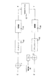
図1aおよび図1bは、本発明の原理の実施態様によるLDPC符号式ビット・インタリーバ変調システムのシステム・モデルを示すハイレベル・ブロック図である。図示のように、ビット・インタリーバ10は、入力LDPC符号(すなわちエンコーダ)12と変調器14の間に挿入される。この設計により、復号しきい値およびエラー・フロアは、より容易に識別され、判定される。図1bに示すように、ビット・インタリーバは、パリティ・ビットのブロック・インタリーブ16およびインタリーブされたビットの階層的割当て18を含むことができる。図1cは、パリティ・ビットのブロック・インタリーブ16の一例を示す図であり、図1dは、部分的にインタリーブされた符号化ビットの階層的割当ての一例を示す図である。
1a and 1b are high-level block diagrams illustrating a system model of an LDPC coded bit interleaver modulation system according to an embodiment of the principles of the present invention. As shown, the
図1eは、本発明の実施態様によるLDPC符号式ビット・インタリーバ変調システム20の通信システム・モデルを示す図である。送信機側は、BCHおよびLDPCエンコーダ12と、ビット・インタリーバ10と、変調器(コンステレーション・マッパ)14とで構成される。さらに、本明細書に開示のプロセスおよび方法を管理するためにプロセッサ8aおよびメモリ9aを使用することもできることは、当業者なら理解するであろう。受信機側は、復調器24と、ビット・デインタリーバ30と、LDPCおよびBCHデコーダ26と、プロセッサ8bおよびメモリ9bとを含む。この2値LDPC符号式システムでは、全ての符号化ビットが、集合{0、1}上で一様な分布を有する。Cはチャネル・エンコーダの出力を表し、YはAWGNチャネルの出力を表す。
FIG. 1e is a diagram illustrating a communication system model of an LDPC coded bit
図1fに示す実施例では、独立同分布(I.I.D.)ビット発生器32が、一般的なBICM(ビット・インタリーブ符号化変調)システム・モデルに組み付けられている。その結果として、入力C(符号化ビット)と出力Z(復調器出力のビット単位LLR)の間の増補チャネルは、以下の対称条件を満たす。
P(Z=z|C=0)=P(Z=−z|C=1) (2)
特定のラベリング手法によって生じる非一様ユークリッド距離スペクトルにより、ビット単位誤り保護は、ラベリング・ストリングのビット指標によって決まる。
In the embodiment shown in FIG. 1f, an independent isodistribution (ID) bit
P (Z = z | C = 0) = P (Z = -z | C = 1) (2)
Due to the non-uniform Euclidean distance spectrum produced by a particular labeling technique, bitwise error protection is determined by the bit index of the labeling string.
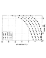
これに照らして、2QのQAMコンステレーション・マッパ(変調器)14、AWGNチャネル22および復調器24を含む合成チャネルは、Q個の2値入力AWGN(BIAWGN)サブチャネルに分解することができる。サブチャネルqの入力が離散集合{0、1}について一様な分布を有すると仮定すると、その容量は、復調器24の出力における入力Cl、qと対数尤度比(LLR)Zl、qの間の相互情報量に等しい。ここでは、例示のために、BRGCでラベリングした一様な1024QAMコンステレーションを考える。実際には、平均LLRの大きさの降順でIおよびVで示されるIブランチおよびQブランチのラベリング方式が同じであるとすると、ビット・レベルで(log21024)/2=5個の異なるサブチャネルが存在する。図2(a)は、ビット単位平均LLRをシンボルSNRの関数として表すグラフであり、図2(b)は、ビット単位容量をシンボルSNRの関数として表すグラフである。ここで、ビット単位チャネルは、対称BIAWGNのカテゴリに属し、条件付き確率P(Zl、q|Cl、q)(q=1、2、…、5)の関数である。これらのグラフから、特定のビット単位チャネルの信頼性は、そのビット単位平均LLRおよびビット単位容量に比例することが分かる。さらに、これら2つのメトリクスが反映する信頼性の順序は一致している。
In light of this, the combined channel including the 2 Q QAM constellation mapper (modulator) 14, the
図1gは、本発明のシミュレーションの各ステップを示すブロック流れ図である。34で入力と出力を比較し、ビット誤り率(BER)を計算する。 FIG. 1g is a block flow diagram illustrating the steps of the simulation of the present invention. At 34, the input and output are compared and a bit error rate (BER) is calculated.
サロゲート・チャネルを用いたビット・インタリーバの設計
サロゲートBECチャネル
上述のように、所与のLDPC符号アンサンブルの復号しきい値は、チャネルのタイプ自体によって決まるのではなく、主として有効チャネルの入力と出力の間の相互情報量によって決まることは、当業者なら分かるであろう。このことから、上記で定式化したQ個の非一様チャネルを、消失確率
Bit Interleaver Design with Surrogate Channel Surrogate BEC Channel As mentioned above, the decoding threshold for a given LDPC code ensemble is not determined by the channel type itself, but mainly by the input and output of the effective channel. Those skilled in the art will appreciate that this is determined by the amount of mutual information between them. From this, the Q non-uniform channels formulated above are
図3(a)は、2値入力Cおよび連続出力Zを有するAWGNチャネルを示す図である。図3(b)は、消失確率が1−I(Z;C)である図3(a)に示すAWGNチャネルのBECサロゲート・チャネルを示す図である。数式(3)から、2値AWGNチャネルおよび2値BECサロゲート・チャネルは、2つのチャネルの入力と出力の間の相互情報量が同じである。サロゲートBECを用いることにより、復号軌跡を追跡する作業は、各サブチャネルにおける消失確率の展開を観察する作業になるので、復号動作の調査は大幅に簡略化される。その結果、汎用密度発展アルゴリズムの「無限次元代数」によって生じる極めて高い複雑さが回避される。さらに、数式(3)におけるBEC置換により、真の復号軌跡からの逸脱の主原因の1つであるガウス近似を、後続の解析において呼び出す必要もなくなる。 FIG. 3A shows an AWGN channel having a binary input C and a continuous output Z. FIG. 3 (b) is a diagram showing the BEC surrogate channel of the AWGN channel shown in FIG. 3 (a) having an erasure probability of 1-I (Z; C). From equation (3), the binary AWGN channel and the binary BEC surrogate channel have the same mutual information between the input and output of the two channels. By using the surrogate BEC, the task of tracking the decoding trajectory becomes a task of observing the development of the erasure probability in each subchannel, so that the investigation of the decoding operation is greatly simplified. As a result, the extremely high complexity caused by the “infinite dimensional algebra” of the general density evolution algorithm is avoided. Furthermore, the BEC replacement in equation (3) eliminates the need to invoke the Gaussian approximation, which is one of the main causes of deviation from the true decoding trajectory, in subsequent analysis.
実際には、コンステレーション・マッパ(例えば変調器)、AWGNチャネルおよび復調器を含む合成チャネルは、誤り訂正能力が一様でない任意の組のメモリレス並列チャネルに一般化することができるので、数式(3)における置換がこの合成チャネルに限定されないことは、当業者なら分かるであろう。例としては、OFDMシステムの周波数選択サブチャネルや、誤り耐性の要件が一様でない体積ホログラム・メモリ(VHM)システムなどが挙げられる。 In practice, a composite channel including a constellation mapper (eg, modulator), AWGN channel, and demodulator can be generalized to any set of memoryless parallel channels with non-uniform error correction capabilities. One skilled in the art will appreciate that the substitution in (3) is not limited to this synthesis channel. Examples include frequency selective subchannels of OFDM systems and volume hologram memory (VHM) systems with non-uniform error resilience requirements.
LDPC符号化変調のビット・インタリーブ
表1は、符号化レートが1/4から9/10の範囲であるDVB−S2で標準化された11個のLDPC符号のVNDおよびCND次数分布の一例を示している。次数プロファイルの記述を簡略化するために、次数1のVNDが1つしかないことから、VNDの次数タイプを3つに減らす。さらに、その相手側と次数が異なるCNDは1つしかないので、CNDは一定と仮定することができる。このような小さな摂動は、対応する符号アンサンブルの性能に無視できるほどの影響しか及ぼさないことは既知である。しかし、この簡略化により、本発明のビット・インタリーバの設計の複雑さは大幅に低減される。
Bit Interleaving of LDPC Coded Modulation Table 1 shows an example of VND and CND degree distributions of 11 LDPC codes standardized by DVB-S2 whose coding rate ranges from 1/4 to 9/10. Yes. In order to simplify the description of the order profile, there is only one
本発明の原理の一実施態様では、発明者等は、2値LDPC符号のエッジ・パースペクティブ(edge−perspective)な変数ノード(VND)およびチェック・ノード(CND)の次数分布が、それぞれ In one implementation of the principles of the present invention, the inventors have determined that the degree distribution of edge-perspective variable nodes (VND) and check nodes (CND) of a binary LDPC code, respectively,
本発明のビット・インタリーバの基本関数は、L個の符号化ビットをサイズL/QのQ個のサブセットのみに分割し、次いでそれらをq番目(q=1、2、…、Q)のBECチャネルに割り当てるものである。便宜上、本明細書では、長さLの符号を「母符号」と呼び、そのQ個のサブセットのそれぞれを「サブコード」と呼ぶ。サブコードqの符号化ビットは全て、qで示されるサロゲートBECに割り当てられることになる。Q個のサブコードは、同じCNDパリティ制約を共有するので、ビット・インタリーバの結合により互いに相互作用することになる。従って、これらのサブコードは、非一様並列チャネル用に開発されたマルチレベル符号とは異なる。 The basic function of the bit interleaver of the present invention divides L coded bits into only Q subsets of size L / Q, and then divides them into q th (q = 1, 2,..., Q) BECs. Assign to a channel. For convenience, in this specification, a code having a length L is referred to as a “mother code”, and each of the Q subsets is referred to as a “subcode”. All the encoded bits of the subcode q are assigned to the surrogate BEC indicated by q. Since Q subcodes share the same CND parity constraint, they will interact with each other by combining bit interleavers. These subcodes are therefore different from multilevel codes developed for non-uniform parallel channels.
このLDPC符号のノード/エッジ・パースペクティブ次数分布から、平均消失確率は、各サブチャネルの消失確率の凸結合となり、重みはビット・インタリーバのプロファイルによって決定される。従って、ビット・インタリーバ設計の目標は、復号しきい値SNR(メッセージ・パッシング・アルゴリズムを使用するものと仮定する)が最小となるように、その次数プロファイルの制約付き最適化(母符号のVNDおよびCNDの次数分布に制約がある)となる。 From the node / edge perspective order distribution of the LDPC code, the average erasure probability is a convex combination of the erasure probabilities of the respective subchannels, and the weight is determined by the bit interleaver profile. Therefore, the goal of the bit interleaver design is to constrain the optimization of its order profile (the VND and the mother code) so that the decoding threshold SNR (assuming that the message passing algorithm is used) is minimized. CND order distribution is limited).
Q個のサブセットの基数は同じであるが、それらのVND次数分布は異なる形態をとることがある。q番目のBECサブチャネルに付帯するエッジの数がEqで与えられ、母符号のエッジの総数が最大でEになるものと仮定すると、q番目のサブコードに割り当てられるエッジの割合は、 Although the radix of the Q subsets is the same, their VND order distribution may take different forms. The number of edges attached to the q-th BEC subchannel is given by E q, the total number of edges of the mother code is assumed to be E at a maximum, the ratio of the edge assigned to the q-th sub-code,
![]()
![]()
LDPC符号アンサンブルの次数プロファイルの定義に従い、ビット・インタリーバ・アンサンブルの構成(Λ)は、Q個のエッジ・パースペクティブ次数シーケンスによって、 In accordance with the definition of the order profile of the LDPC code ensemble, the bit interleaver ensemble configuration (Λ) is defined by a sequence of Q edge perspective orders:
数式(9a)〜(9c)と数式(10)を組み合わせることにより、復号軌跡がビット・インタリーバ・アンサンブルの次数プロファイルΛによって決定されることが分かる。 By combining the equations (9a) to (9c) and the equation (10), it can be seen that the decoding trajectory is determined by the order profile Λ of the bit interleaver ensemble.
![]()
![]()
![]()
![]()
![]()
![]()
![]()
Θl=ΨΘl−1 (15)
ここでは、Ψは対角化することができ、その固有値の大きさは|τ1|≧|τ2|≧…≧|τQ|のように降順に配列されると仮定するが、これにより普遍性が失われることはない。その結果、反復復号が収束するための必要条件は、以下のようになる。
|τ1|<1 (16)
![]()
Θ l = ΨΘ l−1 (15)
Here, it is assumed that Ψ can be diagonalized and the magnitude of its eigenvalue is arranged in descending order as | τ 1 | ≧ | τ 2 | ≧… ≧ | τ Q | Universality will not be lost. As a result, the necessary conditions for iterative decoding to converge are as follows.
| Τ 1 | <1 (16)
要約すると、所与のLDPC符号がQ個の非一様チャネルを介して伝送され、メッセージ・パッシング・アルゴリズムで復号される場合、その性能は、エンコーダとチャネルの間に挿入されるビット・インタリーバの次数プロファイルΛによって決まることになる。特に、復号しきい値SNRγはΛの関数であり、この依存性は、γ(Λ)として明示的に表現することができる。数式(4)、(7)、(10)および(16)の制約を結合することにより、符号依存ビット・インタリーバの構成を、以下の制約付き(10)最適化問題の解として定式化することができる。
minΛ γ(Λ) (17a)
ただし|τ1|<1 (17b)
In summary, if a given LDPC code is transmitted over Q non-uniform channels and decoded with a message passing algorithm, the performance is that of the bit interleaver inserted between the encoder and the channel. It depends on the order profile Λ. In particular, the decoding threshold SNRγ is a function of Λ, and this dependency can be explicitly expressed as γ (Λ). Formulating the configuration of the sign-dependent bit interleaver as a solution to the following constrained (10) optimization problem by combining the constraints of equations (4), (7), (10) and (16) Can do.
min Λ γ (Λ) (17a )
However, | τ 1 | <1 (17b)
ここで、
here,
![]()
![]()
図4は、本発明の一実施態様による、AWGNチャネル条件下でビット・インタリーバをLDPC符号および変調に適合させる方法40を示すハイレベル流れ図である。上述のように、変調器、復調器および初期SNRを有するAWGNチャネルを含む合成チャネルについて、またΛで決定される所与のビット・インタリーバ構成について、最初に、等価なQ個の並列BIAWGNチャネルの容量を計算する(42)。この計算が終わったら、44で、計算した容量の同等性に基づいてQ個のサロゲート2元消失チャネル(BEC)によってQ個のBIAWGNチャネルをモデル化(近似)し、初期消失確率を得る(上記の数式3を参照)。次いで、消去確率がゼロ(0)に収束するかどうかについて、反復密度発展判定を行う(46a)(上記の数式9a〜9cを参照)。(I)収束すると判定された場合には、SNRを所与の刻み幅だけ低減する(47)。この所与の刻み幅は、例えば所望の解像度に基づいて決めることができ、例えば0.1dbとすることができることは、当業者なら分かるであろう。
FIG. 4 is a high-level flow diagram illustrating a
次いで、初期消失確率を決定し(48)、密度発展を使用して、消失確率がゼロに収束するかどうかを判定する(46b)。46bで収束すると判定された場合には、SNRを再度低減し(47)、このプロセスを繰り返す。46bで収束しないと判定された場合には、直前のSNRを、当該所与のビット・インタリーバ構成Λのしきい値SNRであるものとして特定し(50)、記憶する(58)。(II)ステップ46aで消失確率がゼロに収束しない場合には、SNRを所与の刻み幅だけ増加させ(52)、上記と同じプロセスを繰り返し、増加したSNRに対する消失確率を決定し(54)、密度発展を使用して、消失確率がゼロに収束するかどうかを判定する(46c)。46cで消失確率がゼロに収束する場合には、そのSNRを、当該所与のビット・インタリーバ構成Λの復号しきい値SNRであるものとして特定し(56)、次いでやはり記憶する(58)。ステップ46cで消失確率がゼロに収束しない場合には、SNRを再度増加させ(52)、このプロセスを上述のように引き続き行う。本発明の趣旨によって所与のビット・インタリーバ構成のしきい値SNRを決定する方法が複数存在することは、当業者なら分かるであろう。所与の、または最初のビット・インタリーバ構成Λについて内ループを実行したら、ビット・インタリーバ構成Λを変更し(60)、このプロセスを再び実行する。このプロセス中のある時点で、例えば時間制約および/または確度要件に応じて、ビット・インタリーバ構成を選択し、この選択に従ってビット・インタリーバを構成する(62)。 The initial erasure probability is then determined (48) and density evolution is used to determine if the erasure probability converges to zero (46b). If it is determined to converge at 46b, the SNR is reduced again (47) and the process is repeated. If it is determined in 46b that the convergence does not occur, the immediately preceding SNR is specified as being the threshold SNR of the given bit interleaver configuration Λ (50) and stored (58). (II) If the erasure probability does not converge to zero in step 46a, increase the SNR by a given step size (52) and repeat the same process as above to determine the erasure probability for the increased SNR (54) , Determine if the probability of disappearance converges to zero using density evolution (46c). If the erasure probability converges to zero at 46c, the SNR is identified as being the decoding threshold SNR for the given bit interleaver configuration Λ (56) and then also stored (58). If the disappearance probability does not converge to zero in step 46c, the SNR is increased again (52) and the process continues as described above. Those skilled in the art will appreciate that there are multiple ways to determine the threshold SNR for a given bit interleaver configuration in accordance with the spirit of the invention. Once the inner loop is performed for a given or initial bit interleaver configuration Λ, the bit interleaver configuration Λ is changed (60) and the process is performed again. At some point in the process, a bit interleaver configuration is selected, for example according to time constraints and / or accuracy requirements, and a bit interleaver is configured according to the selection (62).
また、最小のしきい値SNRを得るためには、ビット・インタリーバ構成Λを変更しなければならないことは、当業者なら分かるであろう。これを行う際には、最低の復号しきい値SNRをもたらす正しいΛを見つけることは困難である場合もあり、多くのサンプルをテストすることになることもあることが分かる。従って、停止点(62)を主観的なものにしてユーザ/設計者が設定するという、代替の実施態様も考えられる。これは、テストを停止し、その時点で得られている最良の、すなわち最低の復号しきい値SNRをとるブルート・フォース手法と呼ばれることがある。例えば、1つのブルート・フォース手法は、単に復号しきい値SNRのテストに関するタイミング制約である場合もある。 Also, those skilled in the art will appreciate that the bit interleaver configuration Λ must be changed to obtain the minimum threshold SNR. It will be appreciated that in doing this it may be difficult to find the correct Λ that results in the lowest decoding threshold SNR, and many samples may be tested. Thus, alternative embodiments are conceivable where the user / designer sets the stop point (62) to be subjective. This is sometimes referred to as a brute force approach that stops the test and takes the best or lowest decoding threshold SNR obtained at that time. For example, one brute force approach may simply be a timing constraint for the decoding threshold SNR test.
最小または最低のしきい値SNRが決定または選択されたら(62)、対応するビット・インタリーバ構成Λに従ってビット・インタリーバを構成する。そのように構成したら、符号をビット・インタリーブすることができる。 Once the minimum or minimum threshold SNR is determined or selected (62), the bit interleaver is configured according to the corresponding bit interleaver configuration Λ. If so configured, the codes can be bit interleaved.
提案するビット・インタリーバの設計方法の有効性を検証するために、発明者等は、DVB−S2/T2標準に指定される短いブロック長(L=16200)のLDPC符号をビット・インタリーバの母符号として使用して、次世代のケーブル・チャネルでの採用が提案されている、BRGCでラベリングした2乗1024QAMおよび4096QAMコンステレーションを考える。 In order to verify the effectiveness of the proposed bit interleaver design method, the inventors changed the short block length (L = 16200) LDPC code specified in the DVB-S2 / T2 standard to the bit interleaver mother code. Let us consider BRGC-labeled square 1024QAM and 4096QAM constellations that have been proposed for use in next generation cable channels.
本発明が提供する解析的研究とは対称的に、「CND衝突」を回避することを基本とするアドホックなビット・インタリーブ方法がDVB−T2では使用されており、これはDVB−C2に対しても提案されている。ここで、「CND衝突」という用語は、3つ以上のビットが同じシンボルにマッピングされ、同じパリティ方程式でチェックされる現象を指すものである。一般に、CND衝突を完全に回避することは困難であり、実現可能性をブルート・フォースに探索すれば、計算負荷の高い組合せプログラミング問題を必然的に伴う。それでも、DVBS2符号の疑似周期的構造の規則性を利用することにより、研究者は、一部の符号レートについてはCND衝突の発生を回避することができるビット・インタリーブ手法を考案している。 In contrast to the analytical work provided by the present invention, an ad hoc bit interleaving method based on avoiding “CND collision” is used in DVB-T2, which is different from DVB-C2. Has also been proposed. Here, the term “CND collision” refers to a phenomenon in which three or more bits are mapped to the same symbol and checked with the same parity equation. In general, it is difficult to completely avoid CND collision, and searching for feasibility in a brute force necessarily involves a computationally expensive combinatorial programming problem. Nevertheless, by utilizing the regularity of the quasi-periodic structure of the DVBS2 code, researchers have devised a bit interleaving technique that can avoid the occurrence of CND collisions for some code rates.
しかし、発明者等は、特に高次数のVNDを共通のCNDを介して低次数のVNDに接続する場合には、CND衝突の発生は必ずしも悪いとは言えないと考えている。それは、高次数のVNDが、通常はより信頼性の高いLLRメッセージを担持しており、このことが、低次数のVNDが速い復号収束を達成する助けになる可能性があるからである。従って、発明者等の設計およびシミュレーションでは、CND衝突の発生を無視し、符号化ビットを、それらの自然な順序で、Λによって指定される最適な次数プロファイルに従って、単純にコンステレーション・マッパに割り当てる。 However, the inventors believe that the occurrence of a CND collision is not necessarily bad particularly when a high-order VND is connected to a low-order VND via a common CND. This is because higher order VNDs usually carry more reliable LLR messages, which may help lower order VNDs achieve fast decoding convergence. Thus, in our design and simulation, we ignore the occurrence of CND collisions and simply assign the coded bits to their constellation mapper in their natural order according to the optimal order profile specified by Λ. .
本項を通じて、発明者等は、モンテカルロ・シミュレーションの結果を考慮し、共通の基準として「非インタリーブ」(連続的なビットのグループ化およびコンステレーション・マッパへのマッピング)を使用している。インタリーブ・タイプ/非インタリーブ・タイプのそれぞれで、フレーム誤りが50検出された時点で、シミュレーションの試行を終了している。2種類の符号レート(11/15および7/9)および2種類の変調形式(4096QAMおよび1024QAM)について、情報ビットの復号BERの比較を、図5から図8に与える。これらの曲線から、サロゲートBECチャネルを用いて設計されたビット・インタリーバは、CND衝突を回避しようとするインタリーバに優る、有意なパワーの節約(0.4〜0.7dBの利得)を達成することができることが分かる。これに加えて、どちらの場合でも、ビット・インタリーブを行わない場合よりも性能が優れており、このことは、不規則なLDPC符号を非一様なチャネルを介して伝送するときには、スペクトル効率とパワー効率の兼ね合いを図るために、専用ビット・インタリーバが必要であることを実証している。 Throughout this section, the inventors have used “non-interleaved” (continuous bit grouping and mapping to constellation mapper) as a common criterion, taking into account the results of Monte Carlo simulations. In each of the interleave type and non-interleave type, the simulation trial is completed when 50 frame errors are detected. A comparison of the decoded BER of the information bits for the two code rates (11/15 and 7/9) and the two modulation formats (4096 QAM and 1024 QAM) is given in FIGS. From these curves, a bit interleaver designed with a surrogate BEC channel achieves significant power savings (0.4-0.7 dB gain) over an interleaver trying to avoid CND collisions. You can see that In addition, in both cases, the performance is better than without bit interleaving, which means that when transmitting irregular LDPC codes over a non-uniform channel, spectral efficiency and It has been demonstrated that a dedicated bit interleaver is necessary to balance power efficiency.
当業者なら、本明細書の教示に基づき、本発明の原理の上記その他の特性および利点を容易に理解することができる。本発明の原理の教示は、様々な形態のハードウェア、ソフトウェア、ファームウェア、特殊目的プロセッサ、またはそれらの組合せによって実施することができることを理解されたい。 Those skilled in the art can readily appreciate these and other features and advantages of the principles of the present invention based on the teachings herein. It should be understood that the teachings of the present principles may be implemented by various forms of hardware, software, firmware, special purpose processors, or combinations thereof.
本発明の原理の教示は、ハードウェアとソフトウェアの組合せとして実施されることが最も好ましい。さらに、ソフトウェアは、プログラム記憶装置に実装されたアプリケーション・プログラムとして実施することができる。アプリケーション・プログラムは、任意の適当なアーキテクチャを備える機械にアップロードして実行することができる。この機械は、1つまたは複数の中央処理装置(CPU)などのハードウェア、ランダム・アクセス・メモリ(RAM)、および入出力(I/O)インタフェースを有するコンピュータ・プラットフォームで実施されることが好ましい。コンピュータ・プラットフォームは、オペレーティング・システムおよびマイクロ命令コードも備えることができる。本明細書に記載する様々なプロセスおよび機能は、CPUによって実行することができる、マイクロ命令コードの一部またはアプリケーション・プログラムの一部あるいはそれらの組合せの何れかにすることができる。さらに、追加のデータ記憶装置や印刷装置など、その他の様々な周辺装置をコンピュータ・プラットフォームに接続することもできる。 Most preferably, the teachings of the principles of the present invention are implemented as a combination of hardware and software. Further, the software can be implemented as an application program implemented in a program storage device. Application programs can be uploaded and executed on machines with any suitable architecture. The machine is preferably implemented on a computer platform having hardware such as one or more central processing units (CPUs), a random access memory (RAM), and input / output (I / O) interfaces. . The computer platform can also include an operating system and microinstruction code. The various processes and functions described herein can be either part of the microinstruction code or part of the application program or combinations thereof that can be executed by the CPU. In addition, various other peripheral devices may be connected to the computer platform such as an additional data storage device and a printing device.
さらに、添付の図面に示すシステム構成要素および方法の一部はソフトウェアで実施することが好ましいので、システム構成要素間またはプロセス機能ブロック間の実際の接続は、本発明の原理をプログラミングする方法によって異なっていてもよいことも理解されたい。本明細書の教示があれば、当業者なら、本発明の原理の上記の実施態様または構成およびそれと同様の実施態様または構成を思いつくことができるであろう。 Further, since some of the system components and methods shown in the accompanying drawings are preferably implemented in software, the actual connections between system components or between process functional blocks will vary depending on the method of programming the principles of the present invention. It should also be understood that it may be. Given the teachings herein, one of ordinary skill in the related art will be able to contemplate these and similar embodiments or configurations of the principles of the invention.
本明細書では、添付の図面を参照して例示的な実施例について述べたが、本発明の原理は、これらの具体的な実施例に限定されるわけではなく、当業者なら、本発明の原理の範囲または趣旨を逸脱することなく様々な変更および修正をそれらの実施例に加えることができることを理解されたい。そうした変更および修正は全て、添付の特許請求の範囲に記載する本発明の原理の範囲に含まれるものとする。
[付記1]
ビット・インタリーバをLDPC符号および変調に適合させる方法であって、
非一様並列AWGNチャネルのビット単位容量を計算するステップ(42)と、
前記AWGNチャネルを、消失確率を有する1組のQ個のサロゲート2元消失チャネル(BEC)で近似するステップ(44)と、
消失確率密度分布を用いて、復号しきい値信号対雑音比(SNR)が、ビット・インタリーバ構成に対して最低の復号しきい値信号対雑音比をもたらすかどうかを判定するステップ(46、58、60)と、
判定した最低の復号しきい値信号対雑音比に対応するビット・インタリーバ構成に基づいて、前記ビット・インタリーバを構成するステップ(58)と、
を含む、前記方法。
[付記2]
前記判定するステップ(46)が、
前記消失確率がゼロに収束する場合に、前記SNRを所定の刻み幅だけ低減するステップ(47)と、
前記低減したSNRに対する消失確率を決定するステップ(48)と、
前記低減したSNRの消失確率がゼロに収束するかどうかを判定するステップ(46b)と、
前記消失確率がゼロに収束しない場合に、前記低減前のSNRをビット・インタリーバ構成の復号しきい値SNRとして特定するステップ(50)と、
をさらに含む、付記1に記載の方法。
[付記3]
前記判定するステップ(46)が、
前記消失確率がゼロに収束しない場合に、前記SNRを所定の刻み幅だけ増加するステップ(52)と、
前記増加したSNRに対する消失確率を決定するステップ(54)と、
前記増加したSNRの消失確率がゼロに収束するかどうかを判定するステップ(46c)と、
前記消失確率がゼロに収束する場合に、前記増加したSNRをビット・インタリーバ構成の復号しきい値SNRとして特定するステップ(56)と、
をさらに含む、付記2に記載の方法。
[付記4]
各ビット・インタリーバ構成および対応する決定した最低の復号しきい値SNRを記憶するステップ(58)と、
ビット・インタリーバ構成(Λ)を変更するステップ(60)と、
前記判定するステップを実行して、前記変更したビット・インタリーバ構成の復号しきい値SNRを決定するステップと、
前記最低の復号しきい値SNRを有するビット・インタリーバ構成を選択するステップ(62)と、
前記選択した構成を有するビット・インタリーバを構成するステップ(62)と、
をさらに含む、付記3に記載の方法。
[付記5]
前記計算したビット単位容量が、前記並列AWGNチャネルの2値入力と有効出力の間の相互情報量に基づいてビット単位容量を計算するステップを含み、前記近似が、前記計算したビット単位容量の同等性に基づいて行われる、付記1に記載の方法。
[付記6]
前記構成したビット・インタリーバを用いて前記符号をビット・インタリーブするステップ(58)をさらに含む、付記1に記載の方法。
[付記7]
前記判定するステップ(46)が、前記復号しきい値SNRから、所定の線形差分方程式からモデル化された平均消失確率密度分布を決定するステップをさらに含む、付記2に記載の方法。
[付記8]
前記平均消失確率を決定する前記ステップが、
前記LDPC符号のノード/エッジ・パースペクティブ次数分布を識別するステップと、
各サブチャネルの消失確率の凸結合を行うステップと、
をさらに含む、付記7に記載の方法。
[付記9]
前記密度分布のモデル化が、
![]()
[付記10]
ビット・インタリーバの次数プロファイルの最適化を制約することにより、前記復号しきい値SNRを最小にするステップをさらに含む、付記3に記載の方法。
[付記11]
ビット・インタリーバをLDPC符号および変調に適合させる装置であって、
非一様並列AWGNチャネルのビット単位容量を計算し、前記AWGNチャネルを1組のサロゲート2元消失チャネルで近似し、消失確率密度分布を用いて1つまたは複数のビット・インタリーバ構成のそれぞれに対して復号しきい値SNRを決定するように構成されたプロセッサ(8)であり、決定した各SNRに対して消失確率を決定するプロセッサ(8)と、
前記1つまたは複数の決定した復号しきい値SNRおよび対応するビット・インタリーバ構成を記憶するメモリ(9)と、
記憶された1つまたは複数の決定された復号しきい値SNRから選択された最低の復号しきい値SNRに対応するビット・インタリーバ構成に基づいて前記プロセッサによって構成されたビット・インタリーバ(10)と、
を備える、前記装置。
[付記12]
前記プロセッサが、前記決定された1つまたは複数の復号しきい値SNRから、所定の線形差分方程式からモデル化された平均消失確率密度分布をさらに決定する、付記11に記載の装置。
[付記13]
前記並列AWGNチャネルの2値入力と有効出力の間の相互情報量に基づいて前記ビット単位容量を計算する、付記11に記載の装置。
[付記14]
前記ビット・インタリーバが、各しきい値SNRに対応する決定された消失確率のそれぞれから導出された復号反復の復号収束条件に基づいて前記符号のビット・インタリーブを行うように構成される、付記11に記載の装置。
[付記15]
前記プロセッサが、前記LDPC符号のノード/エッジ・パースペクティブ次数分布を識別し、各サブチャネルの消失確率の凸結合を行うことによって、前記平均消失確率を決定する、付記12に記載の装置。
[付記16]
前記密度分布のモデル化が、
[付記17]
受信側ビット・インタリーバをLDPC符号および変調に適合させる方法であって、
非一様並列AWGNチャネルのビット単位容量を計算するステップ(42)と、
前記AWGNチャネルを、消失確率を有する1組のQ個のサロゲート2元消失チャネル(BEC)で近似するステップ(44)と、
消失確率密度分布を用いて、復号しきい値信号対雑音比(SNR)が、ビット・インタリーバ構成に対して最低の復号しきい値信号対雑音比をもたらすかどうかを判定するステップ(46、58、60)と、
判定した最低の復号しきい値信号対雑音比に対応するビット・インタリーバ構成に基づいて、前記受信側ビット・インタリーバを構成するステップ(58)と、
を含む、前記方法。
[付記18]
前記判定するステップ(46)が、
前記消失確率がゼロに収束する場合に、前記SNRを所定の刻み幅だけ低減するステップ(47)と、
前記低減したSNRに対する消失確率を決定するステップ(48)と、
前記低減したSNRの消失確率がゼロに収束するかどうかを判定するステップ(46b)と、
前記消失確率がゼロに収束しない場合に、前記低減前のSNRをビット・インタリーバ構成の復号しきい値SNRとして特定するステップ(50)と、
をさらに含む、付記17に記載の方法。
[付記19]
前記判定するステップ(46)が、
前記消失確率がゼロに収束しない場合に、前記SNRを所定の刻み幅だけ増加するステップ(52)と、
前記増加したSNRに対する消失確率を決定するステップ(54)と、
前記増加したSNRの消失確率がゼロに収束するかどうかを判定するステップ(46c)と、
前記消失確率がゼロに収束する場合に、前記増加したSNRをビット・インタリーバ構成の復号しきい値SNRとして特定するステップ(56)と、
をさらに含む、付記18に記載の方法。
[付記20]
各ビット・インタリーバ構成および対応する決定した最低の復号しきい値SNRを記憶するステップ(58)と、
ビット・インタリーバ構成(Λ)を変更するステップ(60)と、
前記判定ステップを実行して、前記変更したビット・インタリーバ構成の復号しきい値SNRを決定するステップと、
前記最低の復号しきい値SNRを有するビット・インタリーバ構成を選択するステップ(62)と、
前記選択した構成を有するビット・インタリーバを構成するステップ(62)と、
をさらに含む、付記19に記載の方法。
[付記21]
前記計算したビット単位容量が、前記並列AWGNチャネルの2値入力と有効出力の間の相互情報量に基づいてビット単位容量を計算するステップを含み、前記近似が、前記計算したビット単位容量の同等性に基づいて行われる、付記17に記載の方法。
[付記22]
前記構成したビット・インタリーバを用いて前記符号をビット・インタリーブするステップ(58)をさらに含む、付記17に記載の方法。
[付記23]
前記判定するステップ(46)が、前記復号しきい値SNRから、所定の線形差分方程式からモデル化された平均消失確率密度分布を決定するステップをさらに含む、付記18に記載の方法。
[付記24]
前記平均消失確率を決定する前記ステップが、
前記LDPC符号のノード/エッジ・パースペクティブ次数分布を識別するステップと、
各サブチャネルの消失確率の凸結合を行うステップと、
をさらに含む、付記23に記載の方法。
[付記25]
前記密度分布のモデル化が、
[付記26]
ビット・インタリーバの次数プロファイルの最適化を制約することにより、前記復号しきい値SNRを最小にするステップをさらに含む、付記19に記載の方法。
[付記27]
受信側ビット・インタリーバをLDPC符号および変調に適合させる装置であって、
非一様並列AWGNチャネルのビット単位容量を計算し、前記AWGNチャネルを1組のサロゲート2元消失チャネルで近似し、消失確率密度分布を用いて1つまたは複数のビット・インタリーバ構成のそれぞれに対して復号しきい値SNRを決定するように構成されたプロセッサ(8)であり、決定した各SNRに対して消失確率を決定するプロセッサ(8)と、
前記1つまたは複数の決定した復号しきい値SNRおよび対応するビット・インタリーバ構成を記憶するメモリ(9)と、
記憶された1つまたは複数の決定された復号しきい値SNRから選択された最低の復号しきい値SNRに対応するビット・インタリーバ構成に基づいて前記プロセッサによって構成された受信側ビット・インタリーバ(10)と、
を備える、前記装置。
[付記28]
前記プロセッサが、前記決定された1つまたは複数の復号しきい値SNRから、所定の線形差分方程式からモデル化された平均消失確率密度分布をさらに決定する、付記27に記載の装置。
[付記29]
前記並列AWGNチャネルの2値入力と有効出力の間の相互情報量に基づいて前記ビット単位容量を計算する、付記27に記載の装置。
[付記30]
前記ビット・インタリーバが、各しきい値SNRに対応する決定された消失確率のそれぞれから導出された復号反復の復号収束条件に基づいて前記符号のビット・インタリーブを行うように構成される、付記27に記載の装置。
[付記31]
前記プロセッサが、前記LDPC符号のノード/エッジ・パースペクティブ次数分布を識別し、各サブチャネルの消失確率の凸結合を行うことによって、前記平均消失確率を決定する、付記28に記載の装置。
[付記32]
前記密度分布のモデル化が、
[Appendix 1]
A method for adapting a bit interleaver to LDPC codes and modulations, comprising:
Calculating the bit unit capacity of the non-uniform parallel AWGN channel (42);
Approximating the AWGN channel with a set of Q surrogate binary erasure channels (BECs) with erasure probabilities (44);
Using the erasure probability density distribution, determining whether the decoding threshold signal-to-noise ratio (SNR) results in the lowest decoding threshold signal-to-noise ratio for the bit interleaver configuration (46, 58). 60)
Configuring the bit interleaver based on the bit interleaver configuration corresponding to the determined lowest decoding threshold signal-to-noise ratio;
Said method.
[Appendix 2]
The step of determining (46)
Reducing the SNR by a predetermined step size when the probability of erasure converges to zero (47);
Determining an erasure probability for the reduced SNR (48);
Determining whether the reduced SNR disappearance probability converges to zero (46b);
Identifying the SNR before reduction as a decoding threshold SNR of a bit interleaver configuration when the erasure probability does not converge to zero;
The method according to
[Appendix 3]
The step of determining (46)
Increasing the SNR by a predetermined step size when the erasure probability does not converge to zero (52);
Determining an erasure probability for the increased SNR (54);
Determining (46c) whether the increased SNR disappearance probability converges to zero;
Identifying the increased SNR as a decoding threshold SNR of a bit interleaver configuration when the erasure probability converges to zero;
The method according to
[Appendix 4]
Storing (58) each bit interleaver configuration and corresponding determined minimum decoding threshold SNR;
Changing the bit interleaver configuration (Λ) (60);
Performing the determining step to determine a decoding threshold SNR for the modified bit interleaver configuration;
Selecting a bit interleaver configuration having the lowest decoding threshold SNR;
Configuring a bit interleaver having the selected configuration (62);
The method according to appendix 3, further comprising:
[Appendix 5]
The calculated bit unit capacity includes calculating a bit unit capacity based on a mutual information amount between a binary input and an effective output of the parallel AWGN channel, and the approximation is equivalent to the calculated bit unit capacity. The method according to
[Appendix 6]
The method of
[Appendix 7]
The method of
[Appendix 8]
Said step of determining said mean erasure probability comprises:
Identifying a node / edge perspective order distribution of the LDPC code;
Performing a convex combination of the erasure probabilities of each subchannel;
The method according to appendix 7, further comprising:
[Appendix 9]
The modeling of the density distribution is
![]()
[Appendix 10]
The method of claim 3, further comprising minimizing the decoding threshold SNR by constraining optimization of a bit interleaver order profile.
[Appendix 11]
An apparatus for adapting a bit interleaver to LDPC codes and modulations,
Calculate the bit-wise capacity of a non-uniform parallel AWGN channel, approximate the AWGN channel with a set of surrogate binary erasure channels, and use erasure probability density distribution for each of one or more bit interleaver configurations A processor (8) configured to determine a decoding threshold SNR, wherein the processor (8) determines an erasure probability for each determined SNR;
A memory (9) for storing the one or more determined decoding threshold SNRs and corresponding bit interleaver configurations;
A bit interleaver (10) configured by the processor based on a bit interleaver configuration corresponding to a lowest decoding threshold SNR selected from one or more determined decoding thresholds SNR stored; ,
Comprising the apparatus.
[Appendix 12]
The apparatus of claim 11, wherein the processor further determines an average erasure probability density modeled from a predetermined linear difference equation from the determined one or more decoding threshold SNRs.
[Appendix 13]
The apparatus according to claim 11, wherein the bit unit capacity is calculated based on a mutual information amount between a binary input and an effective output of the parallel AWGN channel.
[Appendix 14]
Appendix 11 wherein the bit interleaver is configured to perform bit interleaving of the code based on a decoding convergence condition of a decoding iteration derived from each of the determined erasure probabilities corresponding to each threshold SNR. The device described in 1.
[Appendix 15]
The apparatus of
[Appendix 16]
The modeling of the density distribution is
[Appendix 17]
A method for adapting a receiving bit interleaver to LDPC code and modulation comprising:
Calculating the bit unit capacity of the non-uniform parallel AWGN channel (42);
Approximating the AWGN channel with a set of Q surrogate binary erasure channels (BECs) with erasure probabilities (44);
Using the erasure probability density distribution, determining whether the decoding threshold signal-to-noise ratio (SNR) results in the lowest decoding threshold signal-to-noise ratio for the bit interleaver configuration (46, 58). 60)
Configuring the receiving bit interleaver based on a bit interleaver configuration corresponding to the determined lowest decoding threshold signal-to-noise ratio;
Said method.
[Appendix 18]
The step of determining (46)
Reducing the SNR by a predetermined step size when the probability of erasure converges to zero (47);
Determining an erasure probability for the reduced SNR (48);
Determining whether the reduced SNR disappearance probability converges to zero (46b);
Identifying the SNR before reduction as a decoding threshold SNR of a bit interleaver configuration when the erasure probability does not converge to zero;
The method according to appendix 17, further comprising:
[Appendix 19]
The step of determining (46)
Increasing the SNR by a predetermined step size when the erasure probability does not converge to zero (52);
Determining an erasure probability for the increased SNR (54);
Determining (46c) whether the increased SNR disappearance probability converges to zero;
Identifying the increased SNR as a decoding threshold SNR of a bit interleaver configuration when the erasure probability converges to zero;
The method according to
[Appendix 20]
Storing (58) each bit interleaver configuration and corresponding determined minimum decoding threshold SNR;
Changing the bit interleaver configuration (Λ) (60);
Performing the determining step to determine a decoding threshold SNR for the modified bit interleaver configuration;
Selecting a bit interleaver configuration having the lowest decoding threshold SNR;
Configuring a bit interleaver having the selected configuration (62);
The method according to appendix 19, further comprising:
[Appendix 21]
The calculated bit unit capacity includes calculating a bit unit capacity based on a mutual information amount between a binary input and an effective output of the parallel AWGN channel, and the approximation is equivalent to the calculated bit unit capacity. The method according to appendix 17, which is performed based on sex.
[Appendix 22]
The method of claim 17, further comprising the step of bit interleaving the code using the configured bit interleaver (58).
[Appendix 23]
The method of
[Appendix 24]
Said step of determining said mean erasure probability comprises:
Identifying a node / edge perspective order distribution of the LDPC code;
Performing a convex combination of the erasure probabilities of each subchannel;
The method according to appendix 23, further comprising:
[Appendix 25]
The modeling of the density distribution is
[Appendix 26]
The method of claim 19, further comprising minimizing the decoding threshold SNR by constraining optimization of a bit interleaver order profile.
[Appendix 27]
An apparatus for adapting a receiving bit interleaver to LDPC code and modulation comprising:
Calculate the bit-wise capacity of a non-uniform parallel AWGN channel, approximate the AWGN channel with a set of surrogate binary erasure channels, and use erasure probability density distribution for each of one or more bit interleaver configurations A processor (8) configured to determine a decoding threshold SNR, wherein the processor (8) determines an erasure probability for each determined SNR;
A memory (9) for storing the one or more determined decoding threshold SNRs and corresponding bit interleaver configurations;
A receiver bit interleaver (10) configured by the processor based on a bit interleaver configuration corresponding to a lowest decoding threshold SNR selected from one or more determined decoding threshold SNRs stored. )When,
Comprising the apparatus.
[Appendix 28]
28. The apparatus of clause 27, wherein the processor further determines an average erasure probability density distribution modeled from a predetermined linear difference equation from the determined one or more decoding threshold SNRs.
[Appendix 29]
28. The apparatus according to appendix 27, wherein the bit unit capacity is calculated based on a mutual information amount between a binary input and an effective output of the parallel AWGN channel.
[Appendix 30]
Item 27. The bit interleaver is configured to perform bit interleaving of the code based on a decoding convergence condition of a decoding iteration derived from each of the determined erasure probabilities corresponding to each threshold SNR. The device described in 1.
[Appendix 31]
29. The apparatus of clause 28, wherein the processor determines the average erasure probability by identifying a node / edge perspective order distribution of the LDPC code and performing a convex combination of erasure probabilities for each subchannel.
[Appendix 32]
The modeling of the density distribution is
Claims (32)
非一様並列AWGNチャネルのビット単位容量を計算するステップと、
前記AWGNチャネルを、消失確率を有する1組のQ個のサロゲート2元消失チャネル(BEC)で近似するステップと、
消失確率密度分布を用いて、復号しきい値信号対雑音比(SNR)が、ビット・インタリーバ構成に対して最低の復号しきい値信号対雑音比をもたらすかどうかを判定するステップと、
判定した最低の復号しきい値信号対雑音比に対応するビット・インタリーバ構成に基づいて、前記ビット・インタリーバを構成するステップと、
を含む、前記方法。 A method for adapting a bit interleaver to LDPC codes and modulations, comprising:
Calculating the bit unit capacity of the non-uniform parallel AWGN channel;
Approximating the AWGN channel with a set of Q surrogate binary erasure channels (BEC) with erasure probability;
Determining whether a decoding threshold signal-to-noise ratio (SNR) results in the lowest decoding threshold signal-to-noise ratio for a bit interleaver configuration using an erasure probability density distribution;
Configuring the bit interleaver based on a bit interleaver configuration corresponding to the determined lowest decoding threshold signal-to-noise ratio;
Said method.
前記消失確率がゼロに収束する場合に、前記SNRを所定の刻み幅だけ低減するステップと、
前記低減したSNRに対する消失確率を決定するステップと、
前記低減したSNRの消失確率がゼロに収束するかどうかを判定するステップと、
前記消失確率がゼロに収束しない場合に、前記低減前のSNRをビット・インタリーバ構成の復号しきい値SNRとして特定するステップと、
をさらに含む、請求項1に記載の方法。 The step of determining comprises
Reducing the SNR by a predetermined step size when the erasure probability converges to zero;
Determining an erasure probability for the reduced SNR;
Determining if the reduced SNR disappearance probability converges to zero;
Identifying the SNR before reduction as a decoding threshold SNR of a bit interleaver configuration when the erasure probability does not converge to zero;
The method of claim 1, further comprising:
前記消失確率がゼロに収束しない場合に、前記SNRを所定の刻み幅だけ増加するステップと、
前記増加したSNRに対する消失確率を決定するステップと、
前記増加したSNRの消失確率がゼロに収束するかどうかを判定するステップと、
前記消失確率がゼロに収束する場合に、前記増加したSNRをビット・インタリーバ構成の復号しきい値SNRとして特定するステップと、
をさらに含む、請求項2に記載の方法。 The step of determining comprises
Increasing the SNR by a predetermined step size when the erasure probability does not converge to zero;
Determining a probability of disappearance for the increased SNR;
Determining whether the increased SNR disappearance probability converges to zero;
Identifying the increased SNR as a decoding threshold SNR of a bit interleaver configuration when the erasure probability converges to zero;
The method of claim 2 further comprising:
ビット・インタリーバ構成を変更するステップと、
前記判定するステップを実行して、前記変更したビット・インタリーバ構成の復号しきい値SNRを決定するステップと、
前記最低の復号しきい値SNRを有するビット・インタリーバ構成を選択するステップと、
前記選択した構成を有するビット・インタリーバを構成するステップと、
をさらに含む、請求項3に記載の方法。 Storing each bit interleaver configuration and corresponding determined minimum decoding threshold SNR;
Changing the bit interleaver configuration;
Performing the determining step to determine a decoding threshold SNR for the modified bit interleaver configuration;
Selecting a bit interleaver configuration having the lowest decoding threshold SNR;
Configuring a bit interleaver having the selected configuration;
The method of claim 3, further comprising:
前記LDPC符号のノード/エッジ・パースペクティブ次数分布を識別するステップと、
各サブチャネルの消失確率の凸結合を行うステップと、
をさらに含む、請求項7に記載の方法。 Said step of determining said mean erasure probability comprises:
Identifying a node / edge perspective order distribution of the LDPC code;
Performing a convex combination of the erasure probabilities of each subchannel;
The method of claim 7, further comprising:
非一様並列AWGNチャネルのビット単位容量を計算し、前記AWGNチャネルを1組のサロゲート2元消失チャネルで近似し、消失確率密度分布を用いて1つまたは複数のビット・インタリーバ構成のそれぞれに対して復号しきい値SNRを決定するように構成されたプロセッサであり、決定した各SNRに対して消失確率を決定するプロセッサと、
前記1つまたは複数の決定した復号しきい値SNRおよび対応するビット・インタリーバ構成を記憶するメモリと、
記憶された1つまたは複数の決定された復号しきい値SNRから選択された最低の復号しきい値SNRに対応するビット・インタリーバ構成に基づいて前記プロセッサによって構成されたビット・インタリーバと、
を備える、前記装置。 An apparatus for adapting a bit interleaver to LDPC codes and modulations,
Calculate the bit-wise capacity of a non-uniform parallel AWGN channel, approximate the AWGN channel with a set of surrogate binary erasure channels, and use erasure probability density distribution for each of one or more bit interleaver configurations A processor configured to determine a decoding threshold SNR, wherein the processor determines an erasure probability for each determined SNR;
A memory storing the one or more determined decoding threshold SNRs and corresponding bit interleaver configurations;
A bit interleaver configured by the processor based on a bit interleaver configuration corresponding to the lowest decoding threshold SNR selected from the stored one or more determined decoding threshold SNRs;
Comprising the apparatus.
非一様並列AWGNチャネルのビット単位容量を計算するステップと、
前記AWGNチャネルを、消失確率を有する1組のQ個のサロゲート2元消失チャネル(BEC)で近似するステップと、
消失確率密度分布を用いて、復号しきい値信号対雑音比(SNR)が、ビット・インタリーバ構成に対して最低の復号しきい値信号対雑音比をもたらすかどうかを判定するステップと、
判定した最低の復号しきい値信号対雑音比に対応するビット・インタリーバ構成に基づいて、前記受信側ビット・インタリーバを構成するステップと、
を含む、前記方法。 A method for adapting a receiving bit interleaver to LDPC code and modulation comprising:
Calculating the bit unit capacity of the non-uniform parallel AWGN channel;
Approximating the AWGN channel with a set of Q surrogate binary erasure channels (BEC) with erasure probability;
Determining whether a decoding threshold signal-to-noise ratio (SNR) results in the lowest decoding threshold signal-to-noise ratio for a bit interleaver configuration using an erasure probability density distribution;
Configuring the receiving bit interleaver based on a bit interleaver configuration corresponding to the determined lowest decoding threshold signal-to-noise ratio;
Said method.
前記消失確率がゼロに収束する場合に、前記SNRを所定の刻み幅だけ低減するステップと、
前記低減したSNRに対する消失確率を決定するステップと、
前記低減したSNRの消失確率がゼロに収束するかどうかを判定するステップと、
前記消失確率がゼロに収束しない場合に、前記低減前のSNRをビット・インタリーバ構成の復号しきい値SNRとして特定するステップと、
をさらに含む、請求項17に記載の方法。 The step of determining comprises
Reducing the SNR by a predetermined step size when the erasure probability converges to zero;
Determining an erasure probability for the reduced SNR;
Determining if the reduced SNR disappearance probability converges to zero;
Identifying the SNR before reduction as a decoding threshold SNR of a bit interleaver configuration when the erasure probability does not converge to zero;
The method of claim 17, further comprising:
前記消失確率がゼロに収束しない場合に、前記SNRを所定の刻み幅だけ増加するステップと、
前記増加したSNRに対する消失確率を決定するステップと、
前記増加したSNRの消失確率がゼロに収束するかどうかを判定するステップと、
前記消失確率がゼロに収束する場合に、前記増加したSNRをビット・インタリーバ構成の復号しきい値SNRとして特定するステップと、
をさらに含む、請求項18に記載の方法。 The step of determining comprises
Increasing the SNR by a predetermined step size when the erasure probability does not converge to zero;
Determining a probability of disappearance for the increased SNR;
Determining whether the increased SNR disappearance probability converges to zero;
Identifying the increased SNR as a decoding threshold SNR of a bit interleaver configuration when the erasure probability converges to zero;
The method of claim 18, further comprising:
ビット・インタリーバ構成を変更するステップと、
前記判定するステップを実行して、前記変更したビット・インタリーバ構成の復号しきい値SNRを決定するステップと、
前記最低の復号しきい値SNRを有するビット・インタリーバ構成を選択するステップと、
前記選択した構成を有するビット・インタリーバを構成するステップと、
をさらに含む、請求項19に記載の方法。 Storing each bit interleaver configuration and corresponding determined minimum decoding threshold SNR;
Changing the bit interleaver configuration;
Performing the determining step to determine a decoding threshold SNR for the modified bit interleaver configuration;
Selecting a bit interleaver configuration having the lowest decoding threshold SNR;
Configuring a bit interleaver having the selected configuration;
20. The method of claim 19, further comprising:
前記LDPC符号のノード/エッジ・パースペクティブ次数分布を識別するステップと、
各サブチャネルの消失確率の凸結合を行うステップと、
をさらに含む、請求項23に記載の方法。 Said step of determining said mean erasure probability comprises:
Identifying a node / edge perspective order distribution of the LDPC code;
Performing a convex combination of the erasure probabilities of each subchannel;
24. The method of claim 23, further comprising:
非一様並列AWGNチャネルのビット単位容量を計算し、前記AWGNチャネルを1組のサロゲート2元消失チャネルで近似し、消失確率密度分布を用いて1つまたは複数のビット・インタリーバ構成のそれぞれに対して復号しきい値SNRを決定するように構成されたプロセッサであり、決定した各SNRに対して消失確率を決定するプロセッサと、
前記1つまたは複数の決定した復号しきい値SNRおよび対応するビット・インタリーバ構成を記憶するメモリと、
記憶された1つまたは複数の決定された復号しきい値SNRから選択された最低の復号しきい値SNRに対応するビット・インタリーバ構成に基づいて前記プロセッサによって構成された受信側ビット・インタリーバと、
を備える、前記装置。 An apparatus for adapting a receiving bit interleaver to LDPC code and modulation comprising:
Calculate the bit-wise capacity of a non-uniform parallel AWGN channel, approximate the AWGN channel with a set of surrogate binary erasure channels, and use erasure probability density distribution for each of one or more bit interleaver configurations A processor configured to determine a decoding threshold SNR, wherein the processor determines an erasure probability for each determined SNR;
A memory storing the one or more determined decoding threshold SNRs and corresponding bit interleaver configurations;
A receiver bit interleaver configured by the processor based on a bit interleaver configuration corresponding to the lowest decoding threshold SNR selected from the stored one or more determined decoding threshold SNRs;
Comprising the apparatus.
Applications Claiming Priority (5)
| Application Number | Priority Date | Filing Date | Title |
|---|---|---|---|
| US10251708P | 2008-10-03 | 2008-10-03 | |
| US61/102,517 | 2008-10-03 | ||
| US19688908P | 2008-10-21 | 2008-10-21 | |
| US61/196,889 | 2008-10-21 | ||
| PCT/US2009/005437 WO2010039257A1 (en) | 2008-10-03 | 2009-10-02 | Method and apparatus for adapting a bit interleaver to ldpc codes and modulations under awgn channel conditions using binary erasure surrogate channels |
Publications (3)
| Publication Number | Publication Date |
|---|---|
| JP2012504903A JP2012504903A (en) | 2012-02-23 |
| JP2012504903A5 JP2012504903A5 (en) | 2013-12-12 |
| JP5584219B2 true JP5584219B2 (en) | 2014-09-03 |
Family
ID=41354107
Family Applications (1)
| Application Number | Title | Priority Date | Filing Date |
|---|---|---|---|
| JP2011530058A Expired - Fee Related JP5584219B2 (en) | 2008-10-03 | 2009-10-02 | Method and apparatus for adapting bit interleaver to LDPC code and modulation under AWGN channel conditions using binary erasure surrogate channel |
Country Status (7)
| Country | Link |
|---|---|
| US (1) | US8677219B2 (en) |
| EP (1) | EP2329602B1 (en) |
| JP (1) | JP5584219B2 (en) |
| KR (1) | KR101630442B1 (en) |
| CN (1) | CN102292917B (en) |
| BR (1) | BRPI0919542A2 (en) |
| WO (1) | WO2010039257A1 (en) |
Families Citing this family (41)
| Publication number | Priority date | Publication date | Assignee | Title |
|---|---|---|---|---|
| EP2525496A1 (en) * | 2011-05-18 | 2012-11-21 | Panasonic Corporation | Bit-interleaved coding and modulation (BICM) with quasi-cyclic LDPC codes |
| EP2525495A1 (en) | 2011-05-18 | 2012-11-21 | Panasonic Corporation | Bit-interleaved coding and modulation (BICM) with quasi-cyclic LDPC codes |
| EP2525498A1 (en) * | 2011-05-18 | 2012-11-21 | Panasonic Corporation | Bit-interleaved coding and modulation (BICM) with quasi-cyclic LDPC codes |
| US20150200747A1 (en) * | 2012-07-27 | 2015-07-16 | Panasonic Corporation | Transmission method, reception method, transmitter, and receiver |
| EP2879297B1 (en) * | 2012-07-27 | 2019-03-13 | Sun Patent Trust | Transmission method, transmitter, reception method, and receiver |
| EP2690790A1 (en) * | 2012-07-27 | 2014-01-29 | Panasonic Corporation | Bit interleaving for rotated constellations with quasi-cyclic LDPC codes |
| CN103023618B (en) * | 2013-01-11 | 2015-04-22 | 北京邮电大学 | Random code length polar encoding method |
| KR20150005853A (en) * | 2013-07-05 | 2015-01-15 | 삼성전자주식회사 | transmitter apparatus and signal processing method thereof |
| KR102002559B1 (en) | 2013-07-05 | 2019-07-22 | 삼성전자주식회사 | Transmitting apparatus and signal processing method thereof |
| KR102264848B1 (en) * | 2013-09-26 | 2021-06-14 | 삼성전자주식회사 | Transmitting apparatus and signal processing method thereof |
| US9735809B2 (en) | 2013-09-26 | 2017-08-15 | Samsung Electronics Co., Ltd. | Transmitting apparatus and signal processing method thereof |
| US10135460B2 (en) * | 2013-10-01 | 2018-11-20 | Texas Instruments Incorporated | Apparatus and method for multilevel coding (MLC) with binary alphabet polar codes |
| US9276687B1 (en) * | 2013-11-25 | 2016-03-01 | Lg Electronics Inc. | Apparatus for transmitting broadcast signals, apparatus for receiving broadcast signals, method for transmitting broadcast signals and method for receiving broadcast signals |
| WO2015088552A1 (en) * | 2013-12-13 | 2015-06-18 | Empire Technology Development Llc | Low-complexity flash memory data-encoding techniques using simplified belief propagation |
| US10425110B2 (en) | 2014-02-19 | 2019-09-24 | Samsung Electronics Co., Ltd. | Transmitting apparatus and interleaving method thereof |
| US9602137B2 (en) | 2014-02-19 | 2017-03-21 | Samsung Electronics Co., Ltd. | Transmitting apparatus and interleaving method thereof |
| KR101776275B1 (en) | 2014-02-19 | 2017-09-07 | 삼성전자주식회사 | Transmitting apparatus and interleaving method thereof |
| CA2940197C (en) * | 2014-02-20 | 2022-07-26 | Shanghai National Engineering Research Center Of Digital Television Co., Ltd | Interleaving and mapping method and deinterleaving and demapping method for ldpc codeword |
| KR101776272B1 (en) | 2014-03-19 | 2017-09-07 | 삼성전자주식회사 | Transmitting apparatus and interleaving method thereof |
| WO2015142076A1 (en) * | 2014-03-19 | 2015-09-24 | Samsung Electronics Co., Ltd. | Transmitting apparatus and interleaving method thereof |
| KR101775704B1 (en) * | 2014-05-21 | 2017-09-19 | 삼성전자주식회사 | Transmitting apparatus and interleaving method thereof |
| KR101775703B1 (en) | 2014-05-21 | 2017-09-06 | 삼성전자주식회사 | Transmitting apparatus and interleaving method thereof |
| US9800269B2 (en) * | 2014-05-21 | 2017-10-24 | Samsung Electronics Co., Ltd. | Transmitting apparatus and interleaving method thereof |
| US9602245B2 (en) * | 2014-05-21 | 2017-03-21 | Samsung Electronics Co., Ltd. | Transmitting apparatus and interleaving method thereof |
| US10361720B2 (en) * | 2014-05-22 | 2019-07-23 | Electronics And Telecommunications Research Institute | Bit interleaver for low-density parity check codeword having length of 16200 and code rate of 3/15 and 64-symbol mapping, and bit interleaving method using same |
| US10110676B2 (en) | 2014-08-22 | 2018-10-23 | Nexenta Systems, Inc. | Parallel transparent restructuring of immutable content in a distributed object storage system |
| US9923970B2 (en) | 2014-08-22 | 2018-03-20 | Nexenta Systems, Inc. | Multicast collaborative erasure encoding and distributed parity protection |
| US9595978B2 (en) | 2015-05-19 | 2017-03-14 | Samsung Electronics Co., Ltd. | Transmitting apparatus and interleaving method thereof |
| US9729174B2 (en) * | 2015-05-19 | 2017-08-08 | Samsung Electronics Co., Ltd. | Transmitting apparatus and interleaving method thereof |
| US9692453B2 (en) | 2015-05-19 | 2017-06-27 | Samsung Electronics Co., Ltd. | Transmitting apparatus and interleaving method thereof |
| US9680505B2 (en) | 2015-05-19 | 2017-06-13 | Samsung Electronics Co., Ltd. | Transmitting apparatus and interleaving method thereof |
| US9634692B2 (en) * | 2015-05-19 | 2017-04-25 | Samsung Electronics Co., Ltd. | Transmitting apparatus and interleaving method thereof |
| US10447428B2 (en) | 2015-05-19 | 2019-10-15 | Samsung Electronics Co., Ltd. | Transmitting apparatus and interleaving method thereof |
| US10340954B2 (en) * | 2015-05-19 | 2019-07-02 | Samsung Electronics Co., Ltd. | Transmitting apparatus and interleaving method thereof |
| US9916878B2 (en) * | 2016-03-15 | 2018-03-13 | Maxlinear, Inc. | Methods and systems for parallel column twist interleaving |
| US11475310B1 (en) * | 2016-11-29 | 2022-10-18 | Perceive Corporation | Training network to minimize worst-case error |
| US10291318B2 (en) * | 2017-04-27 | 2019-05-14 | Nec Corporation | Physical layer security in optical communications using Bessel modes |
| KR102186741B1 (en) * | 2020-04-01 | 2020-12-04 | 한국과학기술원 | Density Evolution Method of the Bit-Flipping Decoding Algorithm of Regular Low-Density Parity-Check Codes and Apparatus Therefore |
| CN115133936A (en) * | 2021-03-27 | 2022-09-30 | 华为技术有限公司 | Encoding method, decoding method, and communication device |
| CN114142872B (en) * | 2021-12-06 | 2023-03-10 | 上海垣信卫星科技有限公司 | LDPC decoding apparatus and method thereof, low orbit satellite receiving device |
| KR20230126777A (en) * | 2022-02-23 | 2023-08-31 | 삼성디스플레이 주식회사 | Decoder and data processing device including the same |
Family Cites Families (6)
| Publication number | Priority date | Publication date | Assignee | Title |
|---|---|---|---|---|
| US7116710B1 (en) * | 2000-05-18 | 2006-10-03 | California Institute Of Technology | Serial concatenation of interleaved convolutional codes forming turbo-like codes |
| CN1418421A (en) * | 2001-01-16 | 2003-05-14 | 皇家菲利浦电子有限公司 | Bit interleaved coded modulation (BICM) mapping |
| KR100511314B1 (en) * | 2003-07-04 | 2005-08-31 | 엘지전자 주식회사 | Error correction apparatus for multiple access and multi-carrier communication system |
| US7613985B2 (en) * | 2003-10-24 | 2009-11-03 | Ikanos Communications, Inc. | Hierarchical trellis coded modulation |
| CN1294706C (en) | 2003-11-07 | 2007-01-10 | 中国人民解放军理工大学通信工程学院 | Iterative demodulating-decoding method and apparatus for code modulation system having output external information |
| ES2431337T3 (en) * | 2008-06-04 | 2013-11-26 | Sony Corporation | New frame structure for multiple carrier systems |
-
2009
- 2009-10-02 EP EP09741488.2A patent/EP2329602B1/en not_active Not-in-force
- 2009-10-02 CN CN200980139687.4A patent/CN102292917B/en not_active Expired - Fee Related
- 2009-10-02 BR BRPI0919542A patent/BRPI0919542A2/en not_active IP Right Cessation
- 2009-10-02 WO PCT/US2009/005437 patent/WO2010039257A1/en active Application Filing
- 2009-10-02 US US12/998,270 patent/US8677219B2/en not_active Expired - Fee Related
- 2009-10-02 JP JP2011530058A patent/JP5584219B2/en not_active Expired - Fee Related
- 2009-10-02 KR KR1020117010084A patent/KR101630442B1/en active IP Right Grant
Also Published As
| Publication number | Publication date |
|---|---|
| JP2012504903A (en) | 2012-02-23 |
| WO2010039257A1 (en) | 2010-04-08 |
| US8677219B2 (en) | 2014-03-18 |
| BRPI0919542A2 (en) | 2015-12-08 |
| CN102292917B (en) | 2015-08-26 |
| EP2329602A1 (en) | 2011-06-08 |
| EP2329602B1 (en) | 2015-03-11 |
| US20110182345A1 (en) | 2011-07-28 |
| KR101630442B1 (en) | 2016-06-24 |
| KR20110082032A (en) | 2011-07-15 |
| CN102292917A (en) | 2011-12-21 |
Similar Documents
| Publication | Publication Date | Title |
|---|---|---|
| JP5584219B2 (en) | Method and apparatus for adapting bit interleaver to LDPC code and modulation under AWGN channel conditions using binary erasure surrogate channel | |
| JP6847252B2 (en) | Coder, Decoder and Transmitter | |
| JP5506878B2 (en) | Parity check matrix generation method for low density parity check code | |
| EP1525664B9 (en) | Method and system for memory management in low density parity check (ldpc) decoders | |
| US7587659B2 (en) | Efficient front end memory arrangement to support parallel bit node and check node processing in LDPC (Low Density Parity Check) decoders | |
| US20050166133A1 (en) | Method and system for decoding low density parity check (LDPC) codes | |
| EP1385270A2 (en) | Method and system for generating low density parity check (LDPC) codes | |
| US20060085720A1 (en) | Message passing memory and barrel shifter arrangement in LDPC (Low Density Parity Check) decoder supporting multiple LDPC codes | |
| JP5436688B2 (en) | Method and apparatus for generating parity check matrix and communication apparatus and method using the same in communication system using linear block code | |
| JP2011507329A (en) | Channel coding and decoding method and apparatus in communication system using low density parity check code | |
| EP1379001A2 (en) | Method and system for decoding low density parity check (LDPC) codes | |
| KR20100058260A (en) | Apparatus and method for channel encoding and decoding in communication system using low-density parity-check codes | |
| CN101273531B (en) | Improved TURBO-decoding information transmission method, apparatus and system of low density parity check code | |
| CN109586733A (en) | A kind of LDPC-BCH interpretation method based on graphics processor | |
| CN107196737B (en) | SCMA decoding method based on message passing algorithm | |
| JP5441282B2 (en) | CHANNEL ENCODING METHOD AND DECODING METHOD IN THE SYSTEM USING LOW DENSITY PARITY CHECK CODE AND DEVICE THEREOF | |
| Wehn et al. | Challenges and limitations for very high throughput decoder architectures for soft-decoding | |
| KR20090026709A (en) | Apparatus and method for channel encoding and decoding in communication system using variable-length ldpc codes | |
| WO2009023298A1 (en) | Method and system for factor graph soft-decision decoding of error correcting codes | |
| Briffa et al. | SimCommSys: taking the errors out of error‐correcting code simulations | |
| Lau et al. | Application of complex networks to coding | |
| Babalola | Soft-decision decoding of moderate length binary cycle codes based on parity-check transformation | |
| Presman | Methods in Polar Coding | |
| KR20170105314A (en) | Low complexity decoder and decoding method based on sign of bit node |
Legal Events
| Date | Code | Title | Description |
|---|---|---|---|
| RD02 | Notification of acceptance of power of attorney |
Free format text: JAPANESE INTERMEDIATE CODE: A7422 Effective date: 20120904 |
|
| RD04 | Notification of resignation of power of attorney |
Free format text: JAPANESE INTERMEDIATE CODE: A7424 Effective date: 20120907 |
|
| A621 | Written request for application examination |
Free format text: JAPANESE INTERMEDIATE CODE: A621 Effective date: 20121002 |
|
| A521 | Request for written amendment filed |
Free format text: JAPANESE INTERMEDIATE CODE: A523 Effective date: 20131024 |
|
| A977 | Report on retrieval |
Free format text: JAPANESE INTERMEDIATE CODE: A971007 Effective date: 20131031 |
|
| A131 | Notification of reasons for refusal |
Free format text: JAPANESE INTERMEDIATE CODE: A131 Effective date: 20131112 |
|
| A601 | Written request for extension of time |
Free format text: JAPANESE INTERMEDIATE CODE: A601 Effective date: 20140212 |
|
| A602 | Written permission of extension of time |
Free format text: JAPANESE INTERMEDIATE CODE: A602 Effective date: 20140219 |
|
| A521 | Request for written amendment filed |
Free format text: JAPANESE INTERMEDIATE CODE: A523 Effective date: 20140512 |
|
| TRDD | Decision of grant or rejection written | ||
| A01 | Written decision to grant a patent or to grant a registration (utility model) |
Free format text: JAPANESE INTERMEDIATE CODE: A01 Effective date: 20140617 |
|
| A61 | First payment of annual fees (during grant procedure) |
Free format text: JAPANESE INTERMEDIATE CODE: A61 Effective date: 20140717 |
|
| R150 | Certificate of patent or registration of utility model |
Ref document number: 5584219 Country of ref document: JP Free format text: JAPANESE INTERMEDIATE CODE: R150 |
|
| LAPS | Cancellation because of no payment of annual fees |