WO2012157098A1 - 内燃機関のバルブタイミング制御装置 - Google Patents
内燃機関のバルブタイミング制御装置 Download PDFInfo
- Publication number
- WO2012157098A1 WO2012157098A1 PCT/JP2011/061450 JP2011061450W WO2012157098A1 WO 2012157098 A1 WO2012157098 A1 WO 2012157098A1 JP 2011061450 W JP2011061450 W JP 2011061450W WO 2012157098 A1 WO2012157098 A1 WO 2012157098A1
- Authority
- WO
- WIPO (PCT)
- Prior art keywords
- chamber
- opening
- valve timing
- rotating body
- phase
- Prior art date
- Legal status (The legal status is an assumption and is not a legal conclusion. Google has not performed a legal analysis and makes no representation as to the accuracy of the status listed.)
- Ceased
Links
Images



Classifications
-
- F—MECHANICAL ENGINEERING; LIGHTING; HEATING; WEAPONS; BLASTING
- F01—MACHINES OR ENGINES IN GENERAL; ENGINE PLANTS IN GENERAL; STEAM ENGINES
- F01L—CYCLICALLY OPERATING VALVES FOR MACHINES OR ENGINES
- F01L1/00—Valve-gear or valve arrangements, e.g. lift-valve gear
- F01L1/34—Valve-gear or valve arrangements, e.g. lift-valve gear characterised by the provision of means for changing the timing of the valves without changing the duration of opening and without affecting the magnitude of the valve lift
- F01L1/344—Valve-gear or valve arrangements, e.g. lift-valve gear characterised by the provision of means for changing the timing of the valves without changing the duration of opening and without affecting the magnitude of the valve lift changing the angular relationship between crankshaft and camshaft, e.g. using helicoidal gear
- F01L1/3442—Valve-gear or valve arrangements, e.g. lift-valve gear characterised by the provision of means for changing the timing of the valves without changing the duration of opening and without affecting the magnitude of the valve lift changing the angular relationship between crankshaft and camshaft, e.g. using helicoidal gear using hydraulic chambers with variable volume to transmit the rotating force
-
- F—MECHANICAL ENGINEERING; LIGHTING; HEATING; WEAPONS; BLASTING
- F01—MACHINES OR ENGINES IN GENERAL; ENGINE PLANTS IN GENERAL; STEAM ENGINES
- F01L—CYCLICALLY OPERATING VALVES FOR MACHINES OR ENGINES
- F01L1/00—Valve-gear or valve arrangements, e.g. lift-valve gear
- F01L1/02—Valve drive
- F01L1/04—Valve drive by means of cams, camshafts, cam discs, eccentrics or the like
- F01L1/08—Shape of cams
-
- F—MECHANICAL ENGINEERING; LIGHTING; HEATING; WEAPONS; BLASTING
- F01—MACHINES OR ENGINES IN GENERAL; ENGINE PLANTS IN GENERAL; STEAM ENGINES
- F01L—CYCLICALLY OPERATING VALVES FOR MACHINES OR ENGINES
- F01L1/00—Valve-gear or valve arrangements, e.g. lift-valve gear
- F01L1/34—Valve-gear or valve arrangements, e.g. lift-valve gear characterised by the provision of means for changing the timing of the valves without changing the duration of opening and without affecting the magnitude of the valve lift
- F01L1/344—Valve-gear or valve arrangements, e.g. lift-valve gear characterised by the provision of means for changing the timing of the valves without changing the duration of opening and without affecting the magnitude of the valve lift changing the angular relationship between crankshaft and camshaft, e.g. using helicoidal gear
- F01L1/3442—Valve-gear or valve arrangements, e.g. lift-valve gear characterised by the provision of means for changing the timing of the valves without changing the duration of opening and without affecting the magnitude of the valve lift changing the angular relationship between crankshaft and camshaft, e.g. using helicoidal gear using hydraulic chambers with variable volume to transmit the rotating force
- F01L2001/34423—Details relating to the hydraulic feeding circuit
-
- F—MECHANICAL ENGINEERING; LIGHTING; HEATING; WEAPONS; BLASTING
- F01—MACHINES OR ENGINES IN GENERAL; ENGINE PLANTS IN GENERAL; STEAM ENGINES
- F01L—CYCLICALLY OPERATING VALVES FOR MACHINES OR ENGINES
- F01L1/00—Valve-gear or valve arrangements, e.g. lift-valve gear
- F01L1/34—Valve-gear or valve arrangements, e.g. lift-valve gear characterised by the provision of means for changing the timing of the valves without changing the duration of opening and without affecting the magnitude of the valve lift
- F01L1/344—Valve-gear or valve arrangements, e.g. lift-valve gear characterised by the provision of means for changing the timing of the valves without changing the duration of opening and without affecting the magnitude of the valve lift changing the angular relationship between crankshaft and camshaft, e.g. using helicoidal gear
- F01L1/3442—Valve-gear or valve arrangements, e.g. lift-valve gear characterised by the provision of means for changing the timing of the valves without changing the duration of opening and without affecting the magnitude of the valve lift changing the angular relationship between crankshaft and camshaft, e.g. using helicoidal gear using hydraulic chambers with variable volume to transmit the rotating force
- F01L2001/3445—Details relating to the hydraulic means for changing the angular relationship
- F01L2001/34453—Locking means between driving and driven members
-
- F—MECHANICAL ENGINEERING; LIGHTING; HEATING; WEAPONS; BLASTING
- F01—MACHINES OR ENGINES IN GENERAL; ENGINE PLANTS IN GENERAL; STEAM ENGINES
- F01L—CYCLICALLY OPERATING VALVES FOR MACHINES OR ENGINES
- F01L2800/00—Methods of operation using a variable valve timing mechanism
- F01L2800/03—Stopping; Stalling
Definitions
- the present invention relates to a valve timing control device for an internal combustion engine that controls valve timing in accordance with engine operating conditions.
- valve timing control device for an internal combustion engine
- the one described in Patent Document 1 includes a variable mechanism having a first rotating body interlocking with the crankshaft and a second rotating body interlocking with the camshaft.
- This variable mechanism rotates relative to the same shaft center by supplying and discharging hydraulic oil to and from a plurality of hydraulic chambers defined by both rotating bodies, and the relative rotational phase of the camshaft relative to the crankshaft, that is, The valve timing is controlled to a phase corresponding to the engine operating state.
- the supply and discharge of hydraulic oil to and from such hydraulic chambers is performed through supply and discharge passages extending from the respective hydraulic chambers toward the shaft centers of both rotating bodies.
- valve timing control device includes a lock mechanism that locks the valve timing to a specific phase by regulating the relative rotation of both rotating bodies when the hydraulic pressure in the hydraulic chamber is low.
- valve timing when the valve timing is not locked at the specific phase described above when the engine is stopped, the second rotating body swings to the advance side or the retard side by the fluctuation of the cam torque.
- the valve timing is locked to a specific phase.
- a large amount of hydraulic oil remains in the hydraulic chamber of the variable mechanism at the time of starting the engine, the remaining hydraulic oil prevents the second rotating body from swinging. Therefore, it becomes difficult to lock the valve timing to a specific phase by the swing of the second rotating body using the cam torque fluctuation as described above.
- the present invention has been made in view of such circumstances, and an object of the present invention is to provide a valve timing control device for an internal combustion engine that can quickly discharge hydraulic oil remaining in a hydraulic chamber when the engine is stopped. It is to provide.
- the valve timing control device includes a first rotating body that interlocks with a crankshaft and a relative rotation of a second rotating body that rotates about the same axis as the first rotating body in conjunction with a camshaft.
- a variable mechanism that changes the phase based on the hydraulic pressure of a plurality of hydraulic chambers defined by both rotating bodies, a lock mechanism that locks the relative rotational phase to a specific phase, and a plurality of hydraulic chambers extending toward the axis
- a plurality of discharge passages for discharging hydraulic oil from a plurality of hydraulic chambers are provided.
- the valve timing control device includes an atmosphere opening mechanism that communicates with an open chamber, which is one of a plurality of hydraulic chambers, when the engine is stopped and introduces air into the open chamber, and a plurality of hydraulic chambers.
- an atmosphere opening mechanism that communicates with an open chamber, which is one of a plurality of hydraulic chambers, when the engine is stopped and introduces air into the open chamber, and a plurality of hydraulic chambers.
- a stop phase adjusting mechanism that adjusts the stop phase of at least one of the rotating bodies is provided so as to be positioned vertically above the axis.
- valve timing control device when the engine is in a stopped state, for example, when the open chamber of a plurality of hydraulic chambers stops at a position vertically above the shaft center of both rotating bodies, the air release mechanism is used. Since air is directly introduced into the open chamber, the hydraulic oil filled in the open chamber is discharged along with the air.
- the stop phase adjusting mechanism when the engine is stopped, at least both of the rotating bodies are stopped by the stop phase adjusting mechanism so that the opening of the communication path that opens to the open chamber stops (upwardly stops) at a position vertically above the axis.
- One stop phase is adjusted.
- valve timing control device having a lock mechanism that locks the valve timing to a specific phase
- the valve timing is relatively retarded due to the influence of cam friction or the like. Often the side phase. Therefore, the hydraulic oil remaining in the advance chamber of the hydraulic chamber is more easily discharged than the hydraulic oil remaining in the retard chamber. In other words, it can be said that there is a high demand for quickly discharging the hydraulic oil in the retarded angle chamber when the valve timing is locked to the specific phase and the engine is stopped.
- both the open chamber and the introduction chamber are separate retard chambers for retarding the valve timing.
- the open chamber which is a retarded angle chamber
- the atmospheric release mechanism a large amount of air is introduced into the introduction chamber, which is a retarded angle chamber different from the open chamber, via the communication path. It will be.
- the hydraulic oil in the introduction chamber, that is, the retarded chamber can be quickly discharged through the discharge path.
- valve timing when the valve timing is not locked to a specific phase when the engine is stopped, the valve timing often becomes a relatively retarded phase due to the influence of cam friction or the like. More specifically, in such a case, the valve timing is most often the most retarded phase.
- the retarding chamber is in an oil-tight state. Therefore, when the second rotating body rotates with the rotation of the camshaft, the second rotating body The first rotating body rotates in conjunction with the rotation. That is, both rotating bodies rotate together.
- the profile of the cam so that the opening stops upward when the camshaft is in the neutral position under the state where the valve timing is the most retarded phase.
- the stop phase adjusting mechanism in addition to the cam profile set as described above, an opening is provided in the first rotating body, and the opening stops upward when the engine is stopped.
- an engine that drives the engine starter and rotates the crankshaft to adjust the stop phase of the first rotating body.
- the valve timing becomes the most retarded phase and there is a high possibility that both rotating bodies rotate together. Therefore, in the configuration in which the opening is provided in the second rotating body, the engine starter is driven so that the opening stops upward in the state where the engine is stopped and the valve timing is the most retarded phase. Then, the crankshaft is rotated to adjust the stop phase of the first rotating body.
- the stop phase of the second rotating body can be adjusted to form a space near the opening, and the above-described effects can be achieved.
- a stop phase adjusting mechanism that controls the load of the auxiliary machine driven by the crankshaft when the engine is stopped may be employed.
- the opening can be stopped upward when the engine is stopped by adjusting the stop phase of the first rotating body by adjusting the stop phase of the crankshaft.
- the valve timing becomes the most retarded phase and there is a high possibility that both rotating bodies rotate together. Therefore, in the configuration in which the opening is provided in the second rotating body, the load of the auxiliary machine driven by the crankshaft is reduced under the state where the engine is stopped and the valve timing is the most retarded phase.
- a stop phase adjustment mechanism it is possible to adjust the stop phase of the second rotating body by controlling the stop phase of the crankshaft and adjusting the stop phase of the first rotating body. Therefore, the opening can be stopped upward, a space can be formed in the vicinity of the opening, and the above-described effects can be achieved.
- auxiliary machines include a rotary pump driven by a generator or a crankshaft.
- the valve timing when the valve timing is not locked to a specific phase when the engine is stopped, the valve timing is often gradually retarded due to the influence of cam friction or the like, so the specific phase is set to the most retarded phase, for example.
- the need to discharge the hydraulic oil in the hydraulic chamber is reduced.
- the variable mechanism in which the specific phase is set to an intermediate phase between the most advanced angle phase and the most retarded angle phase the necessity of swinging the second rotating body is increased. Therefore, in the variable mechanism in which the specific phase is set to the intermediate phase, the above-described effect can be made more remarkable by quickly discharging the hydraulic oil from the hydraulic chamber.
- FIG. 1 is a schematic configuration diagram of a valve timing control device according to an embodiment of the present invention and an internal combustion engine to which the valve timing control device is applied.
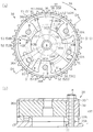
- A is sectional drawing which shows the cross-sectional structure of a variable mechanism about the valve timing control apparatus
- (b) is sectional drawing which shows the cross-sectional structure which followed the DA-DA line of (a).
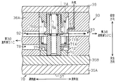
- FIG. 3 is a cross-sectional view showing a cross-sectional structure along the DB-DB line in FIG.
- FIG. 3 is a cross-sectional view showing a cross-sectional structure taken along line DB-DB in FIG. 2A when the lock mechanism is not locked.
- Sectional drawing which shows the cross-section of a variable mechanism.
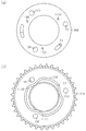
- variable mechanism (a) is a front view showing the front structure of the plate, (b) is a front view showing the front structure of the sprocket.
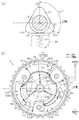
- valve timing control device (a) is a sectional view of the camshaft in the neutral position as viewed from the end side, and (b) is a schematic diagram schematically showing the flow mode of hydraulic oil and air in the variable mechanism while the engine is stopped. Figure.
- valve timing control device controls the valve timing of the intake valve 31.
- an intake camshaft 32 that opens and closes an intake valve 31 and an exhaust camshaft 42 that opens and closes an exhaust valve 41 are rotatably provided on the internal combustion engine 10.
- the intake camshaft 32 is provided with a variable mechanism 30 that changes the valve timing of the intake valve 31.
- the sprocket 35A of the intake camshaft 32, the sprocket 45 of the exhaust camshaft 42, and the sprocket 12 of the crankshaft 11 provided in the variable mechanism 30 are drivingly connected via the timing chain 13.
- the crankshaft 11 rotates, the rotational force is transmitted to the sprockets 35A and 45 via the timing chain 13, and the intake and exhaust camshafts 32 and camshafts 42 rotate.
- the intake valve 31 is urged in the valve closing direction by a valve spring 34 for intake.
- a valve spring 34 for intake.
- the intake valve 31 is pressed by the cam 33 of the camshaft 32 and opens against the elastic force of the valve spring 34.
- the exhaust valve 41 is urged in the valve closing direction by an exhaust valve spring 44.
- the exhaust camshaft 42 rotates, the exhaust valve 41 is pressed by the cam 43 of the camshaft 42 and opens against the elastic force of the valve spring 44.
- an oil pan 21 for storing hydraulic oil is attached to the lower part of the internal combustion engine 10, and is driven by the rotational force of the crankshaft 11 to suck the hydraulic oil in the oil pan 21 and discharge it to the hydraulic oil passage 22.
- An oil pump 20 is provided.
- the hydraulic oil passage 22 is provided with an oil passage control valve 23 that changes the supply / discharge state of the hydraulic oil to / from the hydraulic chambers (advance chamber 51 and retard chamber 52) of the variable mechanism 30.
- the hydraulic oil stored in the oil pan 21 has a function as a hydraulic oil for lubricating each part of the internal combustion engine 10 in addition to a function as a hydraulic oil that generates a hydraulic pressure for driving the variable mechanism 30. Have.
- a starter motor 24 is connected to the crankshaft 11 as an engine starting device for forcibly rotating (cranking) the crankshaft 11 when the internal combustion engine 10 is started. Electric power is supplied from the battery 25 to the starter motor 24.
- crank angle sensor 151 a crank angle sensor 151
- cam angle sensor 152 a cam angle sensor 152
- water temperature sensor 153 is attached to the internal combustion engine 10 in order to detect the engine operating state.
- the crank angle sensor 151 is provided in the vicinity of the crankshaft 11 and detects the crank angle CA and the engine rotation speed.
- the cam angle sensor 152 is provided in the vicinity of the intake camshaft 32 and detects the position of the camshaft 32.
- the water temperature sensor 153 is attached to the main body of the internal combustion engine 10 and detects the temperature of engine cooling water. Signals output from these various sensors are taken into the control unit 150 of the internal combustion engine 10.
- variable mechanism 30 of the valve timing control device will be described with reference to FIG.
- the vane rotor 36 of the variable mechanism 30 includes a boss 36B and three vanes 36A extending from the boss 36B to the outer side in the radial direction of the cam shaft 32.
- the boss 36B is a cam shaft.
- the housing rotor 37 of the variable mechanism 30 has a housing main body 38.
- the sprocket 35A and the plate 35B are fixed to one end side of the housing main body 38 by the bolt B, while the cover 39 is fixed to the other end side by the bolt B. It is fixed.
- the sprocket 35 ⁇ / b> A is connected to the crankshaft 11 through the timing chain 13.
- the housing rotor 37 that is, the cover 39, the housing main body 38, the plate 35 ⁇ / b> B, and the sprocket 35 ⁇ / b> A rotate integrally around the axis C of the cam shaft 32 in the same manner as the vane rotor 36.
- the axis C of the cam shaft 32 that is, the axis C of the housing rotor 37 and the vane rotor 36 extends in the horizontal direction.
- the housing body 38 is formed with three partition walls 38A protruding in the radial direction of the axis C of the housing rotor 37.
- Three storage chambers 50 (a first storage chamber 50A, a second storage chamber 50B, and a third storage chamber 50C) are formed between the adjacent partition walls 38A.
- Each of the storage chambers 50 has a plurality of hydraulic chambers, that is, advance chambers 51 (first advance chamber 51A, second advance chamber 51B, and third advance chamber 51C) and each advance chamber 51 by each vane 36A.
- a retarding chamber 52 (a first retarding chamber 52A, a second retarding chamber 52B, and a third retarding chamber 52C) is defined.
- each advance chamber 51 is located behind the vane 36A in the rotational direction RA of the cam shaft 32.
- each retarded angle chamber 52 is located in front of the vane 36A in the rotational direction RA of the cam shaft 32.
- the vane rotor 36 has an advance oil passage 60A through which hydraulic oil supplied to each advance chamber 51 and hydraulic oil discharged from each advance chamber 51 flows. It is provided in such a manner that it extends toward the center C.
- the vane rotor 36 has a retard oil passage 60 ⁇ / b> B through which hydraulic oil supplied to each retard chamber 52 and hydraulic oil discharged from each retard chamber 52 circulates from each retard chamber 52 to the camshaft 32. It is provided in such a manner that it extends toward the axis C.
- the hydraulic oil is supplied to each advance chamber 51 through each advance oil passage 60A, while the hydraulic oil is discharged from each retard chamber 52 through each retard oil passage 60B, whereby the vane rotor 36 is moved to the housing rotor 37.
- the camshaft 32 rotates in the advance direction, that is, in the rotation direction RA of the cam shaft 32.
- the valve timing is advanced.
- the vane rotor 36 rotates in the rotation direction RA and the vane 36A in each storage chamber 50 comes into contact with the partition wall 38A, so that the valve timing becomes the most advanced angle phase.
- each retarded angle chamber 52 The hydraulic oil is supplied to each retarded angle chamber 52 through each retarded oil passage 60B, while the hydraulic oil is discharged from each advanced chamber 51 through each advanced oil passage 60A, whereby the vane rotor 36 is moved to the housing rotor 37.
- the vane rotor 36 rotates on the retard side, that is, in the direction opposite to the rotational direction RA of the cam shaft 32.
- the valve timing is retarded.
- the vane rotor 36 rotates in the direction opposite to the rotation direction RA, and each vane 36A in each storage chamber 50 comes into contact with the partition wall 38A, so that the valve timing becomes the most retarded phase.
- valve timing control device includes lock mechanisms 70 and 80 for locking the valve timing at an intermediate phase that is a phase between the most advanced angle phase and the most retarded angle phase. 36A and the vane 36A in the second storage chamber 50B.
- the accommodation hole 72 formed inside the vane 36A is provided with a lock pin 71A and an auxiliary pin 71B each formed in a cylindrical shape.
- the auxiliary pin 71B is externally fitted to the lock pin 71A so as to be able to reciprocate.
- the lock pin 71A is formed with a flange 79 on which the auxiliary pin 71B can abut.
- the upper side of the accommodation hole 72 is closed by a cylindrical spring guide bush 74.
- the spring guide bush 74 is inserted and supported by a lock pin 71A.
- a ring bush 75 is provided below the lock pin 71A.
- a main spring 76A for urging the lock pin 71A in the direction of the plate 35B (protruding direction) is provided on the inner peripheral portion of the lock pin 71A, and the auxiliary spring 71B is provided between the spring guide bush 74 and the auxiliary pin 71B.
- An auxiliary spring 76B that biases the pin 71B in the protruding direction is provided.
- a release chamber 77 is defined in the accommodation hole 72 by an inner wall thereof, a lock pin 71A, an auxiliary pin 71B, and a ring bush 75.
- the release chamber 77 is connected to a release oil passage 78 to which hydraulic oil for displacing the auxiliary pin 71B in the direction of the spring guide bush 74 (accommodating direction) against the biasing force of the auxiliary spring 76B is supplied. .
- the lock groove 73 provided in the plate 35B is provided with two grooves having different depths, that is, the lower groove 73A having a relatively large depth and the lower groove 73A on the retard side, and having a relatively small depth.
- the upper groove 73B is used.
- the advance angle inner wall 73C which is the advance angle side end of the lower groove 73A, has the valve timing at an intermediate phase when the lock pin 71A moves in the protruding direction and the lock pin 71A contacts the advance angle inner wall 73C. So that position is set.
- the lock mechanism 70 restricts the valve timing from changing to the advance side. Since the other lock mechanism 80 has the same configuration as the lock mechanism 70 described above, the description thereof is omitted, but the lock mechanism 80 is different in that the valve timing is restricted from changing to the retard side. The valve timing is locked in the intermediate phase by the cooperation of the lock mechanism 70 and the lock mechanism 80.
- the valve timing control device drives the lock mechanisms 70 and 80 so that the valve timing is locked to an intermediate phase when the engine is stopped.
- the hydraulic oil is discharged from each advance chamber 51 and each retard chamber 52.
- the state of the most retarded phase is maintained.
- the vane rotor 36 rotates in the advance direction with respect to the housing rotor 37 due to the fluctuation of the cam torque when the engine is started.
- the valve timing can be locked at an intermediate phase.
- the valve timing control device includes each advance chamber 51 and each retard chamber 51 in order to quickly discharge the hydraulic oil from each advance chamber 51 and each retard chamber 52 when the engine is stopped.
- An air release mechanism 90 that introduces external air into the corner chamber 52 is provided.
- the atmosphere opening mechanism 90 includes an opening passage 91 that communicates the accommodation hole 72 and the outside, and an advance chamber opening passage 92 that communicates the accommodation hole 72 and the third advance chamber 51C. And a retard chamber opening passage 93 that communicates the receiving hole 72 with the third retard chamber 52C.
- the auxiliary pin 71 ⁇ / b> B, the auxiliary spring 76 ⁇ / b> B, the release chamber 77, and the release oil passage 78 described above also function as a part of the atmosphere release mechanism 90.
- Air is introduced from the outside into the second advance chamber 51B and the second retard chamber 52B through the atmosphere release mechanism 90.
- the second retard chamber 52B and the third retard chamber 52C function as open chambers.
- the second advance chamber 51B and the second retard chamber 52B defined by the vane 36A provided with the atmosphere release mechanism 90 are perpendicular to the axis C of the cam shaft 32.
- air is directly introduced into the hydraulic chambers 51B and 52B from the atmospheric release mechanism 90, and the hydraulic oil in the hydraulic chambers 51B and 52B is advanced oil. Since it flows to the axis C side of the cam shaft 32 through the path 60A and the retarded oil path 60B, it is quickly discharged.
- valve timing is changed to the intermediate phase by utilizing the fact that the vane rotor 36 swings toward the advance side or the retard side due to the fluctuation of the cam torque when starting the engine. Accordingly, the valve timing can be locked to the intermediate phase by advancing or retarding the angle.
- a one-dot chain line in the figure is a horizontal line passing through the axis C of the cam shaft 32.
- each of the hydraulic chambers 51A and 52A is directly connected. Air is not introduced into the air. Accordingly, when the rotation of the vane rotor 36 is stopped in a state where the hydraulic chambers 51A and 52A are positioned vertically above the axis C of the cam shaft 32, the hydraulic oil is discharged from the hydraulic chambers 51A and 52A. Hateful. Therefore, it becomes difficult to lock the valve timing to the intermediate phase by using the swing of the vane rotor 36 as described above.
- variable mechanism 30 has a communication path for introducing the air introduced into the second retardation chamber 52B and the third retardation chamber 52C by the atmospheric release mechanisms 90 into the first retardation chamber 52A. 100 is provided.
- FIG. 6A shows the surface of the plate 35B on the side assembled to the housing body 38.
- FIG. 6B shows a surface of the sprocket 35 ⁇ / b> A that is assembled to the housing main body 38.
- the plate 35B has a first opening 110A, a second opening 110B, and three bolt holes 120 for fastening the third opening 110C and the bolt B. ing.
- the first opening 110A is located on the most advanced side of the first retarding chamber 52A
- the second opening 110B is the most advanced of the second retarding chamber 52B
- the third opening 110C is located on the most advanced side of the third retardation chamber 52C.
- the sprocket 35A is formed with three bolt holes 130 for fastening the bolt B, and an annular communication path 100 is formed on the joint surface with the plate 35B. Is formed.
- the communication path 100 and the retarded angle chambers 52A to 52C are in communication with each other through the openings 110A to 110C. That is, the retard chambers 52A to 52C are communicated through the communication path 100.
- FIG. 7B shows a state in which the valve timing is the most retarded phase and the rotation of the vane rotor 36 is stopped.
- the camshaft 32 is provided with three cams 33 corresponding to the respective cylinders provided in the internal combustion engine.
- the profiles of these cams 33 are set so that the apex of the cam nose 33A is positioned around the cam shaft 32 at 120 ° intervals when viewed from the end side of the cam shaft 32.
- lifters 140 for opening and closing the intake valve 31 are in contact with these cams 33 by the urging force of the valve spring 34.
- FIG. 7B shows the state of the vane rotor 36 and the housing rotor 37 when the rotation of the camshaft 32 stops at the neutral position.
- each of the hydraulic chambers 51A, 52A is positioned vertically above the horizontal line, while each of the hydraulic chambers 51B, 52B, 51C, 52C is more than the hydraulic chambers 51A, 52A. Is also located below. Further, in this case, the second opening 110B is located above the horizontal line in the vertical direction. In other words, when the cam shaft 32 is in its neutral position, the profile of the cam 33 is set so that the second opening 110B is positioned above the horizontal line in the vertical direction.
- the cam shaft 32 in which the profile of the cam 33 is set based on the relationship with the stop position of the vane rotor 36 that is in the most retarded phase with respect to the housing rotor 37 is used as the stop phase adjusting mechanism. Equivalent to.
- the air introduced into the second retardation chamber 52B and the third retardation chamber 52C by the atmosphere release mechanism 90 the air introduced into the second retardation chamber 52B is transferred to the second opening chamber 52B.
- 110B is introduced into the first retarding chamber 52A through the communication passage 100.
- the air introduced into the third retarding chamber 52C is introduced into the first retarding chamber 52A through the communication path 100 from the third opening 110C.
- the hydraulic oil flows from the first retarding chamber 52A through the retarding oil passage 60B.
- the cam shaft 32 flows toward the axis C side and is discharged.
- the first retarding chamber 52A communicated with the retarding chambers 52B and 52C, which are open chambers, through the communication path 100 functions as an introduction chamber.
- valve timing when the valve timing is not locked to the intermediate phase when the engine is stopped, the valve timing is often relatively retarded due to the influence of cam friction or the like. More specifically, in such a case, the valve timing is most often the most retarded phase.
- each retarding chamber 52 if the hydraulic oil in each retarding chamber 52 is not properly discharged, each retarding chamber 52 is in an oil-tight state. Therefore, when the vane rotor 36 rotates with the rotation of the camshaft 32, the vane rotor 36 and The housing rotor 37 rotates in conjunction with it. That is, both rotating bodies rotate together.
- the cam shaft 32 is in the neutral position under the state where the valve timing is the most retarded phase.
- a space can be formed in the vicinity of the second opening 110B by setting the profile of the cam 33 so that the second opening 110B is positioned vertically above the axis C of the camshaft 32.
- each retarding chamber 52 is difficult to be discharged in a state where each retarding chamber 52 is positioned below the horizon in the vertical direction.
- the retard chambers 52B and 52C defined by the vane 36A provided with the air release mechanism 90 are such that the vane rotor 36 and the housing rotor 37 rotate after the engine is started so that the retard chambers 52B and 52C are vertically above the horizontal line. Since the air is directly introduced by the atmospheric release mechanism 90, the remaining hydraulic oil is quickly discharged.
- the first retarding chamber 52A defined by the vane 36A not provided with the atmosphere release mechanism 90 is configured such that the vane rotor 36 and the housing rotor 37 rotate after the engine is started so that the first retarding chamber 52A is horizontal. Even if it is positioned above the vertical direction, since the air is not directly introduced from the outside, the remaining hydraulic oil is difficult to be discharged. Therefore, the hydraulic oil remaining in the first retardation chamber 52A is required to be discharged while the engine is stopped.
- valve timing control device of the present embodiment can quickly discharge the hydraulic oil remaining in the first retardation chamber 52A when the engine is stopped.
- valve timing If the valve timing is not locked to the intermediate phase when the engine is stopped, the valve timing is often gradually retarded. In particular, the demand for expelling the hydraulic oil in each retarded chamber 52 is particularly high. It is as follows.
- the open chambers are the second retard chamber 52B and the third retard chamber 52C, and the introduction chamber is the first retard chamber 52A, so that each retard chamber is an open chamber by the atmospheric release mechanism 90.
- the introduction chamber is the first retard chamber 52A, so that each retard chamber is an open chamber by the atmospheric release mechanism 90.
- the first retarding chamber 52A which is a retarding chamber different from each retarding chamber 52B and 52C, through the communication path 100.
- the hydraulic oil in the introduction chamber that is, the first retard chamber 52A is quickly discharged through the retard oil passage 60B. Can do.
- the lock mechanism that locks the valve timing not in the intermediate phase but in the most retarded phase the necessity of discharging the hydraulic oil in each advance chamber 51 and each retard chamber 52 is reduced.
- the lock mechanisms 70 and 80 cooperate with each other to lock the valve timing at an intermediate phase between the most advanced angle phase and the most retarded angle phase. Therefore, it is necessary to swing the vane rotor 36, that is, each advance chamber. The necessity to discharge the hydraulic oil of 51 and each retardation chamber 52 becomes high.
- the valve timing control device of the present embodiment can quickly discharge the hydraulic oil from each retard chamber 52 when the valve timing stops at the most retarded phase, for example, and thus the above-described (1) and (2) This effect can be made more remarkable.
- the retarded angle chambers 52A to 52C are communicated with each other by the openings 110A to 110C provided in the plate 35B and the annular communication passage 100 formed in the sprocket 35A. Therefore, a communication passage that communicates the first retardation chamber 52A and the second retardation chamber 52B and a communication passage that communicates the first retardation chamber 52A and the third retardation chamber 52C are provided separately. Compared with the configuration, the configuration of the communication path can be simplified.
- valve timing control apparatus is not limited to the configuration exemplified in the above-described embodiment, and can be implemented as, for example, the following form obtained by appropriately modifying this embodiment.
- the second opening 110B can be provided in the vane rotor 36.
- the valve timing is set to a value other than the most retarded phase by setting the profile of the cam 33 of the cam shaft 32. Even at that time, the second opening 110B can be positioned vertically above the axis C of the cam shaft 32.
- the engine is such that the second opening 110B is positioned vertically above the axis C of the camshaft 32 when the engine is stopped. It is also possible to adjust the stop phase of the housing rotor 37 by driving the starter and rotating the crankshaft 11.
- An example of the engine starting device is a starter motor 24.
- the starter motor 24 is preferably a constant mesh type.
- a motor generator can be mentioned.
- auxiliary machine driven by the crankshaft 11 when the engine is stopped.
- the second opening 110 ⁇ / b> B is perpendicular to the axis C of the camshaft 32 when the engine is stopped. It becomes possible to position it in the upper direction.
- auxiliary machines include a rotary pump driven by a generator and a crankshaft 11, that is, an oil pump 20 and the like.
- the valve timing when the valve timing is not locked to the intermediate phase when the engine is stopped, the valve timing is likely to be the most retarded phase, and the hydraulic oil is appropriately supplied from each retarded chamber 52. If it is not discharged, both rotating bodies will rotate together. Therefore, in the configuration in which the second opening 110B is provided in the vane rotor 36, the second opening 110B is camped as described above in a state where the engine is stopped and the valve timing is the most retarded phase.
- the stop phase of the housing rotor 37 can be adjusted by driving the engine starter so as to be positioned vertically above the axis C of the shaft 32 and rotating the crankshaft 11.
- the auxiliary shaft driven by the crankshaft is used.
- the stop phase of the crankshaft 11 can be controlled to adjust the stop phase of the housing rotor 37.
- the retarding chambers 52A to 52C are communicated with each other through the communication path 100, but the retarding chambers 52B and 52C may not be communicated.
- the retard chambers 52A to 52C are communicated with each other through the communication path 100, but any advance chambers 51 can be communicated with each other through the communication path. Furthermore, it is also possible to communicate the arbitrary retarded angle chambers 52 with each other through the communication path in a state where the arbitrary advance chambers 51 communicate with each other through the communication path. Further, each of the advance chambers 51 and each of the retard chambers 52 may be communicated with each other through a communication path. In this case, it is preferable to suppress a decrease in the operation responsiveness of the valve timing control device, for example, by providing a throttle portion with a relatively small flow area in the communication path.
- the communication path 100 is provided in the plate 35B, but the communication path 100 can be provided in the cover 39 or the vane rotor 36.
- the atmosphere release mechanism 90 communicates all of the second advance chamber 51B, the second retard chamber 52B, the third advance chamber 51C, and the third retard chamber 52C with the outside to each hydraulic chamber 51B, Although air is introduced into 52B, 51C, 52C, one of the hydraulic chambers 51B, 52B and one of the hydraulic chambers 51C, 52C may communicate with the outside.
- the profile of the cam 33 of the cam shaft 32 is set so that the second opening 110B is positioned vertically above the axis C of the cam shaft 32, but the third opening 110C is positioned in the same direction.
- the profile of the cam 33 of the cam shaft 32 can also be set.
- the lock pin 71A moves in the axial direction of the vane rotor 36
- the structure can be changed to a structure in which the lock pin 71A moves in the radial direction of the vane rotor 36. That is, the lock pin 71A may be provided on the vane 36A so that the lock pin 71A moves in the radial direction of the vane rotor 36, while the lock groove 73 may be provided at a portion of the housing rotor 37 corresponding to the lock pin 71A.
- the valve timing control device of the above embodiment targets an in-line three-cylinder internal combustion engine in which the cam 33 is disposed so that the apex of the cam nose 33A is positioned every 120 ° around the central axis of the cam shaft 32. did.
- the internal combustion engine to which the valve timing control device according to the present invention is applied is not limited to an in-line three-cylinder internal combustion engine.
- the present invention can be embodied as a valve timing control device for an in-line four-cylinder internal combustion engine. In this case, the neutral position of the cam shaft appears every 90 ° in the rotation direction of the cam shaft.
Landscapes
- Engineering & Computer Science (AREA)
- Mechanical Engineering (AREA)
- General Engineering & Computer Science (AREA)
- Valve Device For Special Equipments (AREA)
- Valve-Gear Or Valve Arrangements (AREA)
Abstract
Description
・第2の開口110Bがカム軸32の軸心Cよりも鉛直方向上方に位置するようにカム軸32のカム33のプロフィールを設定したが、第3の開口110Cが同方向に位置するようにカム軸32のカム33のプロフィールを設定することもできる。
・ロック機構70,80の構造として、ロックピン71Aがベーンロータ36の軸方向に移動する構造を採用したが、ロックピン71Aがベーンロータ36の径方向に移動する構造に変更することもできる。すなわち、ロックピン71Aがベーンロータ36の径方向に移動するようにロックピン71Aをベーン36Aに設ける一方、ロックピン71Aと対応するハウジングロータ37の部位にロック溝73を設けることもできる。
Claims (9)
- クランク軸と連動する第1の回転体及びカム軸と連動して前記第1の回転体と同一の軸心を中心に回転する第2の回転体の相対回転位相を、両回転体により画成された複数の油圧室の油圧に基づいて変更する可変機構と、
前記相対回転位相を特定位相にロックするロック機構と、
前記複数の油圧室から前記軸心に向かって延伸して前記複数の油圧室からそれぞれ作動油を排出する複数の排出路と
を備える、内燃機関のバルブタイミング制御装置において、
前記複数の油圧室の一つである開放室を機関停止状態のときに外部に連通して同開放室に空気を導入する大気開放機構と、
前記複数の油圧室のうち前記開放室とは異なる油圧室である導入室を前記開放室に連通する連通路であって、前記開放室に開口する開口を有する連通路と、
機関停止状態のときに前記連通路の前記開口が前記軸心よりも鉛直方向上方に位置するように、前記両回転体の少なくとも一方の停止位相を調節する停止位相調節機構と
を備えることを特徴とする内燃機関のバルブタイミング制御装置。 - 前記開放室及び前記導入室はバルブタイミングを遅角させるための各別の遅角室である
ことを特徴とする請求項1に記載の内燃機関のバルブタイミング制御装置。 - 前記開口は前記第1の回転体に設けられ、
前記停止位相調節機構は前記カム軸を含み、同カム軸に設けられるカムは、前記第2の回転体が前記第1の回転体に対して最遅角位相にある状態のもとカムからカム軸に作用するトルクが最も小さくなるときに前記開口が前記軸心よりも鉛直方向上方に位置するように、そのプロフィールが設定されてなる
ことを特徴とする請求項2に記載の内燃機関のバルブタイミング制御装置。 - 前記開口は前記第2の回転体に設けられ、
前記停止位相調節機構は前記カム軸を含み、同カム軸に設けられるカムは、カムからカム軸に作用するトルクが最も小さくなるときに前記開口が前記軸心よりも鉛直方向上方に位置するように、そのプロフィールが設定されてなる
ことを特徴とする請求項1又は2に記載の内燃機関のバルブタイミング制御装置。 - 前記開口は前記第1の回転体に設けられ、
前記停止位相調節機構は、機関停止状態のときに、前記開口が前記軸心よりも鉛直方向上方に位置するように機関始動装置を駆動し前記クランク軸を回転させて前記第1の回転体の停止位相を調節する
ことを特徴とする請求項1又は2に記載の内燃機関のバルブタイミング制御装置。 - 前記開口は前記第2の回転体に設けられ、
前記停止位相調節機構は、機関停止状態であって前記第2の回転体が前記第1の回転体に対して最遅角位相にある状態のときに、前記開口が前記軸心よりも鉛直方向上方に位置するように機関始動装置を駆動し前記クランク軸を回転させて前記第1の回転体の停止位相を調節する
ことを特徴とする請求項2に記載の内燃機関のバルブタイミング制御装置。 - 前記開口は前記第1の回転体に設けられ、
前記停止位相調節機構は、機関停止状態のときに前記開口が前記軸心よりも鉛直方向上方に位置するように、機関停止に際して、前記クランク軸により駆動される補機の負荷を制御して前記第1の回転体の停止位相を調節する
ことを特徴とする請求項1又は2に記載の内燃機関のバルブタイミング制御装置。 - 前記開口は前記第2の回転体に設けられ、
前記停止位相調節機構は、機関停止状態であって前記第2の回転体が第1の回転体に対して最遅角位相にある状態のときに前記開口が前記軸心よりも鉛直方向上方に位置するように、機関停止に際して、前記クランク軸により駆動される補機の負荷を制御して前記第1の回転体の停止位相を調節する
ことを特徴とする請求項2に記載の内燃機関のバルブタイミング制御装置。 - 前記特定位相は最進角位相と最遅角位相との間の中間位相である
ことを特徴とする請求項1~8のいずれか一項に記載の内燃機関のバルブタイミング制御装置。
Priority Applications (4)
| Application Number | Priority Date | Filing Date | Title |
|---|---|---|---|
| JP2012519814A JP5288050B2 (ja) | 2011-05-18 | 2011-05-18 | 内燃機関のバルブタイミング制御装置 |
| CN201180007697.XA CN102892978B (zh) | 2011-05-18 | 2011-05-18 | 用于内燃发动机的气门正时控制器 |
| US13/515,708 US8578900B2 (en) | 2011-05-18 | 2011-05-18 | Valve timing controller for internal combustion engine |
| PCT/JP2011/061450 WO2012157098A1 (ja) | 2011-05-18 | 2011-05-18 | 内燃機関のバルブタイミング制御装置 |
Applications Claiming Priority (1)
| Application Number | Priority Date | Filing Date | Title |
|---|---|---|---|
| PCT/JP2011/061450 WO2012157098A1 (ja) | 2011-05-18 | 2011-05-18 | 内燃機関のバルブタイミング制御装置 |
Publications (1)
| Publication Number | Publication Date |
|---|---|
| WO2012157098A1 true WO2012157098A1 (ja) | 2012-11-22 |
Family
ID=47176461
Family Applications (1)
| Application Number | Title | Priority Date | Filing Date |
|---|---|---|---|
| PCT/JP2011/061450 Ceased WO2012157098A1 (ja) | 2011-05-18 | 2011-05-18 | 内燃機関のバルブタイミング制御装置 |
Country Status (4)
| Country | Link |
|---|---|
| US (1) | US8578900B2 (ja) |
| JP (1) | JP5288050B2 (ja) |
| CN (1) | CN102892978B (ja) |
| WO (1) | WO2012157098A1 (ja) |
Families Citing this family (3)
| Publication number | Priority date | Publication date | Assignee | Title |
|---|---|---|---|---|
| JP5648742B2 (ja) * | 2011-05-17 | 2015-01-07 | トヨタ自動車株式会社 | 内燃機関の可変動弁装置 |
| JP5966781B2 (ja) * | 2012-09-06 | 2016-08-10 | アイシン精機株式会社 | 弁開閉時期制御システム |
| DE102013207615B4 (de) * | 2013-04-26 | 2021-05-12 | Schaeffler Technologies AG & Co. KG | Nockenwellenverstelleinrichtung mit einer Mittenverriegelung |
Citations (4)
| Publication number | Priority date | Publication date | Assignee | Title |
|---|---|---|---|---|
| JPH11241608A (ja) * | 1997-12-24 | 1999-09-07 | Toyota Motor Corp | 内燃機関におけるバルブタイミング調整機構 |
| JP2003314217A (ja) * | 2002-04-23 | 2003-11-06 | Mitsubishi Electric Corp | 内燃機関のバルブタイミング制御装置 |
| JP2010223212A (ja) * | 2009-02-26 | 2010-10-07 | Aisin Seiki Co Ltd | 弁開閉時期制御装置 |
| JP2011085074A (ja) * | 2009-10-15 | 2011-04-28 | Denso Corp | バルブタイミング調整装置 |
Family Cites Families (6)
| Publication number | Priority date | Publication date | Assignee | Title |
|---|---|---|---|---|
| JP2002122009A (ja) | 2000-08-09 | 2002-04-26 | Mitsubishi Electric Corp | バルブタイミング調整装置 |
| JP4425155B2 (ja) * | 2004-03-12 | 2010-03-03 | 日立オートモティブシステムズ株式会社 | 内燃機関のバルブタイミング制御装置 |
| JP5376227B2 (ja) * | 2009-05-25 | 2013-12-25 | アイシン精機株式会社 | 弁開閉時期制御装置 |
| JP4752953B2 (ja) * | 2009-06-10 | 2011-08-17 | 株式会社デンソー | バルブタイミング調整装置 |
| JP2011185100A (ja) | 2010-03-04 | 2011-09-22 | Denso Corp | 内燃機関のバルブタイミング変更装置 |
| JP2012002081A (ja) | 2010-06-14 | 2012-01-05 | Toyota Motor Corp | 内燃機関の可変動弁装置 |
-
2011
- 2011-05-18 WO PCT/JP2011/061450 patent/WO2012157098A1/ja not_active Ceased
- 2011-05-18 JP JP2012519814A patent/JP5288050B2/ja not_active Expired - Fee Related
- 2011-05-18 CN CN201180007697.XA patent/CN102892978B/zh not_active Expired - Fee Related
- 2011-05-18 US US13/515,708 patent/US8578900B2/en not_active Expired - Fee Related
Patent Citations (4)
| Publication number | Priority date | Publication date | Assignee | Title |
|---|---|---|---|---|
| JPH11241608A (ja) * | 1997-12-24 | 1999-09-07 | Toyota Motor Corp | 内燃機関におけるバルブタイミング調整機構 |
| JP2003314217A (ja) * | 2002-04-23 | 2003-11-06 | Mitsubishi Electric Corp | 内燃機関のバルブタイミング制御装置 |
| JP2010223212A (ja) * | 2009-02-26 | 2010-10-07 | Aisin Seiki Co Ltd | 弁開閉時期制御装置 |
| JP2011085074A (ja) * | 2009-10-15 | 2011-04-28 | Denso Corp | バルブタイミング調整装置 |
Also Published As
| Publication number | Publication date |
|---|---|
| CN102892978A (zh) | 2013-01-23 |
| JPWO2012157098A1 (ja) | 2014-07-31 |
| CN102892978B (zh) | 2014-10-08 |
| US8578900B2 (en) | 2013-11-12 |
| JP5288050B2 (ja) | 2013-09-11 |
| US20130032108A1 (en) | 2013-02-07 |
Similar Documents
| Publication | Publication Date | Title |
|---|---|---|
| JPH10212911A (ja) | 内燃機関のバルブタイミング可変機構 | |
| JP2005061261A (ja) | 内燃機関の可変動弁装置 | |
| JP2015194131A (ja) | エンジンの制御装置 | |
| JP2011185100A (ja) | 内燃機関のバルブタイミング変更装置 | |
| JP2002227621A (ja) | 内燃機関用バルブタイミング調整装置 | |
| US6260526B1 (en) | Valve movement control system of an internal combustion engine | |
| JP5288050B2 (ja) | 内燃機関のバルブタイミング制御装置 | |
| JP4803251B2 (ja) | 内燃機関用バルブタイミング調整装置 | |
| JP2010209780A (ja) | 内燃機関の可変動弁機構 | |
| EP2881620B1 (en) | Variable Valve Timing Control Apparatus | |
| JP2007292027A (ja) | 弁開閉時期制御装置 | |
| JP2010242714A (ja) | 内燃機関の可変動弁装置 | |
| JP2015034501A (ja) | 弁開閉時期制御装置 | |
| JP2015025440A (ja) | 弁開閉時期制御装置 | |
| CN102808669B (zh) | 配气正时变更装置 | |
| JP5282850B2 (ja) | 内燃機関の可変動弁装置 | |
| JP5288044B2 (ja) | 内燃機関の可変動弁装置 | |
| JP5288043B2 (ja) | 内燃機関の可変動弁装置 | |
| JP2010242532A (ja) | 内燃機関の可変動弁装置 | |
| JP4627294B2 (ja) | 内燃機関のバルブタイミング変更装置およびカムキャップ | |
| JP2012002081A (ja) | 内燃機関の可変動弁装置 | |
| JP2004245074A (ja) | エンジンの可変動弁装置 | |
| JP2016079899A (ja) | 内燃機関の可変バルブタイミング制御装置 | |
| JP3846407B2 (ja) | エンジンの可変バルブタイミング装置 | |
| JP2019132201A (ja) | 弁開閉時期制御装置 |
Legal Events
| Date | Code | Title | Description |
|---|---|---|---|
| WWE | Wipo information: entry into national phase |
Ref document number: 201180007697.X Country of ref document: CN |
|
| ENP | Entry into the national phase |
Ref document number: 2012519814 Country of ref document: JP Kind code of ref document: A |
|
| WWE | Wipo information: entry into national phase |
Ref document number: 13515708 Country of ref document: US |
|
| 121 | Ep: the epo has been informed by wipo that ep was designated in this application |
Ref document number: 11865499 Country of ref document: EP Kind code of ref document: A1 |
|
| NENP | Non-entry into the national phase |
Ref country code: DE |
|
| 122 | Ep: pct application non-entry in european phase |
Ref document number: 11865499 Country of ref document: EP Kind code of ref document: A1 |