WO2012153423A1 - 多種燃料内燃機関の制御システム - Google Patents
多種燃料内燃機関の制御システム Download PDFInfo
- Publication number
- WO2012153423A1 WO2012153423A1 PCT/JP2011/060987 JP2011060987W WO2012153423A1 WO 2012153423 A1 WO2012153423 A1 WO 2012153423A1 JP 2011060987 W JP2011060987 W JP 2011060987W WO 2012153423 A1 WO2012153423 A1 WO 2012153423A1
- Authority
- WO
- WIPO (PCT)
- Prior art keywords
- amount
- fuel
- cylinder group
- internal combustion
- combustion engine
- Prior art date
- Legal status (The legal status is an assumption and is not a legal conclusion. Google has not performed a legal analysis and makes no representation as to the accuracy of the status listed.)
- Ceased
Links
Images


Classifications
-
- F—MECHANICAL ENGINEERING; LIGHTING; HEATING; WEAPONS; BLASTING
- F02—COMBUSTION ENGINES; HOT-GAS OR COMBUSTION-PRODUCT ENGINE PLANTS
- F02D—CONTROLLING COMBUSTION ENGINES
- F02D41/00—Electrical control of supply of combustible mixture or its constituents
- F02D41/0025—Controlling engines characterised by use of non-liquid fuels, pluralities of fuels, or non-fuel substances added to the combustible mixtures
-
- F—MECHANICAL ENGINEERING; LIGHTING; HEATING; WEAPONS; BLASTING
- F01—MACHINES OR ENGINES IN GENERAL; ENGINE PLANTS IN GENERAL; STEAM ENGINES
- F01N—GAS-FLOW SILENCERS OR EXHAUST APPARATUS FOR MACHINES OR ENGINES IN GENERAL; GAS-FLOW SILENCERS OR EXHAUST APPARATUS FOR INTERNAL-COMBUSTION ENGINES
- F01N13/00—Exhaust or silencing apparatus characterised by constructional features
- F01N13/009—Exhaust or silencing apparatus characterised by constructional features having two or more separate purifying devices arranged in series
-
- F—MECHANICAL ENGINEERING; LIGHTING; HEATING; WEAPONS; BLASTING
- F01—MACHINES OR ENGINES IN GENERAL; ENGINE PLANTS IN GENERAL; STEAM ENGINES
- F01N—GAS-FLOW SILENCERS OR EXHAUST APPARATUS FOR MACHINES OR ENGINES IN GENERAL; GAS-FLOW SILENCERS OR EXHAUST APPARATUS FOR INTERNAL-COMBUSTION ENGINES
- F01N13/00—Exhaust or silencing apparatus characterised by constructional features
- F01N13/011—Exhaust or silencing apparatus characterised by constructional features having two or more purifying devices arranged in parallel
-
- F—MECHANICAL ENGINEERING; LIGHTING; HEATING; WEAPONS; BLASTING
- F02—COMBUSTION ENGINES; HOT-GAS OR COMBUSTION-PRODUCT ENGINE PLANTS
- F02D—CONTROLLING COMBUSTION ENGINES
- F02D19/00—Controlling engines characterised by their use of non-liquid fuels, pluralities of fuels, or non-fuel substances added to the combustible mixtures
- F02D19/06—Controlling engines characterised by their use of non-liquid fuels, pluralities of fuels, or non-fuel substances added to the combustible mixtures peculiar to engines working with pluralities of fuels, e.g. alternatively with light and heavy fuel oil, other than engines indifferent to the fuel consumed
- F02D19/0602—Control of components of the fuel supply system
- F02D19/0607—Control of components of the fuel supply system to adjust the fuel mass or volume flow
- F02D19/061—Control of components of the fuel supply system to adjust the fuel mass or volume flow by controlling fuel injectors
-
- F—MECHANICAL ENGINEERING; LIGHTING; HEATING; WEAPONS; BLASTING
- F02—COMBUSTION ENGINES; HOT-GAS OR COMBUSTION-PRODUCT ENGINE PLANTS
- F02D—CONTROLLING COMBUSTION ENGINES
- F02D19/00—Controlling engines characterised by their use of non-liquid fuels, pluralities of fuels, or non-fuel substances added to the combustible mixtures
- F02D19/06—Controlling engines characterised by their use of non-liquid fuels, pluralities of fuels, or non-fuel substances added to the combustible mixtures peculiar to engines working with pluralities of fuels, e.g. alternatively with light and heavy fuel oil, other than engines indifferent to the fuel consumed
- F02D19/0639—Controlling engines characterised by their use of non-liquid fuels, pluralities of fuels, or non-fuel substances added to the combustible mixtures peculiar to engines working with pluralities of fuels, e.g. alternatively with light and heavy fuel oil, other than engines indifferent to the fuel consumed characterised by the type of fuels
- F02D19/0642—Controlling engines characterised by their use of non-liquid fuels, pluralities of fuels, or non-fuel substances added to the combustible mixtures peculiar to engines working with pluralities of fuels, e.g. alternatively with light and heavy fuel oil, other than engines indifferent to the fuel consumed characterised by the type of fuels at least one fuel being gaseous, the other fuels being gaseous or liquid at standard conditions
- F02D19/0647—Controlling engines characterised by their use of non-liquid fuels, pluralities of fuels, or non-fuel substances added to the combustible mixtures peculiar to engines working with pluralities of fuels, e.g. alternatively with light and heavy fuel oil, other than engines indifferent to the fuel consumed characterised by the type of fuels at least one fuel being gaseous, the other fuels being gaseous or liquid at standard conditions the gaseous fuel being liquefied petroleum gas [LPG], liquefied natural gas [LNG], compressed natural gas [CNG] or dimethyl ether [DME]
-
- F—MECHANICAL ENGINEERING; LIGHTING; HEATING; WEAPONS; BLASTING
- F02—COMBUSTION ENGINES; HOT-GAS OR COMBUSTION-PRODUCT ENGINE PLANTS
- F02D—CONTROLLING COMBUSTION ENGINES
- F02D41/00—Electrical control of supply of combustible mixture or its constituents
- F02D41/008—Controlling each cylinder individually
- F02D41/0082—Controlling each cylinder individually per groups or banks
-
- F—MECHANICAL ENGINEERING; LIGHTING; HEATING; WEAPONS; BLASTING
- F02—COMBUSTION ENGINES; HOT-GAS OR COMBUSTION-PRODUCT ENGINE PLANTS
- F02D—CONTROLLING COMBUSTION ENGINES
- F02D41/00—Electrical control of supply of combustible mixture or its constituents
- F02D41/008—Controlling each cylinder individually
- F02D41/0087—Selective cylinder activation, i.e. partial cylinder operation
-
- F—MECHANICAL ENGINEERING; LIGHTING; HEATING; WEAPONS; BLASTING
- F02—COMBUSTION ENGINES; HOT-GAS OR COMBUSTION-PRODUCT ENGINE PLANTS
- F02D—CONTROLLING COMBUSTION ENGINES
- F02D41/00—Electrical control of supply of combustible mixture or its constituents
- F02D41/02—Circuit arrangements for generating control signals
- F02D41/021—Introducing corrections for particular conditions exterior to the engine
- F02D41/0235—Introducing corrections for particular conditions exterior to the engine in relation with the state of the exhaust gas treating apparatus
- F02D41/024—Introducing corrections for particular conditions exterior to the engine in relation with the state of the exhaust gas treating apparatus to increase temperature of the exhaust gas treating apparatus
- F02D41/025—Introducing corrections for particular conditions exterior to the engine in relation with the state of the exhaust gas treating apparatus to increase temperature of the exhaust gas treating apparatus by changing the composition of the exhaust gas, e.g. for exothermic reaction on exhaust gas treating apparatus
-
- F—MECHANICAL ENGINEERING; LIGHTING; HEATING; WEAPONS; BLASTING
- F02—COMBUSTION ENGINES; HOT-GAS OR COMBUSTION-PRODUCT ENGINE PLANTS
- F02D—CONTROLLING COMBUSTION ENGINES
- F02D41/00—Electrical control of supply of combustible mixture or its constituents
- F02D41/02—Circuit arrangements for generating control signals
- F02D41/021—Introducing corrections for particular conditions exterior to the engine
- F02D41/0235—Introducing corrections for particular conditions exterior to the engine in relation with the state of the exhaust gas treating apparatus
- F02D41/027—Introducing corrections for particular conditions exterior to the engine in relation with the state of the exhaust gas treating apparatus to purge or regenerate the exhaust gas treating apparatus
- F02D41/0275—Introducing corrections for particular conditions exterior to the engine in relation with the state of the exhaust gas treating apparatus to purge or regenerate the exhaust gas treating apparatus the exhaust gas treating apparatus being a NOx trap or adsorbent
-
- F—MECHANICAL ENGINEERING; LIGHTING; HEATING; WEAPONS; BLASTING
- F01—MACHINES OR ENGINES IN GENERAL; ENGINE PLANTS IN GENERAL; STEAM ENGINES
- F01N—GAS-FLOW SILENCERS OR EXHAUST APPARATUS FOR MACHINES OR ENGINES IN GENERAL; GAS-FLOW SILENCERS OR EXHAUST APPARATUS FOR INTERNAL-COMBUSTION ENGINES
- F01N3/00—Exhaust or silencing apparatus having means for purifying, rendering innocuous, or otherwise treating exhaust
- F01N3/08—Exhaust or silencing apparatus having means for purifying, rendering innocuous, or otherwise treating exhaust for rendering innocuous
- F01N3/10—Exhaust or silencing apparatus having means for purifying, rendering innocuous, or otherwise treating exhaust for rendering innocuous by thermal or catalytic conversion of noxious components of exhaust
- F01N3/101—Three-way catalysts
-
- F—MECHANICAL ENGINEERING; LIGHTING; HEATING; WEAPONS; BLASTING
- F02—COMBUSTION ENGINES; HOT-GAS OR COMBUSTION-PRODUCT ENGINE PLANTS
- F02D—CONTROLLING COMBUSTION ENGINES
- F02D19/00—Controlling engines characterised by their use of non-liquid fuels, pluralities of fuels, or non-fuel substances added to the combustible mixtures
- F02D19/06—Controlling engines characterised by their use of non-liquid fuels, pluralities of fuels, or non-fuel substances added to the combustible mixtures peculiar to engines working with pluralities of fuels, e.g. alternatively with light and heavy fuel oil, other than engines indifferent to the fuel consumed
- F02D19/0663—Details on the fuel supply system, e.g. tanks, valves, pipes, pumps, rails, injectors or mixers
- F02D19/0686—Injectors
- F02D19/0692—Arrangement of multiple injectors per combustion chamber
-
- F—MECHANICAL ENGINEERING; LIGHTING; HEATING; WEAPONS; BLASTING
- F02—COMBUSTION ENGINES; HOT-GAS OR COMBUSTION-PRODUCT ENGINE PLANTS
- F02D—CONTROLLING COMBUSTION ENGINES
- F02D2200/00—Input parameters for engine control
- F02D2200/02—Input parameters for engine control the parameters being related to the engine
- F02D2200/08—Exhaust gas treatment apparatus parameters
- F02D2200/0806—NOx storage amount, i.e. amount of NOx stored on NOx trap
-
- F—MECHANICAL ENGINEERING; LIGHTING; HEATING; WEAPONS; BLASTING
- F02—COMBUSTION ENGINES; HOT-GAS OR COMBUSTION-PRODUCT ENGINE PLANTS
- F02D—CONTROLLING COMBUSTION ENGINES
- F02D41/00—Electrical control of supply of combustible mixture or its constituents
- F02D41/0025—Controlling engines characterised by use of non-liquid fuels, pluralities of fuels, or non-fuel substances added to the combustible mixtures
- F02D41/0027—Controlling engines characterised by use of non-liquid fuels, pluralities of fuels, or non-fuel substances added to the combustible mixtures the fuel being gaseous
-
- Y—GENERAL TAGGING OF NEW TECHNOLOGICAL DEVELOPMENTS; GENERAL TAGGING OF CROSS-SECTIONAL TECHNOLOGIES SPANNING OVER SEVERAL SECTIONS OF THE IPC; TECHNICAL SUBJECTS COVERED BY FORMER USPC CROSS-REFERENCE ART COLLECTIONS [XRACs] AND DIGESTS
- Y02—TECHNOLOGIES OR APPLICATIONS FOR MITIGATION OR ADAPTATION AGAINST CLIMATE CHANGE
- Y02T—CLIMATE CHANGE MITIGATION TECHNOLOGIES RELATED TO TRANSPORTATION
- Y02T10/00—Road transport of goods or passengers
- Y02T10/10—Internal combustion engine [ICE] based vehicles
- Y02T10/12—Improving ICE efficiencies
-
- Y—GENERAL TAGGING OF NEW TECHNOLOGICAL DEVELOPMENTS; GENERAL TAGGING OF CROSS-SECTIONAL TECHNOLOGIES SPANNING OVER SEVERAL SECTIONS OF THE IPC; TECHNICAL SUBJECTS COVERED BY FORMER USPC CROSS-REFERENCE ART COLLECTIONS [XRACs] AND DIGESTS
- Y02—TECHNOLOGIES OR APPLICATIONS FOR MITIGATION OR ADAPTATION AGAINST CLIMATE CHANGE
- Y02T—CLIMATE CHANGE MITIGATION TECHNOLOGIES RELATED TO TRANSPORTATION
- Y02T10/00—Road transport of goods or passengers
- Y02T10/10—Internal combustion engine [ICE] based vehicles
- Y02T10/30—Use of alternative fuels, e.g. biofuels
Definitions
- the present invention relates to a control technology for a multi-fuel internal combustion engine having a plurality of cylinder groups.
- the present invention relates to a plurality of cylinder groups, a sub exhaust passage connected to each cylinder group, a main exhaust passage formed by joining the plurality of sub exhaust passages, and a three-way catalyst disposed in the main exhaust passage
- a multifuel internal combustion engine control system equipped with by effectively using the NO X adsorbing capacity of the three-way catalyst, and an object thereof is to reduce the exhaust emission.
- the present invention provides a plurality of cylinder groups, a plurality of sub exhaust pipes through which exhaust gas discharged from the plurality of cylinder groups flows independently, and exhaust gas discharged from the plurality of sub exhaust pipes.
- the three-way catalyst is capable of adsorbing nitrogen oxides in the exhaust.
- the three-way catalyst has focused on matters of varying the amount of NO X that can be adsorbed in accordance with the amount of oxygen supplied to the three-way catalyst.
- the nitrogen oxide (NO x ) in the exhaust gas is more easily adsorbed by the three-way catalyst than when the internal combustion engine is operated with liquid fuel. Further, when the amount of oxygen flowing into the three-way catalyst increases when the internal combustion engine is operated by gaseous fuel, the amount of NO X that can be adsorbed by the three-way catalyst is smaller than when the amount of oxygen flowing into the three-way catalyst is small. (Hereinafter referred to as “NO X adsorption capacity”) increases.
- the internal combustion engine is operated with gaseous fuel and the air-fuel ratio of the air-fuel mixture burned in the internal combustion engine is made higher (lean) than the stoichiometric air-fuel ratio. Conceivable. However, when the air-fuel ratio of the mixture becomes lean, there is a possibility that the amount of NO X discharged from the internal combustion engine is increased.
- the present invention provides a plurality of cylinder groups, a plurality of sub exhaust pipes through which exhaust gas discharged from the plurality of cylinder groups flows independently, and main exhaust gas through which exhaust gases discharged from the plurality of sub exhaust pipes flow together.
- a multi-fuel internal combustion engine control system comprising a pipe and a three-way catalyst disposed in a main exhaust pipe, A supply device for supplying one of liquid fuel and gaseous fuel to each cylinder group; When the temperature of the three-way catalyst is lower than the activation temperature, the gas fuel is supplied to some of the plurality of cylinder groups, and the supply is stopped so that the fuel supply to the remaining cylinder groups is stopped.
- a control unit for controlling the device; I was prepared to.
- first cylinder group discharges the burned gas of the gaseous fuel and the remaining cylinder groups.
- second cylinder group discharges only air.
- the gas flowing into the three-way catalyst is a mixed gas of burned gas discharged from the first cylinder group and air discharged from the second cylinder group. That is, the exhaust gas flowing into the three-way catalyst becomes a gas (oxygen-excess gas) containing a large amount of air (oxygen).
- NO X adsorbing capacity of the three-way catalyst is increased.
- the air / fuel ratio of the air-fuel mixture burned in the first cylinder group may be set to an air / fuel ratio suitable for early activation and purification performance of the front stage catalyst. it can.
- control system for the multi-fuel internal combustion engine may adjust the intake air amount of the second cylinder group so that the amount of oxygen supplied to the three-way catalyst becomes equal to the predetermined amount.
- control system for a multi-fuel internal combustion engine of the present invention may further include an adjusting unit that adjusts the intake air amount for each cylinder group.
- the control unit may control the adjustment unit so that the intake air amount of the second cylinder group becomes equal to the upper limit value.
- the “upper limit value” corresponds to the intake air amount of the second cylinder group when the amount of oxygen supplied to the three-way catalyst becomes equal to the predetermined amount.
- the upper limit value may be obtained in advance by an adaptation process using an experiment or the like.
- the amount of oxygen supplied to the three-way catalyst varies depending on the load factor of the first cylinder group in addition to the intake air amount of the second cylinder group. Therefore, the upper limit value may be determined using the load factor of the first cylinder group as an argument. At that time, the relationship between the upper limit value and the load factor of the first cylinder group may be experimentally obtained in advance.
- the intake air amount of the second cylinder group When the intake air amount of the second cylinder group is adjusted by the method described above, it can be as much as possible a number of NO X adsorbing capacity of the three-way catalyst. As a result, the amount of the NO X discharged into the atmosphere is as much as possible reduced. Further, when the intake air amount of the second cylinder group is limited to the upper limit value, the temperature drop of the gas flowing into the three-way catalyst can be minimized. As a result, it is possible to avoid a situation in which the temperature increase rate of the three-way catalyst is significantly reduced. That is, it is possible to avoid a situation where the activation time of the three-way catalyst is significantly delayed.
- the intake air amount of the second cylinder group is set within a range in which the amount of NO X flowing out from the three-way catalyst tends to decrease.
- the control system of the multi-fuel internal combustion engine of the present invention further includes an adjustment unit that adjusts the intake air amount for each cylinder group, and the amount of NO X acquisition unit that acquires the amount of NO X flowing out from the three-way catalyst, the You may do it.
- control unit the amount of NO X which is acquired by the amount of NO X acquisition unit (hereinafter, referred to as "NO X outflow") in a range showing a decreasing trend, stepwise the intake air amount of the second cylinder group
- NO X outflow the amount of NO X which is acquired by the amount of NO X acquisition unit
- the adjustment unit may be controlled so as to increase it.
- control unit in the case of increasing the intake air amount of the second cylinder group by a predetermined amount, and a NO X runoff after increase of the NO X runoff and the intake air amount before the increase in the intake air amount comparison, perform the NO X runoff reference amount or more decreased by long as the second cylinder group of the intake air amount further increases a certain amount processed after the increase with respect to NO X runoff before the increase in the intake air amount and, even so as to maintain the intake air amount of the second cylinder group at that time unless reduced by more than the reference amount is NO X runoff after increasing relative NO X runoff before the increase in the intake air amount Good.
- the “reference amount” is an error in the NO X amount acquired by the NO X amount acquisition unit, or the NO X outflow amount when the oxygen amount supplied to the three-way catalyst exceeds the predetermined amount. This value is determined based on the change width.
- the amount of oxygen supplied to the three-way catalyst can be converged to the predetermined amount.
- the adjustment unit opens the throttle valve provided in the intake pipe of the second cylinder group.
- the intake air amount of the second cylinder group may be adjusted by controlling the degree.
- the adjusting unit controls the variable valve mechanism provided in the second cylinder group, so that the intake air of the second cylinder group is controlled. The amount may be adjusted.
- a plurality of cylinder groups, a plurality of sub-exhaust pipes through which the exhaust discharged from the plurality of cylinder groups flows independently, and a main exhaust through which the exhaust discharged from the plurality of sub-exhaust pipes merges flow.
- a tube, a three-way catalyst disposed in the main exhaust pipe, in the multifuel internal combustion engine control system provided with a it is possible to effectively utilize the NO X adsorbing capacity of the three-way catalyst, the reduction of exhaust emissions Can be planned.
- FIG. 1 is a diagram showing a schematic configuration of an internal combustion engine to which the present invention is applied. It is a figure which shows schematic structure of a 1st cylinder group. It is a diagram showing a relationship between the oxygen supply and the NO X adsorbing capacity of the rear catalyst. Is a flowchart illustrating the NO X adsorption treatment routine.
- FIG. 1 is a diagram showing a schematic configuration of an internal combustion engine to which the present invention is applied.
- An internal combustion engine 1 shown in FIG. 1 is a spark ignition internal combustion engine that can use liquid fuel and gaseous fuel.
- the “liquid fuel” used herein may be a non-methane hydrocarbon fuel such as a petroleum liquid fuel such as gasoline or a mixed liquid fuel in which ethanol or methanol is mixed with a petroleum liquid fuel.
- gaseous fuel compressed natural gas (CNG) can be used as the “gaseous fuel”.
- CNG compressed natural gas
- the internal combustion engine 1 is an internal combustion engine in which two cylinder groups 2a and 2b are arranged in a V shape.
- three cylinders 200a and 200b are provided in each cylinder group 2a and 2b, respectively, but the number may be two or less, or may be four or more.
- the two cylinder groups 2a and 2b may be arranged so as to face each other, or may be arranged in series.
- first intake pipe 9a and the first auxiliary exhaust pipe 10a are connected to one cylinder group 2a (hereinafter referred to as “first cylinder group 2a”).
- the first intake pipe 9a is a passage for guiding fresh air (air) taken from the atmosphere to each cylinder 200a of the first cylinder group 2a.
- the first sub exhaust pipe 10a is a passage for flowing gas (exhaust gas) discharged from each cylinder 200a of the first cylinder group 2a.
- a first throttle valve 13a In the middle of the first intake pipe 9a, a first throttle valve 13a is arranged.
- the first throttle valve 13a has a valve body that changes the passage cross-sectional area of the first intake pipe 9a and an electric actuator for driving the valve body, and is sucked into each cylinder 200a of the first cylinder group 2a. Adjust the amount.
- a first air flow meter 14a is disposed in the first intake pipe 9a upstream of the first throttle valve 13a.
- the first air flow meter 14a is a sensor that outputs an electrical signal correlated with the amount of air (mass) flowing through the first intake pipe 9a.
- a first front catalyst 15a is disposed in the middle of the first sub exhaust pipe 10a.
- the first front catalyst 15a contains a three-way catalyst that can adsorb nitrogen oxide (NO x ) in the exhaust when it is in a low temperature state.
- a first air-fuel ratio sensor 17a is disposed in the first auxiliary exhaust pipe 10a upstream from the first front catalyst 15a.
- the first air-fuel ratio sensor 17a is a sensor that outputs an electrical signal that correlates with the air-fuel ratio of the exhaust gas flowing through the first sub-exhaust pipe 10a.
- the other cylinder group 2b (hereinafter referred to as “second cylinder group 2b”) is connected to the second intake pipe 9b and the second auxiliary exhaust pipe 10b.
- the second intake pipe 9b is a passage for guiding air taken from the atmosphere to each cylinder 200b of the second cylinder group 2b.
- the second sub exhaust pipe 10b is a passage for flowing exhaust exhausted from each cylinder 200b of the second cylinder group 2b.
- a second throttle valve 13b is disposed in the middle of the second intake pipe 9b.
- the second throttle valve 13b is configured in the same manner as the first throttle valve 13a, and adjusts the amount of air taken into each cylinder 200b of the second cylinder group 2b.
- a second air flow meter 14b is disposed in the second intake pipe 9b upstream of the second throttle valve 13b.
- the second air flow meter 14b is a sensor that outputs an electrical signal corresponding to the amount of air (mass) flowing through the second intake pipe 9b.
- a second pre-stage catalyst 15b is disposed in the middle of the second auxiliary exhaust pipe 10b.
- the second stage catalyst 15b as in the first stage catalyst 15a, contains adsorbable three-way catalyst and NO X in the exhaust gas when in a cold state.
- a second air-fuel ratio sensor 17b is disposed in the second sub exhaust pipe 10b upstream from the second front catalyst 15b.
- the second air-fuel ratio sensor 17b is a sensor that outputs an electrical signal that correlates with the air-fuel ratio of the exhaust flowing in the second sub exhaust pipe 10b.
- the first sub exhaust pipe 10a and the second sub exhaust pipe 10b are connected to one main exhaust pipe 10c.
- the main exhaust pipe 10c is a passage through which exhaust gases flowing out from the first sub exhaust pipe 10a and the second sub exhaust pipe 10b are joined and flowed.
- a rear stage catalyst 16 is disposed in the middle of the main exhaust pipe 10c.
- the rear catalyst 16 contains a three-way catalyst capable of adsorbing nitrogen oxide (NO x ) in the exhaust when it is in a low temperature state, similarly to the front catalysts 15a and 15b.
- the latter stage catalyst 16 corresponds to a three-way catalyst according to the present invention.
- An O 2 sensor 18, an exhaust temperature sensor 19, and a NO X sensor 31 are disposed in the main exhaust pipe 10 c downstream from the rear catalyst 16.
- the O 2 sensor 18 is a sensor that outputs an electrical signal correlated with the concentration of oxygen (O 2 ) contained in the exhaust gas.
- the exhaust temperature sensor 19 is a sensor that outputs an electrical signal correlated with the exhaust temperature.
- NO X sensor 31 is a sensor that outputs an electrical signal which correlates to the amount of the NO X contained in the exhaust gas flowing out of the rear catalyst 16 (NO X outflow).
- the NO X sensor 31 corresponds to the NO X amount acquisition unit according to the present invention.
- first cylinder group 2a and the second cylinder group 2b are provided with supply devices 100a and 100b, respectively.
- a supply device 100a (hereinafter referred to as “first supply device 100a”) provided in the first cylinder group 2a selectively supplies liquid fuel and gaseous fuel to the cylinder 200a of the first cylinder group 2a. It is.
- a supply device 100b (hereinafter referred to as “second supply device 100b”) provided in the second cylinder group 2b selectively supplies liquid fuel and gaseous fuel to the cylinder 200b of the second cylinder group 2b. It is.
- FIG. 2 is a diagram showing a schematic configuration of the first cylinder group 2a.
- a piston 3 is slidably loaded in each cylinder 200a of the first cylinder group 2a.
- the piston 3 is connected to an engine output shaft (crankshaft) via a connecting rod (not shown).
- the first cylinder group 2a includes an intake port 4 for introducing fresh air (air) from the first intake pipe 9a into the cylinder 200a, and an exhaust for guiding burned gas in the cylinder 200a to the first sub exhaust pipe 10a. Port 5.
- the first cylinder group 2 a includes an intake valve 6 for opening and closing the opening end of the intake port 4 and an exhaust valve 7 for opening and closing the opening end of the exhaust port 5.
- the intake valve 6 and the exhaust valve 7 are driven to open and close by an intake cam shaft and an exhaust cam shaft (not shown), respectively.
- the first cylinder group 2a includes a spark plug 8 for generating a spark as a spark in the cylinder 200a.
- the first supply device 100a includes a first fuel injection valve 11, a first fuel passage 110, a first fuel tank 111, a fuel pump 112, a first cutoff valve 113, a second fuel injection valve 12, 2 fuel passage 120, second fuel tank 121, regulator 122, and second shutoff valve 123.
- the first fuel injection valve 11 and the second fuel injection valve 12 are provided for each cylinder.
- the first fuel injection valve 11 is attached in the vicinity of the intake port 4 in the first cylinder group 2 a and injects liquid fuel into the intake port 4.
- the first fuel injection valve 11 communicates with the first fuel tank 111 via the first fuel passage 110.
- a fuel pump 112 and a first shut-off valve 113 are disposed in the middle of the first fuel passage 110.
- the fuel pump 112 supplies the liquid fuel stored in the first fuel tank 111 to the first fuel injection valve 11.
- the first cutoff valve 113 is a device that switches between cutoff and conduction of the first fuel passage 110.
- the second fuel injection valve 12 is attached in the vicinity of the intake port 4 in the first intake pipe 9a, and injects gaseous fuel into the first intake pipe 9a.
- the second fuel injection valve 12 communicates with the second fuel tank (CNG cylinder) 121 via the second fuel passage 120.
- a regulator 122 and a second shut-off valve 123 are disposed in the middle of the second fuel passage 120.
- the regulator 122 is a device that depressurizes compressed natural gas (CNG) to a predetermined pressure.
- the second shutoff valve 123 is a device that switches between shutoff and conduction of the second fuel passage 120.
- the second fuel tank 121 is provided with a remaining amount sensor 124 that outputs an electrical signal correlated with the amount of gaseous fuel stored in the second fuel tank 121.
- the internal combustion engine 1 configured as described above is provided with an electronic control unit (ECU) 30.
- ECU30 is an airflow meter 14a described above, 14b, the air-fuel ratio sensor 17a, 17b, O 2 sensor 18, in addition to the exhaust gas temperature sensor 19 and NO X sensor 31, are various sensors electrically connected to an accelerator position sensor 32 The output signals of various sensors can be input.
- the ECU 30 also includes various devices such as the ignition plug 8, the first fuel injection valve 11, the second fuel injection valve 12, the throttle valves 13a and 13b, the fuel pump 112, the first cutoff valve 113, and the second cutoff valve 123. And various devices can be controlled in accordance with the output signals of the various sensors described above.
- NO Referred to as “ X adsorption process”.
- X adsorption process the process for adsorbing the NO X in the exhaust gas downstream catalyst 16
- Three-way catalyst contained in the post-catalyst 16 when it is lower than the activation temperature cold state, adsorbs NO X in the exhaust gas. Therefore, as in the case where the internal combustion engine 1 is cold-started, even if the post-catalyst 16 is in the deactivated state, if NO X in the exhaust gas is adsorbed to the rear catalyst 16, discharged to the atmosphere it can be suppressed to be small amount of NO X.
- the non-methane hydrocarbon is adsorbed by the rear catalyst 16 in preference to NO X. Therefore, when the amount of non-methane hydrocarbons contained in the exhaust gas increases when the rear catalyst 16 is in a low temperature state, the amount of NO x adsorbed on the rear catalyst 16 decreases. As a result, the greater the amount of NO X discharged into the atmosphere.
- the burned gas of the liquid fuel contains a larger amount of non-methane hydrocarbon than the burned gas of the gaseous fuel (compressed natural gas (CNG)). Therefore, when the internal combustion engine 1 is operated with the liquid fuel when the rear catalyst 16 is in an inactive state, the amount of NO x that can be adsorbed by the rear catalyst 16 (NO X adsorption capacity) decreases. As a result, there is a possibility that it is impossible to sufficiently reduce the amount of NO X discharged into the atmosphere.
- CNG compressed natural gas
- the ECU 30 when the temperature of the rear catalyst 16 is lower than the activation temperature, the ECU 30 operates one of the two cylinder groups 2a and 2b with the gaseous fuel and the two cylinder groups 2a. , 2b is stopped (fuel cut).
- the first cylinder group 2a is operated by gaseous fuel and the second cylinder group 2b is fuel cut will be described.
- NO X adsorbing capacity of the rear catalyst 16 when the amount of air discharged from the second cylinder group 2b are determined inadvertently, or slow the activity time of the rear catalyst 16, possible NO X adsorbing capacity of the post-catalyst 16 or not sufficiently increased There is sex. NO X adsorbing capacity of the rear catalyst 16, as shown in FIG. 3 described above, when the oxygen amount supplied to the rear stage catalyst 16 is equal to or less than a predetermined amount (Qo2 in FIG. 3), many oxygen supply It increases. On the other hand, when the oxygen supply amount is larger than the predetermined amount Qo2 is, NO X adsorbing capacity regardless oxygen supply is substantially constant.
- the oxygen supply is less than a predetermined amount Qo2, it is not possible to take full advantage of the NO X adsorbing capacity of the rear catalyst 16.
- the oxygen supply amount exceeds the predetermined amount Qo2, the activation timing of the rear catalyst 16 may be significantly delayed due to a significant decrease in the exhaust temperature.
- the ECU 30 adjusts the amount of air discharged from the second cylinder group 2b so that the amount of oxygen supplied to the rear catalyst 16 becomes equal to the predetermined amount Qo2.
- the amount of air discharged from the second cylinder group 2b is equivalent to the amount of air taken into the second cylinder group 2b. Therefore, the ECU 30 adjusts the intake air amount of the second cylinder group 2b so that the detection value of the second air flow meter 14b becomes equal to the predetermined upper limit value.
- the “upper limit value” here is a value corresponding to the intake air amount of the second cylinder group 2b when the amount of oxygen supplied to the rear catalyst 16 becomes equal to the predetermined amount Qo2.
- the amount of oxygen supplied to the rear catalyst 16 varies depending on the amount of oxygen contained in the exhaust of the first cylinder group 2a in addition to the amount of oxygen contained in the exhaust of the second cylinder group 2b. Since the amount of oxygen contained in the exhaust of the first cylinder group 2a correlates with the load factor of the first cylinder group 2a, the upper limit value may be determined using the load factor of the first cylinder group 2a as a parameter. At that time, the relationship between the load factor and the upper limit value of the first cylinder group 2a may be experimentally obtained in advance, and the relationship may be mapped.
- a method of adjusting the opening of the second throttle valve 13b can be used as a method of adjusting the opening of the second throttle valve 13b.
- the second throttle valve 13b corresponds to the adjusting unit according to the present invention.
- the variable valve mechanism is controlled to control the second valve mechanism.
- the intake air amount of the cylinder group 2b may be adjusted.
- the variable valve mechanism corresponds to the adjusting unit according to the present invention.
- the first cylinder group is used instead of the correlation between the load factor and the upper limit value of the first cylinder group 2a. You may make it map the correlation with the load factor of 2a, and the opening degree of the 2nd throttle valve 13b.
- the first cylinder group 2a is used instead of the correlation between the load factor of the first cylinder group 2a and the upper limit value. The correlation between the load factor and the valve opening characteristics of the intake valve 6 may be mapped.
- the amount of oxygen supplied to the rear catalyst 16 can be made equal to the predetermined amount Qo2.
- the NO X adsorption capacity of the rear catalyst 16 can be increased as much as possible. Therefore, it is possible to stage catalyst 16 is reduced as much as possible the amount of NO X discharged into the atmosphere when in the deactivated state.
- the intake air amount of the second cylinder group 2b is limited to the upper limit value, the temperature drop amount of the exhaust gas flowing into the rear catalyst 16 can be minimized. As a result, it is possible to avoid a situation in which the activation timing of the post-stage catalyst 16 is significantly delayed.
- the air-fuel ratio of the air-fuel mixture burned in the first cylinder group 2a is set to an air-fuel ratio (for example, stoichiometric air-fuel ratio) suitable for early activation of the first front-stage catalyst 15a or purification characteristics of the first front-stage catalyst 15a. You can also. As a result, it becomes possible to enlarge the NO X adsorbing capacity of the rear catalyst 16 while utilizing the purification capability of the first stage catalyst 15a.
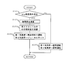
- FIG. 4 is a flowchart showing a NO X adsorption processing routine.
- the NO X adsorption processing routine is a routine stored in advance in the ROM or the like of the ECU 30 and is periodically executed by the ECU 30.
- the ECU 30 first determines whether or not the NO X adsorption condition of the rear catalyst 16 is satisfied in S101. For example, the ECU 30 determines whether or not the temperature of the rear catalyst 16 is lower than the activation temperature.
- the measured value of the exhaust temperature sensor 19 can be used as an alternative value.
- the measured value of the temperature sensor may be used as the temperature of the rear catalyst 16.
- the ECU 30 proceeds to S105 and operates the first cylinder group 2a and the second cylinder group 2b as usual. On the other hand, if a positive determination is made in S101, the ECU 30 proceeds to S102. In S102, the ECU 30 calculates the load factor of the internal combustion engine 1 (the load factor of the first cylinder group 2a when the second cylinder group 2b is fuel cut and the first cylinder group 2a is operated by gaseous fuel). To do.
- the ECU 30 calculates a target opening degree of the second throttle valve 13b. For example, the ECU 30 calculates the target intake air amount (upper limit value) of the second cylinder group 2b using the load factor calculated in S102 as a parameter. Next, the ECU 30 calculates the target opening of the second throttle valve 13b using the target intake air amount and the engine speed as parameters. Note that the ECU 30 may directly calculate the target opening of the second throttle valve 13b using the load factor and engine speed calculated in S102 as parameters.
- the ECU 30 controls the first supply device 100a and the second supply device 100b so that the first cylinder group 2a is operated by gaseous fuel and the second cylinder group 2b is fuel cut. Further, the ECU 30 controls the second throttle valve 13b so that the opening degree of the second throttle valve 13b matches the target opening degree calculated in S103.
- the control unit according to the present invention is realized. Therefore, when the rear stage catalyst 16 is in the deactivated state, without delaying the activity time of the rear stage catalyst 16 sharply, it is possible to reduce the amount of NO X discharged into the atmosphere as much as possible.
- the example in which the first cylinder group 2a is operated with gaseous fuel and the second cylinder group 2b is fuel cut has been described.
- the first cylinder group 2a is fuel cut and the second cylinder is cut.
- the group 2b may be operated with gaseous fuel.
- the first cylinder group 2a and the second cylinder group 2b may be alternately fuel cut.
- the cylinder group to be fuel-cut may be changed, and the first cylinder group 2a and the second cylinder group 2b are alternately arranged during one NO X adsorption process. It may be fuel cut.
- the detection value of the NO X sensor 31 (NO X outflow) of the second cylinder group 2b within a range showing a decreasing tendency A method of gradually increasing the intake air amount may be used.
- ECU 30 in the case of increasing the opening degree of the second throttle valve 13b by a constant amount, when the NO X runoff after increase is reduced more than the reference amount with respect to NO X runoff before increases, further increase a certain amount of opening of the second throttle valve 13b, the second throttle valve 13b at that time if not reduced NO X runoff after increasing the reference amount or more with respect to NO X runoff before increasing The opening degree may be maintained.
- the “reference amount” is a value determined based on the detection error of the NO X sensor 31 and the variation range of the NO X outflow amount when the amount of oxygen supplied to the rear catalyst 16 exceeds the predetermined amount Qo2. is there. According to such a method, the second throttle valve 13b can be controlled so that the NO X amount actually flowing out from the rear catalyst 16 (NO X outflow amount) is minimized.
Landscapes
- Engineering & Computer Science (AREA)
- Chemical & Material Sciences (AREA)
- Combustion & Propulsion (AREA)
- Mechanical Engineering (AREA)
- General Engineering & Computer Science (AREA)
- Oil, Petroleum & Natural Gas (AREA)
- Exhaust Gas After Treatment (AREA)
Abstract
本発明は、複数の気筒群と、各気筒群に接続される副排気通路と、それら複数の副排気通路を合流させて形成される主排気通路と、主排気通路に配置される三元触媒と、を備えた多種燃料内燃機関の制御システムにおいて、三元触媒のNOX吸着能を有効に活用することを課題とする。本発明は、上記の課題を解決するために、三元触媒が排気中のNOXを吸着可能な状態にあるときに、一部の気筒群を気体燃料により運転させるとともに、残りの気筒群をフューエルカットさせることにより、三元触媒へ供給される酸素量を増加させるようにした。
Description
本発明は、複数の気筒群を備えた多種燃料内燃機関の制御技術に関する。
近年、複数種の燃料により運転可能な多種燃料内燃機関が提案されている。多種燃料内燃機関において、該内燃機関の排気系に配置された吸蔵還元型NOX触媒のNOX還元処理を行うときに、液体燃料を使用する技術についても提案されている(たとえば、特許文献1を参照)。
ところで、内燃機関の排気系に三元触媒を配置し、内燃機関の冷間時などに排気中に含まれるNOXを三元触媒に吸着させることにより、排気エミッションの低減を図る場合がある。
本発明は、複数の気筒群と、各気筒群に接続される副排気通路と、それら複数の副排気通路を合流させて形成される主排気通路と、主排気通路に配置される三元触媒と、を備えた多種燃料内燃機関の制御システムにおいて、三元触媒のNOX吸着能を有効に活用することにより、排気エミッションの低減を図ることを目的とする。
本発明は、上記した課題を解決するために、複数の気筒群と、複数の気筒群から排出される排気が独立して流れる複数の副排気管と、複数の副排気管から排出される排気が合流して流れる主排気管と、主排気管に配置される三元触媒と、を備えた多種燃料内燃機関の制御システムにおいて、三元触媒が排気中の窒素酸化物を吸着可能な状態にあるときに、三元触媒へ供給される酸素量に応じて該三元触媒が吸着可能なNOX量が変化する事項に着目した。
内燃機関が気体燃料により運転されている場合は内燃機関が液体燃料により運転される場合に比べ、排気中の窒素酸化物(NOX)が三元触媒に吸着され易い。また、内燃機関が気体燃料により運転されているときに三元触媒へ流入する酸素量が多くなると、三元触媒へ流入する酸素量が少ない場合に比べ、三元触媒が吸着可能なNOX量(以下、「NOX吸着容量」と称する)が増大する。
これに対し、三元触媒の温度が活性温度より低いときに、内燃機関を気体燃料により運転させるとともに、内燃機関で燃焼される混合気の空燃比を理論空燃比より高く(リーン)する方法が考えられる。しかしながら、混合気の空燃比がリーンになると、内燃機関から排出されるNOX量が増加する可能性がある。
そこで、本発明は、複数の気筒群と、複数の気筒群から排出される排気が独立して流れる複数の副排気管と、複数の副排気管から排出される排気が合流して流れる主排気管と、主排気管に配置される三元触媒と、を備えた多種燃料内燃機関の制御システムであって、
各気筒群に液体燃料と気体燃料の何れか一方を供給する供給装置と、
前記三元触媒の温度が活性温度より低いときに、複数の気筒群のうち、一部の気筒群に気体燃料が供給されるとともに、残りの気筒群に対する燃料供給が停止されるように前記供給装置を制御する制御部と、
を備えるようにした。
各気筒群に液体燃料と気体燃料の何れか一方を供給する供給装置と、
前記三元触媒の温度が活性温度より低いときに、複数の気筒群のうち、一部の気筒群に気体燃料が供給されるとともに、残りの気筒群に対する燃料供給が停止されるように前記供給装置を制御する制御部と、
を備えるようにした。
このように構成された多種燃料内燃機関の制御システムによれば、一部の気筒群(以下、「第1気筒群」と称する)が気体燃料の既燃ガスを排出するとともに、残りの気筒群(以下、「第2気筒群」と称する)が空気のみを排出することになる。その場合、三元触媒へ流入するガスは、第1気筒群から排出される既燃ガスと第2気筒群から排出される空気との混合ガスとなる。つまり、三元触媒へ流入する排気は、空気(酸素)を多量に含有したガス(酸素過剰状態のガス)となる。その結果、三元触媒のNOX吸着容量が増加する。
したがって、三元触媒が未活性状態にあるときに、大気中へ排出されるNOXの量を減少させることができる。また、第1気筒群において燃焼される混合気の空燃比は理論空燃比以下に抑えることができるため、内燃機関から排出されるNOX量の増加を抑えることもできる。さらに、各気筒群の副排気管に前段触媒が設けられる場合においては、第1気筒群で燃焼される混合気の空燃比を前段触媒の早期活性や浄化性能に適した空燃比にすることもできる。
ここで、本願発明者が鋭意の実験及び検証を行った結果、三元触媒のNOX吸着容量は、該三元触媒へ供給される酸素量が所定量以下であるときは酸素供給量が多くなるほど増加するが、酸素供給量が所定量より多くなるときは略一定量になることがわかった。
そこで、本発明に係わる多種燃料内燃機関の制御システムは、三元触媒へ供給される酸素量が前記所定量と等しくなるように、第2気筒群の吸入空気量を調整してもよい。たとえば、本発明の多種燃料内燃機関の制御システムは、気筒群毎に吸入空気量を調整する調整部を更に備えるようにしてもよい。その場合、制御部は、第2気筒群の吸入空気量が上限値と等しくなるように調整部を制御してもよい。
ここでいう「上限値」は、三元触媒へ供給される酸素量が前記所定量と等しくなるときの第2気筒群の吸入空気量に相当する。前記上限値は、予め実験などを用いた適合処理によって求めておくようにしてもよい。なお、三元触媒へ供給される酸素量は、第2気筒群の吸入空気量に加え、第1気筒群の負荷率によっても変化する。よって、前記上限値は、第1気筒群の負荷率を引数として決定されるようにしてもよい。その際、上限値と第1気筒群の負荷率との関係は、予め実験的に求めておくようにしてもよい。
上記した方法により第2気筒群の吸入空気量が調整されると、三元触媒のNOX吸着容量を可及的に多くすることができる。その結果、大気中へ排出されるNOXの量が可及的に少なくなる。また、第2気筒群の吸入空気量が上限値に制限されると、三元触媒へ流入するガスの温度低下を最小限に抑えることもできる。その結果、三元触媒の温度上昇速度が大幅に低下する事態を回避することができる。すなわち、三元触媒の活性時期が大幅に遅くなる事態を回避することができる。
また、三元触媒へ供給される酸素量を所定量と等しくさせる他の方法としては、三元触媒から流出するNOXの量が減少傾向を示す範囲内において第2気筒群の吸入空気量を増加させる方法を用いることができる。たとえば、本発明の多種燃料内燃機関の制御システムは、気筒群毎に吸入空気量を調整する調整部と、三元触媒から流出するNOX量を取得するNOX量取得部と、を更に備えるようにしてもよい。その場合、制御部は、NOX量取得部により取得されるNOX量(以下、「NOX流出量」と称する)が減少傾向を示す範囲において、第2気筒群の吸入空気量を段階的に増加させるべく調整部を制御すればよい。
詳細には、制御部は、第2気筒群の吸入空気量を一定量ずつ増加させる場合において、吸入空気量の増加前におけるNOX流出量と吸入空気量の増加後におけるNOX流出量とを比較し、吸入空気量の増加前におけるNOX流出量に対して増加後におけるNOX流出量が基準量以上減少していれば第2気筒群の吸入空気量を更に一定量増加させる処理を実行し、吸入空気量の増加前におけるNOX流出量に対して増加後のNOX流出量が基準量以上減少していなければその時点における第2気筒群の吸入空気量を維持するようにしてもよい。なお、ここでいう「基準量」は、NOX量取得部により取得されるNOX量の誤差や、三元触媒へ供給される酸素量が前記所定量を超えたときのNOX流出量の変化幅など基づいて定められる値である。
上記した方法により第2気筒群の吸入空気量が調整されると、三元触媒へ供給される酸素量を前記所定量に収束させることができる。
なお、内燃機関が気筒群毎に独立した吸気管と各吸気管に配置されるスロットル弁とを備えている場合は、調整部は、第2気筒群の吸気管に設けられたスロットル弁の開度を制御することにより、第2気筒群の吸入空気量を調整してもよい。また、内燃機関が気筒群毎に独立した可変動弁機構を備えている場合は、調整部は第2気筒群に設けられた可変動弁機構を制御することにより、第2気筒群の吸入空気量を調整してもよい。
本発明によれば、複数の気筒群と、複数の気筒群から排出される排気が独立して流れる複数の副排気管と、複数の副排気管から排出される排気が合流して流れる主排気管と、主排気管に配置される三元触媒と、を備えた多種燃料内燃機関の制御システムにおいて、三元触媒のNOX吸着能を有効に活用することができるため、排気エミッションの低減を図ることができる。
以下、本発明の具体的な実施形態について図面に基づいて説明する。本実施形態に記載される構成部品の寸法、材質、形状、相対配置等は、特に記載がない限り発明の技術的範囲をそれらのみに限定する趣旨のものではない。
図1は、本発明を適用する内燃機関の概略構成を示す図である。図1に示す内燃機関1は、液体燃料と気体燃料を使用可能な火花点火式内燃機関である。なお、ここでいう「液体燃料」としては、ガソリン等の石油系液体燃料、またはエタノールやメタノール等が石油系液体燃料に混合された混合液体燃料などの非メタン炭化水素燃料を用いることができる。また、「気体燃料」としては、圧縮天然ガス(CNG)を用いることができる。
内燃機関1は、2つの気筒群2a,2bがV型に配列された内燃機関である。なお、図1に示す例では、各気筒群2a,2bにそれぞれ3つの気筒200a,200bが設けられているが、2つ以下であってもよく、或いは4つ以上であってもよい。また、2つの気筒群2a、2bは、互いに対向するように配置されてもよく、或いは直列に配置されてもよい。
2つの気筒群2a,2bのうち、一方の気筒群2a(以下、「第1気筒群2a」と称する)には、第1吸気管9aと第1副排気管10aとが接続されている。第1吸気管9aは、大気中から取り込まれた新気(空気)を第1気筒群2aの各気筒200aへ導くための通路である。第1副排気管10aは、第1気筒群2aの各気筒200aから排出されるガス(排気)を流すための通路である。
第1吸気管9aの途中には、第1スロットル弁13aが配置されている。第1スロットル弁13aは、第1吸気管9aの通路断面積を変更する弁体と該弁体を駆動するための電動アクチュエータを有し、第1気筒群2aの各気筒200aへ吸入される空気量を調整する。第1スロットル弁13aより上流の第1吸気管9aには、第1エアフローメータ14aが配置されている。第1エアフローメータ14aは、第1吸気管9a内を流れる空気量(質量)に相関した電気信号を出力するセンサである。
第1副排気管10aの途中には、第1前段触媒15aが配置されている。第1前段触媒15aは、低温状態にあるときに排気中の窒素酸化物(NOX)を吸着可能な三元触媒を含有している。第1前段触媒15aより上流の第1副排気管10aには、第1空燃比センサ17aが配置されている。第1空燃比センサ17aは、第1副排気管10a内を流れる排気の空燃比と相関する電気信号を出力するセンサである。
2つの気筒群2a,2bのうち、他方の気筒群2b(以下、「第2気筒群2b」と称する)には、第2吸気管9bと第2副排気管10bとが接続されている。第2吸気管9bは、大気中から取り込まれた空気を第2気筒群2bの各気筒200bへ導くための通路である。第2副排気管10bは、第2気筒群2bの各気筒200bから排出される排気を流すための通路である。
第2吸気管9bの途中には、第2スロットル弁13bが配置されている。第2スロットル弁13bは、第1スロットル弁13aと同様に構成され、第2気筒群2bの各気筒200bへ吸入される空気量を調整する。第2スロットル弁13bより上流の第2吸気管9bには、第2エアフローメータ14bが配置されている。第2エアフローメータ14bは、第2吸気管9b内を流れる空気量(質量)に対応した電気信号を出力するセンサである。
第2副排気管10bの途中には、第2前段触媒15bが配置されている。第2前段触媒15bは、第1前段触媒15aと同様に、低温状態にあるときに排気中のNOXを吸着可能な三元触媒を含有している。第2前段触媒15bより上流の第2副排気管10bには、第2空燃比センサ17bが配置されている。第2空燃比センサ17bは、第2副排気管10b内を流れる排気の空燃比と相関する電気信号を出力するセンサである。
第1副排気管10aと第2副排気管10bは、1本の主排気管10cに接続されている。主排気管10cは、第1副排気管10a及び第2副排気管10bから流出する排気を合流させて流す通路である。主排気管10cの途中には、後段触媒16が配置されている。後段触媒16は、前段触媒15a,15bと同様に、低温状態にあるときに排気中の窒素酸化物(NOX)を吸着可能な三元触媒を含有している。後段触媒16は、本発明に係わる三元触媒に相当する。
後段触媒16より下流の主排気管10cには、O2センサ18、排気温度センサ19、及びNOXセンサ31が配置されている。O2センサ18は、排気に含まれる酸素(O2)の濃度と相関する電気信号を出力するセンサである。排気温度センサ19は、排気の温度と相関する電気信号を出力するセンサである。NOXセンサ31は、後段触媒16から流出する排気に含まれるNOXの量(NOX流出量)と相関する電気信号を出力するセンサである。NOXセンサ31は、本発明に係わるNOX量取得部に相当する。
また、第1気筒群2aと第2気筒群2bには、供給装置100a,100bがそれぞれ設けられている。第1気筒群2aに設けられる供給装置100a(以下、「第1供給装置100a」と称する)は、第1気筒群2aの気筒200aに対して、液体燃料と気体燃料を選択的に供給する装置である。第2気筒群2bに設けられる供給装置100b(以下、「第2供給装置100b」と称する)は、第2気筒群2bの気筒200bに対して、液体燃料と気体燃料を選択的に供給する装置である。
ここで、供給装置100a,100bの構成について図2に基づいて説明する。図2は、第1気筒群2aの概略構成を示す図である。第1気筒群2aの各気筒200aには、ピストン3が摺動自在に装填されている。ピストン3は、図示しないコネクティングロッドを介して機関出力軸(クランクシャフト)に連結されている。
第1気筒群2aは、第1吸気管9aから気筒200a内へ新気(空気)を導くための吸気ポート4と、気筒200a内の既燃ガスを第1副排気管10aへ導くための排気ポート5と、を備えている。第1気筒群2aは、吸気ポート4の開口端を開閉するための吸気バルブ6と、排気ポート5の開口端を開閉するための排気バルブ7と、を備えている。吸気バルブ6と排気バルブ7は、図示しないインテークカムシャフトとエキゾーストカムシャフトによりそれぞれ開閉駆動される。また、第1気筒群2aは、気筒200a内に火種としての火花を発生させるための点火プラグ8を備えている。
第1供給装置100aは、第1燃料噴射弁11と、第1燃料通路110と、第1燃料タンク111と、燃料ポンプ112と、第1遮断弁113と、第2燃料噴射弁12と、第2燃料通路120と、第2燃料タンク121と、レギュレータ122と、第2遮断弁123と、を備えている。なお、第1燃料噴射弁11と第2燃料噴射弁12は、それぞれ気筒毎に設けられる。
第1燃料噴射弁11は、第1気筒群2aにおける吸気ポート4の近傍に取り付けられ、吸気ポート4内へ液体燃料を噴射する。第1燃料噴射弁11は、第1燃料通路110を介して第1燃料タンク111に連通している。第1燃料通路110の途中には、燃料ポンプ112と第1遮断弁113が配置されている。燃料ポンプ112は、第1燃料タンク111に貯留されている液体燃料を第1燃料噴射弁11へ供給する。第1遮断弁113は、第1燃料通路110の遮断と導通を切り替える機器である。
第2燃料噴射弁12は、第1吸気管9aにおける吸気ポート4の近傍に取り付けられ、第1吸気管9a内へ気体燃料を噴射する。第2燃料噴射弁12は、第2燃料通路120を介して第2燃料タンク(CNGボンベ)121に連通している。第2燃料通路120の途中には、レギュレータ122と第2遮断弁123が配置されている。レギュレータ122は、圧縮天然ガス(CNG)を所定の圧力まで減圧する機器である。第2遮断弁123は、第2燃料通路120の遮断と導通を切り替える機器である。また、第2燃料タンク121には、該第2燃料タンク121に貯蔵されている気体燃料の量に相関した電気信号を出力する残量センサ124が取り付けられている。
なお、第2気筒群2b及び第2供給装置100bの構成は、第1気筒群2a及び第1供給装置100aと同様であるため、ここでは説明を省略する。
このように構成された内燃機関1には、電子制御ユニット(ECU)30が併設されている。ECU30は、上記したエアフローメータ14a,14b、空燃比センサ17a,17b、O2センサ18、排気温度センサ19、およびNOXセンサ31に加え、アクセルポジションセンサ32などの各種センサと電気的に接続され、各種センサの出力信号を入力可能に構成されている。
また、ECU30は、上記した点火プラグ8、第1燃料噴射弁11、第2燃料噴射弁12、スロットル弁13a,13b、燃料ポンプ112、第1遮断弁113、第2遮断弁123などの各種機器と電気的に接続され、上記した各種センサの出力信号に応じて各種機器を制御可能に構成されている。
たとえば、ECU30は、内燃機関1が冷間始動された場合のように、後段触媒16が活性していない場合に、排気中のNOXを後段触媒16に吸着させるための処理(以下、「NOX吸着処理」と称する)を実行する。以下、本実施例におけるNOX吸着処理の実行方法について述べる。
後段触媒16に含有される三元触媒は、活性温度より低い低温状態にあるときに、排気中のNOXを吸着する。そのため、内燃機関1が冷間始動された場合のように、後段触媒16が未活性状態にある場合であっても、排気中のNOXが後段触媒16に吸着されれば、大気中に排出されるNOX量を少なく抑えることができる。
ただし、排気中に非メタン炭化水素が含まれている場合は、非メタン炭化水素がNOXに優先して後段触媒16に吸着される。そのため、後段触媒16が低温状態にあるときに排気中に含まれる非メタン炭化水素の量が多くなると、後段触媒16に吸着されるNOX量が少なくなる。その結果、大気中に排出されるNOX量が多くなる。
ここで、液体燃料(非メタン炭化水素燃料)の既燃ガスは、気体燃料(圧縮天然ガス(CNG))の既燃ガスに比べ、多量の非メタン炭化水素を含有する。よって、後段触媒16が未活性状態にあるときに内燃機関1が液体燃料により運転されると、後段触媒16が吸着可能なNOX量(NOX吸着容量)が減少する。その結果、大気中へ排出されるNOX量を十分に低減することができない可能性がある。
これに対し、後段触媒16が未活性状態にあるときに内燃機関1が気体燃料により運転されると、後段触媒16のNOX吸着容量を増加させることができる。そのため、大気中へ排出されるNOX量を少なく抑えることが可能となる。さらに、後段触媒16のNOX吸着容量は、図3に示すように、該後段触媒16へ流入する酸素量が少ないときより多いときの方が増加する。ここで、後段触媒16が未活性状態にあるときに、内燃機関1が気体燃料により運転されるとともに、各気筒200a,200bで燃焼される混合気の空燃比がリーンにされると、後段触媒16へ流入する酸素量を増加させることができる。ただし、混合気の空燃比がリーンにされた場合は理論空燃比にされた場合に比べ、既燃ガス(排気)中に含まれるNOXの量が多くなる。
そこで、本実施例におけるNOX吸着処理では、ECU30は、後段触媒16の温度が活性温度より低いときに、2つの気筒群2a,2bの一方を気体燃料により運転させるとともに、2つの気筒群2a,2bの他方に対する燃料供給を停止(フューエルカット)させるようにした。ここでは、第1気筒群2aが気体燃料により運転されるとともに、第2気筒群2bがフューエルカットされる例について述べる。
第1気筒群2aが気体燃料により運転されるとともに、第2気筒群2bがフューエルカットされた場合は、第1気筒群2aから既燃ガスが排出されるとともに、第2気筒群2bから空気が排出されることになる。第1気筒群2aから排出される既燃ガスは、第1副排気管10aを介して主排気管10cへ導かれる。第2気筒群2bから排出される空気は、第2副排気管10bを介して主排気管10cへ導かれる。その結果、第1気筒群2aから排出された既燃ガスと第2気筒群2bから排出された空気との混合ガスが後段触媒16へ流入することになる。前記混合ガスは多量の酸素を含有したガスであるため、後段触媒16のNOX吸着容量が増大する。
ところで、第2気筒群2bから排出される空気量が不用意に決定されると、後段触媒16の活性時期が遅くなったり、後段触媒16のNOX吸着容量が十分に増加されなかったりする可能性がある。後段触媒16のNOX吸着容量は、前述した図3に示すように、該後段触媒16へ供給される酸素量が所定量(図3中のQo2)以下であるときは、酸素供給量が多くなるほど増加する。一方、酸素供給量が所定量Qo2より多いときは、酸素供給量にかかわらずNOX吸着容量が略一定となる。したがって、酸素供給量が所定量Qo2より少なくなると、後段触媒16のNOX吸着能を十分に活用することができなくなる。一方、酸素供給量が所定量Qo2より多くなると、排気温度が大幅な低下により後段触媒16の活性時期が大幅に遅れる可能性がある。
これに対し、ECU30は、後段触媒16へ供給される酸素量が前記所定量Qo2と等しくなるように、第2気筒群2bから排出される空気量を調整するようにした。第2気筒群2bから排出される空気量は、該第2気筒群2bに吸入空気量される空気量と同等である。よって、ECU30は、第2エアフローメータ14bの検出値が所定の上限値と等しくなるように、第2気筒群2bの吸入空気量を調整するようにした。ここでいう「上限値」は、後段触媒16へ供給される酸素量が前記所定量Qo2と等しくなるときの第2気筒群2bの吸入空気量に相当する値である。
なお、後段触媒16に供給される酸素量は、第2気筒群2bの排気に含まれる酸素量に加え、第1気筒群2aの排気に含まれる酸素量によっても変化する。第1気筒群2aの排気に含まれる酸素量は、第1気筒群2aの負荷率と相関するため、前記上限値は第1気筒群2aの負荷率をパラメータとして決定されてもよい。その際、第1気筒群2aの負荷率と上限値との関係を予め実験的に求めておき、それらの関係をマップ化しておくようにしてもよい。
第2気筒群2bの吸入空気量を調整する方法としては、第2スロットル弁13bの開度を調整する方法を用いることができる。その場合は、第2スロットル弁13bが本発明に係わる調整部に相当する。また、吸気バルブ6の開弁特性(開閉タイミングや作用角)を変更可能な可変動弁機構が第2気筒群2bに設けられている場合は、該可変動弁機構を制御することにより第2気筒群2bの吸入空気量を調整してもよい。その場合は、可変動弁機構が本発明に係わる調整部に相当する。
なお、第2気筒群2bの吸入空気量を調整する手段として第2スロットル弁13bが用いられる場合は、第1気筒群2aの負荷率と上限値との相関関係の代わりに、第1気筒群2aの負荷率と第2スロットル弁13bの開度との相関関係をマップ化しておくようにしてもよい。また、第2気筒群2bの吸入空気量を調整する手段として可変動弁機構が用いられる場合は、第1気筒群2aの負荷率と上限値との相関関係の代わりに、第1気筒群2aの負荷率と吸気バルブ6の開弁特性との相関関係をマップ化しておくようにしてもよい。
このような方法により第2気筒群2bの吸入空気量が調整されると、後段触媒16に供給される酸素量を前記所定量Qo2と同等にすることができる。その結果、後段触媒16のNOX吸着容量を可及的に多くすることができる。よって、後段触媒16が未活性状態にあるときに大気中へ排出されるNOX量を可及的に少なくすることができる。さらに、第2気筒群2bの吸入空気量が前記上限値に制限されると、後段触媒16へ流入する排気の温度低下量を最小限に抑えることができる。その結果、後段触媒16の活性時期が大幅に遅くなる事態を回避することができる。よって、後段触媒16の活性時期の遅延に起因した排気エミッションの増加を抑えることも可能となる。また、第1気筒群2aで燃焼される混合気の空燃比は、第1前段触媒15aの早期活性若しくは第1前段触媒15aの浄化特性に適した空燃比(たとえば、理論空燃比)にすることもできる。その結果、第1前段触媒15aの浄化能力を活用しつつ後段触媒16のNOX吸着容量を拡大することも可能になる。
以下、本実施例におけるNOX吸着処理の実行手順について図4に沿って説明する。図4は、NOX吸着処理ルーチンを示すフローチャートである。NOX吸着処理ルーチンは、予めECU30のROMなどに記憶されているルーチンであり、ECU30によって周期的に実行される。
図4のNOX吸着処理ルーチンでは、ECU30は、先ずS101において後段触媒16のNOX吸着条件が成立しているか否かを判別する。たとえば、ECU30は、後段触媒16の温度が活性温度未満であるか否かを判別する。ここで、後段触媒16の温度としては、排気温度センサ19の測定値を代替値として用いることができる。なお、後段触媒16に温度センサが取り付けられている場合は、該温度センサの測定値を後段触媒16の温度として用いてもよい。
前記S101において否定判定された場合は、ECU30は、S105へ進み、第1気筒群2a及び第2気筒群2bを通常通りに運転させる。一方、前記S101において肯定判定された場合は、ECU30は、S102へ進む。S102では、ECU30は、内燃機関1の負荷率(第2気筒群2bがフューエルカットされ、且つ、第1気筒群2aが気体燃料により運転されるときの第1気筒群2aの負荷率)を演算する。
S103では、ECU30は、第2スロットル弁13bの目標開度を演算する。たとえば、ECU30は、前記S102で算出された負荷率をパラメータとして第2気筒群2bの目標吸入空気量(上限値)を演算する。次いで、ECU30は、目標吸入空気量と機関回転数とをパラメータとして、第2スロットル弁13bの目標開度を演算する。なお、ECU30は、前記S102で演算された負荷率と機関回転数とをパラメータとして、第2スロットル弁13bの目標開度を直接演算してもよい。
S104では、ECU30は、第1気筒群2aが気体燃料により運転されるとともに、第2気筒群2bがフューエルカットされるように、第1供給装置100a及び第2供給装置100bを制御する。さらに、ECU30は、第2スロットル弁13bの開度が前記S103で算出された目標開度と一致するように、第2スロットル弁13bを制御する。
前記したS102乃至S104の処理は、NOX吸着条件が成立している限りにおいて繰り返し実行される。その結果、後段触媒16が未活性状態にあるときに該後段触媒16へ供給される酸素量は、前記所定量Qo2と等しくなる。
このようにECU30が図4のNOX吸着処理ルーチンを実行することにより、本発明に係わる制御部が実現される。よって、後段触媒16が未活性状態にあるときに、該後段触媒16の活性時期を大幅に遅らせることなく、大気中へ排出されるNOX量を可及的に少なくすることが可能となる。
本実施例のNOX吸着処理では、第1気筒群2aを気体燃料により運転させるとともに第2気筒群2bをフューエルカットする例について述べたが、第1気筒群2aをフューエルカットさせるとともに第2気筒群2bを気体燃料により運転させてもよい。また、第1気筒群2aと第2気筒群2bが交互にフューエルカットされるようにしてもよい。その際、NOX吸着処理が実行される都度、フューエルカットされる気筒群を変更してもよく、1回のNOX吸着処理実行中に第1気筒群2aと第2気筒群2bが交互にフューエルカットされてもよい。
また、後段触媒16へ供給される酸素量を所定量Qo2と等しくさせる他の方法として、NOXセンサ31の検出値(NOX流出量)が減少傾向を示す範囲内において第2気筒群2bの吸入空気量を段階的に増加させる方法を用いてもよい。たとえば、ECU30は、第2スロットル弁13bの開度を一定量ずつ増加させる場合において、増加前におけるNOX流出量に対して増加後におけるNOX流出量が基準量以上減少しているときは、第2スロットル弁13bの開度をさらに一定量増加させ、増加前におけるNOX流出量に対して増加後のNOX流出量が基準量以上減少していなければその時点における第2スロットル弁13bの開度を維持するようにしてもよい。ここでいう「基準量」は、NOXセンサ31の検出誤差や、後段触媒16へ供給される酸素量が所定量Qo2を超えたときのNOX流出量の変化幅など基づいて定められる値である。このような方法によれば、後段触媒16から実際に流出するNOX量(NOX流出量)が最少となるように第2スロットル弁13bを制御することができる。
1 内燃機関
2a 第1気筒群
2b 第2気筒群
3 ピストン
4 吸気ポート
5 排気ポート
6 吸気バルブ
7 排気バルブ
8 点火プラグ
9a 第1吸気管
9b 第2吸気管
10a第1副排気管
10b第2副排気管
10c主排気管
11 第1燃料噴射弁
12 第2燃料噴射弁
13a第1スロットル弁
13b第2スロットル弁
14a第1エアフローメータ
14b第2エアフローメータ
15a第1前段触媒
15b第2前段触媒
16 後段触媒
17a第1空燃比センサ
17b第2空燃比センサ
18 O2センサ
19 排気温度センサ
30 ECU
31 NOXセンサ
100a 第1供給装置
100b 第2供給装置
200a 気筒
200b 気筒
2a 第1気筒群
2b 第2気筒群
3 ピストン
4 吸気ポート
5 排気ポート
6 吸気バルブ
7 排気バルブ
8 点火プラグ
9a 第1吸気管
9b 第2吸気管
10a第1副排気管
10b第2副排気管
10c主排気管
11 第1燃料噴射弁
12 第2燃料噴射弁
13a第1スロットル弁
13b第2スロットル弁
14a第1エアフローメータ
14b第2エアフローメータ
15a第1前段触媒
15b第2前段触媒
16 後段触媒
17a第1空燃比センサ
17b第2空燃比センサ
18 O2センサ
19 排気温度センサ
30 ECU
31 NOXセンサ
100a 第1供給装置
100b 第2供給装置
200a 気筒
200b 気筒
Claims (3)
- 複数の気筒群と、
複数の気筒群から排出される排気が独立して流れる複数の副排気管と、
複数の副排気管から排出される排気が合流して流れる主排気管と、
主排気管に配置される三元触媒と、
を備えた多種燃料内燃機関の制御システムであって、
各気筒群へ液体燃料と気体燃料の何れか一方を供給する供給装置と、
前記三元触媒の温度が活性温度より低いときに、複数の気筒群のうち、一部の気筒群に気体燃料が供給されるとともに、残りの気筒群に対する燃料供給が停止されるように前記供給装置を制御する制御部と、
を備える多種燃料内燃機関の制御システム。 - 請求項1において、気筒群毎に吸入空気量を調整する調整部を更に備え、
前記制御部は、前記した残りの気筒群の吸入空気量が上限値と等しくなるように前記調整部を制御する多種燃料内燃機関の制御システム。 - 請求項1において、気筒群毎に吸入空気量を調整する調整部と、
前記三元触媒から流出するNOX量を取得するNOX量取得部と、
を更に備え、
前記制御部は、前記NOX量取得部により取得されるNOX量が減少傾向を示す範囲において、前記した残りの気筒群の吸入空気量を段階的に増加させるべく前記調整部を制御する多種燃料内燃機関の制御システム。
Priority Applications (1)
| Application Number | Priority Date | Filing Date | Title |
|---|---|---|---|
| PCT/JP2011/060987 WO2012153423A1 (ja) | 2011-05-12 | 2011-05-12 | 多種燃料内燃機関の制御システム |
Applications Claiming Priority (1)
| Application Number | Priority Date | Filing Date | Title |
|---|---|---|---|
| PCT/JP2011/060987 WO2012153423A1 (ja) | 2011-05-12 | 2011-05-12 | 多種燃料内燃機関の制御システム |
Publications (1)
| Publication Number | Publication Date |
|---|---|
| WO2012153423A1 true WO2012153423A1 (ja) | 2012-11-15 |
Family
ID=47138921
Family Applications (1)
| Application Number | Title | Priority Date | Filing Date |
|---|---|---|---|
| PCT/JP2011/060987 Ceased WO2012153423A1 (ja) | 2011-05-12 | 2011-05-12 | 多種燃料内燃機関の制御システム |
Country Status (1)
| Country | Link |
|---|---|
| WO (1) | WO2012153423A1 (ja) |
Citations (2)
| Publication number | Priority date | Publication date | Assignee | Title |
|---|---|---|---|---|
| JP2003206772A (ja) * | 2002-01-11 | 2003-07-25 | Toyota Motor Corp | バイフューエル車用内燃機関の燃料制御装置 |
| JP2007127064A (ja) * | 2005-11-04 | 2007-05-24 | Toyota Motor Corp | 内燃機関の排気浄化装置 |
-
2011
- 2011-05-12 WO PCT/JP2011/060987 patent/WO2012153423A1/ja not_active Ceased
Patent Citations (2)
| Publication number | Priority date | Publication date | Assignee | Title |
|---|---|---|---|---|
| JP2003206772A (ja) * | 2002-01-11 | 2003-07-25 | Toyota Motor Corp | バイフューエル車用内燃機関の燃料制御装置 |
| JP2007127064A (ja) * | 2005-11-04 | 2007-05-24 | Toyota Motor Corp | 内燃機関の排気浄化装置 |
Similar Documents
| Publication | Publication Date | Title |
|---|---|---|
| JP5682707B2 (ja) | 多種燃料内燃機関の制御システム | |
| JP2009216056A (ja) | 内燃機関の排気再循環装置 | |
| US20080148718A1 (en) | Engine system and method for purge gas regeneration of an exhaust gas treatment device in such a system | |
| JP5862552B2 (ja) | 内燃機関の燃料噴射制御装置 | |
| JP2010203326A (ja) | 内燃機関の制御装置 | |
| US8448425B2 (en) | Engine system and a method for a regeneration of an exhaust gas treatment device in such a system | |
| US20130151118A1 (en) | Air-fuel ratio control apparatus, and control method, of hybrid power unit | |
| US6732503B2 (en) | Air/fuel ratio controller for internal combustion engine | |
| JP6235455B2 (ja) | 内燃機関の燃料噴射装置 | |
| JP5067510B2 (ja) | 内燃機関の燃料噴射システム | |
| EP1936163B1 (en) | An engine system and an exhaust gas treatment device regeneration method | |
| WO2011145603A1 (ja) | 内燃機関の燃料供給装置及び燃料供給制御方法 | |
| JP2008157243A (ja) | エンジンシステムおよび同システムにおける排ガス処理装置の再生方法 | |
| WO2012153423A1 (ja) | 多種燃料内燃機関の制御システム | |
| CN110857645B (zh) | 内燃机的排气净化装置和排气净化方法 | |
| WO2012153424A1 (ja) | 多種燃料内燃機関の制御システム | |
| JP2016125478A (ja) | 内燃機関の空燃比制御装置 | |
| JP2009287533A (ja) | 内燃機関の蒸発燃料処理装置 | |
| JP2005083205A (ja) | 内燃機関の制御装置 | |
| WO2012147184A1 (ja) | 内燃機関の制御システム | |
| WO2012147183A1 (ja) | 内燃機関の制御システム | |
| WO2014208009A1 (ja) | 内燃機関の噴射制御装置 | |
| JP5310413B2 (ja) | 内燃機関の燃料噴射制御装置 | |
| WO2014115510A1 (ja) | 内燃機関の燃料噴射装置 | |
| JP2012255423A (ja) | 内燃機関の制御装置 |
Legal Events
| Date | Code | Title | Description |
|---|---|---|---|
| 121 | Ep: the epo has been informed by wipo that ep was designated in this application |
Ref document number: 11865352 Country of ref document: EP Kind code of ref document: A1 |
|
| NENP | Non-entry into the national phase |
Ref country code: DE |
|
| 122 | Ep: pct application non-entry in european phase |
Ref document number: 11865352 Country of ref document: EP Kind code of ref document: A1 |
|
| NENP | Non-entry into the national phase |
Ref country code: JP |