WO2012147997A1 - 電子機器 - Google Patents
電子機器 Download PDFInfo
- Publication number
- WO2012147997A1 WO2012147997A1 PCT/JP2012/061698 JP2012061698W WO2012147997A1 WO 2012147997 A1 WO2012147997 A1 WO 2012147997A1 JP 2012061698 W JP2012061698 W JP 2012061698W WO 2012147997 A1 WO2012147997 A1 WO 2012147997A1
- Authority
- WO
- WIPO (PCT)
- Prior art keywords
- contact
- unit
- area
- tactile sensation
- detection unit
- Prior art date
- Legal status (The legal status is an assumption and is not a legal conclusion. Google has not performed a legal analysis and makes no representation as to the accuracy of the status listed.)
- Ceased
Links
Images





Classifications
-
- G—PHYSICS
- G03—PHOTOGRAPHY; CINEMATOGRAPHY; ANALOGOUS TECHNIQUES USING WAVES OTHER THAN OPTICAL WAVES; ELECTROGRAPHY; HOLOGRAPHY
- G03B—APPARATUS OR ARRANGEMENTS FOR TAKING PHOTOGRAPHS OR FOR PROJECTING OR VIEWING THEM; APPARATUS OR ARRANGEMENTS EMPLOYING ANALOGOUS TECHNIQUES USING WAVES OTHER THAN OPTICAL WAVES; ACCESSORIES THEREFOR
- G03B13/00—Viewfinders; Focusing aids for cameras; Means for focusing for cameras; Autofocus systems for cameras
- G03B13/18—Focusing aids
-
- G—PHYSICS
- G03—PHOTOGRAPHY; CINEMATOGRAPHY; ANALOGOUS TECHNIQUES USING WAVES OTHER THAN OPTICAL WAVES; ELECTROGRAPHY; HOLOGRAPHY
- G03B—APPARATUS OR ARRANGEMENTS FOR TAKING PHOTOGRAPHS OR FOR PROJECTING OR VIEWING THEM; APPARATUS OR ARRANGEMENTS EMPLOYING ANALOGOUS TECHNIQUES USING WAVES OTHER THAN OPTICAL WAVES; ACCESSORIES THEREFOR
- G03B17/00—Details of cameras or camera bodies; Accessories therefor
- G03B17/18—Signals indicating condition of a camera member or suitability of light
-
- H—ELECTRICITY
- H04—ELECTRIC COMMUNICATION TECHNIQUE
- H04N—PICTORIAL COMMUNICATION, e.g. TELEVISION
- H04N23/00—Cameras or camera modules comprising electronic image sensors; Control thereof
- H04N23/60—Control of cameras or camera modules
- H04N23/62—Control of parameters via user interfaces
-
- H—ELECTRICITY
- H04—ELECTRIC COMMUNICATION TECHNIQUE
- H04N—PICTORIAL COMMUNICATION, e.g. TELEVISION
- H04N23/00—Cameras or camera modules comprising electronic image sensors; Control thereof
- H04N23/60—Control of cameras or camera modules
- H04N23/67—Focus control based on electronic image sensor signals
- H04N23/675—Focus control based on electronic image sensor signals comprising setting of focusing regions
-
- H—ELECTRICITY
- H04—ELECTRIC COMMUNICATION TECHNIQUE
- H04N—PICTORIAL COMMUNICATION, e.g. TELEVISION
- H04N23/00—Cameras or camera modules comprising electronic image sensors; Control thereof
- H04N23/60—Control of cameras or camera modules
- H04N23/63—Control of cameras or camera modules by using electronic viewfinders
- H04N23/631—Graphical user interfaces [GUI] specially adapted for controlling image capture or setting capture parameters
-
- H—ELECTRICITY
- H04—ELECTRIC COMMUNICATION TECHNIQUE
- H04N—PICTORIAL COMMUNICATION, e.g. TELEVISION
- H04N23/00—Cameras or camera modules comprising electronic image sensors; Control thereof
- H04N23/60—Control of cameras or camera modules
- H04N23/67—Focus control based on electronic image sensor signals
Definitions
- the present invention relates to an electronic device including a contact detection unit.
- buttons such as a shutter button, a zoom-up button, and a zoom-down button are displayed so as to be superimposed on a photographed image, and by touching these buttons, an auto-focus operation, a zoom operation, and a shutter are performed. It can be operated.
- processing such as auto-focusing is performed by touching the touch panel.
- the adjustment of the focal length is based on the perspective of the focal length displayed on the touch panel. Since this is performed by touching a button or the like for adjusting the display, the display screen is occupied by the button.
- operations such as touching a button displayed on the display screen may be used to increase or decrease parameters associated with a predetermined process, such as enlargement or reduction of the display screen. It was necessary.
- the present invention has been made in view of such problems, and an object of the present invention is to provide an electronic device that does not require a button or the like for increasing or decreasing parameters associated with a predetermined process. There is.
- an electronic device of the present invention is an electronic device that increases or decreases a parameter associated with a predetermined process according to a contact area, a contact detection unit that detects contact of a contact object, A control unit configured to increase or decrease the parameter based on a contact area between the contact detection unit and the contact object and a reference area;
- the electronic apparatus further includes an imaging unit that images a subject, and the control unit increases or decreases the parameter based on the contact area and the reference area, thereby reducing a focal length.
- the imaging unit is controlled as described above.
- the electronic device of the present invention further includes a tactile sensation providing unit that provides a tactile sensation to the contact object that is in contact with the contact detection unit, and the control unit has a contact area between the contact detection unit and the contact object.
- the tactile sensation providing unit is controlled so as to present a tactile sensation to the contact object when the contact area is equal to or larger than the reference area, and the tactile sensation providing unit is controlled to present the tactile sensation to the contact object, and then the contact detection unit
- the focal distance is reduced, and when the contact area between the contact detection unit and the contact object is equal to or greater than the reference area, the focal distance is determined.
- the imaging unit is controlled so as to be away from the camera.
- the contact area between the contact detection unit and the contact object is obtained, and the parameter is increased or decreased based on the obtained contact area and the reference area, so a button or the like for increasing or decreasing the parameter is provided on the display screen.
- the present invention obtains the contact area between the contact detection unit and the contact object, and increases or decreases the parameter based on the obtained contact area and the reference area, so that the operator can intuitively and smoothly set the parameter. It can be increased or decreased.
- FIG. 1 is a block diagram showing a schematic configuration of an electronic apparatus according to an embodiment of the present invention.
- the electronic device 1 includes a contact detection unit 10, a display unit 20, an imaging unit 30, a storage unit 40, a tactile sensation providing unit 50, and a control unit 60.
- the imaging unit 30 includes a photographic lens and shoots a subject.
- the imaging unit 30 also has a focus function that focuses the lens on the subject and a function that adjusts the aperture of the lens.
- the display unit 20 displays the video imaged by the imaging unit 30.
- the display unit 20 is configured using, for example, a liquid crystal display panel (LCD), an organic EL display panel, or the like.
- the contact detection unit 10 is normally arranged on the front surface of the display unit 20 and makes contact with a contact object (pressed object) such as an operator's finger on the image displayed on the display screen of the display unit 20 or release of the contact. Then, detection is performed on the input surface 10a of the contact detection unit 10 corresponding to the displayed image. The contact detection unit 10 detects contact with the input surface 10 a and notifies the control unit 60 of the contact. Further, the contact detection unit 10 is configured by a known type such as a resistance film type or a capacitance type, and in the case of the resistance film type, a signal based on a resistance change caused by contact of a contact object is transmitted to the control unit 60.
- a contact object pressed object
- the contact detection unit 10 is configured by a known type such as a resistance film type or a capacitance type, and in the case of the resistance film type, a signal based on a resistance change caused by contact of a contact object is transmitted to the control unit 60.
- a signal based on a change in electrostatic capacity due to contact of a contact object is output to the control unit 60.
- the touch panel 20 detects the contact by a contact thing, it is not essential that a contact thing touches the touch panel 20 physically.
- the touch panel 20 is optical, the touch panel 20 detects a position where the infrared light on the touch panel 20 is blocked by the contact object, and thus it is not necessary for the contact object to touch the touch panel 20.
- the control unit 60 starts a predetermined process based on the contact of the contact object in the contact detection unit 10. Further, the control unit 60 obtains a contact area based on a signal output from the contact detection unit 10 based on a resistance change due to contact of a contact object or a signal based on a change in capacitance, and the obtained contact area and a reference
- the imaging unit 30 is controlled by increasing / decreasing the parameter based on the area and increasing / decreasing the parameter.
- the predetermined process in the present embodiment is a photographing process (operation) described later, and the parameter associated with the predetermined process is a parameter for reducing the focal length in the photographing process.
- the description “to increase the focal length by increasing a parameter for increasing the focal length” is referred to as “to decrease the focal length” and “to reduce the focal length”.
- the description “reducing the focal length by reducing the parameter of” is omitted from the description “reducing the focal length”. Note that the increase or decrease in the parameter for reducing the focal length may be associated with either the perspective of the focal length. In other words, when the control unit 60 increases the parameter for reducing the focal length, the focal length may be increased or decreased.
- control unit 60 instructs the tactile sensation providing unit 50 to perform a tactile sensation providing operation when the contact area between the contact detection unit 10 and the contact object is equal to or larger than the reference area.
- control unit 60 reduces the focal distance so that the contact area between the contact detection unit 10 and the contact object is less than the reference area. If the area is equal to or larger than the reference area, the imaging unit 30 is controlled so as to increase the focal length.
- the tactile sensation providing unit 50 is configured using, for example, a piezoelectric vibrator or the like, and presents a predetermined tactile sensation to a contact object that is in contact with the input surface 10a by generating vibration according to a predetermined vibration pattern. .
- the tactile sensation providing unit 50 can generate vibrations of the “contact feeling” pattern, the “shallow pressing feeling” pattern, and the “deep pressing feeling” pattern.
- the “contact feeling” pattern is, for example, a vibration pattern with a constant amplitude
- the “shallow pressing feeling” pattern is, for example, a vibration pattern with gradually decreasing amplitude
- the “deep pressing feeling” pattern is, for example, This is a vibration pattern in which the amplitude gradually increases.
- the storage unit 40 can be composed of a memory according to a known technique, and stores various input information, a program for operating the electronic device 1, and the like, and also functions as a work memory.
- the storage unit 40 stores a reference area value used by the control unit 60 to determine the size of the contact area between the contact detection unit 10 and the contact object, and the tactile sensation providing unit 50
- the vibration data of the “contact feeling” pattern, the “shallow pressing feeling” pattern, and the “deep pressing feeling” pattern when the vibration is generated is stored.
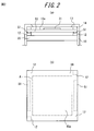
- FIG. 2 shows an example of a mounting structure of the electronic device 1 shown in FIG. 1, FIG. 2 (a) is a cross-sectional view of the main part, and FIG. 2 (b) is a plan view of the main part.
- the display unit 20 is housed and held in the housing 11.
- a contact detection unit 10 is held on the display unit 20 via an insulator 12 made of an elastic member.
- display unit 20 and contact detection unit 10 have a rectangular shape in plan view.
- the contact detection unit 10 is held on the display unit 20 via the insulators 12 disposed at the four corners deviated from the display area A of the display unit 20 indicated by phantom lines in FIG. ing.
- the housing 11 is provided with an upper cover 13 so as to cover the surface area of the contact detection unit 10 that is out of the display area of the display unit 20.
- An insulator 14 made of an elastic member is disposed between the upper cover 13 and the contact detection unit 10.
- the contact detection part 10 shown in FIG. 2 comprises the surface member which has the input surface 10a, for example with a transparent film or glass, and comprises the back member with glass or acrylic.
- a piezoelectric vibrator 51 for vibrating the contact detection unit 10 is provided in the vicinity of two opposing sides by bonding or the like. That is, the electronic device 1 shown in FIG. 2 includes the tactile sensation providing unit 50 shown in FIG. 1 using two piezoelectric vibrators 51. The tactile sensation providing unit 50 vibrates the input surface 10a by vibrating the contact detection unit 10.
- FIG. 2B the casing 11, the upper cover 13, and the insulator 14 shown in FIG. 2A are not shown.
- FIG. 3 is a flowchart showing the operation of the electronic apparatus 1 according to the present embodiment.
- the control unit 60 displays the photographed image on the display unit 20 (step S101), and the contact area between the contact detection unit 10 and a contact object such as an operator's finger is It is determined whether or not the area is equal to or larger than the reference area (step S102).
- step S102 when the contact area between the contact detection unit 10 and the contacted object is equal to or larger than the reference area, the control unit 60 performs a tactile sensation operation of the “contact feeling” pattern on the tactile sensation providing unit 50.
- An instruction is given (step S103).
- the control unit 60 can notify the operator that the operation start has been received by causing the tactile sensation providing unit 50 to perform the tactile sensation presentation operation of the “contact feeling” pattern.
- the “contact feeling” pattern is, for example, a vibration pattern having a constant amplitude.
- the control unit 60 determines whether or not the contact area between the contact detection unit 10 and the contact object is less than the reference area (step S104).
- the control unit 60 causes the tactile sensation providing unit 50 to perform a tactile sensation operation of the “shallow press feeling” pattern (step S105).
- the “shallow press feeling” pattern is, for example, a vibration pattern in which the amplitude gradually decreases.
- the control unit 60 determines whether or not the aperture value (F value) of the lens of the imaging unit 30 is greater than or equal to a predetermined value (step S106).
- the control unit 60 When the aperture of the lens is closed and the aperture value (F value) is large as in the case where the shooting mode is landscape mode, the control unit 60 is when the aperture value is greater than or equal to a predetermined value (Yes in step S106). ) Sets the aperture value of the lens to an open value (step S107), and then instructs the imaging unit 30 to focus on the foreground (close the focal length) (step S108). If the aperture value is less than the predetermined value (No in step S106), the control unit 60 does not change the lens aperture value so that the imaging unit 30 is focused on the foreground (focal length). (Step S108). Thereafter, the control unit 60 monitors contact with the contact detection unit 10 by a finger other than the finger currently in contact with the operator (step S109), and does not detect contact with another finger of the operator. If (No in step S109), the process returns to step S104.
- step S104 when the contact area is equal to or larger than the reference area (No in step S104), the control unit 60 causes the tactile sensation providing unit 50 to perform the tactile sensation operation of the “deep pressing feeling” pattern (step S104).
- the “deep pressing feeling” pattern is, for example, a vibration pattern in which the amplitude gradually increases.
- the control unit 60 determines whether or not the aperture value (F value) of the lens of the imaging unit 30 is greater than or equal to a predetermined value (step S111).
- the control unit 60 When the aperture of the lens is closed and the aperture value (F value) is large, that is, when the aperture value is greater than or equal to a predetermined value, such as when the shooting mode is landscape mode, the control unit 60 (Yes in step S111) ) Sets the aperture value of the lens to an open value (step S112), and then instructs the imaging unit 30 to focus on a distant view (to reduce the focal length) (step S113). When the aperture value is less than the predetermined value (No in step S111), the control unit 60 focuses the image capturing unit 30 on a distant view without changing the lens aperture value (focal length). (Step S113).
- control unit 60 monitors contact with the contact detection unit 10 by a finger other than the finger currently in contact with the operator (step S114) and does not detect contact with the other finger of the operator. (If No in step S114), the process returns to step S104.
- step S109 and step S114 the control unit 60 causes the tactile sensation providing unit 50 to perform a tactile sensation display operation of the “contact sensation” pattern when detecting contact with another finger or the like of the operator (step S115). Then, the imaging unit 30 is instructed to fix the focal length and aperture value, release the shutter, and capture the image (step S116).
- FIG. 4 shows an example of a photographed image in the case where there is strong light in the photographing frame, such as sunset scenery photography or morning sun scenery photography. If there is strong light in the shooting frame, shooting in the normal landscape mode will focus on everything from the near view to the distant view as shown in FIG. For example, the photographer (operator) automatically opens the aperture by adjusting the increase / decrease of the contact area of the finger with the finger touching the screen with the landscape mode set. To the desired position while viewing the shooting screen.
- FIG. 4B shows an image when the electronic device according to the present embodiment is set with the aperture set to an open value (with a small F value) and is photographed while focusing on a distant view.
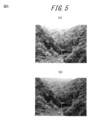
- FIG. 5 shows an example of a photographed image of a monotonous landscape having a depth such as a mountain slope when photographing autumn leaves.
- a monotonous landscape having a depth such as a mountain foliage landscape is photographed in the normal landscape mode, as shown in FIG. 5A, all of the close-up view to the distant view are in focus.
- the photographer automatically opens the aperture by adjusting the increase or decrease of the contact area of the finger with the finger touching the screen in the landscape mode setting (the aperture value is set to the open value).
- FIG. 5B shows an image when the electronic apparatus according to the present embodiment is set with the aperture set to the open value (with the F value made small) and is photographed while focusing on the foreground.
- FIG. 6 shows an example of a photographed image when photographing in a crowded place at a sightseeing spot or the like.
- the photographer automatically opens the aperture (by adjusting the aperture value) by touching the screen with the finger in the landscape mode and adjusting the increase or decrease of the contact area of the finger. You can shoot by adjusting the blur of the crowd in front while watching the shooting screen.
- FIG. 6B shows a photographed image when the electronic device according to the present embodiment is photographed while focusing on a distant view and the crowd in front is blurred.
- FIG. 7 shows an example of a photographed image when photographing an animal or the like in a cage.
- the autofocus focuses on the foreground as shown in FIG. 7A.
- the photographer In order to prevent the wrinkle from appearing, the photographer must approach the wrinkle or change the aperture setting to open.
- the photographer automatically adjusts the increase / decrease of the contact area of the finger by bringing the finger into contact with the screen without changing the shooting distance of the photographer. You can take a picture with the aperture wide open (set the aperture value to the open value), and adjust the blur of the eyelid while watching the shooting screen.
- FIG. 7B shows a photographed image when the electronic device according to the present embodiment is photographed while focusing on an animal in a cage and the front cage is blurred.
- FIG. 8 shows an example of a shooting screen when a landscape is shot while the portrait mode is set.
- the focus may be on the near view rather than the distant view depending on the focus lock position.
- the photographer switches to manual focus by touching the screen with a finger without changing the setting of the shooting mode, and increases or decreases the finger contact area while viewing the shooting screen. Can be adjusted to focus on a desired position.
- FIG. 8B shows an image when the electronic apparatus according to the present embodiment is used to adjust the focal position and focus on a distant view.
- the electronic device calculates the contact area between the contact detection unit and the contact object, and increases or decreases the parameter based on the determined contact area and the reference area. There is no need to provide a button or the like. Further, the electronic apparatus according to the present embodiment obtains the contact area between the contact detection unit and the contact object, and increases or decreases the parameters based on the obtained contact area and the reference area. In addition, the parameters can be increased or decreased smoothly.
- the contact area between the contact detection unit and the contact object is obtained, and the focal distance is adjusted based on the obtained contact area and the reference area.
- the present invention can also be applied to increase / decrease of parameters associated with predetermined processing such as enlargement / reduction of the display screen. More specifically, the present invention relates to a process for enlarging / reducing a displayed image by increasing / decreasing parameters for enlarging / reducing the image associated with the display process in the display process as the predetermined process. Applicable to.
- the present invention can be applied to a process for increasing or decreasing the volume by increasing or decreasing a parameter for increasing or decreasing the volume associated with the music playback process in the music playback process as the predetermined process. Further, the present invention can be applied to a process of fast-forwarding and rewinding a video by increasing or decreasing parameters for fast-forwarding and rewinding the video associated with the video playback process in the video playback process as a predetermined process. As described above, the present invention can be applied to an apparatus that adjusts a parameter associated with a parameter in a predetermined process to be larger or smaller, for example, by increasing or decreasing the parameter associated with the predetermined process.
- control unit 60 reduces the focal distance when the contact area between the contact detection unit 10 and the contact object is less than the reference area, and the contact between the contact detection unit 10 and the contact object.
- the imaging unit 30 is controlled so as to increase the focal distance when the area is equal to or larger than the reference area, but the focal distance is increased when the contact area between the contact detection unit 10 and the contact object is less than the reference area.
- the imaging unit 30 may be controlled so that the focal length is reduced when the contact area between the contact detection unit 10 and the contact object is equal to or larger than the reference area.
- the tactile sensation providing unit 50 can be configured to indirectly vibrate the input surface 10a of the contact detection unit 10 by vibrating the electronic device 1 based on a vibration motor (eccentric motor).
- a vibration motor eccentric motor
- an expression such as “reference area” “more than” or “reference area“ less than ” is not necessarily a strict meaning.
- the reference area “greater than” can include a case where the reference area is exceeded, and the reference area “less than” can include a case where the reference area is “less than” the reference area.
- the tactile sensation providing unit 50 presents a tactile sensation to the contact target that is in contact with the input surface 10a
- the tactile sensation providing unit 50 generates vibration on the input surface 10a.
- the present invention has been described with reference to a mode of presenting a tactile sensation with respect to a contact target that is in contact with the input surface 10a, the present invention is not limited to this, and by controlling the charge of a film pasted on the contact detection unit 10 or the like.
- the tactile sensation may be presented to the contact object that is in contact with the input surface 10a without using mechanical vibration.
- the reference area value is stored in the storage unit 60.
- the reference area value may be appropriately changed by the operator.
- the value of the reference area is the contact area obtained within the predetermined time when the contact area between the contact detection unit and the contact object obtained by the control unit is within a predetermined amount of change for a predetermined time.
- the reference area may be set based on the above.
- the reference area to be set may be the average contact area at the predetermined time described above, the contact area at the first time point in the predetermined time period, or at the last time point in the predetermined time period. It may be a contact area.
- control unit moves the imaging unit so that the focal length is reduced when the contact area is less than the reference area, and the focal length is reduced when the contact area is less than the reference area when the contact area is equal to or larger than the reference area.
- control unit may increase or decrease the focal length according to the difference between the contact area and the reference area.
- control unit may determine a distance to reduce or approach the focal length according to the difference between the contact area and the reference area.
- control unit may keep the focal distance away when the contact area is equal to or larger than the reference area, and may keep the focal distance closer when the contact area is less than the reference area.
- control unit may determine a speed at which the focal length is kept away or approached according to the difference between the contact area and the reference area. In other words, when the difference between the contact area and the reference area is large, the control unit increases the speed at which the focal distance is kept away from or close to that of the case where the difference between the contact area and the reference area is small. May be.
- the reference area may be updated at any time according to the contact area between the contact detection unit and the contact obtained by the control unit. That is, the reference area at a certain point in time may be the contact area between the contact detection unit and the contact object immediately before that point.
- the control unit can reduce the contact area between the contact detection unit and the contact object so that the focal distance increases as the contact area between the contact area unit and the contact object increases. As it gets smaller, the focal length is controlled to approach.
Landscapes
- Engineering & Computer Science (AREA)
- Physics & Mathematics (AREA)
- General Physics & Mathematics (AREA)
- Multimedia (AREA)
- Signal Processing (AREA)
- Human Computer Interaction (AREA)
- Studio Devices (AREA)
- User Interface Of Digital Computer (AREA)
- Indication In Cameras, And Counting Of Exposures (AREA)
- Position Input By Displaying (AREA)
Abstract
撮像部30は被写体を撮像する。接触検出部10は、表示部20の表示画面上に表示された画像に対する操作者の指等の接触物による接触、または接触の解除を検出する。触感呈示部50は、接触検出部10に接触している接触物に触感を呈示する。制御部60は、接触検出部10と接触物との接触面積が、基準の面積以上となると、触感呈示部50に対して触感呈示動作を行うように指示し、触感呈示部50に触感呈示動作を行うように指示した後、接触検出部10と接触物との接触面積が、基準の面積未満であると、焦点距離を近づけ、接触面積が、基準の面積以上であると、焦点距離を遠ざけるように撮像部30を制御する。
Description
本願は、日本国特許出願第2011−098580号(2011年4月26日出願)の優先権の利益を主張し、これらの全内容を参照により本願明細書に取り込むものとする。
本発明は、接触検出部を備える電子機器に関するものである。
近年、デジタルカメラ等の電子機器において、画像表示部にタッチパネルを備えるものが増えている。また、タッチパネルを備えたデジタルカメラには、タッチパネルにタッチすることによってオートフォーカス等の処理を行うものがある。
例えば、特許文献1記載の従来技術では、シャッターボタン、ズームアップボタン、ズームダウン等の操作ボタンを撮影画像に重ねて表示し、これらのボタンにタッチすることにより、オートフォーカス操作やズーム操作やシャッター操作ができるようにしている。
上述したように、タッチパネルを備えた従来のデジタルカメラにおいては、タッチパネルをタッチすることにより、オートフォーカス等の処理が行われるが、焦点距離の遠近の調整は、タッチパネルに表示される焦点距離の遠近を調整するためのボタン等にタッチすることによって行われるものであるので、表示画面がボタンにより占有されてしまっていた。
また、焦点距離の遠近の調整以外にも、例えば表示画面の拡大縮小等、所定の処理に関連付けられているパラメータを増減するためには、表示画面に表示されたボタンをタッチするなどの操作が必要であった。
本発明は、このような問題点に鑑みてなされたものであり、本発明の目的は、所定の処理に関連付けられているパラメータを増減するためのボタン等を設ける必要のない電子機器を提供することにある。
上記目的を達成するため、本発明の電子機器は、接触面積に応じて、所定の処理に関連付けられたパラメータの増減を行う電子機器であって、接触物の接触を検出する接触検出部と、前記接触検出部と前記接触物との接触面積と、基準の面積とに基づき、前記パラメータを増減する制御部とを備える。
また、本発明の電子機器は、被写体を撮像する撮像部を更に備え、前記制御部は、前記接触面積と、前記基準の面積とに基づき、前記パラメータを増減することにより、焦点距離が遠近するように前記撮像部を制御することを特徴とする。
また、本発明の電子機器は、前記接触検出部に接触している接触物に触感を呈示する触感呈示部を更に備え、前記制御部は、前記接触検出部と前記接触物との接触面積が、前記基準の面積以上となると、前記接触物に触感を呈示するように前記触感呈示部を制御し、前記接触物に触感を呈示するように前記触感呈示部を制御した後、前記接触検出部と前記接触物との接触面積が、前記基準の面積未満であると、焦点距離を近づけ、前記接触検出部と前記接触物との接触面積が、前記基準の面積以上であると、焦点距離を遠ざけるように前記撮像部を制御することを特徴とする。
本発明は、接触検出部と接触物との接触面積を求め、該求めた接触面積と、基準の面積とに基づき、パラメータを増減するので、表示画面にパラメータを増減するためのボタン等を設ける必要がない。また、本発明は、接触検出部と接触物との接触面積を求め、該求めた接触面積と、基準の面積とに基づき、パラメータを増減するので、操作者は、直感的且つスムーズにパラメータを増減することができる。
本発明の実施の形態について、図面を参照して説明する。本発明に係る電子機器は、例えば、接触検出部を備えたデジタルカメラや、携帯端末等である。図1は、本発明の実施形態に係る電子機器の概略構成を示すブロック図である。図1に示すように、電子機器1は、接触検出部10と、表示部20と、撮像部30と、記憶部40と、触感呈示部50と、制御部60とを備える。
撮像部30は、撮影レンズを備え、被写体を撮影する。また、撮像部30は、レンズの焦点を被写体に合わせるフォーカス機能、レンズの絞りを調節する機能を備えている。
表示部20は、撮像部30で撮影した映像を表示する。表示部20は、例えば、液晶表示パネル(LCD)や有機EL表示パネル等を用いて構成される。
接触検出部10は、通常は表示部20の前面に配置され、表示部20の表示画面上に表示された画像に対する操作者の指等の接触物(押圧物)による接触、または接触の解除を、表示された画像に対応する接触検出部10の入力面10aにおいて検出する。また、接触検出部10は、入力面10aに対する接触を検出し、制御部60に通知する。また、接触検出部10は、例えば抵抗膜方式、静電容量方式等の公知の方式のもので構成され、抵抗膜方式の場合には、接触物の接触による抵抗変化に基づく信号を制御部60に出力し、静電容量方式の場合には、接触物の接触による静電容量の変化に基づく信号を制御部60に出力する。なお、タッチパネル20が接触物による接触を検出する上で、接触物がタッチパネル20に物理的に触れることは必須ではない。例えば、タッチパネル20が光学式である場合は、タッチパネル20は当該タッチパネル20上の赤外線が接触物で遮られた位置を検出するため、接触物がタッチパネル20に触れることは不要である。
制御部60は、接触検出部10における接触物の接触に基づいて、所定の処理を開始する。また、制御部60は、接触検出部10から出力された、接触物の接触による抵抗変化に基づく信号や静電容量の変化に基づく信号に基づいて接触面積を求め、求めた接触面積と、基準の面積とに基づいてパラメータを増減し、パラメータを増減することにより撮像部30を制御する。ここで、本実施の形態における所定の処理とは、後述する撮影処理(動作)であり、所定の処理に関連付けられたパラメータとは、撮影処理における焦点距離を遠近させるためのパラメータである。以下、本明細書においては、「焦点距離を遠近させるためのパラメータを増加させることにより焦点距離を遠ざける」との記載を、「焦点距離を遠ざける」との記載に、「焦点距離を遠近させるためのパラメータを減少させることにより焦点距離を近づける」との記載を、「焦点距離を近づける」との記載に省略する。なお、焦点距離を遠近させるパラメータの増加または減少は、焦点距離の遠近いずれに対応付けられていてもよい。つまり、制御部60が、焦点距離を遠近させるパラメータを増加させると、焦点距離が遠ざかるようにしてもよいし、近づくようにしてもよい。
また、制御部60は、接触検出部10と接触物との接触面積が、基準の面積以上となると、触感呈示部50に対して触感呈示動作を行うように指示する。制御部60は、触感呈示部50に触感呈示動作を行うように指示した後、接触検出部10と接触物との接触面積が、基準の面積未満であると、焦点距離を近づけ、接触面積が、基準の面積以上であると、焦点距離を遠ざけるように撮像部30を制御する。
触感呈示部50は、例えば圧電振動子等を用いて構成され、所定の振動パターンによる振動等を発生させることにより、入力面10aに接触している接触物に対して、所定の触感を呈示する。触感呈示部50は、「接触感」パターンと、「浅押下感」パターンと、「深押下感」パターンの振動を発生させることができる。「接触感」パターンとは、例えば、一定振幅の振動パターンであり、「浅押下感」パターンとは、例えば、徐々に振幅が小さくなる振動パターンであり、「深押下感」パターンとは、例えば、徐々に振幅が大きくなる振動パターンである。
記憶部40は、公知技術によるメモリで構成することができ、入力された各種情報や電子機器1を動作させるためのプログラムなどを記憶するとともに、ワークメモリとしても機能する。特に、本実施形態においては、記憶部40は、制御部60が、接触検出部10と接触物との接触面積の大きさの判定に用いる基準の面積の値を記憶し、触感呈示部50が振動を発生させるときの「接触感」パターンと、「浅押下感」パターンと、「深押下感」パターンの振動データを記憶する。
図2は、図1に示した電子機器1の実装構造の一例を示すもので、図2(a)は要部断面図、図2(b)は要部平面図である。表示部20は、筐体11内に収納保持されている。表示部20上には、弾性部材からなるインシュレータ12を介して、接触検出部10が保持されている。なお、本実施の形態に係る電子機器1は、表示部20および接触検出部10を、平面視で矩形状としてある。本実施の形態において、接触検出部10は、図2(b)に仮想線で示す表示部20の表示領域Aから外れた4隅に配設したインシュレータ12を介して表示部20上に保持されている。
また、筐体11には、表示部20の表示領域から外れた接触検出部10の表面領域を覆うようにアッパカバー13が設けられている。このアッパカバー13と接触検出部10との間に、弾性部材からなるインシュレータ14が配設されている。
なお、図2に示す接触検出部10は、入力面10aを有する表面部材を、例えば透明フィルムやガラスで構成し、裏面部材をガラスやアクリルで構成している。
接触検出部10の裏面上には、対向する2つの辺の近傍に、接触検出部10を振動させるための圧電振動子51がそれぞれ接着等により設けられている。すなわち、図2に示す電子機器1は、図1に示した触感呈示部50を2つの圧電振動子51を用いて構成している。そして、触感呈示部50は、接触検出部10を振動させることにより、入力面10aを振動させるようにしている。なお、図2(b)は、図2(a)に示した筐体11、アッパカバー13およびインシュレータ14の図示を省略している。
次に、このように構成される本実施形態に係る電子機器1の動作を説明する。図3は、本実施形態に係る電子機器1の動作を示すフローチャートである。
まず、電子機器1が撮影を開始すると、制御部60は、撮影した画像を表示部20に表示し(ステップS101)、接触検出部10と操作者の指等の接触物との接触面積が、基準の面積以上であるか否かを判定する(ステップS102)。制御部60は、ステップS102において、接触検出部10と接触物との接触面積が、基準の面積以上となると、触感呈示部50に対して「接触感」パターンの触感呈示の動作を行うように指示する(ステップS103)。制御部60は、触感呈示部50に対して「接触感」パターンの触感呈示の動作をさせることにより操作者に操作開始を受け付けたことを知らせることができる。「接触感」パターンとは、例えば、一定振幅の振動パターンである。
その後に、制御部60は、接触検出部10と接触物との接触面積が基準の面積未満か否かを判定する(ステップS104)。制御部60は、接触面積が基準の面積未満の場合(ステップS104でYesの場合)は、触感呈示部50に対して「浅押下感」パターンの触感呈示の動作をさせる(ステップS105)。「浅押下感」パターンとは、例えば、徐々に振幅が小さくなる振動パターンである。そして、制御部60は、撮像部30のレンズの絞り値(F値)が所定値以上であるか否かを判定する(ステップS106)。制御部60は、撮影モードが風景モードのときのようにレンズの絞りが閉じていて絞り値(F値)が大きい場合、すなわち、絞り値が所定値以上である場合(ステップS106でYesの場合)は、レンズの絞り値を開放値に設定し(ステップS107)、その後、撮像部30に対して、近景に焦点を合わせるように(焦点距離を近づけるように)指示する(ステップS108)。制御部60は、絞り値が所定値未満の場合(ステップS106でNoの場合)は、レンズの絞り値を変更せずに、撮像部30に対して、近景に焦点を合わせるように(焦点距離を近づけるように)指示する(ステップS108)。その後、制御部60は、操作者の現在接触している指以外の他の指等による接触検出部10に対する接触を監視し(ステップS109)、操作者の他の指等による接触を検出しない場合(ステップS109でNoの場合)は、ステップS104に戻る。
制御部60は、ステップS104において、接触面積が基準の面積以上の場合(ステップS104でNoの場合)は、触感呈示部50に対して「深押下感」パターンの触感呈示の動作をさせる(ステップS110)。「深押下感」パターンとは、例えば、徐々に振幅が大きくなる振動パターンである。そして、制御部60は、撮像部30のレンズの絞り値(F値)が所定値以上であるか否かを判定する(ステップS111)。制御部60は、撮影モードが風景モードのときのようにレンズの絞りが閉じていて絞り値(F値)が大きい場合、すなわち、絞り値が所定値以上である場合(ステップS111でYesの場合)は、レンズの絞り値を開放値に設定し(ステップS112)、その後、撮像部30に対して、遠景に焦点を合わせるように(焦点距離を遠ざけるように)指示する(ステップS113)。制御部60は、絞り値が所定値未満の場合(ステップS111でNoの場合)は、レンズの絞り値を変更せずに、撮像部30に対して、遠景に焦点を合わせるように(焦点距離を遠ざけるように)指示する(ステップS113)。その後、制御部60は、操作者の現在接触している指以外の他の指等による接触検出部10に対する接触を監視し(ステップS114)、操作者の他の指等による接触を検出しない場合は(ステップS114でNoの場合)、ステップS104に戻る。
制御部60は、ステップS109およびステップS114において、操作者の他の指等による接触を検出した場合は、触感呈示部50に対して「接触感」パターンの触感呈示の動作をさせ(ステップS115)、撮像部30に対して、焦点距離や絞り値を固定してシャッターを切り、画像を取り込むように指示する(ステップS116)。
次に、本実施形態に係る電子機器による撮影により得られる撮影画像の例を以下に示す。図4は、夕日風景撮影や朝日風景撮影等、撮影フレーム内に強い光がある場合の撮影画像の例を示している。撮影フレーム内に強い光がある場合、通常の風景モードで撮影すると、図4(a)に示すように、近景から遠景まで全てに焦点が合ってしまうが、本実施形態に係る電子機器によれば、撮影者(操作者)は、風景モードに設定された状態で、画面に指を接触させ、指の接触面積の増減を調整することで、自動的に絞りを開き(絞り値を開放値に設定)、撮影画面を見ながら所望の位置に焦点を合わせることができる。図4(b)は、本実施形態に係る電子機器により、絞りを開放値に設定して(F値を小さくして)、遠景に焦点を合わせて撮影したときの画像を示している。
図5は、紅葉撮影時等、山の斜面等の奥行きのある単調な風景の撮影画像の例を示している。山の紅葉風景等の奥行きのある単調な風景を、通常の風景モードで撮影すると、図5(a)に示すように、近景から遠景まで全てに焦点が合ってしまうが、本実施形態に係る電子機器によれば、撮影者は、風景モードに設定された状態で、画面に指を接触させ、指の接触面積の増減を調整することで、自動的に絞りを開き(絞り値を開放値に設定)、撮影画面を見ながら所望の位置に焦点を合わせることができる。図5(b)は、本実施形態に係る電子機器により、絞りを開放値に設定して(F値を小さくして)、近景に焦点を合わせて撮影したときの画像を示している。
図6は、観光地等で人混みの中で撮影する場合の撮影画像の例を示している。観光地等で人混みの中で希望する目標を撮影する場合、通常の風景モードで撮影すると、図6(a)に示すように、近景から遠景まで全てに焦点が合ってしまうが、本実施形態に係る電子機器によれば、撮影者は、風景モードに設定された状態で、画面に指を接触させ、指の接触面積の増減を調整することで、自動的に絞りを開き(絞り値を開放値に設定)、撮影画面を見ながら手前の人混みのぼかし加減を調節して撮影することができる。図6(b)は、本実施形態に係る電子機器により、遠景に焦点を合わせて撮影し、手前の人混みをぼかしたときの撮影画像を示している。
図7は、檻の中の動物等を撮影する場合の撮影画像の例を示している。動物園や、家の中で、檻の中にいる動物を撮影する場合、オートフォーカスでは、図7(a)に示すように、手前の檻に焦点が合ってしまう。檻が写らないようにするためには、撮影者は、檻に近づくか、または、絞りの設定を開放気味に変更しなければならない。本実施形態に係る電子機器によれば、撮影者は、撮影者の撮影距離を変えることなくそのままの状態で、画面に指を接触させ、指の接触面積の増減を調整することで、自動的に絞りを開き(絞り値を開放値に設定)、撮影画面を見ながら檻のぼかし加減を調節して撮影することができる。図7(b)は、本実施形態に係る電子機器により、檻の中の動物に焦点を合わせて撮影し、手前の檻をぼかしたときの撮影画像を示している。
図8は、人物モードに設定されたまま風景を撮影した時の撮影画面の例を示している。カメラの撮影モードが、人物モードに設定されたまま風景を撮影したときは、図8(a)に示すように、フォーカスロックの位置によっては遠景よりも近景に焦点が合ってしまうことがある。本実施形態に係る電子機器によれば、撮影者は、撮影モードの設定を変更することなく、画面に指を接触させることで、マニュアルフォーカスに切り替え、撮影画面を見ながら指の接触面積の増減を調整して所望の位置に焦点を合わせて撮影することができる。図8(b)は、本実施形態に係る電子機器により、焦点位置を調整して、遠景に焦点を合わせて撮影したときの画像を示している。
上述のように、本実施形態に係る電子機器は、接触検出部と接触物との接触面積を求め、該求めた接触面積と、基準の面積とに基づき、パラメータを増減するので、パラメータを増減するためのボタン等を設ける必要がない。また、本実施形態に係る電子機器は、接触検出部と接触物との接触面積を求め、該求めた接触面積と、基準の面積とに基づき、パラメータを増減するので、操作者は、直感的且つスムーズにパラメータを増減することができる。
なお、上述した実施形態においては、接触検出部と接触物との接触面積を求め、求めた接触面積と基準面積とに基づいて焦点距離の遠近の調整を行ったが、本発明は、焦点距離の遠近の調整以外にも、例えば表示画面の拡大縮小等、所定の処理に関連付けられているパラメータの増減にも適用できるものである。より具体的には、本発明は、所定の処理としての表示処理において、表示処理に関連付けられた画像を拡大縮小するためのパラメータの増減を行うことにより、表示されている画像を拡大縮小する処理に適用できる。また、本発明は、所定の処理としての音楽再生処理において、音楽再生処理に関連付けられた音量を大小するためのパラメータの増減を行うことにより、音量を大小する処理に適用できる。また、本発明は、所定の処理としての映像再生処理において、映像再生処理に関連付けられた映像を早送り巻き戻しするためのパラメータの増減を行うことにより、映像を早送り巻き戻しする処理に適用できる。このように、本発明は、所定の処理に関連付けられたパラメータの増減を行うことにより、所定の処理においてパラメータに関連付けられているものを大小、前後等に調整するものに適用できる。
また、上述した実施形態においては、制御部60は、接触検出部10と接触物との接触面積が、基準の面積未満であるときに焦点距離を近づけ、接触検出部10と接触物との接触面積が、基準の面積以上であるときに焦点距離を遠ざけるように撮像部30を制御したが、接触検出部10と接触物との接触面積が、基準の面積未満であるときに焦点距離を遠ざけ、接触検出部10と接触物との接触面積が、基準の面積以上であるときに焦点距離を近づけるように撮像部30を制御してもよい。
また、触感呈示部50は、振動モータ(偏心モータ)に基づいて電子機器1を振動させることにより、接触検出部10の入力面10aを間接的に振動させるように構成することもできる。
上述した実施の形態においては、接触検出部10を表示部20の上面に重ねて配置した構成を想定して説明したが、本発明は、必ずしもこのような構成にする必要はなく、接触検出部10と表示部20とを離間した構成にしてもよい。
また、上述した実施形態において、例えば、基準の面積「以上」または基準の面積「未満」といった表現は必ずしも厳密な意味ではない。基準の面積「以上」とは基準の面積を超える場合も包含し得るものとし、基準の面積「未満」とは、基準の面積以下となる場合も包含し得るものとする。
また、上述した実施の形態において、触感呈示部50が入力面10aに接触している接触対象に対して触感を呈示する態様として、触感呈示部50が入力面10aに振動を発生させることにより、入力面10aに接触している接触対象に対して触感を呈示する態様を挙げて説明したが、本発明はこれに限定されず、接触検出部10上に貼ったフィルムの電荷を制御する等により、機械的な振動を使わずに、入力面10aに接触している接触対象に対して触感を呈示してもよい。
また、上述した実施の形態においては、基準の面積の値は記憶部60に記憶されていたが、この基準の面積の値は、操作者によって適宜変更されるものであってもよい。また、基準の面積の値は、制御部が求める接触検出部と接触物との接触面積が、所定の時間、所定の変化量以内であった場合、この所定の時間内に求められた接触面積に基づき、基準の面積を設定してもよい。例えば、設定する基準の面積は、上述した所定の時間における平均接触面積であってもよいし、所定の時間における最初の時点における接触面積であってもよいし、所定の時間における最後の時点における接触面積であってもよい。
また、上述した実施の形態においては、制御部は、接触面積が基準の面積以上の場合、焦点距離を遠ざけるように、接触面積が基準の面積未満の場合、焦点距離を近づけるように撮像部を制御したが、制御部は、接触面積と基準の面積の差に応じて、焦点距離を遠ざける、または近づけてもよい。つまり、制御部は、接触面積と基準の面積の差に応じて、焦点距離を遠ざける、または近づける距離を決定してもよい。また、制御部は、接触面積が基準の面積以上の場合、焦点距離を遠ざけ続け、接触面積が基準の面積未満の場合、焦点距離を近づけ続けてもよい。また、制御部は、接触面積と基準の面積の差に応じて、焦点距離を遠ざけ続ける、または近づけ続ける速さを決定してもよい。つまり、制御部は、接触面積と基準の面積の差が大きい場合には、接触面積と基準の面積の差が小さい場合と比較して、焦点距離を遠ざけ続ける、または近づけ続ける速さを速くしてもよい。
また、基準の面積は、制御部によって求められる接触検出部と接触との接触面積により、随時更新されるものであってもよい。つまり、ある時点の基準の面積は、その時点の直前の時点における接触検出部と接触物との接触面積としてもよい。基準の面積をこのようにすることにより、制御部は、接触面積部と接触物との接触面積が大きくなっていくと、焦点距離が遠ざかるように、接触検出部と接触物との接触面積が小さくなっていくと、焦点距離が近づくように制御することになる。
1 電子機器
10 接触検出部
10a 入力面
11 筐体
12 インシュレータ
13 アッパカバー
14 インシュレータ
20 表示部
30 撮像部
40 記憶部
50 触感呈示部
51 圧電振動子
60 制御部
10 接触検出部
10a 入力面
11 筐体
12 インシュレータ
13 アッパカバー
14 インシュレータ
20 表示部
30 撮像部
40 記憶部
50 触感呈示部
51 圧電振動子
60 制御部
Claims (3)
- 接触面積に応じて、所定の処理に関連付けられたパラメータの増減を行う電子機器であって、
接触物の接触を検出する接触検出部と、
前記接触検出部と前記接触物との接触面積と、基準の面積とに基づき、前記パラメータを増減する制御部と、
を備える電子機器。 - 被写体を撮像する撮像部を更に備え、
前記制御部は、前記接触面積と、前記基準の面積とに基づき、前記パラメータを増減することにより、焦点距離が遠近するように前記撮像部を制御することを特徴とする請求項1に記載の電子機器。 - 前記接触検出部に接触している接触物に触感を呈示する触感呈示部を更に備え、
前記制御部は、前記接触検出部と前記接触物との接触面積が、前記基準の面積以上となると、前記接触物に触感を呈示するように前記触感呈示部を制御し、
前記接触物に触感を呈示するように前記触感呈示部を制御した後、前記接触検出部と前記接触物との接触面積が、前記基準の面積未満であると、焦点距離を近づけ、前記接触検出部と前記接触物との接触面積が、前記基準の面積以上であると、焦点距離を遠ざけるように前記撮像部を制御することを特徴とする請求項2に記載の電子機器。
Priority Applications (1)
| Application Number | Priority Date | Filing Date | Title |
|---|---|---|---|
| US14/114,158 US9300863B2 (en) | 2011-04-26 | 2012-04-26 | Electronic device |
Applications Claiming Priority (2)
| Application Number | Priority Date | Filing Date | Title |
|---|---|---|---|
| JP2011098580A JP6199534B2 (ja) | 2011-04-26 | 2011-04-26 | 電子機器及びその制御方法 |
| JP2011-098580 | 2011-04-26 |
Publications (1)
| Publication Number | Publication Date |
|---|---|
| WO2012147997A1 true WO2012147997A1 (ja) | 2012-11-01 |
Family
ID=47072506
Family Applications (1)
| Application Number | Title | Priority Date | Filing Date |
|---|---|---|---|
| PCT/JP2012/061698 Ceased WO2012147997A1 (ja) | 2011-04-26 | 2012-04-26 | 電子機器 |
Country Status (3)
| Country | Link |
|---|---|
| US (1) | US9300863B2 (ja) |
| JP (1) | JP6199534B2 (ja) |
| WO (1) | WO2012147997A1 (ja) |
Citations (3)
| Publication number | Priority date | Publication date | Assignee | Title |
|---|---|---|---|---|
| JPH11164175A (ja) * | 1997-11-27 | 1999-06-18 | Fuji Photo Film Co Ltd | 画面表示部を有する機器の操作装置 |
| JP2005275632A (ja) * | 2004-03-23 | 2005-10-06 | Fujitsu Component Ltd | 入力パネル及び入力装置 |
| JP2010044520A (ja) * | 2008-08-11 | 2010-02-25 | Sony Ericsson Mobile Communications Ab | 入力処理装置、入力処理方法、入力処理プログラム、及び携帯端末装置 |
Family Cites Families (8)
| Publication number | Priority date | Publication date | Assignee | Title |
|---|---|---|---|---|
| JP4368106B2 (ja) * | 2002-12-26 | 2009-11-18 | ソニー株式会社 | 撮像装置および方法、並びにプログラム |
| JP2008134918A (ja) * | 2006-11-29 | 2008-06-12 | Seiko Epson Corp | 画像処理装置及び画像処理決定方法 |
| US20100277428A1 (en) * | 2007-08-31 | 2010-11-04 | Itsuo Kumazawa | Touch panel input assisting device, computer operating method using the device, and tactile sense interlocking program |
| JP4530067B2 (ja) * | 2008-03-27 | 2010-08-25 | ソニー株式会社 | 撮像装置、撮像方法及びプログラム |
| TW201101137A (en) * | 2009-06-29 | 2011-01-01 | J Touch Corp | Touch panel with matrix type tactile feedback |
| KR20110027117A (ko) * | 2009-09-09 | 2011-03-16 | 삼성전자주식회사 | 터치 패널을 구비한 전자 장치와 표시 방법 |
| US20120299856A1 (en) * | 2010-02-19 | 2012-11-29 | Nec Corporation | Mobile terminal and control method thereof |
| TWI529574B (zh) * | 2010-05-28 | 2016-04-11 | 仁寶電腦工業股份有限公司 | 電子裝置與其操作方法 |
-
2011
- 2011-04-26 JP JP2011098580A patent/JP6199534B2/ja active Active
-
2012
- 2012-04-26 WO PCT/JP2012/061698 patent/WO2012147997A1/ja not_active Ceased
- 2012-04-26 US US14/114,158 patent/US9300863B2/en active Active
Patent Citations (3)
| Publication number | Priority date | Publication date | Assignee | Title |
|---|---|---|---|---|
| JPH11164175A (ja) * | 1997-11-27 | 1999-06-18 | Fuji Photo Film Co Ltd | 画面表示部を有する機器の操作装置 |
| JP2005275632A (ja) * | 2004-03-23 | 2005-10-06 | Fujitsu Component Ltd | 入力パネル及び入力装置 |
| JP2010044520A (ja) * | 2008-08-11 | 2010-02-25 | Sony Ericsson Mobile Communications Ab | 入力処理装置、入力処理方法、入力処理プログラム、及び携帯端末装置 |
Also Published As
| Publication number | Publication date |
|---|---|
| JP6199534B2 (ja) | 2017-09-20 |
| US9300863B2 (en) | 2016-03-29 |
| JP2012230558A (ja) | 2012-11-22 |
| US20140049679A1 (en) | 2014-02-20 |
Similar Documents
| Publication | Publication Date | Title |
|---|---|---|
| JP6083987B2 (ja) | 撮像装置、その制御方法及びプログラム | |
| US8976270B2 (en) | Imaging device and imaging device control method capable of taking pictures rapidly with an intuitive operation | |
| JP5620142B2 (ja) | 撮像装置および撮像方法 | |
| JP6293706B2 (ja) | 電子機器及び電子機器の動作方法 | |
| KR101710631B1 (ko) | 손 떨림 보정 모듈을 구비하는 디지털 영상 촬영 장치 및 이의 제어 방법 | |
| US9641751B2 (en) | Imaging apparatus, imaging method thereof, and computer readable recording medium | |
| KR102902957B1 (ko) | 복수의 카메라를 이용한 동영상 촬영 방법 및 그 장치 | |
| JP2013157724A (ja) | 撮像装置 | |
| JP2007019685A (ja) | 撮像装置、制御方法、およびプログラム | |
| CN103999447A (zh) | 预设照片的前景视图 | |
| JP2011114487A (ja) | 撮像装置 | |
| US8643749B2 (en) | Imaging device, display device, control method, and method for controlling area change | |
| KR102146856B1 (ko) | 렌즈 특성 기반의 촬영 모드 제시 방법, 상기 방법을 기록한 컴퓨터 판독 가능 저장매체 및 디지털 촬영 장치. | |
| JP2016103666A (ja) | 電子機器および撮像装置 | |
| CN103248802A (zh) | 摄影装置 | |
| CN107645631A (zh) | 摄像装置、摄像装置的起动处理方法和记录介质 | |
| JP6199534B2 (ja) | 電子機器及びその制御方法 | |
| US11500466B2 (en) | Image pickup apparatus with vibration device | |
| JP2016192230A (ja) | 保持する手の左右に応じて表示が可変なユーザインタフェース装置、表示制御方法及びプログラム | |
| JP2017055266A (ja) | 撮像装置及びその制御方法、プログラム、並びに記憶媒体 | |
| JP5203155B2 (ja) | 撮像装置および撮像装置の制御方法 | |
| JP2018023086A (ja) | 撮像装置、撮像装置の起動処理方法および撮像装置の起動処理プログラム | |
| JP6270508B2 (ja) | 撮像装置および撮像装置の画像表示方法 | |
| JP6231768B2 (ja) | 撮像装置及びその制御方法 | |
| EP3340602A1 (en) | Electronic device and method of controlling same for capturing digital images |
Legal Events
| Date | Code | Title | Description |
|---|---|---|---|
| 121 | Ep: the epo has been informed by wipo that ep was designated in this application |
Ref document number: 12777362 Country of ref document: EP Kind code of ref document: A1 |
|
| WWE | Wipo information: entry into national phase |
Ref document number: 14114158 Country of ref document: US |
|
| NENP | Non-entry into the national phase |
Ref country code: DE |
|
| 122 | Ep: pct application non-entry in european phase |
Ref document number: 12777362 Country of ref document: EP Kind code of ref document: A1 |