WO2012147717A1 - 樹脂識別装置 - Google Patents
樹脂識別装置 Download PDFInfo
- Publication number
- WO2012147717A1 WO2012147717A1 PCT/JP2012/060917 JP2012060917W WO2012147717A1 WO 2012147717 A1 WO2012147717 A1 WO 2012147717A1 JP 2012060917 W JP2012060917 W JP 2012060917W WO 2012147717 A1 WO2012147717 A1 WO 2012147717A1
- Authority
- WO
- WIPO (PCT)
- Prior art keywords
- optical axis
- light
- resin
- sample
- reflected
- Prior art date
- Legal status (The legal status is an assumption and is not a legal conclusion. Google has not performed a legal analysis and makes no representation as to the accuracy of the status listed.)
- Ceased
Links
Images

Classifications
-
- G—PHYSICS
- G01—MEASURING; TESTING
- G01N—INVESTIGATING OR ANALYSING MATERIALS BY DETERMINING THEIR CHEMICAL OR PHYSICAL PROPERTIES
- G01N21/00—Investigating or analysing materials by the use of optical means, i.e. using sub-millimetre waves, infrared, visible or ultraviolet light
- G01N21/17—Systems in which incident light is modified in accordance with the properties of the material investigated
- G01N21/25—Colour; Spectral properties, i.e. comparison of effect of material on the light at two or more different wavelengths or wavelength bands
- G01N21/31—Investigating relative effect of material at wavelengths characteristic of specific elements or molecules, e.g. atomic absorption spectrometry
- G01N21/35—Investigating relative effect of material at wavelengths characteristic of specific elements or molecules, e.g. atomic absorption spectrometry using infrared light
- G01N21/3563—Investigating relative effect of material at wavelengths characteristic of specific elements or molecules, e.g. atomic absorption spectrometry using infrared light for analysing solids; Preparation of samples therefor
-
- G—PHYSICS
- G01—MEASURING; TESTING
- G01N—INVESTIGATING OR ANALYSING MATERIALS BY DETERMINING THEIR CHEMICAL OR PHYSICAL PROPERTIES
- G01N21/00—Investigating or analysing materials by the use of optical means, i.e. using sub-millimetre waves, infrared, visible or ultraviolet light
- G01N21/17—Systems in which incident light is modified in accordance with the properties of the material investigated
- G01N21/47—Scattering, i.e. diffuse reflection
- G01N21/4738—Diffuse reflection, e.g. also for testing fluids, fibrous materials
-
- G—PHYSICS
- G01—MEASURING; TESTING
- G01N—INVESTIGATING OR ANALYSING MATERIALS BY DETERMINING THEIR CHEMICAL OR PHYSICAL PROPERTIES
- G01N21/00—Investigating or analysing materials by the use of optical means, i.e. using sub-millimetre waves, infrared, visible or ultraviolet light
- G01N21/84—Systems specially adapted for particular applications
- G01N2021/845—Objects on a conveyor
Definitions
- the present invention relates to a resin identification device for identifying the type of resin having an indefinite shape, and more particularly to a resin identification device for identifying a resin type in a non-contact manner using infrared spectroscopy.
- Various types of resins such as polypropylene (PP), polystyrene (PS), and acrylonitrile butadiene styrene (ABS) are widely used in electrical products such as air conditioners, televisions, and washing machines. Therefore, various types of resin are mixed in the resin pieces (shredder pieces) collected from waste products, and the resin pieces are sorted by type in order to reuse the resin pieces as materials for new products. There is a need to.
- PP polypropylene
- PS polystyrene
- ABS acrylonitrile butadiene styrene
- the type of resin pieces conveyed by a belt conveyor is measured using infrared spectroscopy.
- a resin sorting apparatus that performs sorting after identification.
- the sample resin piece
- the reflected light is detected and used for signal processing such as Fourier transform processing.
- the surface shape of the sample is indefinite. For this reason, it is difficult for a normal optical system to introduce reflected light with sufficient intensity to the detector. For this reason, an integrating sphere-shaped measurement chamber is used, and the reflected light is focused and introduced into the detector.
- the conventional optical system for a general reflection measuring apparatus is premised on that the height of the reflecting surface of the sample is fixed (constant), whereas in the resin sorting apparatus as described above, The variation in the height of the resin pieces conveyed by the belt conveyor is large. Therefore, the light collection efficiency of the light diffusely reflected on the surface of the resin piece is considerably low, and it is difficult to identify the resin type with sufficient accuracy. Further, in a conventional general optical system for a reflection measuring apparatus, it is necessary to dispose an optical element above the sample as well as below the sample, which is an obstacle to installing a transport mechanism such as a belt conveyor. This problem also applies to the case where an integrating spherical measurement chamber is used as in Patent Document 1.
- the diffuse reflected light is efficiently emitted. It is important that light can be collected and introduced into the light receiving surface of the detector, and that the optical elements that make up the optical system are arranged so that they do not interfere with the installation or maintenance of the device that transports the sample. .
- the present invention has been made to solve these problems, and its main purpose is to efficiently use diffuse reflected light from a sample even if the height of the sample being sequentially conveyed fluctuates and the surface shape is indefinite. It is an object of the present invention to provide a resin discriminating apparatus that can collect light well and perform spectroscopic measurement with high sensitivity and accuracy, and therefore can enhance the discrimination ability of resin species. Another object of the present invention is to provide a resin identification device using infrared spectroscopic measurement in which an optical system for measuring diffusely reflected light from a sample is compact and the arrangement thereof does not become an obstacle to a sample transport device or the like. Is to provide.
- the present invention irradiates a sample which is a resin piece sequentially conveyed to a measurement position with infrared interference light, detects reflected light from the sample, and uses Fourier transform.
- a sample which is a resin piece sequentially conveyed to a measurement position with infrared interference light, detects reflected light from the sample, and uses Fourier transform.
- An irradiation-side aspherical mirror that reflects the measurement light, which is infrared interference light, and irradiates the sample, and an emission-side aspherical mirror that reflects the reflected light from the sample and sends it to the detector, are provided in the space above the sample.
- An incident side plane on which an optical axis of measurement light introduced into the irradiation side aspherical mirror and an incident optical axis of the measurement light reflected by the irradiation side aspherical mirror and irradiated on the sample are mounted, and the sample is irradiated
- An arrangement of the irradiation side aspherical mirror and the emission side aspherical mirror is determined so that the side plane intersects.
- the incident side plane and the emission side plane are the same plane. That is, with respect to the introduction optical axis of the measurement light introduced to the irradiation side optical system, the incident optical axis of the measurement light reflected by the irradiation side optical system and irradiated to the sample, and the measurement light irradiated to the sample.
- the reflected optical axis of the reflected light that is reflected by the sample and directed to the outgoing optical system, and the derived optical axis of the reflected light that is reflected and taken out by the outgoing optical system, are all on the same plane.
- the incident-side plane and the emission-side plane intersect with each other instead of the same plane, and the sample measurement point (measurement light strikes and reflected light emerges on the intersecting line. Point) is located. That is, in the resin identification device according to the present invention, the optical path is developed three-dimensionally (not two-dimensionally), and thereby the optical elements of the irradiation optical system and the emission optical system are placed in the upper space of the sample. It is possible to arrange them together.
- the measurement light introduced into the irradiation side aspherical mirror is a parallel light beam (this does not mean a strict parallel light beam, but is a substantially parallel light beam).
- a parabolic mirror may be used.
- an elliptical mirror may be used.
- the numerical aperture NA of the irradiation side aspherical mirror and the emission side aspherical mirror corresponds to the angle formed by the incident optical axis and the reflected optical axis.
- this numerical aperture is small, the amount of reflected light taken in is small and the sensitivity is lowered.
- the greater the numerical aperture the shallower the depth of focus, and the allowable range for the upper limit variation of the sample position, that is, the height variation becomes narrower. Therefore, it is necessary to keep the numerical aperture within an appropriate range in order to perform high-sensitivity and high-accuracy spectroscopic measurement while ensuring a certain allowable range for the sample height fluctuation at the measurement position.
- the size of the pulverized resin piece is from 1 mm or less to about 6 mm, it is sufficient to assume that the height fluctuation of the sample at the time of identification is about ⁇ 3 mm.
- the numerical apertures of the irradiation side aspherical mirror and the emission side aspherical mirror be in the range of about 0.05 to 0.2, and for this purpose, the angle formed by the incident optical axis and the reflected optical axis is set. It is preferable to keep it within a range of about 10 to 50 °. Thereby, even if there is a variation in the height of the sample, reflected light with sufficient intensity can be sent to the detector.
- the incident-side plane and the emission-side plane need only intersect at an intersecting line including the measurement point, so the degree of freedom in the positional relationship between the introduction optical axis and the derived optical axis. Is big.
- the introduction optical axis and the derived optical axis are placed on the same plane, the irradiation-side aspherical mirror and the emission-side aspherical mirror are arranged close to each other, which is advantageous for making the optical system compact. It is.
- the arrangement height of the irradiation side aspherical mirror and the emission side aspherical mirror may be shifted so that the introduction optical axis and the extraction optical axis are placed on different planes.
- the resin identifying apparatus even when the sample has an indefinite shape and its height fluctuates, reflected light with sufficient intensity can be efficiently collected and sent to the detector. This makes it possible to accurately identify the types of resin pieces having various shapes and sizes.
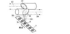
- FIG. 3 is a schematic diagram showing a positional relationship of optical axes of the optical system shown in FIG. 2. The figure which shows the measurement result of a reflection spectrum change when changing the height of a black PS resin piece.
- FIG. 1 is a configuration diagram of the main part of the resin identifying apparatus of the present embodiment
- FIG. 2 is a schematic perspective view of an optical system for infrared spectroscopic measurement of a sample
- FIG. 3 is an optical axis of the optical system shown in FIG. It is a schematic diagram which shows a positional relationship.
- This resin identification device includes a moving mirror that is reciprocally driven by a light source unit 1 including an infrared light source 11, condensing mirrors 12 and 14, an aperture 13, and the like, and a driving unit 24 including a half mirror 21, a fixed mirror 22, and a motor. 23, an infrared detector 4 such as an MCT (HgCdTe) detector, and an irradiation-side parabolic mirror that irradiates measurement light to a sample 8 placed and moved on a belt conveyor 7.
- a light source unit 1 including an infrared light source 11, condensing mirrors 12 and 14, an aperture 13, and the like
- a driving unit 24 including a half mirror 21, a fixed mirror 22, and a motor.
- an infrared detector 4 such as an MCT (HgCdTe) detector
- an irradiation-side parabolic mirror that irradiates measurement light to a sample 8 placed and moved on a belt conveyor 7.
- FIG. 1 (a) shows the entrance / exit optical system 3 and the belt conveyor 7 with the moving direction perpendicular to the paper surface, and FIG. 1 (b) shows the moving direction as the left-right direction.
- infrared light having a specific wavelength out of infrared interference light is absorbed, and other infrared light is reflected.
- the reflected light is sent to the infrared detector 4 via the incident / exit optical system 3, and the infrared detector 4 sends a detection signal corresponding to the intensity of the received light to the Fourier transform processing unit 5.
- the Fourier transform processing unit 5 obtains a reflection spectrum in a predetermined wavenumber range by Fourier transforming the detection signal and converting the time axis to the frequency axis. From this reflection spectrum, the resin type discriminating unit 6 is based on the reflection spectrum shape of one or a plurality of wave number regions in which a characteristic and typical spectrum shape reflecting the absorption spectrum of the resin to be identified is obtained. It is determined whether or not it matches the resin to be identified, and the resin type of the sample 8 is determined according to the determination result. In addition, for this determination, an absorption spectrum obtained by performing a Kramers-Kronig transform on the reflection spectrum can be used to determine the presence or absence of peaks at a plurality of specific wave numbers, and to determine the resin type according to the determination result. .
- the resin piece to be measured by Fourier transform infrared spectroscopy has an indefinite shape and the size is not constant. However, since the resin piece is crushed by a shredder, there is no extremely large size, and the size falls within a predetermined range, the minimum is 1 mm or less, and the maximum is about 6 mm. For this reason, the fluctuation
- the maximum fluctuation range of the sample height assumed at the measurement position is assumed to be ⁇ 3 mm.
- the angle formed by the optical axis of the light beam incident on the parabolic mirror and the optical axis of the light beam emitted from the parabolic mirror is 90.
- the parabolic mirror is used here because the infrared interference light introduced from the interferometer 2 to the incident / exit optical system 3 is a parallel light beam, the infrared interference light is a diffused light beam or a convergent light beam. In some cases, an ellipsoidal mirror is used instead of a parabolic mirror.
- the resin identification device of the present embodiment is characterized by the introduction optical axis S ⁇ b> 1 that is the optical axis of the light beam incident on the reflection surface of the irradiation side parabolic mirror 31 and the irradiation.
- a reflected optical axis S3, which is an optical axis of a light beam directed to the reflecting surface of the emitting side parabolic mirror 32, and a derived optical axis S4 that is reflected from the reflecting surface of the emitting side parabolic mirror 32 and becomes substantially parallel light are placed. This is a point where the plane Pout intersects the plane, not on the same plane. Therefore, these optical axes S1 to S4 do not fit in one plane and are developed three-dimensionally.
- the arrangement of the irradiation side parabolic mirror 31 and the emission side parabolic mirror 32 is determined so that the angle ⁇ formed by the incident optical axis S2 and the reflected optical axis S3 is in the range of 10 to 50 °. Yes. Therefore, when the two parabolic mirrors 31 and 32 have the same focal length, the numerical aperture NA of the parabolic mirrors 31 and 32 is in the range of 0.05 to 0.25. As will be described later, this is a numerical range derived experimentally so that a signal having a sufficient strength to determine the resin type of the sample 8 can be obtained even when the height of the sample 8 varies.
- the angle ⁇ formed by the incident optical axis S2 and the reflected optical axis S3 is 34.4 ° with respect to the ABS resin piece over the wave number range of 3500 to 500 cm ⁇ 1 and the wave number.
- the resin pieces to be measured were black, white large, and white yellow small, but a peak-like spectrum was measured in the vicinity of 2250 cm ⁇ 1 in any reflection spectrum. This is a peak due to the CN functional group unique to the ABS resin.
- the absorption by other components is small compared to the absorption by carbon to make the resin color black, so it is difficult to identify the black resin.
- determination part 6 it can be determined whether the measurement object sample is an ABS resin by determining the presence or absence of the peak derived from a CN functional group on a reflection spectrum.
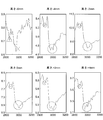
- FIG. 4 shows the result of measuring the reflection change (wave number region around 3000 cm ⁇ 1 ) due to the CH functional group peculiar to the PS resin when the sample height is changed for the black PS resin. Also at this time, the angle ⁇ formed by the incident optical axis S2 and the reflected optical axis S3 is 34.4 °, and the wave number resolution is 16 cm ⁇ 1 . From this figure, it can be seen that even in a black resin, which is generally considered difficult to measure, it is possible to observe a local change in reflectivity due to the CH functional group when the sample upper surface height is in the range of ⁇ 4 mm to +4 mm.
- the resin identification device uses the infrared light to identify the resin type. can do.
- the resin identification device is not limited to the embodiment described above, and can be variously modified.
- the introduction optical axis S1 and the derived optical axis S4 are located on substantially the same plane (that is, substantially the same height) and are substantially parallel, but the introduction optical axis S1.
- the derived optical axis S4 do not need to be on the same plane and do not need to be parallel. Therefore, not only the degree of freedom of the arrangement of the parabolic mirrors 31 and 32 is high, but also the degree of freedom of the positional relationship between the interferometer 2 and the infrared detector 4 and the incident / exit optical system 3 is high.
- the infrared interference part is installed before the sample is incident, but the same effect can be obtained even if it is installed after the sample is reflected.
Landscapes
- Physics & Mathematics (AREA)
- Spectroscopy & Molecular Physics (AREA)
- Health & Medical Sciences (AREA)
- Life Sciences & Earth Sciences (AREA)
- Chemical & Material Sciences (AREA)
- Analytical Chemistry (AREA)
- Biochemistry (AREA)
- General Health & Medical Sciences (AREA)
- General Physics & Mathematics (AREA)
- Immunology (AREA)
- Pathology (AREA)
- Investigating Or Analysing Materials By Optical Means (AREA)
Abstract
赤外干渉光をコンベア(7)上の試料(8)に照射する照射側放物面鏡(31)と試料(8)からの反射光を集光して赤外検出器へと送る出射側放物面鏡(32)とを、試料(8)の上方空間に配置し、照射側放物面鏡(31)への測定光の導入光軸(S1)と試料(8)への入射光軸(S2)とが載る平面と、試料(8)から出射側放物面鏡(32)へ向かう反射光の反射光軸(S3)と反射光の導出光軸(S4)とが載る平面とが、試料(8)上の測定点を含む直線で交差し、入射光軸(S2)と反射光軸(S3)とのなす角度が10~50°になるように各放物面鏡(31、32)の配置を定める。これにより、±3mm以上の高さ変動を許容しながら十分に光を取り込むことができ、試料(8)の樹脂種を判定するための反射スペクトルを高い感度、精度で取得できる。また、当該装置が不定形の樹脂片を搬送するベルトコンベア等の設置の支障にならずに済む。
Description
本発明は不定形状である樹脂の種類を識別する樹脂識別装置に関し、さらに詳しくは、赤外分光測定を用いて非接触で樹脂種類を識別する樹脂識別装置に関する。
エアコン、テレビ、洗濯機などの電気製品には、ポリプロピレン(PP)、ポリスチレン(PS)、アクリロニトリルブタジエンスチレン(ABS)といった様々な種類の樹脂が多用されている。そのため、廃棄製品から回収される樹脂片(シュレッダー片)には様々な種類の樹脂が混じっており、樹脂片を新たな製品のための材料として再利用するためには樹脂片を種類毎に選別する必要がある。
廃樹脂を再資源化するリサイクル工場では、小さく粉砕された樹脂片を効率よく種類毎に選別する必要があり、そのために、ベルトコンベアにより搬送される樹脂片の種類を赤外分光測定を利用して識別した上で分別する樹脂分別装置が知られている。例えば特許文献1に記載の分別装置では、試料(樹脂片)に赤外干渉光を照射し、その反射光を検出してフーリエ変換処理等の信号処理に供するが、試料の表面形状は不定であるため、通常の光学系では十分な強度の反射光を検出器に導入することが困難である。そのため、積分球形状の測定室を用い、反射光を集束させて検出器に導入する構成が採られている。
しかしながら、実際には、こうした球面鏡を用いて反射光を検出器の受光面に効率良く集光することは困難である。何故なら、一般にフーリエ変換赤外分光測定で利用される検出器の受光面の面積は小さく、特許文献1に記載されているような軸外し光学系で球面鏡を用いると、その非点収差のために光束が検出器の受光面からはみ出してしまうからである。こうした理由から、一般的な赤外分光光度計における反射測定装置では、ほぼ例外なく楕円面鏡や放物面鏡といった非球面鏡が光学系に利用されている(非特許文献1など参照)。
ところが、従来の一般的な反射測定装置用の光学系は試料の反射面の高さが固定されている(一定である)ことを前提としているのに対し、上述したような樹脂分別装置では、ベルトコンベアで搬送されて来る樹脂片の高さの変動が大きい。そのため、樹脂片の表面で拡散反射した光の集光効率はかなり低くなり、十分な精度で以て樹脂種類を識別することは困難である。また、従来の一般的な反射測定装置用の光学系では、試料の上方のほか試料の下方にも光学素子を配置する必要があり、ベルトコンベアなどの搬送機構を設置する障害となる。なお、この問題は、特許文献1のように積分球状の測定室を用いる場合にも同様である。
「分析計測機器 FTIR TALK vol.1(1990) 拡散反射法のイロハ」、株式会社島津製作所、[平成23年2月28日検索]、インターネット<URL : http://www.an.shimadzu.co.jp/ftir/support/lib/ftirtalk/talk1/intro.htm>
即ち、上述したような樹脂分別装置において樹脂片の種類を識別するためのフーリエ変換赤外分光測定装置の条件としては、試料の高さ及び表面形状が不定であっても効率良く拡散反射光を集光して検出器の受光面に導入することができること、光学系を構成する光学素子が試料を搬送する装置の設置やメンテナンスなどの障害にならないように配置されていること、が重要である。
本発明はこうした課題を解決するためになされたものであり、その主な目的は、順次搬送されて来る試料の高さが変動し表面形状が不定であっても試料からの拡散反射光を効率良く集光して高い感度及び精度の分光測定を実行することができ、それ故に樹脂種の識別能力を高めることができる樹脂識別装置を提供することである。また、本発明の別の目的は、試料からの拡散反射光を測定するための光学系がコンパクトで且つその配置が試料搬送装置等の障害にならないような赤外分光測定を利用した樹脂識別装置を提供することである。
上記課題を解決するために成された本発明は、測定位置に順次搬送されて来る樹脂片である試料に対し赤外干渉光を照射し、該試料からの反射光を検出しフーリエ変換を利用して得られた情報に基づいて該試料の樹脂種を判別する樹脂識別装置において、
赤外干渉光である測定光を反射させて試料に照射する照射側非球面鏡と、該試料からの反射光を反射させて検出器へ送る出射側非球面鏡と、を試料の上方空間に有し、
前記照射側非球面鏡へ導入される測定光の導入光軸とそれに対して該照射側非球面鏡で反射され試料に照射される測定光の入射光軸とが載る入射側平面と、前記試料に照射される測定光に対して該試料で反射され前記出射側非球面鏡へ向かう反射光の反射光軸とそれに対して該出射側非球面鏡で反射されて取り出される反射光の導出光軸とが載る出射側平面と、が交差するように、前記照射側非球面鏡及び前記出射側非球面鏡の配置が定められていることを特徴としている。
赤外干渉光である測定光を反射させて試料に照射する照射側非球面鏡と、該試料からの反射光を反射させて検出器へ送る出射側非球面鏡と、を試料の上方空間に有し、
前記照射側非球面鏡へ導入される測定光の導入光軸とそれに対して該照射側非球面鏡で反射され試料に照射される測定光の入射光軸とが載る入射側平面と、前記試料に照射される測定光に対して該試料で反射され前記出射側非球面鏡へ向かう反射光の反射光軸とそれに対して該出射側非球面鏡で反射されて取り出される反射光の導出光軸とが載る出射側平面と、が交差するように、前記照射側非球面鏡及び前記出射側非球面鏡の配置が定められていることを特徴としている。
従来の一般的な正反射測定装置や拡散反射測定装置における照射光学系及び出射光学系においては、上記入射側平面と上記出射側平面とが同一平面となっている。即ち、照射側光学系へ導入される測定光の導入光軸、それに対して該照射側光学系で反射され試料に照射される測定光の入射光軸、試料に照射される測定光に対して該試料で反射され出射光学系に向かう反射光の反射光軸、及びそれに対して該出射光学系で反射されて取り出される反射光の導出光軸、の全てが同一の平面上に載っている。
これに対し、本発明に係る樹脂識別装置では、入射側平面と出射側平面とは同一平面ではなく交差しており、その交差線上に試料の測定点(測定光が当たるとともに反射光が出射する点)が位置している。即ち、本発明に係る樹脂識別装置では、光路が2次元的ではなく立体的(3次元的)に展開されており、それによって、照射光学系及び出射光学系の光学素子を試料の上方空間にまとめて配置することが可能となる。
なお、本発明に係る樹脂識別装置で利用される非球面鏡としては、照射側非球面鏡に導入される測定光が平行光束(これは厳密な平行光束を意味するのではなくおおよそ平行である光束)である場合には放物面鏡を用いればよく、照射側非球面鏡に導入される測定光が発散光束や収束光束である場合には楕円面鏡を用いればよい。
照射側非球面鏡及び出射側非球面鏡の開口数NAは入射光軸と反射光軸とのなす角度に対応する。この開口数が小さいと取り込まれる反射光の光量が少なく感度が下がる。他方、開口数が大きいほど焦点深度が浅くなり、試料位置の上限変動、つまり高さ変動に対する許容範囲が狭くなる。そのため、測定位置における試料の高さ変動に対する許容範囲を或る程度確保しつつ、高感度、高精度の分光測定を実施するには、開口数を適宜の範囲に収める必要がある。一般的に、粉砕された樹脂片のサイズは1mm以下のものから6mm程度までであるから、識別時の試料の高さ変動は±3mm程度を想定すれば十分である。これに対応するには照射側非球面鏡及び出射側非球面鏡の開口数を0.05~0.2程度の範囲にすることが望ましく、そのためには入射光軸と反射光軸とのなす角度を10~50°程度の範囲に収めるようにするとよい。これにより、試料の高さ変動があっても十分な強度の反射光を検出器へ送ることができる。
本発明に係る樹脂識別装置では、入射側平面と出射側平面とは測定点を含む交差線で交差してさえいればよいから、前記導入光軸と前記導出光軸との位置関係の自由度は大きい。例えば、導入光軸と導出光軸とが同一平面上に載る構成とすることにより、照射側非球面鏡と出射側非球面鏡とが互いに近くに配置されるので、光学系をコンパクトにするのに有利である。一方、干渉計や検出器の位置によっては、照射側非球面鏡と出射側非球面鏡の配置高さをずらして導入光軸と導出光軸とが異なる平面上に載る構成としてもよい。
本発明に係る樹脂識別装置によれば、試料が不定形状でありその高さが変動する場合であっても、十分な強度の反射光を効率良く集めて検出器に送ることができる。それにより、様々な形状、サイズの樹脂片の種類を正確に識別することが可能となる。また、試料の下方側(背面側)に光学素子を配置する必要がなく、また試料と光学素子との間隔も十分に離すことができるので、例えば試料を測定位置に搬送するベルトコンベア等の搬送装置の設置に支障をきたさず、メンテナンス性も良好である。
本発明の一実施例である樹脂識別装置について、添付図面を参照して説明する。
図1は本実施例の樹脂識別装置の要部の構成図、図2は試料を赤外分光測定するための光学系の概略斜視図、図3は図2に示した光学系の光軸の位置関係を示す模式図である。
図1は本実施例の樹脂識別装置の要部の構成図、図2は試料を赤外分光測定するための光学系の概略斜視図、図3は図2に示した光学系の光軸の位置関係を示す模式図である。
この樹脂識別装置は、赤外光源11、集光鏡12、14、アパーチャ13などを含む光源部1と、ハーフミラー21、固定鏡22、モータ等からなる駆動部24により往復駆動される移動鏡23、を含む干渉計2と、MCT(HgCdTe)検出器等である赤外検出器4と、ベルトコンベア7上に載置されて移動する試料8に測定光を照射する照射側放物面鏡31、試料8からの反射光を取り出す出射側放物面鏡32、取り出された反射光を収束させつつ赤外検出器4へ送る集光鏡33などを含む入出射光学系3と、赤外検出器4で検出された信号を処理して反射スペクトルを算出するフーリエ変換処理部5と、反射スペクトルデータを用いて樹脂種を判別する樹脂種判別部6と、を備える。図1(a)は入出射光学系3及びベルトコンベア7をその移動方向を紙面に直交する方向として描いたものであり、図1(b)は移動方向を左右方向として描いた図である。
本実施例の樹脂識別装置の概略的な動作を説明する。光源部1から干渉計2に波数400~4000cm-1程度の範囲の赤外光が導入されると、干渉計2では、その赤外光がハーフミラー21で分割され、移動鏡23と固定鏡22とでそれぞれ反射されてハーフミラー21で再び合一されることで赤外干渉光が生成される。この赤外干渉光が入出射光学系3を介してベルトコンベア7上の試料8に照射される。試料8はシュレッダーダストと呼ばれる樹脂片であり、ベルトコンベア7により1個ずつ順次搬送される。試料8に含有される成分に応じて赤外干渉光のうちの特定の波長の赤外光は吸収され、それ以外の赤外光は反射する。この反射光は入出射光学系3を介して赤外検出器4に送られ、赤外検出器4は受光した光の強度に応じた検出信号をフーリエ変換処理部5へ送る。
赤外干渉光は時間経過に伴って強度が変化する光であるから、反射光も同様に強度変化する。そこで、フーリエ変換処理部5は検出信号をフーリエ変換して時間軸を周波数軸に変換することにより、所定の波数範囲の反射スペクトルを取得する。樹脂種判別部6はこの反射スペクトルから、識別すべき樹脂が有する吸収スペクトルを反映した特徴的且つ典型的なスペクトル形状が得られる1つ又は複数の波数域群の反射スペクトル形状を元に、前記識別すべき樹脂と一致するか否かを判定してその判定結果に応じて試料8の樹脂種を判断する。また、この判定には反射スペクトルをクラマース・クローニッヒ変換することで得られる吸収スペクトルを用い、複数の特定の波数におけるピークの有無を判定してその判定結果に応じて樹脂種を判定することもできる。
フーリエ変換赤外分光測定対象である樹脂片は不定形状であってサイズも一定ではない。ただし、樹脂片はシュレッダーにより破砕されたものであるため極端に大きなサイズのものはなく、サイズは或る所定の範囲、最小は1mm以下、最大でも6mm程度の範囲に収まる。このため、ベルトコンベア7上での試料8の上面の高さの変動も所定範囲内に収まる。ここでは、測定位置において想定される試料高さの最大変動幅を±3mmであるとしている。
照射側放物面鏡31及び出射側放物面鏡32はいずれも、その放物面鏡へ入射する光束の光軸と該放物面鏡から出射する光束の光軸とのなす角度が90°である軸外し角90°の放物面鏡である。ただし、ここでは干渉計2から入出射光学系3へ導入される赤外干渉光が平行光束であるために放物面鏡を用いているが、その赤外干渉光が拡散光束又は収束光束である場合には、放物面鏡の代わりに楕円面鏡を用いる。
本実施例の樹脂識別装置において特徴的であるのは、図2、図3に示すように、照射側放物面鏡31の反射面に入射する光束の光軸である導入光軸S1と照射側放物面鏡31の反射面から反射し集光されつつ試料8に照射される測定光の入射光軸S2とが載る平面Pinと、上記測定光に対して試料8上の測定点Qから発し出射側放物面鏡32の反射面に向かう光束の光軸である反射光軸S3と出射側放物面鏡32の反射面から反射されて略平行光になる導出光軸S4とが載る平面Poutとが、同一面上ではなく交差している点である。したがって、それら光軸S1~S4は1つの面内には収まらず、3次元的に展開されている。
また、入射光軸S2と反射光軸S3とのなす角度θが10~50°の範囲になるように、照射側放物面鏡31と出射側放物面鏡32との配置は定められている。したがって、2つの放物面鏡31、32が同一の焦点距離である場合には、それら放物面鏡31、32の開口数NAは0.05~0.25の範囲となる。これは、後述するように、試料8の高さ変動があった場合でも試料8の樹脂種を判別するのに十分な強度の信号が得られるように実験的に導出された数値範囲である。
本実施例の樹脂識別装置による測定例として、3500~500cm-1の波数範囲に亘るABS樹脂片に対して、入射光軸S2と反射光軸S3とのなす角度θを34.4°、波数分解能を16cm-1として測定した場合について説明する。測定対象の樹脂片は黒色、白色大、白黄色小であるが、いずれの反射スペクトルでも2250cm-1付近にピーク様のスペクトルが測定された。これはABS樹脂に特有のCN官能基によるピークである。一般に近赤外領域では、樹脂色を黒とするための炭素による吸収に比べて他の成分による吸収が小さいので、黒色の樹脂の識別は困難であるが、赤外光を用いた場合、黒色樹脂でも白色や白黄色の樹脂と同様にCN官能基の検出が可能であることが分かった。したがって、樹脂種判別部6では、反射スペクトル上でCN官能基に由来するピークの有無を判定することにより、測定対象試料がABS樹脂であるか否かを判定することができる。
図4は、黒色のPS樹脂を対象として試料高さを変えたときの、PS樹脂に特有なCH官能基による反射変化(波数域3000cm-1前後)を計測した結果である。このときも、入射光軸S2と反射光軸S3とのなす角度θは34.4°、波数分解能は16cm-1である。この図から、一般に測定が難しいと考えられる黒色樹脂においても、試料上面高さが-4mm~+4mmの範囲でCH官能基による反射率の局所変化を観測することが可能であることが分かる。即ち、その程度の試料高さ変動があっても、PS樹脂であるとの判定を行うために必要な情報が反射スペクトルから得られることが分かる。なお、入射光軸S2と反射光軸S3とのなす角度θを46.4°に変更して計測した結果においても、高さ許容の若干の低下はあるものの、同様にPS樹脂特有の官能基応答を識別できることが確認できた。
上述したように、近赤外光では反射スペクトルから樹脂種の識別が困難であると言われる黒色樹脂の場合でも、本発明に係る樹脂識別装置では赤外光を利用することから樹脂種を識別することができる。
本発明に係る樹脂識別装置は上述した実施例の形態に限らず、様々に変形することが可能である。例えば、上記実施例の構成では、導入光軸S1と導出光軸S4が略同一平面上に位置しており(つまりほぼ同じ高さであり)しかも略平行となっているが、導入光軸S1と導出光軸S4とは同一平面上である必要はなく、また平行である必要もない。したがって、放物面鏡31、32の配置の自由度が高いのみならず、干渉計2や赤外検出器4と入出射光学系3との位置関係の自由度も高い。また上記実施例では赤外干渉部をサンプル入射前に設置しているが,サンプル反射後に設置しても同様の効果が得られる。
また、上記実施例は本発明の一例にすぎないから、上記記載以外の点について、本発明の趣旨の範囲で適宜修正、追加、変更を加えても、本願特許請求の範囲に包含されることは明らかである。
1…光源部
11…赤外光源
12、14…集光鏡
13…アパーチャ
2…干渉計
21…ハーフミラー
22…固定鏡
23…移動鏡
24…駆動部
3…入出射光学系
31…照射側放物面鏡
32…出射側放物面鏡
33…集光鏡
S1…導入光軸
S2…入射光軸
S3…反射光軸
S4…導出光軸
4…赤外検出器
5…フーリエ変換処理部
6…樹脂種判別部
7…ベルトコンベア
8…試料
11…赤外光源
12、14…集光鏡
13…アパーチャ
2…干渉計
21…ハーフミラー
22…固定鏡
23…移動鏡
24…駆動部
3…入出射光学系
31…照射側放物面鏡
32…出射側放物面鏡
33…集光鏡
S1…導入光軸
S2…入射光軸
S3…反射光軸
S4…導出光軸
4…赤外検出器
5…フーリエ変換処理部
6…樹脂種判別部
7…ベルトコンベア
8…試料
Claims (4)
- 測定位置に順次搬送されて来る樹脂片である試料に対し赤外干渉光を照射し、該試料からの反射光を検出しフーリエ変換を利用して得られた情報に基づいて該試料の樹脂種を判別する樹脂識別装置において、
赤外干渉光である測定光を反射させて試料に照射する照射側非球面鏡と、該試料からの反射光を反射させて検出器へ送る出射側非球面鏡と、を試料の上方空間に有し、
前記照射側非球面鏡へ導入される測定光の導入光軸とそれに対して該照射側非球面鏡で反射され試料に照射される測定光の入射光軸とが載る入射側平面と、前記試料に照射される測定光に対して該試料で反射され前記出射側非球面鏡へ向かう反射光の反射光軸とそれに対して該出射側非球面鏡で反射されて取り出される反射光の導出光軸とが載る出射側平面と、が交差するように、前記照射側非球面鏡及び前記出射側非球面鏡の配置が定められていることを特徴とする樹脂種識別装置。 - 請求項1に記載の樹脂識別装置であって、
前記照射側非球面鏡及び前記出射側非球面鏡はそれぞれ、軸外し角90°の放物面鏡又は楕円面鏡であることを特徴とする樹脂識別装置。 - 請求項1又は2に記載の樹脂識別装置であって、
前記入射光軸と前記反射光軸とのなす角度が10°~50°の範囲内であることを特徴とする樹脂識別装置。 - 請求項1~3のいずれかに記載の樹脂識別装置であって、
前記導入光軸と前記導出光軸とが同一平面上に載っていることを特徴とする樹脂種識別装置。
Applications Claiming Priority (2)
| Application Number | Priority Date | Filing Date | Title |
|---|---|---|---|
| JP2011097735 | 2011-04-26 | ||
| JP2011-097735 | 2011-04-26 |
Publications (1)
| Publication Number | Publication Date |
|---|---|
| WO2012147717A1 true WO2012147717A1 (ja) | 2012-11-01 |
Family
ID=47072235
Family Applications (1)
| Application Number | Title | Priority Date | Filing Date |
|---|---|---|---|
| PCT/JP2012/060917 Ceased WO2012147717A1 (ja) | 2011-04-26 | 2012-04-24 | 樹脂識別装置 |
Country Status (2)
| Country | Link |
|---|---|
| TW (1) | TW201243314A (ja) |
| WO (1) | WO2012147717A1 (ja) |
Cited By (3)
| Publication number | Priority date | Publication date | Assignee | Title |
|---|---|---|---|---|
| CN103674868A (zh) * | 2013-12-18 | 2014-03-26 | 北京彤程创展科技有限公司 | 一种用分光光度计测定橡胶中二氧化硅含量的方法 |
| DE102016100689A1 (de) | 2015-01-30 | 2016-08-04 | Shimadzu Corporation | Harzidentifikationsvorrichtung |
| JP2019086412A (ja) * | 2017-11-07 | 2019-06-06 | 大日本印刷株式会社 | 検査システム、検査方法及び検査システムの製造方法 |
Citations (4)
| Publication number | Priority date | Publication date | Assignee | Title |
|---|---|---|---|---|
| JPH08300354A (ja) * | 1995-05-10 | 1996-11-19 | Hitachi Ltd | プラスチック分別装置 |
| JP2000180351A (ja) * | 1998-10-08 | 2000-06-30 | Nikon Corp | 光学特性測定ユニット |
| JP2007248129A (ja) * | 2006-03-14 | 2007-09-27 | Yanmar Co Ltd | 成分分析装置 |
| JP2008523392A (ja) * | 2004-12-09 | 2008-07-03 | ケーエルエー−テンカー テクノロジィース コーポレイション | 複数入射角分光散乱計システム |
-
2012
- 2012-04-24 WO PCT/JP2012/060917 patent/WO2012147717A1/ja not_active Ceased
- 2012-04-24 TW TW101114487A patent/TW201243314A/zh unknown
Patent Citations (4)
| Publication number | Priority date | Publication date | Assignee | Title |
|---|---|---|---|---|
| JPH08300354A (ja) * | 1995-05-10 | 1996-11-19 | Hitachi Ltd | プラスチック分別装置 |
| JP2000180351A (ja) * | 1998-10-08 | 2000-06-30 | Nikon Corp | 光学特性測定ユニット |
| JP2008523392A (ja) * | 2004-12-09 | 2008-07-03 | ケーエルエー−テンカー テクノロジィース コーポレイション | 複数入射角分光散乱計システム |
| JP2007248129A (ja) * | 2006-03-14 | 2007-09-27 | Yanmar Co Ltd | 成分分析装置 |
Cited By (5)
| Publication number | Priority date | Publication date | Assignee | Title |
|---|---|---|---|---|
| CN103674868A (zh) * | 2013-12-18 | 2014-03-26 | 北京彤程创展科技有限公司 | 一种用分光光度计测定橡胶中二氧化硅含量的方法 |
| DE102016100689A1 (de) | 2015-01-30 | 2016-08-04 | Shimadzu Corporation | Harzidentifikationsvorrichtung |
| US9903760B2 (en) | 2015-01-30 | 2018-02-27 | Shimadzu Corporation | Resin identification device |
| JP2019086412A (ja) * | 2017-11-07 | 2019-06-06 | 大日本印刷株式会社 | 検査システム、検査方法及び検査システムの製造方法 |
| JP7137772B2 (ja) | 2017-11-07 | 2022-09-15 | 大日本印刷株式会社 | 検査システム、検査方法及び検査システムの製造方法 |
Also Published As
| Publication number | Publication date |
|---|---|
| TW201243314A (en) | 2012-11-01 |
Similar Documents
| Publication | Publication Date | Title |
|---|---|---|
| JP5265632B2 (ja) | プラスチック等識別装置およびプラスチック等識別方法 | |
| AU780158B2 (en) | Method and apparatus for particle assessment using multiple scanning beam reflectance | |
| US11262242B2 (en) | Identification apparatus and sorting system | |
| JP4203916B2 (ja) | プラスチックの識別方法および識別装置 | |
| WO2012035785A1 (ja) | 臭素系難燃剤判定方法、臭素系難燃剤判定装置、リサイクル方法、及び、リサイクル装置 | |
| US20180172517A1 (en) | System for analyzing electromagnetic radiation, and device for producing same | |
| JP4932053B1 (ja) | ラマン散乱信号取得装置、ラマン散乱識別装置、ラマン散乱信号取得方法およびラマン散乱識別方法 | |
| US11099073B2 (en) | Identification apparatus, identification system, and resin-selecting system | |
| CN1221799C (zh) | 采用手持式红外光谱仪鉴定消费者或工业用过的废弃毡层的方法和装置 | |
| WO2019092772A1 (ja) | 赤外分光光度計用付属品 | |
| JP4260205B1 (ja) | ラマン散乱信号取得方法ならびにラマン散乱信号取得装置、および、プラスチックの識別方法ならびに識別装置 | |
| WO2012147717A1 (ja) | 樹脂識別装置 | |
| MXPA98000206A (en) | Identification of recirculable carpet materials using an infrared man spectrometer | |
| US9903760B2 (en) | Resin identification device | |
| JP2011226821A (ja) | 識別装置および識別方法 | |
| US20140145083A1 (en) | Plastic identification device | |
| JP5143175B2 (ja) | ラマン散乱に基づく識別方法および識別装置、並びにラマン散乱スペクトルの計測方法および計測装置 | |
| JP6187395B2 (ja) | 樹脂識別装置 | |
| JP6435930B2 (ja) | 樹脂種識別装置 | |
| JP2016024175A (ja) | 試料分析装置 | |
| JP2016045145A (ja) | 赤外分光測定装置 | |
| JPH02183147A (ja) | 微小異物検査装置 | |
| WO2025247758A1 (en) | Raman spectroscopy apparatus and method | |
| AU2024268621A1 (en) | Single point analyzer | |
| CN119269431A (zh) | 分析方法和复合分析装置 |
Legal Events
| Date | Code | Title | Description |
|---|---|---|---|
| 121 | Ep: the epo has been informed by wipo that ep was designated in this application |
Ref document number: 12777606 Country of ref document: EP Kind code of ref document: A1 |
|
| NENP | Non-entry into the national phase |
Ref country code: DE |
|
| 122 | Ep: pct application non-entry in european phase |
Ref document number: 12777606 Country of ref document: EP Kind code of ref document: A1 |
|
| NENP | Non-entry into the national phase |
Ref country code: JP |