WO2012147628A1 - 画像表示装置、立体表示システム、および画像表示方法 - Google Patents
画像表示装置、立体表示システム、および画像表示方法 Download PDFInfo
- Publication number
- WO2012147628A1 WO2012147628A1 PCT/JP2012/060633 JP2012060633W WO2012147628A1 WO 2012147628 A1 WO2012147628 A1 WO 2012147628A1 JP 2012060633 W JP2012060633 W JP 2012060633W WO 2012147628 A1 WO2012147628 A1 WO 2012147628A1
- Authority
- WO
- WIPO (PCT)
- Prior art keywords
- image
- eye
- display
- frame
- eye image
- Prior art date
- Legal status (The legal status is an assumption and is not a legal conclusion. Google has not performed a legal analysis and makes no representation as to the accuracy of the status listed.)
- Ceased
Links
Images



Classifications
-
- G—PHYSICS
- G09—EDUCATION; CRYPTOGRAPHY; DISPLAY; ADVERTISING; SEALS
- G09G—ARRANGEMENTS OR CIRCUITS FOR CONTROL OF INDICATING DEVICES USING STATIC MEANS TO PRESENT VARIABLE INFORMATION
- G09G3/00—Control arrangements or circuits, of interest only in connection with visual indicators other than cathode-ray tubes
- G09G3/001—Control arrangements or circuits, of interest only in connection with visual indicators other than cathode-ray tubes using specific devices not provided for in groups G09G3/02 - G09G3/36, e.g. using an intermediate record carrier such as a film slide; Projection systems; Display of non-alphanumerical information, solely or in combination with alphanumerical information, e.g. digital display on projected diapositive as background
- G09G3/003—Control arrangements or circuits, of interest only in connection with visual indicators other than cathode-ray tubes using specific devices not provided for in groups G09G3/02 - G09G3/36, e.g. using an intermediate record carrier such as a film slide; Projection systems; Display of non-alphanumerical information, solely or in combination with alphanumerical information, e.g. digital display on projected diapositive as background to produce spatial visual effects
-
- G—PHYSICS
- G02—OPTICS
- G02B—OPTICAL ELEMENTS, SYSTEMS OR APPARATUS
- G02B30/00—Optical systems or apparatus for producing three-dimensional [3D] effects, e.g. stereoscopic images
- G02B30/20—Optical systems or apparatus for producing three-dimensional [3D] effects, e.g. stereoscopic images by providing first and second parallax images to an observer's left and right eyes
- G02B30/22—Optical systems or apparatus for producing three-dimensional [3D] effects, e.g. stereoscopic images by providing first and second parallax images to an observer's left and right eyes of the stereoscopic type
- G02B30/24—Optical systems or apparatus for producing three-dimensional [3D] effects, e.g. stereoscopic images by providing first and second parallax images to an observer's left and right eyes of the stereoscopic type involving temporal multiplexing, e.g. using sequentially activated left and right shutters
-
- H—ELECTRICITY
- H04—ELECTRIC COMMUNICATION TECHNIQUE
- H04N—PICTORIAL COMMUNICATION, e.g. TELEVISION
- H04N13/00—Stereoscopic video systems; Multi-view video systems; Details thereof
- H04N13/10—Processing, recording or transmission of stereoscopic or multi-view image signals
- H04N13/106—Processing image signals
-
- H—ELECTRICITY
- H04—ELECTRIC COMMUNICATION TECHNIQUE
- H04N—PICTORIAL COMMUNICATION, e.g. TELEVISION
- H04N13/00—Stereoscopic video systems; Multi-view video systems; Details thereof
- H04N13/30—Image reproducers
- H04N13/332—Displays for viewing with the aid of special glasses or head-mounted displays [HMD]
- H04N13/341—Displays for viewing with the aid of special glasses or head-mounted displays [HMD] using temporal multiplexing
Definitions
- the present invention relates to an image display device, a stereoscopic display system, and an image display method for displaying a stereoscopic (3D) image by a frame sequential method (time division driving method).
- a frame sequential method that displays a left-eye image and a right-eye image in a time-sharing manner is a mainstream reproduction method.
- the liquid crystal display panel scans the pixels of the display unit line-sequentially.
- the eye images are presented twice.
- a display screen is viewed through shutter glasses, which are glasses for stereoscopic display observation, and a human binocular parallax is used to display a three-dimensional image.
- the shutter glasses have a left-eye shutter that closes and opens the left eye, and a right-eye shutter that closes and opens the right eye. Both shutters are controlled to be closed and opened in synchronization with the display frames of the respective images so that the left-eye image is input only to the left eye and the right-eye image is input only to the right eye. This allows the observer to recognize the left eye image and the right eye image separately.
- an image frame sequence is generated by adding an additional information image frame including additional information between a left eye image frame and a right eye image frame, and the image frame sequence is generated. Is displayed. Specifically, the display is performed in the order of the left-eye image frame, the additional information image frame, the right-eye image frame, the additional information image frame, and so on. Therefore, an observer who is not wearing shutter glasses can view additional information.
- shutter glasses When displaying the left-eye image frame, left-eye shutter: open, right-eye shutter: closed, When displaying the image frame for the right eye, the shutter for the left eye: closed, the shutter for the right eye: opened, When the additional information image frame is displayed, the shutter for the left eye: closed, the shutter for the right eye: closed, The opening / closing timing of both shutters is controlled so that Therefore, for the observer wearing the shutter glasses, both the shutters are closed when the additional information image frame is displayed, so that the additional information cannot be visually recognized.
- An observer who is not wearing shutter glasses can visually recognize a video in which images of several frames are added, that is, a video in which a left-eye image and a right-eye image overlap each other due to a visual integration effect. For this reason, a normal plane (2D) video cannot be presented to an observer who is not wearing shutter glasses.
- both the three-dimensional display for the spectacle wearer and the flat display for the non-spectacle wearer For example, when there are a large number of people, it is possible to simultaneously view a person who wears shutter glasses and appreciates a stereoscopic image and a person who appreciates flat images without wearing shutter glasses.
- Patent Document 1 also describes an example in which the additional information is information that hinders viewing of a stereoscopic image.
- the image of each additional information image frame is an inverted image of the left-eye image and an inverted image of the right-eye image.
- a solid gray image is displayed so that stereoscopic images cannot be observed.
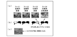
- FIG. 8 is a diagram for explaining an image visually recognized by an observer when a reverse image of the right-eye image is inserted.
- frames 4 are displayed in order.
- Frames 2 and 4 correspond to the additional information image frame described in Patent Document 1.
- the canceled images are halftone (50% gray), the left-eye image and the canceled image, that is, a video image in which the gray images overlap, as shown in FIG.
- the overall contrast is low. For this reason, it is not possible to present a good flat image to an observer who is not wearing shutter glasses.
- the present invention has been made in view of the above-described conventional problems, and its purpose is to provide a stereoscopic image for presentation to a wearer of shutter glasses without a double image for a non-wearer of shutter glasses.
- An object of the present invention is to provide an image display device, a stereoscopic display system, and an image display method that can be presented as a good flat image.
- an image display device of the present invention is an image display device that displays a left-eye image and a right-eye image for performing stereoscopic display by a time-division transmission method, and the current frame is When the left-eye image and the next frame are supplied to the image display device as the right-eye image, the right-eye image is canceled from the supplied left-eye image and right-eye image.
- the current frame is divided into n (n: an integer of 2 or more) first subframes, and the left-eye image is divided into 1st to (n-1) th first subframes.
- the interpolation image is assigned to the nth first subframe, the next frame is divided into n second subframes, and the right-eye image is assigned to the 1st to (n-1) th second subframes. Assign the interpolated image to the second subframe
- the 1st to nth first subframes and the 1st to nth second subframes are sequentially output as display frames in this order, and each display frame is output from the frame interpolation unit.
- a liquid crystal display panel that switches and displays each display frame on the display surface, a backlight that emits light from the back side of the liquid crystal display panel, and lighting, extinguishing, and brightness during lighting of the backlight
- a backlight control unit that controls the display surface, and the display surface includes a plurality of pixels.
- the backlight control unit includes the display period of the 1st to (n-1) th first subframes and the 1 to n
- the backlight is turned on at the reference value luminance
- the display period of the nth first subframe and the nth second subframe are displayed.
- the frame display period the backlight is turned on at a luminance of at least twice the reference value
- the frame interpolation unit is configured to turn on each of the first sub-pixels when the backlight is turned on at the luminance in each pixel.
- the interpolated image is generated such that the integral value of the luminance of all the images in the frame and each of the second subframes is 25% or more of the luminance of the image of the first first subframe. It is said.
- the image visually recognized by the observer who is not wearing the shutter glasses by the adjustment of the backlight brightness by the backlight control unit and the interpolation image generated by the frame interpolation unit is the left-eye image. Will be 25% more.
- the image for the right eye is cancelled.
- the image visually recognized by the observer can be output as an image while maintaining the dynamic range of the original image. Therefore, it is possible to observe an image that does not impair the sense of contrast. Therefore, it is possible to present a good flat image without a double image to a person who does not wear shutter glasses.
- the image display method of the present invention is an image display method for displaying a left-eye image and a right-eye image for performing stereoscopic display by a time-division transmission method, wherein the current frame is the left-eye image and the next frame.
- a first step of generating an interpolation image for canceling the right-eye image from the supplied left-eye image and the right-eye image Is supplied as the right-eye image, a first step of generating an interpolation image for canceling the right-eye image from the supplied left-eye image and the right-eye image;
- the frame is divided into n (n: integer greater than or equal to 2) first subframes, the left-eye image is assigned to the 1st to (n-1) th first subframes, and the interpolation is applied to the nth first subframe.
- the display surface includes a plurality of pixels.
- the display period of the 1st to (n-1) th first subframes and the display period of the 1st to (n-1) th second subframes The backlight is turned on at the reference value luminance, and the backlight is doubled from the reference value in the display period of the nth first subframe and the display period of the nth second subframe.
- the integrated value of the luminance of all the images of the first subframe and the second subframe is calculated in each pixel when the backlight is lit at the luminance.
- the interpolation image is generated so that the luminance of the image of the first first sub-frame is increased by 25% or more.
- the image visually recognized by the observer who is not wearing the shutter glasses by adjusting the luminance of the backlight and the generated interpolated image is an image obtained by increasing the left-eye image by 25%.
- the image for the right eye is cancelled.
- the image visually recognized by the observer can be output as an image while maintaining the dynamic range of the original image. Therefore, it is possible to observe an image that does not impair the sense of contrast. Therefore, it is possible to present a good flat image without a double image to a person who does not wear shutter glasses.
- the backlight control unit has the display period of the 1st to (n-1) th first subframes and the display of the 1st to (n-1) th second subframes.
- the backlight is lit at the luminance of the reference value, and the backlight is set to the reference value in the display period of the nth first subframe and the display period of the nth second subframe.
- the integral value of the luminances of all the images of each of the first sub-frame and the second sub-frame is turned on. Is a configuration for generating the interpolated image so that the luminance of the image of the first first sub-frame is increased by 25% or more.
- the image visually recognized by the observer who is not wearing the shutter glasses is an image obtained by increasing the left-eye image by 25%, and the right-eye image is cancelled.
- the image visually recognized by the observer can be output as an image while maintaining the dynamic range of the original image. Therefore, it is possible to observe an image that does not impair the sense of contrast. Therefore, there is an effect that it can be presented as a good flat image without a double image to a person who does not wear shutter glasses.
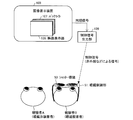
- FIG. 3 is a diagram illustrating a configuration example of the image display system according to the present embodiment.
- the image display system (stereoscopic display system) according to the present embodiment includes an image display device 100 that displays video and shutter glasses 50.
- the image display device 100 reproduces an image by a frame sequential method (time division transmission method).
- the shutter glasses 50 open and close the shutters provided in the two windows of the glasses in synchronization with the switching of the images displayed on the image display device 100.
- an observer who is not wearing the shutter glasses 50 can visually recognize a planar image (2D image).
- An observer wearing the shutter glasses 50 (referred to as an observer B) can view a stereoscopic image (3D image).
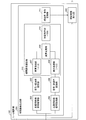
- FIG. 1 is a block diagram illustrating a configuration example of the image display apparatus 100 according to the present embodiment.
- the image display apparatus 100 includes a video signal receiving unit 101, a frame interpolation unit 102, a video signal processing unit 103, a drive signal control unit 104, a video display unit 105, a backlight control unit 106, and a backlight 107. And a spectacles control unit 108 (control signal generation unit).
- the image display device 100 is electrically connected to a control signal output unit 109 configured as an external device by a cable.
- the control signal output unit 109 can be provided in the image display device 100, but the communication direction with respect to the shutter glasses 50 can be freely changed by using an external device.
- the video signal receiving unit 101 receives a video signal supplied to the image display device 100.
- the video signal alternately includes a left-eye image and a right-eye image for performing stereoscopic display by a frame sequential method.
- the video signal receiving unit 101 outputs the received video signal to the frame interpolation unit 102. Further, the video signal receiving unit 101 may convert the video signal into a signal format that can be easily processed internally.
- the frame interpolation unit 102 generates an interpolated image for canceling a part with parallax from the image for the left eye and the image for the right eye acquired from the input video signal.
- the frame interpolation unit 102 uses a new frame sequence in which the generated interpolated image frame is inserted between the left-eye image frame and the right-eye image frame as a display frame as a video signal processing unit. To 103. A specific configuration of the frame interpolation unit 102 will be described later.
- the video signal processing unit 103 performs processing such as noise processing, gamma correction, and contour correction on the input video signal, that is, the image for the left eye, the image for the right eye, and the interpolation image of each display frame.
- the video signal processing unit 103 outputs the processed video signal to the drive signal control unit 104.
- the drive signal control unit 104 outputs the input video signal to the video display unit 105 and generates various drive signals corresponding to each display frame, and the video display unit 105, the backlight control unit 106, and the glasses control unit 108. Respectively.
- the various drive signals include a display drive signal (such as a start pulse signal) for driving the video display unit 105, a backlight drive signal for driving the backlight 107, and eyeglass drive for driving the shutter glasses 50. There are signals.
- the backlight drive signal and the eyeglass drive signal are generated according to the corresponding display frame image (one of the left-eye image, the right-eye image, and the interpolated image).
- the drive signal control unit 104 can control the operation timing of each unit at the timing of outputting various drive signals.
- the video display unit 105 displays an image (any one of a left-eye image, a right-eye image, and an interpolated image) represented by the input video signal.
- the video display unit 105 is realized as a liquid crystal display panel.
- the liquid crystal display panel has a display surface composed of a plurality of pixels. Therefore, the video display unit 105 switches each display frame on the display surface at high speed by rewriting the gradation voltage applied to the pixel at high speed each time each display frame is output from the drive signal control unit 104. is doing.
- the liquid crystal display panel only needs to have an active matrix type configuration, for example.
- the backlight control unit 106 controls turning on / off of the backlight 107 and luminance at the time of lighting according to the backlight driving signal output from the driving signal control unit 104.
- the backlight control unit 106 drives the backlight 107 by supplying a drive voltage (drive current).
- the backlight 107 is disposed on the back surface of the video display unit 105.
- the backlight 107 emits light from the back side of the video display unit 105.
- the backlight 107 may be, for example, a direct type or may be configured by an LED array.
- the spectacles control unit 108 generates a control signal for controlling the open / close state of each shutter of the shutter spectacles 50 in accordance with the spectacles drive signal output from the drive signal control unit 104. By the control signal, it is possible to notify which of the left-eye image, the right-eye image, and the interpolated image is displayed on the display surface.
- the eyeglass control unit 108 outputs the generated control signal to the control signal output unit 109.
- the control signal output unit 109 outputs the input control signal to the outside as a wireless signal such as an infrared ray or a radio wave.
- the control signal output unit 109 and the glasses control unit 51 (open / close switching unit) of the shutter glasses 50 constitute a wireless communication system.
- the interpolated image is generated such that when the backlight 107 is turned on, the integrated value of the luminance of all the images of frames 1 to 4 is increased by 25% of the luminance of the image of frame 1 at each pixel. is doing.
- the video display unit 105 is a normally black type, and the luminance is 0% for black and white for the plus direction.
- the luminance of such an interpolated image can be obtained by the following equation (1).
- (F 1 ⁇ 1.5) ⁇ (F 3 ⁇ 0.5) + 50 A
- F 1 Luminance [%] of the image for the left eye of frame 1
- F 3 Brightness [%] of the image for the right eye of frame 3
- A Luminance of interpolation image [%]
- the luminance of the interpolation image is 75% according to the above equation (1).
- the reason for the “25% increase” as described above is as follows. For example, in the case of a stereoscopic image with very high contrast such as a starry sky, if a pixel in frame 1 is black (luminance: 0%) and the same pixel in frame 3 is white (luminance: 100%), frame 2 , 4 even if the same pixel is black (luminance: 0%), the integrated value of the luminance of the four frames is 25%. That is, since this value becomes the base of black, it cannot be lowered below this value.
- white luminance when 25% luminance is based on black, white luminance must be 125% in order to maintain the dynamic range.
- Luminance: 200% can be achieved by irradiating white (luminance: 100%) pixels with a backlight 107 that is lit at twice the normal brightness.
- the brightness of the corrected image is calculated in units of pixels, and the brightness of the backlight 107 is also controlled so that the average output of the four frames is output as a video while maintaining the dynamic range of the original image. Yes.
- the observer A who is not wearing the shutter glasses 50 can observe an image that does not impair the contrast.
- the luminance of the backlight 107 during the interpolated image display period is not limited to twice, and may be greater than twice. However, if it is larger than twice, the dynamic range can be maintained, but the power consumption increases, so care must be taken.
- the frame interpolation unit 102 generates a corrected image so that the corrected image at the time of display has the above-described luminance, and the backlight control unit 106 adjusts the luminance when the backlight 107 is lit. .
- the configuration of the frame interpolation unit 102 will be described.
- the video display unit 105 is driven at 4 ⁇ speed to display four display frames (frame 1: left eye image, frame 2: interpolation image, frame 3: right eye image, frame 4: interpolation image).
- frame 1 left eye image
- frame 2 interpolation image
- frame 3 right eye image
- frame 4 interpolation image
- FIG. 2 is a block diagram showing an example of the configuration of the frame interpolation unit 102.
- the frame interpolation unit 102 includes an interpolation image generation unit 201 that generates an interpolation image, and an interpolation image generated by the interpolation image generation unit 201 by using a left-eye image frame and a right-eye image frame. And an interpolated image insertion unit 202 for outputting as a new frame sequence.
- the interpolated image generation unit 201 generates an interpolated image that cancels the right-eye image from the acquired left-eye image and right-eye image. Specifically, the interpolation image generation unit 201 generates an interpolation image by calculating the luminance of the interpolation image for each pixel.
- the interpolated image generation unit 201 includes a left-eye video signal acquisition unit 203, a right-eye video signal acquisition unit 204, a signal-transmittance conversion unit 205, a signal-transmittance conversion unit 206, a multiplication processing unit 207, and a multiplication processing unit 208.
- the left-eye video signal acquisition unit 203 acquires a left-eye video signal from the video signal input to the frame interpolation unit 102.
- the video signal for the left eye represents a left eye image, and the luminance of each pixel is composed of, for example, 8-bit data (256 gradations).
- the left-eye video signal acquisition unit 203 outputs the left-eye video signal to the signal-transmittance conversion unit 205.
- the right-eye video signal acquisition unit 204 acquires a right-eye video signal from the video signal input to the frame interpolation unit 102.
- the video signal for the right eye represents the image for the right eye, and the luminance of each pixel is composed of, for example, 8-bit data (256 gradations).
- the right-eye video signal acquisition unit 204 outputs the right-eye video signal to the signal-transmittance conversion unit 206.
- the signal-transmittance conversion unit 205 converts the input video signal for the left eye into a transmittance, and outputs the transmittance to the multiplication processing unit 207.
- the signal-transmittance conversion unit 206 converts the input video signal for the right eye into a transmittance, and outputs the transmittance to the multiplication processing unit 208.
- the signal-transmittance conversion unit 205 sets the transmittance of black (one gradation) to 0% and the transmittance of white (256 gradations) to 100%.
- the multiplication processing unit 207, the multiplication processing unit 208, the subtraction processing unit 209, and the addition processing unit 210 constitute an interpolation image calculation unit 212 that calculates an interpolation image using the above equation (1).
- the interpolated image calculation unit 212 calculates the image transmittance corresponding to the luminance of the image.
- the multiplication processing unit 207 multiplies the input transmittance by 1.5 and outputs it to the subtraction processing unit 209.
- the multiplication processing unit 208 multiplies the input transmittance by 0.5 and outputs it to the subtraction processing unit 209.
- the subtraction processing unit 209 outputs a value obtained by subtracting the transmittance output from the multiplication processing unit 208 from the transmittance output from the multiplication processing unit 207 to the addition processing unit 210.
- the subtraction value here may be a negative value.
- the addition processing unit 210 outputs a value obtained by adding 50% to the input transmittance to the transmittance-signal conversion unit 211.
- the transmittance-signal conversion unit 211 converts the input transmittance into a video signal, and outputs the video signal to the interpolation image insertion unit 202.
- the video signal converted and generated by the transmittance-signal converter 211 represents an interpolated image.
- the transmissivity-signal conversion unit 211 converts the transmissivity of 1 ⁇ 2 into the corresponding gradation in order to remove the luminance of the backlight 107. For example, when the input transmittance is 180%, it is converted to white of 244 gradations corresponding to 90%.
- the interpolation image insertion unit 202 receives the video signal indicating the left-eye image and the right-eye image input to the frame interpolation unit 102 and the video signal indicating the interpolation image output from the transmittance-signal conversion unit 211. You are typing.
- the interpolation image insertion unit 202 does not simply insert the frame of the interpolation image, but changes the frame rate to generate a new frame sequence.
- the frame for the left eye image and the frame for the right eye image input to the frame interpolation unit 102 correspond to the double speed driving, and the display frame (frame 1: frame 1) output from the interpolation image insertion unit 202.
- the image for the left eye, frame 2: the interpolated image, frame 3: the image for the right eye, and frame 4: the interpolated image) correspond to quadruple speed driving.
- the shutter glasses 50 are also called active shutter glasses, and have a left-eye shutter that closes and opens the left eye and a right-eye shutter that closes and opens the right eye, as shown in FIG.
- the left-eye shutter and the right-eye shutter contain liquid crystal molecules inside, and the opening / closing of the shutter can be controlled by changing the alignment state of the liquid crystal molecules. That is, when the shutter is open, the viewer's eyes can see the display image of the video display unit 105, but nothing is visible when the shutter is closed.
- the shutter glasses 50 include a glasses control unit 51.
- the spectacles control unit 51 receives the control signal transmitted from the control signal output unit 109, and switches between the open / closed states of the left-eye shutter and the right-eye shutter based on the received control signal.
- the control signal indicates display of the image for the left eye
- the glasses control unit 51 opens the shutter for the left eye and closes the shutter for the right eye.
- the control signal indicates the display of the image for the right eye
- the glasses control unit 51 opens the shutter for the right eye and closes the shutter for the left eye.
- the control signal indicates display of the interpolated image
- the spectacles control unit 51 closes the left-eye shutter and the right-eye shutter.
- the video signal receiving unit 101 receives the supplied video signal.
- the video signal received by the video signal receiving unit 101 includes left-eye images and right-eye images alternately.
- Corresponding to the double speed driving are set as a left eye image frame, a right eye image frame, a left eye image frame, a right eye image frame,. .
- the video signal receiving unit 101 outputs the received video signal to the frame interpolation unit 102. That is, the video signal receiving unit 101 sequentially outputs each image to the frame interpolation unit 102.
- the frame interpolation unit 102 acquires a left-eye video signal and a right-eye video signal from the supplied video signal, and generates an interpolation image from the left-eye image and the right-eye image. Specifically, the frame interpolation unit 102 sequentially generates one interpolation image from one set of the left-eye image of the odd-numbered frames and the right-eye image of the even-numbered frames. That is, an interpolated image is generated from the frame k and the frame k + 1, subsequently an interpolated image is generated from the frame k + 2 and the frame k + 3, and then the interpolated image is similarly generated up to the final frame.
- the frame interpolation unit 102 inserts the generated interpolation image into two places, immediately after the left-eye image used to generate the interpolation image and immediately after the right-eye image used to generate the interpolation image. To do. Specifically, the frame interpolation unit 102 inserts the interpolation image generated from the frame k and the frame k + 1 immediately after the frame k and immediately after the frame k + 1, and subsequently, the interpolation generated from the frame k + 2 and the frame k + 3. The image is inserted immediately after the frame k + 2 and immediately after the frame k + 3, and then the interpolation image is similarly inserted until the last frame.
- the term “immediately after” refers to the interval between the current frame and the next frame.
- a new display frame sequence corresponding to 4 ⁇ speed driving is generated.
- the frame interpolation unit 102 sequentially outputs the display frames to the video signal processing unit 103.
- the video signal processing unit 103 removes noise from the input video signal, that is, the image (the image for the left eye, the image for the right eye, the interpolation image), After performing processing such as gamma correction and contour correction, the signal is output to the drive signal control unit 104.
- the driving signal control unit 104 generates various driving signals every time a display frame is input. Then, the drive signal control unit 104 outputs the video signal of the display frame to the video display unit 105 and outputs the generated various drive signals.
- the drive signal control unit 104 drives the backlight in synchronization with the display drive signal for driving the display of the display frame n and the display of the display frame n.
- a glasses driving signal for driving the shutter glasses 50 is generated in synchronization with the backlight driving signal and display of the display frame n.
- the drive signal control unit 104 outputs the video signal of the display frame and the display drive signal to the video display unit 105, outputs the backlight drive signal to the backlight control unit 106, and sends the glasses drive signal to the glasses control unit 108. Output.
- the drive signal control unit 104 operates.
- the backlight drive signal is set so that the backlight 107 is lit at the brightness of the normal reference value when the display frame is the image for the left eye or the image for the right eye.
- the backlight drive signal is set to turn on the backlight 107 with a luminance twice as high as the reference value.
- the video display unit 105 switches and displays each display frame on the display surface.
- the backlight 107 is lit with a predetermined luminance in synchronization with the display of the display frame.
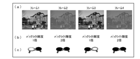
- FIG. 4 is a diagram for explaining a state when the video display unit 105 displays a display frame.
- four display frames (frame 1: left eye image, frame 2: interpolation image, frame 3: right eye image, frame 4: interpolation image) are displayed in order.
- the backlight 107 lights up with a luminance of 1 time in the frames 1 and 3 and 2 times in the frames 2 and 4.
- the spectacles control unit 108 that receives the spectacles driving signal generates a control signal and outputs it to the control signal output unit 109.
- the spectacles control part 51 which received the radio signal transmitted from the control signal output part 109 is switching the opening / closing state of the shutter of the shutter spectacles 50 based on the received radio signal.
- the shutter glasses 50 the shutter for the left eye is opened and the shutter for the right eye is closed in synchronization with the display of the frame 1.
- the left-eye shutter is closed and the right-eye shutter is open.
- both the left-eye shutter and the right-eye shutter are closed.
- Video display Next, an image viewed by the observer A and an image viewed by the observer B with respect to the display of the four display frames shown in FIG. 4 will be described.
- the observer A is watching the video displayed by the image display device 100 without passing through the shutter glasses 50 (see FIG. 3). Therefore, the observer A observes all images of the four display frames with both eyes.
- FIG. 5 shows an image visually recognized by the viewer A.
- FIG. 5 shows two conventional displays as a comparison with the present embodiment in addition to the display of the present embodiment.
- both the left eye image and the right eye image are canceled out.
- the image visually recognized by the viewer A is a 50% gray image.
- the image visually recognized by the viewer A is an image obtained by adding a 50% gray image to the left eye image.
- This image is an image with half the contrast.
- an image having a low contrast as a whole has been obtained.
- the inventors of the present invention have found that the reason why the contrast is lowered is that, in the method of simply canceling with an inverted image, a 50% gray image comes in as a result of cancellation, so this frame accounts for 50% of the total It has been found that the contrast is reduced by 25% both in the upper and lower directions, and as a result, the contrast becomes 50%.
- the interpolated image is displayed so that the image for the left eye is increased by 25%. Synthesizing.
- the video visually recognized by the viewer A is a video obtained by increasing the left-eye image by 25%.
- the image for the right eye is cancelled.
- the luminance of the interpolated image is set in units of pixels so that the average output of the four display frames is output as a video while maintaining the dynamic range of the original video instead of a simple inverted image.
- the calculation is performed and the brightness of the backlight 107 is controlled. As a result, it is possible to observe an image that does not impair the contrast. Therefore, it is possible to visually recognize a good flat image without a double image.
- the observer B views the video displayed by the image display device 100 through the shutter glasses 50 (see FIG. 3). Therefore, the observer B observes the image for the left eye only with the left eye and observes the image for the right eye only with the right eye. The interpolated image is not observed by the observer B. Therefore, the observer B can visually recognize the image stereoscopically by binocular parallax.
- the viewer B wearing the shutter glasses 50 presents a comfortable stereoscopic image that is the same as the conventional one, and the viewer A not wearing the shutter glasses 50 receives 2 It is possible to present a good flat image without overlapping images.
- the above-described image display device 100 displays four display frames (frame 1: left-eye image, frame 2: interpolation image, frame 3: right-eye image, frame 4: interpolation image) by quadruple speed driving.
- the interpolated image is set so that the integrated value of the luminance of all the images of the frames 1 to 4 is increased by 25% of the luminance of the image of the frame 1 at each pixel.
- the first frame supplied to the image display device 100 is not limited to the left-eye image, but may be the right-eye image. In any case, the left-eye image and the right-eye image are supplied alternately.
- 25% is the lowest value and can be set larger than 25%.
- it is necessary to increase the luminance of the backlight 107 attention is necessary from the viewpoint of power consumption.
- the display frame switching is not limited to 4 ⁇ speed driving.
- double speed driving of 2 ⁇ n (n: an integer of 3 or more) or more is theoretically possible.
- the original frame may be divided into three subframes and output as a display frame.
- display frames are generated in the order of left eye, left eye, interpolation, right eye, right eye, and interpolation.
- the frame interpolation unit 102 divides the current frame into n (n: integer greater than or equal to 2) first subframes, and 1st to (n-1) th first subframes.
- the interpolated image is assigned to the nth first subframe of the current frame image, the next frame is divided into n second subframes, and the next frame image is divided into 1 to n ⁇ 1 second subframes.
- n integer greater than or equal to 2
- the next frame image is divided into 1 to n ⁇ 1 second subframes.
- the 1st to nth first subframes and the 1st to nth second subframes are sequentially output as display frames in this order.
- an interpolation image generation method for canceling parallax is basically the same as the generation method in the case of quadruple speed driving.
- the backlight control unit 106 can drive the backlight 107 according to the structure of the backlight 107.
- the backlight control unit 106 may drive the backlight 107 so that the backlight 107 is turned on and off simultaneously on the entire display surface, or the backlight 107 is turned on and off.
- the backlight 107 can be driven so as to be partially sequentially performed on the surface.
- the backlight 107 can be driven by scanning the light source in synchronization with scanning of one line or a plurality of lines of pixels on the display surface. Thereby, the display quality of a three-dimensional image can be improved.
- the image display apparatus has the same configuration as that of the image display apparatus 100 shown in FIG. 1 except for the configuration of the frame interpolation unit 102. Therefore, the configuration of the frame interpolation unit 102 will be mainly described below. Configurations other than those described in the present embodiment are the same as those in the first embodiment. For convenience of explanation, members having the same functions as those shown in the drawings of the first embodiment are given the same reference numerals, and explanation thereof is omitted.
- the frame interpolation unit 102 according to the first embodiment has a configuration for obtaining the luminance of the interpolated image by calculating a calculation formula.
- the frame interpolation unit 102 according to the present embodiment uses an LUT (look-up table). Referring to, a configuration for reading the luminance of the interpolated image is provided.
- FIG. 6 is a block diagram illustrating another configuration example of the frame interpolation unit 102.
- the frame interpolation unit 102 includes an interpolation image generation unit 301 that generates an interpolation image, and an interpolation image generated by the interpolation image generation unit 301 as a left-eye image frame and a right-eye image frame. And an interpolated image insertion unit 302 that outputs as a new frame sequence.
- the interpolated image generation unit 301 generates an interpolated image for canceling the parallax from the acquired left-eye image and right-eye image. Specifically, the interpolation image generation unit 301 generates an interpolation image by reading the luminance of the interpolation image from the LUT for each pixel.
- the interpolation image generation unit 301 includes a left-eye video signal acquisition unit 303, a right-eye video signal acquisition unit 304, an interpolation image conversion unit 305 (interpolation image reading unit), an LUT 306, and a linear interpolation unit 307.
- the left-eye video signal acquisition unit 303 acquires a left-eye video signal from the video signal input to the frame interpolation unit 102.
- the video signal for the left eye represents a left eye image, and the luminance of each pixel is composed of, for example, 8-bit data (256 gradations).
- the left-eye video signal acquisition unit 303 outputs the left-eye video signal to the interpolated image conversion unit 305.
- the right-eye video signal acquisition unit 304 acquires a right-eye video signal from the video signal input to the frame interpolation unit 102.
- the video signal for the right eye represents the image for the right eye, and the luminance of each pixel is composed of, for example, 8-bit data (256 gradations).
- the right-eye video signal acquisition unit 304 outputs the right-eye video signal to the interpolation image conversion unit 305.
- the interpolated image conversion unit 305 reads the pixel value of the interpolated image with reference to the LUT 306 from the pixel value of the left eye image and the pixel value of the right eye image for each pixel.
- the pixel value (luminance) of the interpolated image set according to the combination of the pixel value (luminance) of the left-eye image and the pixel value (luminance) of the right-eye image supplied to the image display device 100. ) Is stored.
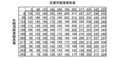
- FIG. 7 shows an example of the LUT 306.
- the values shown in FIG. 7 calculate combinations of pixel values that are 0%, 10%, 20%,... 100% when the relationship (gamma) between the video signal and the output luminance is 2.2. That is what was sought.
- the linear interpolation unit 307 generates a pixel value to be output by linear interpolation with respect to a combination of pixel values not stored in the LUT 306. For example, when the pixel value of the left-eye image is 100 and the pixel value of the right-eye image is 200, the pixel values 90 and 123 of the left-eye image and the pixel value 186 of the right-eye image stored in the LUT 306 are stored. Using four values 123, 116, 142, and 136 (upper left, lower left, upper right, and lower right) that intersect with 202, linear interpolation is used. The linear interpolation unit 307 outputs the video signal of the interpolation image thus generated to the interpolation image insertion unit 302.
- the interpolation image insertion unit 302 receives the video signal indicating the left-eye image and the right-eye image input to the frame interpolation unit 102 and the video signal indicating the interpolation image output from the linear interpolation unit 307. Yes.
- the interpolation image insertion unit 302 does not simply insert the frame of the interpolation image, but generates a new frame sequence by changing the frame rate.
- the left-eye image frame and the right-eye image frame input to the frame interpolation unit 102 correspond to double-speed driving
- the display frame output from the interpolation image insertion unit 302 is quad-speed. It corresponds to driving.
- the frame interpolation unit 102 obtains the luminance of the interpolated image by reading it with reference to the LUT instead of obtaining it by calculation. Therefore, signal delay can be suppressed as compared with the case of performing the arithmetic processing of the first embodiment.
- the current frame is supplied to the image display device as the right eye image instead of the left eye image, and the next frame is supplied as the left eye image instead of the right eye image.
- the frame interpolation unit generates an interpolation image for canceling the left-eye image from the supplied right-eye image and the left-eye image, and then converts the current frame into the n first frames.
- the right-eye image is assigned to the 1st to (n-1) th first subframes
- the interpolated image is assigned to the nth first subframe
- the next frame is divided into n second subframes.
- the left eye image may be assigned to the 1st to (n-1) th second subframes
- the interpolated image may be assigned to the nth second subframe.
- the frame interpolation unit includes an interpolation image generation unit that calculates the luminance of each pixel of the interpolation image and generates the interpolation image.
- the interpolation image generation unit calculates the luminance of each pixel of the interpolation image by using the transmittance of the left eye image and the transmittance of the right eye image. It is preferable that an interpolation image calculation unit is provided.
- the luminance of each pixel of the interpolated image can be calculated with high accuracy.
- the interpolated image calculation unit is provided for each pixel.
- (F 11 ⁇ 1.5) ⁇ (F 21 ⁇ 0.5) + 50 A
- F 11 Transmittance [%] of the image of the first first subframe
- F 21 Transmittance [%] of the image of the first second subframe
- the interpolated image generation unit includes the interpolation set according to a combination of the luminance of the left-eye image and the luminance of the right-eye image supplied to the image display device.
- Lookup table for storing the luminance of the image, and interpolation for reading out the luminance of the interpolated image from the lookup table based on the luminance of the supplied image for the left eye and the image for the right eye for each pixel.
- an image reading unit is an image reading unit.
- signal delay can be suppressed as compared with the case where the luminance of each pixel of the interpolated image is obtained by calculation.
- the backlight control unit drives the backlight so that the backlight is turned on and off all at once on the entire display surface.
- the backlight control unit drives the backlight so that the backlight is turned on and off partially sequentially with respect to the display surface.
- the backlight can be driven by scanning the light source in synchronization with scanning of one line or a plurality of lines of pixels on the display surface.
- the display quality of a three-dimensional image can be improved.
- a control signal is generated that indicates whether an image of a display frame to be displayed on the display screen is the left-eye image, the right-eye image, or the interpolated image. It is preferable to further include a control signal generation unit.
- control signal can be suitably used as a control signal for switching the open / close state of the shutter of the shutter glasses for stereoscopic display ornamentation.
- the three-dimensional display system of the present invention is configured to display the open / closed states of the image display device, shutter glasses having a left-eye shutter and a right-eye shutter, and the left-eye shutter and the right-eye shutter on the display surface.
- An open / close switching unit that switches in synchronization with the display of each display frame, and the open / close switching unit is for the left eye when the image of the display frame displayed on the display surface is the image for the left eye. Only the shutter is opened. When the image is for the right eye, only the shutter for the right eye is opened. When the image is the interpolated image, the shutter for the left eye and the shutter for the right eye are closed.
- the observer wearing the shutter glasses can visually recognize the image stereoscopically by binocular parallax. Further, in the image display device, a comfortable stereoscopic image that is the same as the conventional one is presented to an observer wearing the shutter glasses, and there is no double image for an observer who is not wearing the shutter glasses. A good plane image can be presented.
- an interpolation image for canceling the left-eye image is generated from the supplied right-eye image and left-eye image, and in the second step, the current frame is converted into n first frames.
- the right-eye image is assigned to the 1st to (n-1) th first subframes
- the interpolated image is assigned to the nth first subframe
- the next frame is divided into n second subframes.
- the left eye image may be assigned to the 1st to (n-1) th second subframes
- the interpolated image may be assigned to the nth second subframe.
- the present invention can be suitably used not only in a field related to an image display device that displays a stereoscopic video by a frame sequential method, but also in a field related to an image display method. it can.
- Shutter glasses 51 Glasses control unit (open / close switching unit) DESCRIPTION OF SYMBOLS 100 Image display apparatus 101 Video signal receiving part 102 Frame interpolation part 103 Video signal processing part 104 Drive signal control part 105 Video display part (liquid crystal display panel) 106 Backlight Control Unit 107 Backlight 108 Eyeglass Control Unit (Control Signal Generation Unit) 109 Control signal output unit 201, 301 Interpolated image generation unit 202, 302 Interpolated image insertion unit 203, 303 Left eye video signal acquisition unit 204, 304 Right eye video signal acquisition unit 205 Signal-transmittance conversion unit 206 Signal-transmission Rate conversion unit 211 Transmittance-signal conversion unit 212 Interpolated image calculation unit 305 Interpolated image conversion unit (interpolated image reading unit) 306 LUT 307 Linear interpolation unit
Landscapes
- Engineering & Computer Science (AREA)
- Physics & Mathematics (AREA)
- Multimedia (AREA)
- Signal Processing (AREA)
- General Physics & Mathematics (AREA)
- Computer Hardware Design (AREA)
- Theoretical Computer Science (AREA)
- Optics & Photonics (AREA)
- Testing, Inspecting, Measuring Of Stereoscopic Televisions And Televisions (AREA)
- Control Of Indicators Other Than Cathode Ray Tubes (AREA)
Abstract
画像表示装置(100)は、第1サブフレームの左眼用と第2サブフレームの右眼用との画像の表示期間に、バックライト(107)を基準値の輝度で点灯させ、第1~2のサブフレームの補間画像の表示期間に、基準値の2倍以上の輝度で点灯させるバックライト制御部(106)と、上記点灯時に、第1~2サブフレームの全画像の輝度の積分値が、1番目の第1サブフレームの画像の輝度の25%増以上となるようにするフレーム補間部(102)とを備える。
Description
本発明は、フレームシーケンシャル方式(時分割駆動方式)で、立体(3D)映像を表示する画像表示装置、立体表示システム、および画像表示方法に関するものである。
昨今、液晶表示装置などの画像表示装置において、立体映像を表示する映像表示技術が提案されている。このような画像表示装置では、左眼用画像と右眼用画像とを時分割で表示するフレームシーケンシャル方式が、再生方式として主流となっている。例えば、一般に、フレームシーケンシャル方式の液晶テレビでは、液晶表示パネルは表示部の画素を線順次スキャンしているので、映像の表示を早くするために、4倍速駆動をして左眼用画像と右眼用画像とを2回ずつ提示している。フレームシーケンシャル方式では、立体表示観察用の眼鏡であるシャッター眼鏡を通して表示画面を見ることで、人間の両眼視差を利用して、映像を立体的に見せている。
シャッター眼鏡は、左眼を閉鎖および開放する左眼用シャッターと、右眼を閉鎖および開放する右眼用シャッターとを有している。両シャッターは、左眼用画像が左眼のみに入力し、右眼用画像が右眼のみに入力するように、各画像の表示フレームに同期して閉鎖および開放が制御される。これにより、観察者に、左眼用画像と右眼用画像とを分離させて認識させることが可能となっている。
しかし、逆に言えば、観察者に立体映像を表示するためには、シャッター眼鏡の装着が必須となっている。このため、立体表示時には、シャッター眼鏡の装着を促すことが望まれていた。
そこで、シャッター眼鏡を装着していない観察者には、シャッター眼鏡の装着を促すメッセージなどの付加情報を視認可能とし、シャッター眼鏡を装着した観察者には、上記付加情報を見せずに、正常な立体映像を鑑賞可能とする画像表示装置が提案されている(例えば、特許文献1参照)。
特許文献1に記載の画像表示装置では、左眼用画像フレームと右眼用画像フレームとの間に、付加情報を含む付加情報画像フレームを追加した、画像フレームシーケンスを生成し、この画像フレームシーケンスに従って表示を行っている。具体的には、左眼用画像フレーム、付加情報画像フレーム、右眼用画像フレーム、付加情報画像フレーム・・・の順番で表示が行われている。よって、シャッター眼鏡を装着していない観察者は、付加情報を視認することが可能となる。
一方、シャッター眼鏡は、
左眼用画像フレームの表示時に、左眼用シャッター:開放、右眼用シャッター:閉鎖、
右眼用画像フレームの表示時に、左眼用シャッター:閉鎖、右眼用シャッター:開放、
付加情報画像フレームの表示時に、左眼用シャッター:閉鎖、右眼用シャッター:閉鎖、
となるように、両シャッターの開閉タイミングが制御されている。よって、シャッター眼鏡を装着した観察者に対しては、付加情報画像フレームの表示時には両シャッターを閉鎖するので、付加情報を視認させないことが可能となる。
左眼用画像フレームの表示時に、左眼用シャッター:開放、右眼用シャッター:閉鎖、
右眼用画像フレームの表示時に、左眼用シャッター:閉鎖、右眼用シャッター:開放、
付加情報画像フレームの表示時に、左眼用シャッター:閉鎖、右眼用シャッター:閉鎖、
となるように、両シャッターの開閉タイミングが制御されている。よって、シャッター眼鏡を装着した観察者に対しては、付加情報画像フレームの表示時には両シャッターを閉鎖するので、付加情報を視認させないことが可能となる。
このように、特許文献1に記載の画像表示装置では、情報を伝えるべき観察者に対して情報の提示を可能とする一方、情報が不要な観察者に対しては、上記提示を一切無くして、快適な鑑賞を可能としている。
しかしながら、特許文献1に記載の画像表示装置のように、上記画像フレームシーケンスに従って表示を行うと、シャッター眼鏡を装着していない観察者には、2重像が見えるという問題点を有している。
シャッター眼鏡を装着していない観察者は、視覚の積分効果により、数フレーム分の画像が加算された映像、すなわち左眼用画像と右眼用画像とが重なった映像を視認することになる。このため、シャッター眼鏡を装着していない観察者に、通常の平面(2D)映像を提示することができない。
画像表示装置を使用するユーザから見ると、眼鏡装着者への立体表示と、眼鏡非装着者への平面表示とを兼用している方が、使い勝手が良く、好ましい。例えば、多人数がいる場合、シャッター眼鏡を装着して立体映像を鑑賞する者と、シャッター眼鏡を装着せずに平面映像を鑑賞する者との、同時鑑賞が可能となる。
ここで、特許文献1には、上記付加情報を、立体映像の鑑賞を妨げる情報とする例も記載されている。具体的には、各付加情報画像フレームの画像を、左眼用画像の反転画像と右眼用画像の反転画像とすることにより、シャッター眼鏡を装着していない観察者には、中間調のグレー一色としたグレー画像を表示して、立体映像を観察できないようにしている。
このことから、2重像を解消するためには、左眼用画像の反転画像および右眼用画像の反転画像のいずれか一方を挿入することにより、片側の画像を打ち消し合わせて、もう片側の画像のみとする方法が考えられる。
図8は、右眼用画像の反転画像を挿入した場合の、観察者が視認する画像を説明するための図である。図8の(a)に示すように、左眼用画像のフレーム1、左眼用画像のフレーム2、右眼用画像のフレーム3、右眼用画像の反転画像である右眼用反転画像のフレーム4が、順番に表示される場合を考える。フレーム2および4は、特許文献1に記載された付加情報画像フレームに対応する。
図8の(b)に示すように、シャッター眼鏡は、
フレーム1の表示時に、左眼用シャッター:開放、右眼用シャッター:閉鎖、
フレーム3の表示時に、左眼用シャッター:閉鎖、右眼用シャッター:開放、
フレーム2および4の表示時に、左眼用シャッター:閉鎖、右眼用シャッター:閉鎖、
となるように開閉する。よって、シャッター眼鏡を装着した観察者は、フレーム1および3のみを視認するので、立体視することができる。
フレーム1の表示時に、左眼用シャッター:開放、右眼用シャッター:閉鎖、
フレーム3の表示時に、左眼用シャッター:閉鎖、右眼用シャッター:開放、
フレーム2および4の表示時に、左眼用シャッター:閉鎖、右眼用シャッター:閉鎖、
となるように開閉する。よって、シャッター眼鏡を装着した観察者は、フレーム1および3のみを視認するので、立体視することができる。
これに対し、シャッター眼鏡を装着していない観察者にとっては、フレーム1および2の左眼用画像が提示されるとともに、フレーム3の右眼用画像とフレーム4の右眼用反転画像とが打ち消し合って提示される。これにより、シャッター眼鏡を装着していない観察者は、左眼用画像と上記打ち消し合った画像とが重なった映像を視認することになる。よって、2重像は解消される。
しかし、上記打ち消し合った画像は中間調(50%グレー)となるため、左眼用画像と、上記打ち消し合った画像すなわちグレー画像とが重なった映像は、図8の(c)に示すように、全体的にコントラストが低い映像となってしまう。このことから、シャッター眼鏡を装着していない観察者に対して、良好な平面映像を提示することができない。
本発明は、上記従来の問題点に鑑みなされたものであって、その目的は、シャッター眼鏡の装着者に提示するための立体映像を、シャッター眼鏡の非装着者に、2重像の無い、良好な平面映像として提示することができる画像表示装置、立体表示システム、および画像表示方法を提供することにある。
本発明の画像表示装置は、上記課題を解決するために、立体表示を行うための左眼用画像および右眼用画像を、時分割伝送方式で表示する画像表示装置であって、現フレームが上記左眼用画像、次フレームが上記右眼用画像で上記画像表示装置に供給されるとき、該供給された上記左眼用画像および上記右眼用画像から、該右眼用画像を打ち消すための補間画像を生成した後、上記現フレームをn個(n:2以上の整数)の第1サブフレームに分割し、1~n-1番目の第1サブフレームに上記左眼用画像を、n番目の第1サブフレームに上記補間画像を割り当てるとともに、上記次フレームをn個の第2サブフレームに分割し、1~n-1番目の第2サブフレームに上記右眼用画像を、n番目の第2サブフレームに上記補間画像を割り当てて、該1~n番目の第1サブフレームおよび該1~n番目の第2サブフレームをこの順番で表示フレームとして順次出力するフレーム補間部と、上記フレーム補間部から上記各表示フレームが出力される毎に、表示面に該各表示フレームを切り替えて表示する液晶表示パネルと、上記液晶表示パネルの背面側から光を照射するバックライトと、上記バックライトの点灯、消灯、および点灯時の輝度を制御するバックライト制御部とを備え、上記表示面は、複数の画素により構成され、上記バックライト制御部は、上記1~n-1番目の第1サブフレームの表示期間と上記1~n-1番目の第2サブフレームの表示期間とにおいて、上記バックライトを基準値の輝度で点灯させ、上記n番目の第1サブフレームの表示期間と上記n番目の第2サブフレームの表示期間とにおいて、上記バックライトを上記基準値の2倍以上の輝度で点灯させ、上記フレーム補間部は、各画素において、上記輝度でのバックライトの点灯時に、上記各第1サブフレームおよび上記各第2サブフレームの全ての画像の輝度の積分値が、上記1番目の第1サブフレームの画像の輝度の25%増以上となるように、上記補間画像を生成することを特徴としている。
上記の構成によれば、バックライト制御部によるバックライトの輝度の調整と、フレーム補間部が生成した補間画像とにより、シャッター眼鏡を装着していない観察者が視認する映像は、左眼用画像を25%増した映像となる。右眼用画像は打ち消している。また、上記観察者が視認する映像を、元の映像のダイナミックレンジを保ったままの映像として出力することが可能となる。よって、コントラスト感を損ねることがない映像を観察することができる。したがって、シャッター眼鏡の非装着者に、2重像の無い、良好な平面映像として提示することができる。
本発明の画像表示方法は、立体表示を行うための左眼用画像および右眼用画像を、時分割伝送方式で表示する画像表示方法であって、現フレームが上記左眼用画像、次フレームが上記右眼用画像で供給されるとき、該供給された上記左眼用画像および上記右眼用画像から、該右眼用画像を打ち消すための補間画像を生成する第1工程と、上記現フレームをn個(n:2以上の整数)の第1サブフレームに分割し、1~n-1番目の第1サブフレームに上記左眼用画像を、n番目の第1サブフレームに上記補間画像を割り当てるとともに、上記次フレームをn個の第2サブフレームに分割し、1~n-1番目の第2サブフレームに上記右眼用画像を、n番目の第2サブフレームに上記補間画像を割り当てて、該1~n番目の第1サブフレームおよび該1~n番目の第2サブフレームをこの順番で表示フレームとして順次出力する第2工程と、上記各表示フレームを出力する毎に、液晶表示パネルの表示面に、該各表示フレームを切り替えて表示する第3工程と、上記第3工程と同時に、上記液晶表示パネルの背面側から光を照射するバックライトの点灯、消灯、および点灯時の輝度を制御する第4工程と、を含み、上記表示面は、複数の画素により構成され、上記第4工程では、上記1~n-1番目の第1サブフレームの表示期間と上記1~n-1番目の第2サブフレームの表示期間とにおいて、上記バックライトを基準値の輝度で点灯させ、上記n番目の第1サブフレームの表示期間と上記n番目の第2サブフレームの表示期間とにおいて、上記バックライトを上記基準値の2倍以上の輝度で点灯させ、上記第1工程では、各画素において、上記輝度でのバックライトの点灯時に、上記各第1サブフレームおよび上記各第2サブフレームの全ての画像の輝度の積分値が、上記1番目の第1サブフレームの画像の輝度の25%増以上となるように、上記補間画像を生成することを特徴としている。
上記の構成によれば、バックライトの輝度の調整と、生成した補間画像とにより、シャッター眼鏡を装着していない観察者が視認する映像は、左眼用画像を25%増した映像となる。右眼用画像は打ち消している。また、上記観察者が視認する映像を、元の映像のダイナミックレンジを保ったままの映像として出力することが可能となる。よって、コントラスト感を損ねることがない映像を観察することができる。したがって、シャッター眼鏡の非装着者に、2重像の無い、良好な平面映像として提示することができる。
以上のように、本発明の画像表示装置は、上記バックライト制御部が、上記1~n-1番目の第1サブフレームの表示期間と上記1~n-1番目の第2サブフレームの表示期間とにおいて、上記バックライトを基準値の輝度で点灯させ、上記n番目の第1サブフレームの表示期間と上記n番目の第2サブフレームの表示期間とにおいて、上記バックライトを上記基準値の2倍の輝度で点灯させ、上記フレーム補間部が、各画素において、上記輝度でのバックライトの点灯時に、上記各第1サブフレームおよび上記各第2サブフレームの全ての画像の輝度の積分値が、上記1番目の第1サブフレームの画像の輝度の25%増以上となるように、上記補間画像を生成する構成である。
これにより、シャッター眼鏡を装着していない観察者が視認する映像は、左眼用画像を25%増した映像となり、右眼用画像は打ち消している。また、上記観察者が視認する映像を、元の映像のダイナミックレンジを保ったままの映像として出力することが可能となる。よって、コントラスト感を損ねることがない映像を観察することができる。したがって、シャッター眼鏡の非装着者に、2重像の無い、良好な平面映像として提示することができるという効果を奏する。
〔実施の形態1〕
本発明の一実施形態について図面に基づいて説明すれば、以下の通りである。
本発明の一実施形態について図面に基づいて説明すれば、以下の通りである。
(画像表示システムの構成)
まず、本実施の形態の画像表示システムについて説明する。
まず、本実施の形態の画像表示システムについて説明する。
図3は、本実施の形態の画像表示システムの一構成例を示す図である。本実施の形態の画像表示システム(立体表示システム)は、映像を表示する画像表示装置100と、シャッター眼鏡50とを備えている。
画像表示装置100は、フレームシーケンシャル方式(時分割伝送方式)で画像の再生を行う。シャッター眼鏡50は、画像表示装置100に表示される画像の切り替えに同期して、眼鏡の2つの窓に設けられているシャッターを開閉する。
これにより、シャッター眼鏡50を装着していない観察者(観察者Aとする)は、平面映像(2D映像)を視認することができる。シャッター眼鏡50を装着している観察者(観察者Bとする)は、立体映像(3D映像)を視認することができる。
(画像表示装置の構成)
次に、画像表示装置100の構成について説明する。
次に、画像表示装置100の構成について説明する。
図1は、本実施の形態の画像表示装置100の一構成例を示すブロック図である。図1に示すように、画像表示装置100は、映像信号受信部101、フレーム補間部102、映像信号処理部103、駆動信号制御部104、映像表示部105、バックライト制御部106、バックライト107、および眼鏡制御部108(制御信号生成部)を備えている。
また、画像表示装置100は、外付けの機器として構成されている制御信号出力部109に、ケーブルによって電気的に接続されている。なお、制御信号出力部109は、画像表示装置100に備え付けることもできるが、外付けの機器とすることによって、シャッター眼鏡50に対する通信方向を自由に変えることができる。
映像信号受信部101は、画像表示装置100に供給された映像信号を受信する。映像信号は、フレームシーケンシャル方式で立体表示を行うための左眼用画像および右眼用画像を交互に含んでいる。映像信号受信部101は、受信した映像信号をフレーム補間部102に出力する。また、映像信号受信部101は、映像信号を内部処理しやすい信号フォーマットに変換してもよい。
フレーム補間部102は、入力した映像信号から取得した左眼用画像および右眼用画像から、視差のある部分を打ち消すための補間画像を生成する。また、フレーム補間部102は、生成した補間画像のフレームを、上記左眼用画像のフレームと上記右眼用画像のフレームとの間に挿入した新たなフレームシーケンスを、表示フレームとして映像信号処理部103に出力する。フレーム補間部102の具体的構成は後述する。
映像信号処理部103は、入力した映像信号、すなわち各表示フレームの左眼用画像、右眼用画像、および補間画像に対して、ノイズ処理やガンマ補正、輪郭補正などの処理を施す。映像信号処理部103は、処理を施した映像信号を駆動信号制御部104に出力する。
駆動信号制御部104は、入力した映像信号を映像表示部105に出力するとともに、各表示フレームに対応した各種駆動信号を生成し、映像表示部105、バックライト制御部106、および眼鏡制御部108にそれぞれ出力する。各種駆動信号としては、映像表示部105を駆動するための表示駆動信号(スタートパルス信号など)、バックライト107を駆動するためのバックライト駆動信号、および、シャッター眼鏡50を駆動するための眼鏡駆動信号などがある。バックライト駆動信号および眼鏡駆動信号は、対応する表示フレームの画像(左眼用画像、右眼用画像、および補間画像のいずれか)に応じて生成される。駆動信号制御部104は、各種駆動信号を出力するタイミングで、各部の動作タイミングを制御することができる。
映像表示部105は、入力した映像信号が表す画像(左眼用画像、右眼用画像、および補間画像のいずれか)を表示する。映像表示部105は、液晶表示パネルとして実現されている。液晶表示パネルは、複数の画素により構成された表示面を有している。よって、映像表示部105は、駆動信号制御部104から各表示フレームが出力される毎に、画素に印加する階調電圧を高速に書き換えることで、表示面に各表示フレームを高速に切り替えて表示している。なお、液晶表示パネルは、例えばアクティブマトリクス型などの構成を有していればよい。
バックライト制御部106は、駆動信号制御部104から出力されるバックライト駆動信号に応じて、バックライト107の点灯、消灯、および点灯時の輝度を制御する。バックライト制御部106は、駆動電圧(駆動電流)を供給することで、バックライト107を駆動する。
バックライト107は、映像表示部105の背面に配置されている。バックライト107は、映像表示部105の背面側から光を照射する。バックライト107は、例えば、直下型などでもよいし、LEDアレイにより構成されていてもよい。
眼鏡制御部108は、駆動信号制御部104から出力される眼鏡駆動信号に応じて、シャッター眼鏡50の各シャッターの開閉状態を制御するための制御信号を生成する。制御信号によって、表示面に表示する画像が、左眼用画像、右眼用画像、および補間画像のうちのいずれであるかを知らせることができる。眼鏡制御部108は、生成した制御信号を制御信号出力部109に出力する。
制御信号出力部109は、入力した制御信号を、例えば赤外線や電波などの無線信号として、外部に出力する。制御信号出力部109と、シャッター眼鏡50の眼鏡制御部51(開閉切替部)とは、無線通信システムを構成している。
(補間画像の生成)
次に、補間画像の生成について説明する。例えば、映像表示部105に、4倍速駆動で、4つの表示フレーム(フレーム1:左眼用画像、フレーム2:補間画像、フレーム3:右眼用画像、フレーム4:補間画像)を表示する場合を考える。
次に、補間画像の生成について説明する。例えば、映像表示部105に、4倍速駆動で、4つの表示フレーム(フレーム1:左眼用画像、フレーム2:補間画像、フレーム3:右眼用画像、フレーム4:補間画像)を表示する場合を考える。
この場合、補間画像は、バックライト107を点灯したときに、各画素において、フレーム1~4の全ての画像の輝度の積分値が、フレーム1の画像の輝度の25%増となるように生成している。なお、映像表示部105はノーマリブラック型であり、輝度は、黒を0%として、プラス方向を白としている。
このような補間画像の輝度は、下記の式(1)により求めることができる。
(F1×1.5)-(F3×0.5)+50=A・・・式(1)
F1:フレーム1の左眼用画像の輝度[%]
F3:フレーム3の右眼用画像の輝度[%]
A:補間画像の輝度[%]
具体的には、着目画素において、左眼用画像の輝度が50%で、右眼用画像の輝度が100%である場合、上記式(1)により補間画像の輝度は75%となる。これにより、着目画素における4つのフレームの全ての画像の、着目画素の輝度の平均(積分値)は、(50+75+100+75)/4=75[%]となる。
(F1×1.5)-(F3×0.5)+50=A・・・式(1)
F1:フレーム1の左眼用画像の輝度[%]
F3:フレーム3の右眼用画像の輝度[%]
A:補間画像の輝度[%]
具体的には、着目画素において、左眼用画像の輝度が50%で、右眼用画像の輝度が100%である場合、上記式(1)により補間画像の輝度は75%となる。これにより、着目画素における4つのフレームの全ての画像の、着目画素の輝度の平均(積分値)は、(50+75+100+75)/4=75[%]となる。
ここで、上記のように「25%増」としている理由は、次のとおりである。例えば、星空のようにコントラストが非常に高い立体映像の場合、フレーム1のある画素が黒(輝度:0%)で、フレーム3の同じ画素が白(輝度:100%)であると、フレーム2,4で同じ画素を黒(輝度:0%)にしても、4つのフレームの輝度の積分値は25%となる。つまりは、この値が黒のベースとなってしまうことから、これ以下に下げることはできないためである。
また、25%の輝度を黒のベースとする場合、ダイナミックレンジを保つためには、白の輝度を125%にしなければならない。
ここで、上記の例とは逆に、フレーム1のある画素が白(輝度:100%)で、フレーム3の同じ画素が黒(輝度:0%)であると、フレーム2,4において同じ画素が白(輝度:100%)では、4つのフレームの輝度の積分値は75%となる。このため、ダイナミックレンジが損なわれてしまう。
そこで、上記の計算式を用いて、フレーム2,4において同じ画素の輝度を200%とすれば、積分値が125%となり、ダイナミックレンジを損なうことなく表示することが可能となる。輝度:200%は、白(輝度:100%)の画素を、通常時の2倍の輝度で点灯させたバックライト107で照射することによって実現することができる。
このように、4つのフレームの平均出力が、元の画像のダイナミックレンジを保ったままの映像として出力するように、補正画像の輝度を画素単位で計算し、バックライト107の輝度も制御している。結果、シャッター眼鏡50を装着していない観察者Aは、コントラスト感を損ねることがない映像を観察することが可能となっている。
なお、補間画像の表示期間のバックライト107の輝度は、2倍に限らず、2倍よりも大きくてもよい。しかし、2倍よりも大きくする場合、ダイナミックレンジを保つことはできるが、消費電力が増加するので、注意が必要である。
画像表示装置100では、表示時の補正画像が上記の輝度を有するように、フレーム補間部102が補正画像を生成し、バックライト制御部106がバックライト107の点灯時の輝度を調整している。
(フレーム補間部の構成)
次に、フレーム補間部102の構成について説明する。ここでは、一例として、映像表示部105に、4倍速駆動で、4つの表示フレーム(フレーム1:左眼用画像、フレーム2:補間画像、フレーム3:右眼用画像、フレーム4:補間画像)を表示する場合であって、上記の計算式を満たす輝度の補間画像を生成する場合の構成について説明する。
次に、フレーム補間部102の構成について説明する。ここでは、一例として、映像表示部105に、4倍速駆動で、4つの表示フレーム(フレーム1:左眼用画像、フレーム2:補間画像、フレーム3:右眼用画像、フレーム4:補間画像)を表示する場合であって、上記の計算式を満たす輝度の補間画像を生成する場合の構成について説明する。
図2は、フレーム補間部102の一構成例を示すブロック図である。図2に示すように、フレーム補間部102は、補間画像を生成する補間画像生成部201と、補間画像生成部201により生成された補間画像を左眼用画像のフレームと右眼用画像のフレームとの間に挿入して、新たなフレームシーケンスとして出力する補間画像挿入部202とを備えている。
補間画像生成部201は、取得した左眼用画像および右眼用画像から、右眼用画像を打ち消すような補間画像を生成する。具体的には、補間画像生成部201は、画素毎に補間画像の輝度を計算することによって、補間画像を生成する。
補間画像生成部201は、左眼用映像信号取得部203、右眼用映像信号取得部204、信号-透過率変換部205、信号-透過率変換部206、乗算処理部207、乗算処理部208、減算処理部209、加算処理部210、および透過率-信号変換部211を備えている。
左眼用映像信号取得部203は、フレーム補間部102に入力される映像信号から、左眼用の映像信号を取得する。左眼用の映像信号は、左眼用画像を表し、各画素の輝度が、例えば8ビットのデータ(256階調)で構成されている。左眼用映像信号取得部203は、左眼用の映像信号を信号-透過率変換部205に出力する。
右眼用映像信号取得部204は、フレーム補間部102に入力される映像信号から、右眼用の映像信号を取得する。右眼用の映像信号は、右眼用画像を表し、各画素の輝度が、例えば8ビットのデータ(256階調)で構成されている。右眼用映像信号取得部204は、右眼用の映像信号を信号-透過率変換部206に出力する。
信号-透過率変換部205は、入力した左眼用の映像信号を透過率に変換し、その透過率を乗算処理部207に出力する。信号-透過率変換部206は、入力した右眼用の映像信号を透過率に変換し、その透過率を乗算処理部208に出力する。ここで、信号-透過率変換部205では、黒(1階調)の透過率を0%とし、白(256階調)の透過率を100%としている。
乗算処理部207、乗算処理部208、減算処理部209、および加算処理部210は、上記式(1)を用いて補間画像の計算を行う補間画像演算部212を構成している。なお、補間画像演算部212は、画像の輝度に対応する画像の透過率で計算している。
乗算処理部207は、入力した透過率を1.5倍にして、減算処理部209に出力する。乗算処理部208は、入力した透過率を0.5倍にして、減算処理部209に出力する。減算処理部209は、乗算処理部207から出力された透過率から、乗算処理部208から出力された透過率を引いた値を、加算処理部210に出力する。ここでの減算値は、マイナスの値もあり得る。加算処理部210は、入力した透過率に50%を足した値を、透過率-信号変換部211に出力する。
透過率-信号変換部211は、入力した透過率を映像信号に変換し、その映像信号を補間画像挿入部202に出力する。透過率-信号変換部211により変換され生成された映像信号は、補間画像を表している。なお、透過率-信号変換部211では、バックライト107の輝度分を除くため、1/2の透過率を、対応する階調に変換している。例えば、入力した透過率が180%の場合、90%に対応する244階調の白に変換している。
補間画像挿入部202は、フレーム補間部102に入力された左眼用画像および右眼用画像を示す映像信号と、透過率-信号変換部211から出力された補間画像を示す映像信号とを、入力している。補間画像挿入部202は、単に、補間画像のフレームを挿入しているのではなく、フレームレートを変更して、新たなフレームシーケンスを生成している。ここでは、フレーム補間部102に入力される左眼用画像のフレームおよび右眼用画像のフレームは、2倍速駆動に対応しており、補間画像挿入部202から出力される表示フレーム(フレーム1:左眼用画像、フレーム2:補間画像、フレーム3:右眼用画像、フレーム4:補間画像)は、4倍速駆動に対応している。
(シャッター眼鏡の構成)
次に、シャッター眼鏡50の構成について説明する。
次に、シャッター眼鏡50の構成について説明する。
シャッター眼鏡50はアクティブシャッター眼鏡とも呼ばれ、図3に示すように、左眼を閉鎖および開放する左眼用シャッターと、右眼を閉鎖および開放する右眼用シャッターとを有している。左眼用シャッターおよび右眼用シャッターは、内部に液晶分子が含まれており、この液晶分子の配向状態を変更することによって、シャッターの開閉を制御することができる。すなわち、シャッターが開状態のときには、観察者の眼には、映像表示部105の表示映像が見えるが、シャッターが閉状態のときには何も見えないようになっている。
また、シャッター眼鏡50は、眼鏡制御部51を備えている。眼鏡制御部51は、制御信号出力部109から送信された制御信号を受信し、受信した制御信号に基づいて、左眼用シャッターおよび右眼用シャッターのそれぞれの開閉状態を切り替える。
映像表示部105が左眼用画像を表示する場合は、制御信号は左眼用画像の表示を示しており、眼鏡制御部51は、左眼用シャッターを開き、かつ、右眼用シャッターを閉じる。映像表示部105が右眼用画像を表示する場合は、制御信号は右眼用画像の表示を示しており、眼鏡制御部51は、右眼用シャッターを開き、かつ、左眼用シャッターを閉じる。映像表示部105が補間画像を表示する場合は、制御信号は補間画像の表示を示しており、眼鏡制御部51は、左眼用シャッターおよび右眼用シャッターを閉じる。
(画像表示装置の表示動作)
次に、画像表示装置100の一連の表示動作(画像表示方法)を説明する。
次に、画像表示装置100の一連の表示動作(画像表示方法)を説明する。
画像表示装置100においては、供給された映像信号を、映像信号受信部101が受信する。映像信号受信部101が受信する映像信号には、左眼用画像と右眼用画像とが交互に含まれている。ここで、2倍速駆動に対応したフレームk,k+1,k+2,k+3・・・を、左眼用画像フレーム,右眼用画像フレーム,左眼用画像フレーム,右眼用画像フレーム・・・とする。映像信号受信部101は、受信した映像信号を、フレーム補間部102に出力する。すなわち、映像信号受信部101は、各画像を、フレーム補間部102に順次出力している。
フレーム補間部102は、供給される映像信号から、左眼用映像信号と右眼用映像信号とをそれぞれ取得し、左眼用画像および右眼用画像から補間画像を生成する。具体的には、フレーム補間部102は、連続する奇数番目のフレームの左眼用画像と偶数番目のフレームの右眼用画像との1セットから、1つの補間画像を順次生成する。すなわち、フレームkとフレームk+1とから補間画像を生成し、続いて、フレームk+2とフレームk+3とから補間画像を生成し、続いて最終フレームまで同様に、補間画像を生成する。
また、フレーム補間部102は、生成した補間画像を、該補間画像の生成に用いた左眼用画像の直後と、該補間画像の生成に用いた右眼用画像の直後との2箇所に挿入する。具体的には、フレーム補間部102は、フレームkとフレームk+1とから生成した補間画像をフレームkの直後とフレームk+1の直後とに挿入し、続いて、フレームk+2とフレームk+3とから生成した補間画像をフレームk+2の直後とフレームk+3の直後とに挿入し、続いて最終フレームまで同様に、補間画像を挿入する。ここでいう直後とは、現フレームと次のフレームとの間を指す。
こうして、補間画像の生成および挿入により、左眼用画像フレーム,補間画像フレーム,右眼用画像フレーム,補間画像フレーム,左眼用画像フレーム,補間画像フレーム,右眼用画像フレーム,補間画像フレーム・・・となる、4倍速駆動に対応した新たな表示フレームシーケンスが生成される。ここで、左眼用画像フレーム,補間画像フレーム,右眼用画像フレーム,補間画像フレーム,左眼用画像フレーム,補間画像フレーム,右眼用画像フレーム,補間画像フレーム・・・を、表示フレームn,n+1,n+2,n+3・・・とする。フレーム補間部102は、この表示フレームを映像信号処理部103に順次出力する。
フレーム補間部102から表示フレームの映像信号が出力されると、映像信号処理部103は、入力した映像信号すなわち画像(左眼用画像、右眼用画像、補間画像)に対して、ノイズ除去、ガンマ補正、輪郭補正などの処理を施した後、駆動信号制御部104に出力する。
駆動信号制御部104は、表示フレームを入力する毎に、各種駆動信号を生成する。そして、駆動信号制御部104は、表示フレームの映像信号を映像表示部105に出力するとともに、生成した各種駆動信号を出力する。
具体的には、表示フレームnを入力した場合、駆動信号制御部104は、表示フレームnの表示を駆動するための表示駆動信号、表示フレームnの表示に同期してバックライトを駆動するためのバックライト駆動信号、表示フレームnの表示に同期してシャッター眼鏡50を駆動するための眼鏡駆動信号を生成する。そして、駆動信号制御部104は、表示フレームの映像信号および表示駆動信号を映像表示部105に出力し、バックライト駆動信号をバックライト制御部106に出力し、眼鏡駆動信号を眼鏡制御部108に出力する。
表示フレームn+1,n+2,n+3・・・においても同様に、駆動信号制御部104は動作する。
ここで、バックライト駆動信号は、表示フレームが左眼用画像または右眼用画像の場合、通常の基準値の輝度でバックライト107を点灯させるように設定されている。一方、表示フレームが補間画像の場合、バックライト駆動信号は、基準値の2倍の輝度でバックライト107を点灯させるように設定されている。
また、眼鏡駆動信号は、
表示フレームが左眼用画像の場合=左眼用シャッター:開放、右眼用シャッター:閉鎖
表示フレームが右眼用画像の場合=左眼用シャッター:閉鎖、右眼用シャッター:開放
表示フレームが補間画像の場合 =左眼用シャッター:閉鎖、右眼用シャッター:閉鎖
となるように設定されている。
表示フレームが左眼用画像の場合=左眼用シャッター:開放、右眼用シャッター:閉鎖
表示フレームが右眼用画像の場合=左眼用シャッター:閉鎖、右眼用シャッター:開放
表示フレームが補間画像の場合 =左眼用シャッター:閉鎖、右眼用シャッター:閉鎖
となるように設定されている。
続いて、駆動信号制御部104から各表示フレームが出力される毎に、映像表示部105は、表示面に各表示フレームを切り替えて表示する。このとき、表示フレームの表示に同期して、バックライト107は定められた輝度で点灯している。
図4は、映像表示部105が表示フレームを表示したときの様子を説明するための図である。図4の(a)に示すように、4つの表示フレーム(フレーム1:左眼用画像、フレーム2:補間画像、フレーム3:右眼用画像、フレーム4:補間画像)が、順番に表示される間、図4の(b)に示すように、バックライト107は、フレーム1,3で1倍、フレーム2,4で2倍の輝度で点灯する。
一方、眼鏡駆動信号を入力した眼鏡制御部108は、制御信号を生成し、制御信号出力部109に出力している。そして、制御信号出力部109から送信された無線信号を受信した眼鏡制御部51は、受信した無線信号に基づいて、シャッター眼鏡50のシャッターの開閉状態を切り替えている。
これにより、シャッター眼鏡50は、図4の(c)に示すように、フレーム1の表示に同期して、左眼用シャッターが開き、かつ、右眼用シャッターが閉じている。フレーム3の表示に同期して、左眼用シャッターが閉じ、かつ、右眼用シャッターが開いている。フレーム2,4の表示に同期して、左眼用シャッターおよび右眼用シャッターがともに閉じている。
(映像表示)
次に、図4に示した4つの表示フレームの表示に対して、観察者Aが見る映像と、観察者Bが見る映像とについて説明する。
次に、図4に示した4つの表示フレームの表示に対して、観察者Aが見る映像と、観察者Bが見る映像とについて説明する。
<観察者Aが視認する映像>
観察者Aは、シャッター眼鏡50を通さずに、画像表示装置100が表示する映像を見ている(図3参照)。それゆえ、観察者Aは、4つの表示フレームの全ての画像を両目で観察する。
観察者Aは、シャッター眼鏡50を通さずに、画像表示装置100が表示する映像を見ている(図3参照)。それゆえ、観察者Aは、4つの表示フレームの全ての画像を両目で観察する。
図5に、観察者Aが視認する映像を示す。図5には、本実施例の表示に加え、本実施例の比較として従来の表示を2つ載せている。
図5の(a)に示すように、左右それぞれの補間画像を挿入する従来構成の場合、左眼用画像および右眼用画像がともに打ち消される。この結果、観察者Aが視認する映像は、50%グレーの映像となる。
図5の(b)に示すように、右眼用の補間画像のみを挿入する従来構成の場合、右眼用画像のみが打ち消される。この結果、観察者Aが視認する映像は、左眼用画像に50%グレーの画像を足した画像となる。この映像は、コントラストが半減した映像となっている。このように、従来では、全体的にコントラストが低い映像となっていた。
本願発明者は、鋭意検討した結果、コントラストが低下する原因は、単純に反転映像で打ち消す方法では、打ち消した結果として50%グレーの映像が入ってくるため、このフレームが全体の50%を占めると、コントラストが上下とも25%ずつ縮み、その結果、コントラストが50%になってしまうためであることを見出した。
これら従来構成に対し、本実施例の場合、図5の(c)に示すように、4枚の画像を合成したときに左眼用画像を25%増した映像になるように、補間画像を合成している。この結果、観察者Aが視認する映像は、左眼用画像を25%増した映像となる。右眼用画像は打ち消している。
このように、本実施例では、単純な反転画像ではなく、4つの表示フレームの平均出力が元の映像のダイナミックレンジを保ったままの映像として出力するように、補間画像の輝度を画素単位で計算し、バックライト107の輝度まで制御している。この結果、コントラスト感を損ねることがない映像を観察できる。よって、2重像のない、良好な平面映像を視認することが可能となる。
<観察者Bが視認する映像>
観察者Bは、シャッター眼鏡50を通して、画像表示装置100が表示する映像を見ている(図3参照)。それゆえ、観察者Bは、左眼用画像を左眼でのみ観察し、右眼用画像を右眼でのみ観察することとなる。補間画像は、観察者Bには観察されない。よって、観察者Bは、両眼視差により、映像を立体的に視認することが可能となる。
観察者Bは、シャッター眼鏡50を通して、画像表示装置100が表示する映像を見ている(図3参照)。それゆえ、観察者Bは、左眼用画像を左眼でのみ観察し、右眼用画像を右眼でのみ観察することとなる。補間画像は、観察者Bには観察されない。よって、観察者Bは、両眼視差により、映像を立体的に視認することが可能となる。
したがって、画像表示装置100においては、シャッター眼鏡50を装着している観察者Bには、従来と変わらぬ快適な立体映像を提示し、シャッター眼鏡50を装着していない観察者Aには、2重像のない、良好な平面映像を提示することができる。
なお、上述の画像表示装置100では、4倍速駆動で、4つの表示フレーム(フレーム1:左眼用画像、フレーム2:補間画像、フレーム3:右眼用画像、フレーム4:補間画像)を表示する場合について、バックライト107を点灯したときに、各画素において、フレーム1~4の全ての画像の輝度の積分値が、フレーム1の画像の輝度の25%増となるように、補間画像を生成することを説明した。
しかし、画像表示装置100に供給される最初のフレームは、左眼用画像に限らず、右眼用画像であってもよい。いずれにせよ、左眼用画像と右眼用画像とが交互に供給される。
また、「25%増」という数値について、25%は最低値であり、25%よりも大きく設定することもできる。但し、その分、黒輝度が高くなるため、注意が必要である。さらに、バックライト107の輝度を高くする必要もあるため、消費電力の点からも注意が必要である。
また、表示フレームの切り替えは、4倍速駆動に限るわけではない。フレームシーケンシャル方式は、2×n(n:3以上の整数)以上の倍速駆動も理論上は可能である。例えば、6倍速駆動とする場合は、元のフレームを3つのサブフレームに分割して、表示フレームとして出力すればよい。左眼用画像、右眼用画像の順で画像表示装置に供給されるとすると、左眼・左眼・補間・右眼・右眼・補間の順で表示フレームが生成される。
つまりは、フレーム補間部102は、補間画像を生成した後、現フレームをn個(n:2以上の整数)の第1サブフレームに分割し、1~n-1番目の第1サブフレームに現フレームの画像を、n番目の第1サブフレームに補間画像を割り当てるとともに、次フレームをn個の第2サブフレームに分割し、1~n-1番目の第2サブフレームに次フレームの画像を、n番目の第2サブフレームに補間画像を割り当てて、該1~n番目の第1サブフレームおよび該1~n番目の第2サブフレームをこの順番で表示フレームとして順次出力すればよい。
また、2×n(n:3以上の整数)以上の倍速駆動であっても、視差を打ち消すための補間画像の生成方法は、4倍速駆動のときの生成方法と基本は同じである。
また、バックライト制御部106は、バックライト107の構造に応じて、バックライト107を駆動することができる。例えば、バックライト制御部106は、バックライト107の点灯および消灯を表示面の全体に対して一斉に行うように、バックライト107を駆動してもよいし、バックライト107の点灯および消灯を表示面に対して部分的に順次行うように、バックライト107を駆動することもできる。特に部分的に順次駆動する場合は、例えば、表示面における画素の1ラインないし複数ラインのスキャンに同期して光源をスキャンするといった、バックライト107の駆動が可能になる。これにより、立体映像の表示品位を向上させることができる。
〔実施の形態2〕
本発明の他の実施の形態について図面に基づいて説明すれば、以下の通りである。
本発明の他の実施の形態について図面に基づいて説明すれば、以下の通りである。
本実施の形態の画像表示装置は、フレーム補間部102の構成を除いて、図1に示した画像表示装置100と同一の構成を有する。それゆえ、以下では、フレーム補間部102の構成を主に説明する。なお、本実施の形態において説明すること以外の構成は、前記実施の形態1と同じである。また、説明の便宜上、前記の実施の形態1の図面に示した部材と同一の機能を有する部材については、同一の符号を付し、その説明を省略する。
前記実施の形態1のフレーム補間部102は、計算式を演算することにより補間画像の輝度を求める構成を備えていたが、本実施の形態のフレーム補間部102は、LUT(ルックアップテーブル)を参照して、補間画像の輝度を読み出す構成を備えている。
(フレーム補間部の構成)
図6は、フレーム補間部102の他の構成例を示すブロック図である。図6に示すように、フレーム補間部102は、補間画像を生成する補間画像生成部301と、補間画像生成部301により生成された補間画像を左眼用画像のフレームと右眼用画像のフレームとの間に挿入して、新たなフレームシーケンスとして出力する補間画像挿入部302とを備えている。
図6は、フレーム補間部102の他の構成例を示すブロック図である。図6に示すように、フレーム補間部102は、補間画像を生成する補間画像生成部301と、補間画像生成部301により生成された補間画像を左眼用画像のフレームと右眼用画像のフレームとの間に挿入して、新たなフレームシーケンスとして出力する補間画像挿入部302とを備えている。
補間画像生成部301は、取得した左眼用画像および右眼用画像から、視差を打ち消すための補間画像を生成する。具体的には、補間画像生成部301は、画素毎に補間画像の輝度をLUTから読み出すことによって、補間画像を生成する。
補間画像生成部301は、左眼用映像信号取得部303、右眼用映像信号取得部304、補間画像変換部305(補間画像読出部)、LUT306、および線形補間部307を備えている。
左眼用映像信号取得部303は、フレーム補間部102に入力される映像信号から、左眼用の映像信号を取得する。左眼用の映像信号は、左眼用画像を表し、各画素の輝度が、例えば8ビットのデータ(256階調)で構成されている。左眼用映像信号取得部303は、左眼用の映像信号を補間画像変換部305に出力する。
右眼用映像信号取得部304は、フレーム補間部102に入力される映像信号から、右眼用の映像信号を取得する。右眼用の映像信号は、右眼用画像を表し、各画素の輝度が、例えば8ビットのデータ(256階調)で構成されている。右眼用映像信号取得部304は、右眼用の映像信号を補間画像変換部305に出力する。
補間画像変換部305は、画素毎に、左眼用画像の画素値と右眼用画像の画素値とから、LUT306を参照して、補間画像の画素値を読み出す。LUT306には、画像表示装置100に供給される左眼用画像の画素値(輝度)と右眼用画像の画素値(輝度)との組合せに応じて設定された、補間画像の画素値(輝度)が格納されている。
図7に、LUT306の一例を示す。図7に示す値は、映像信号と出力輝度との関係(ガンマ)が2.2としたときに、0%,10%,20%・・・100%となる画素値同士の組合せを計算することで、求められたものである。
なお、すべての画素値同士の組合せに対応させると、巨大なLUTが必要となるため、主要となる組合せのみのLUTを用いている。主要となる組合せ以外の組合せについては、線形補間にて求めるのが現実的である。
線形補間部307は、LUT306に格納されていなかった画素値同士の組合せに対して、出力すべき画素値を線形補間で生成する。例えば、左眼用画像の画素値が100で、右眼用画像の画素値が200の場合、LUT306に格納された左眼用画像の画素値90,123と右眼用画像の画素値186,202とが交差する、123,116,142,136(左上、左下、右上、右下)の4つの値を用いて、線形補間にて求める。線形補間部307は、こうして生成した補間画像の映像信号を、補間画像挿入部302に出力する。
補間画像挿入部302は、フレーム補間部102に入力された左眼用画像および右眼用画像を示す映像信号と、線形補間部307から出力された補間画像を示す映像信号とを、入力している。補間画像挿入部302は、単に、補間画像のフレームを挿入しているのではなく、フレームレートを変更して、新たなフレームシーケンスを生成している。ここでは、フレーム補間部102に入力される左眼用画像のフレームおよび右眼用画像のフレームは、2倍速駆動に対応しており、補間画像挿入部302から出力される表示フレームは、4倍速駆動に対応している。
以上のように、本実施の形態の画像表示装置100では、フレーム補間部102は、補間画像の輝度を計算によって求める代わりに、LUTを参照して読み出すことにより求めている。よって、前記実施の形態1の演算処理を行う場合と比較して、信号の遅延を抑えることが可能となる。
本発明は上述した各実施形態に限定されるものではなく、請求項に示した範囲で種々の変更が可能であり、異なる実施形態にそれぞれ開示された技術的手段を適宜組み合わせて得られる実施形態についても本発明の技術的範囲に含まれる。
本発明の画像表示装置では、現フレームが上記左眼用画像に代えて上記右眼用画像、次フレームが上記右眼用画像に代えて上記左眼用画像で上記画像表示装置に供給されるとき、上記フレーム補間部は、上記供給された上記右眼用画像および上記左眼用画像から、該左眼用画像を打ち消すための補間画像を生成した後、上記現フレームをn個の第1サブフレームに分割し、1~n-1番目の第1サブフレームに上記右眼用画像を、n番目の第1サブフレームに上記補間画像を割り当てるとともに、上記次フレームをn個の第2サブフレームに分割し、1~n-1番目の第2サブフレームに上記左眼用画像を、n番目の第2サブフレームに上記補間画像を割り当てる構成とすることもできる。
本発明の画像表示装置では、上記フレーム補間部は、上記補間画像の各画素の輝度を求めて、上記補間画像を生成する補間画像生成部を備えていることが好ましい。
本発明の画像表示装置では、上記補間画像生成部は、上記補間画像の各画素の輝度を、上記左眼用画像の透過率および上記右眼用画像の透過率を用いて演算することによって求める補間画像演算部を備えていることが好ましい。
上記の構成によれば、上記補間画像の各画素の輝度を、高精度で算出することが可能となる。
本発明の画像表示装置では、n=2、かつ、上記輝度の積分値を上記1番目の第1サブフレームの画像の輝度の25%増とする場合、上記補間画像演算部は、画素毎に、
(F11×1.5)-(F21×0.5)+50=A
F11:1番目の第1サブフレームの画像の透過率[%]
F21:1番目の第2サブフレームの画像の透過率[%]
A:補間画像の透過率[%]
の計算式を演算することが好ましい。
(F11×1.5)-(F21×0.5)+50=A
F11:1番目の第1サブフレームの画像の透過率[%]
F21:1番目の第2サブフレームの画像の透過率[%]
A:補間画像の透過率[%]
の計算式を演算することが好ましい。
本発明の画像表示装置では、上記補間画像生成部は、上記画像表示装置に供給される上記左眼用画像の輝度と上記右眼用画像の輝度との組合せに応じて設定された、上記補間画像の輝度を格納するルックアップテーブルと、画素毎に、上記供給された上記左眼用画像および上記右眼用画像の各輝度に基づいて、上記ルックアップテーブルから上記補間画像の輝度を読み出す補間画像読出部とを備えていることが好ましい。
上記の構成によれば、上記補間画像の各画素の輝度を演算で求める場合と比較して、信号の遅延を抑えることが可能となる。
本発明の画像表示装置では、上記バックライト制御部は、上記バックライトの点灯および消灯を上記表示面の全体に対して一斉に行うように、上記バックライトを駆動することが好ましい。
本発明の画像表示装置では、上記バックライト制御部は、上記バックライトの点灯および消灯を上記表示面に対して部分的に順次行うように、上記バックライトを駆動することが好ましい。
上記の構成によれば、例えば、表示面における画素の1ラインないし複数ラインのスキャンに同期して、光源をスキャンするといったバックライトの駆動が可能になる。これにより、立体映像の表示品位を向上させることができる。
本発明の画像表示装置では、上記表示面に表示する表示フレームの画像が、上記左眼用画像、上記右眼用画像、および上記補間画像のうちのいずれであるかを知らせる制御信号を生成する制御信号生成部をさらに備えていることが好ましい。
上記の構成によれば、上記制御信号を、立体表示観賞用のシャッター眼鏡の、シャッターの開閉状態を切り替えるための制御信号として好適に用いることができる。
本発明の立体表示システムは、上記画像表示装置と、左眼用シャッターおよび右眼用シャッターを有するシャッター眼鏡と、上記左眼用シャッターおよび上記右眼用シャッターのそれぞれの開閉状態を、上記表示面の上記各表示フレームの表示に同期して切り替える開閉切替部とを備え、上記開閉切替部は、上記表示面に表示される表示フレームの画像が、上記左眼用画像のときは上記左眼用シャッターのみを開き、上記右眼用画像のときは上記右眼用シャッターのみを開き、上記補間画像のときは上記左眼用シャッターおよび上記右眼用シャッターを閉じることを特徴としている。
上記の構成によれば、シャッター眼鏡を装着している観察者は、両眼視差により、映像を立体的に視認することが可能となる。また、画像表示装置においては、シャッター眼鏡を装着している観察者には、従来と変わらぬ快適な立体映像を提示し、シャッター眼鏡を装着していない観察者には、2重像のない、良好な平面映像を提示することができる。
本発明の画像表示方法は、現フレームが上記左眼用画像に代えて上記右眼用画像、次フレームが上記右眼用画像に代えて上記左眼用画像で供給されるとき、上記第1工程では、上記供給された上記右眼用画像および上記左眼用画像から、該左眼用画像を打ち消すための補間画像を生成し、上記第2工程では、上記現フレームをn個の第1サブフレームに分割し、1~n-1番目の第1サブフレームに上記右眼用画像を、n番目の第1サブフレームに上記補間画像を割り当てるとともに、上記次フレームをn個の第2サブフレームに分割し、1~n-1番目の第2サブフレームに上記左眼用画像を、n番目の第2サブフレームに上記補間画像を割り当てる構成とすることもできる。
本発明は、フレームシーケンシャル方式で、立体映像を表示する画像表示装置、画像表示装置を備える立体表示システムに関する分野に好適に用いることができるだけでなく、画像表示方法に関する分野にも好適に用いることができる。
50 シャッター眼鏡
51 眼鏡制御部(開閉切替部)
100 画像表示装置
101 映像信号受信部
102 フレーム補間部
103 映像信号処理部
104 駆動信号制御部
105 映像表示部(液晶表示パネル)
106 バックライト制御部
107 バックライト
108 眼鏡制御部(制御信号生成部)
109 制御信号出力部
201,301 補間画像生成部
202,302 補間画像挿入部
203,303 左眼用映像信号取得部
204,304 右眼用映像信号取得部
205 信号-透過率変換部
206 信号-透過率変換部
211 透過率-信号変換部
212 補間画像演算部
305 補間画像変換部(補間画像読出部)
306 LUT
307 線形補間部
51 眼鏡制御部(開閉切替部)
100 画像表示装置
101 映像信号受信部
102 フレーム補間部
103 映像信号処理部
104 駆動信号制御部
105 映像表示部(液晶表示パネル)
106 バックライト制御部
107 バックライト
108 眼鏡制御部(制御信号生成部)
109 制御信号出力部
201,301 補間画像生成部
202,302 補間画像挿入部
203,303 左眼用映像信号取得部
204,304 右眼用映像信号取得部
205 信号-透過率変換部
206 信号-透過率変換部
211 透過率-信号変換部
212 補間画像演算部
305 補間画像変換部(補間画像読出部)
306 LUT
307 線形補間部
Claims (12)
- 立体表示を行うための左眼用画像および右眼用画像を、時分割伝送方式で表示する画像表示装置であって、
現フレームが上記左眼用画像、次フレームが上記右眼用画像で上記画像表示装置に供給されるとき、該供給された上記左眼用画像および上記右眼用画像から、該右眼用画像を打ち消すための補間画像を生成した後、上記現フレームをn個(n:2以上の整数)の第1サブフレームに分割し、1~n-1番目の第1サブフレームに上記左眼用画像を、n番目の第1サブフレームに上記補間画像を割り当てるとともに、上記次フレームをn個の第2サブフレームに分割し、1~n-1番目の第2サブフレームに上記右眼用画像を、n番目の第2サブフレームに上記補間画像を割り当てて、該1~n番目の第1サブフレームおよび該1~n番目の第2サブフレームをこの順番で表示フレームとして順次出力するフレーム補間部と、
上記フレーム補間部から上記各表示フレームが出力される毎に、表示面に該各表示フレームを切り替えて表示する液晶表示パネルと、
上記液晶表示パネルの背面側から光を照射するバックライトと、
上記バックライトの点灯、消灯、および点灯時の輝度を制御するバックライト制御部とを備え、
上記表示面は、複数の画素により構成され、
上記バックライト制御部は、上記1~n-1番目の第1サブフレームの表示期間と上記1~n-1番目の第2サブフレームの表示期間とにおいて、上記バックライトを基準値の輝度で点灯させ、上記n番目の第1サブフレームの表示期間と上記n番目の第2サブフレームの表示期間とにおいて、上記バックライトを上記基準値の2倍以上の輝度で点灯させ、
上記フレーム補間部は、各画素において、上記輝度でのバックライトの点灯時に、上記各第1サブフレームおよび上記各第2サブフレームの全ての画像の輝度の積分値が、上記1番目の第1サブフレームの画像の輝度の25%増以上となるように、上記補間画像を生成することを特徴とする画像表示装置。 - 現フレームが上記左眼用画像に代えて上記右眼用画像、次フレームが上記右眼用画像に代えて上記左眼用画像で上記画像表示装置に供給されるとき、
上記フレーム補間部は、上記供給された上記右眼用画像および上記左眼用画像から、該左眼用画像を打ち消すための補間画像を生成した後、上記現フレームをn個の第1サブフレームに分割し、1~n-1番目の第1サブフレームに上記右眼用画像を、n番目の第1サブフレームに上記補間画像を割り当てるとともに、上記次フレームをn個の第2サブフレームに分割し、1~n-1番目の第2サブフレームに上記左眼用画像を、n番目の第2サブフレームに上記補間画像を割り当てることを特徴とする請求項1に記載の画像表示装置。 - 上記フレーム補間部は、上記補間画像の各画素の輝度を求めて、上記補間画像を生成する補間画像生成部を備えていることを特徴とする請求項1または2に記載の画像表示装置。
- 上記補間画像生成部は、上記補間画像の各画素の輝度を、上記左眼用画像の透過率および上記右眼用画像の透過率を用いて演算することによって求める補間画像演算部を備えていることを特徴とする請求項3に記載の画像表示装置。
- n=2、かつ、上記輝度の積分値を上記1番目の第1サブフレームの画像の輝度の25%増とする場合、
上記補間画像演算部は、画素毎に、
(F11×1.5)-(F21×0.5)+50=A
F11:1番目の第1サブフレームの画像の透過率[%]
F21:1番目の第2サブフレームの画像の透過率[%]
A:補間画像の透過率[%]
の計算式を演算することを特徴とする請求項4に記載の画像表示装置。 - 上記補間画像生成部は、
上記画像表示装置に供給される上記左眼用画像の輝度と上記右眼用画像の輝度との組合せに応じて設定された、上記補間画像の輝度を格納するルックアップテーブルと、
画素毎に、上記供給された上記左眼用画像および上記右眼用画像の各輝度に基づいて、上記ルックアップテーブルから上記補間画像の輝度を読み出す補間画像読出部とを備えていることを特徴とする請求項3に記載の画像表示装置。 - 上記バックライト制御部は、上記バックライトの点灯および消灯を上記表示面の全体に対して一斉に行うように、上記バックライトを駆動することを特徴とする請求項1~6のいずれか1項に記載の画像表示装置。
- 上記バックライト制御部は、上記バックライトの点灯および消灯を上記表示面に対して部分的に順次行うように、上記バックライトを駆動することを特徴とする請求項1~6のいずれか1項に記載の画像表示装置。
- 上記表示面に表示する表示フレームの画像が、上記左眼用画像、上記右眼用画像、および上記補間画像のうちのいずれであるかを知らせる制御信号を生成する制御信号生成部をさらに備えていることを特徴とする請求項1~8のいずれか1項に記載の画像表示装置。
- 請求項1~9のいずれか1項に記載の画像表示装置と、
左眼用シャッターおよび右眼用シャッターを有するシャッター眼鏡と、
上記左眼用シャッターおよび上記右眼用シャッターのそれぞれの開閉状態を、上記表示面の上記各表示フレームの表示に同期して切り替える開閉切替部とを備え、
上記開閉切替部は、上記表示面に表示される表示フレームの画像が、上記左眼用画像のときは上記左眼用シャッターのみを開き、上記右眼用画像のときは上記右眼用シャッターのみを開き、上記補間画像のときは上記左眼用シャッターおよび上記右眼用シャッターを閉じることを特徴とする立体表示システム。 - 立体表示を行うための左眼用画像および右眼用画像を、時分割伝送方式で表示する画像表示方法であって、
現フレームが上記左眼用画像、次フレームが上記右眼用画像で供給されるとき、該供給された上記左眼用画像および上記右眼用画像から、該右眼用画像を打ち消すための補間画像を生成する第1工程と、
上記現フレームをn個(n:2以上の整数)の第1サブフレームに分割し、1~n-1番目の第1サブフレームに上記左眼用画像を、n番目の第1サブフレームに上記補間画像を割り当てるとともに、上記次フレームをn個の第2サブフレームに分割し、1~n-1番目の第2サブフレームに上記右眼用画像を、n番目の第2サブフレームに上記補間画像を割り当てて、該1~n番目の第1サブフレームおよび該1~n番目の第2サブフレームをこの順番で表示フレームとして順次出力する第2工程と、
上記各表示フレームを出力する毎に、液晶表示パネルの表示面に、該各表示フレームを切り替えて表示する第3工程と、
上記第3工程と同時に、上記液晶表示パネルの背面側から光を照射するバックライトの点灯、消灯、および点灯時の輝度を制御する第4工程と、を含み、
上記表示面は、複数の画素により構成され、
上記第4工程では、上記1~n-1番目の第1サブフレームの表示期間と上記1~n-1番目の第2サブフレームの表示期間とにおいて、上記バックライトを基準値の輝度で点灯させ、上記n番目の第1サブフレームの表示期間と上記n番目の第2サブフレームの表示期間とにおいて、上記バックライトを上記基準値の2倍以上の輝度で点灯させ、
上記第1工程では、各画素において、上記輝度でのバックライトの点灯時に、上記各第1サブフレームおよび上記各第2サブフレームの全ての画像の輝度の積分値が、上記1番目の第1サブフレームの画像の輝度の25%増以上となるように、上記補間画像を生成することを特徴とする画像表示方法。 - 現フレームが上記左眼用画像に代えて上記右眼用画像、次フレームが上記右眼用画像に代えて上記左眼用画像で供給されるとき、
上記第1工程では、上記供給された上記右眼用画像および上記左眼用画像から、該左眼用画像を打ち消すための補間画像を生成し、
上記第2工程では、上記現フレームをn個の第1サブフレームに分割し、1~n-1番目の第1サブフレームに上記右眼用画像を、n番目の第1サブフレームに上記補間画像を割り当てるとともに、上記次フレームをn個の第2サブフレームに分割し、1~n-1番目の第2サブフレームに上記左眼用画像を、n番目の第2サブフレームに上記補間画像を割り当てることを特徴とする請求項11に記載の画像表示方法。
Applications Claiming Priority (2)
| Application Number | Priority Date | Filing Date | Title |
|---|---|---|---|
| JP2011098661 | 2011-04-26 | ||
| JP2011-098661 | 2011-04-26 |
Publications (1)
| Publication Number | Publication Date |
|---|---|
| WO2012147628A1 true WO2012147628A1 (ja) | 2012-11-01 |
Family
ID=47072148
Family Applications (1)
| Application Number | Title | Priority Date | Filing Date |
|---|---|---|---|
| PCT/JP2012/060633 Ceased WO2012147628A1 (ja) | 2011-04-26 | 2012-04-19 | 画像表示装置、立体表示システム、および画像表示方法 |
Country Status (1)
| Country | Link |
|---|---|
| WO (1) | WO2012147628A1 (ja) |
Citations (4)
| Publication number | Priority date | Publication date | Assignee | Title |
|---|---|---|---|---|
| JP2003189208A (ja) * | 2001-12-20 | 2003-07-04 | Toshiba Corp | 表示システム及び表示方法 |
| JP2005227424A (ja) * | 2004-02-12 | 2005-08-25 | Nakagawa Kenkyusho:Kk | 表示システム |
| WO2010064557A1 (ja) * | 2008-12-04 | 2010-06-10 | 日本電気株式会社 | 画像伝送システム、画像伝送装置、画像伝送方法 |
| JP2010276721A (ja) * | 2009-05-26 | 2010-12-09 | Sony Corp | 画像表示装置、画像観察用眼鏡、および画像表示制御方法、並びにプログラム |
-
2012
- 2012-04-19 WO PCT/JP2012/060633 patent/WO2012147628A1/ja not_active Ceased
Patent Citations (4)
| Publication number | Priority date | Publication date | Assignee | Title |
|---|---|---|---|---|
| JP2003189208A (ja) * | 2001-12-20 | 2003-07-04 | Toshiba Corp | 表示システム及び表示方法 |
| JP2005227424A (ja) * | 2004-02-12 | 2005-08-25 | Nakagawa Kenkyusho:Kk | 表示システム |
| WO2010064557A1 (ja) * | 2008-12-04 | 2010-06-10 | 日本電気株式会社 | 画像伝送システム、画像伝送装置、画像伝送方法 |
| JP2010276721A (ja) * | 2009-05-26 | 2010-12-09 | Sony Corp | 画像表示装置、画像観察用眼鏡、および画像表示制御方法、並びにプログラム |
Similar Documents
| Publication | Publication Date | Title |
|---|---|---|
| CN102036087B (zh) | 图像显示设备、图像显示观看系统以及图像显示方法 | |
| US8564646B2 (en) | Image display apparatus, image display observation system, and image display method | |
| JP5343714B2 (ja) | 映像処理装置、表示装置および表示システム | |
| US8564627B2 (en) | Image display device and method of driving image display device | |
| EP2228999B1 (en) | Image display apparatus, image display observation system, and image display method | |
| JP5273478B2 (ja) | 映像表示装置および映像表示システム | |
| JP5527217B2 (ja) | 画像伝送システム、画像伝送装置、画像伝送方法 | |
| JP2011015177A (ja) | 画像処理装置、画像表示装置、その処理方法およびプログラム | |
| TWI574249B (zh) | An image display device, an image display observation system, an image display method, and a program product | |
| JP2013009020A (ja) | 画像表示装置および立体画像表示システム | |
| JP5605175B2 (ja) | 立体映像表示装置 | |
| JP2011069963A (ja) | 画像表示装置、画像表示観察システム及び画像表示方法 | |
| US8933988B2 (en) | Picture transmission system and picture transmission method | |
| JP2011090079A (ja) | 表示装置、表示方法およびコンピュータプログラム | |
| JP2012128197A (ja) | 立体画像表示装置および立体画像表示方法 | |
| CN102822886A (zh) | 立体图像显示装置、显示系统、驱动方法、驱动装置、显示控制方法、显示控制装置、程序和计算机可读取的记录介质 | |
| JP5532232B2 (ja) | 映像信号処理装置、映像表示装置および映像表示システム | |
| JP2011186224A (ja) | 液晶表示装置および映像表示システム | |
| JP5100916B2 (ja) | 信号処理装置およびこれを用いた映像表示装置 | |
| JP2012085165A (ja) | 液晶表示装置及び液晶表示装置の制御方法 | |
| WO2012147628A1 (ja) | 画像表示装置、立体表示システム、および画像表示方法 | |
| JP2011040947A (ja) | 画像処理装置及びプログラム | |
| KR101773608B1 (ko) | 입체 영상 표시장치 | |
| JP2012123222A (ja) | 画像表示装置及び画像表示方法 | |
| JP2015039070A (ja) | 立体画像表示装置および立体画像表示方法 |
Legal Events
| Date | Code | Title | Description |
|---|---|---|---|
| 121 | Ep: the epo has been informed by wipo that ep was designated in this application |
Ref document number: 12777549 Country of ref document: EP Kind code of ref document: A1 |
|
| NENP | Non-entry into the national phase |
Ref country code: DE |
|
| 122 | Ep: pct application non-entry in european phase |
Ref document number: 12777549 Country of ref document: EP Kind code of ref document: A1 |
|
| NENP | Non-entry into the national phase |
Ref country code: JP |