WO2012147413A1 - 水位測定装置 - Google Patents
水位測定装置 Download PDFInfo
- Publication number
- WO2012147413A1 WO2012147413A1 PCT/JP2012/055721 JP2012055721W WO2012147413A1 WO 2012147413 A1 WO2012147413 A1 WO 2012147413A1 JP 2012055721 W JP2012055721 W JP 2012055721W WO 2012147413 A1 WO2012147413 A1 WO 2012147413A1
- Authority
- WO
- WIPO (PCT)
- Prior art keywords
- water level
- water
- measurement
- calibration
- pressure
- Prior art date
- Legal status (The legal status is an assumption and is not a legal conclusion. Google has not performed a legal analysis and makes no representation as to the accuracy of the status listed.)
- Ceased
Links
Images

Classifications
-
- G—PHYSICS
- G01—MEASURING; TESTING
- G01F—MEASURING VOLUME, VOLUME FLOW, MASS FLOW OR LIQUID LEVEL; METERING BY VOLUME
- G01F23/00—Indicating or measuring liquid level or level of fluent solid material, e.g. indicating in terms of volume or indicating by means of an alarm
- G01F23/14—Indicating or measuring liquid level or level of fluent solid material, e.g. indicating in terms of volume or indicating by means of an alarm by measurement of pressure
- G01F23/18—Indicating, recording or alarm devices actuated electrically
-
- G—PHYSICS
- G01—MEASURING; TESTING
- G01F—MEASURING VOLUME, VOLUME FLOW, MASS FLOW OR LIQUID LEVEL; METERING BY VOLUME
- G01F25/00—Testing or calibration of apparatus for measuring volume, volume flow or liquid level or for metering by volume
- G01F25/20—Testing or calibration of apparatus for measuring volume, volume flow or liquid level or for metering by volume of apparatus for measuring liquid level
-
- E—FIXED CONSTRUCTIONS
- E03—WATER SUPPLY; SEWERAGE
- E03D—WATER-CLOSETS OR URINALS WITH FLUSHING DEVICES; FLUSHING VALVES THEREFOR
- E03D5/00—Special constructions of flushing devices, e.g. closed flushing system
- E03D5/10—Special constructions of flushing devices, e.g. closed flushing system operated electrically, e.g. by a photo-cell; also combined with devices for opening or closing shutters in the bowl outlet and/or with devices for raising/or lowering seat and cover and/or for swiveling the bowl
Definitions
- Embodiments of the present invention relate to measuring the water level in a bowl of a Western-style toilet, and more particularly to a water level measuring apparatus suitable for measuring the water level with high accuracy and stability.
- the level of accumulated water is measured during excretion into the bowl of a Western-style toilet, and the calibration is the relationship between the accumulated water level and the amount of accumulated water obtained in advance.
- a urination information measuring device that measures the amount of urine excreted and the urine flow rate, which is the amount of urine per unit time, by determining the amount of change in accumulated water using a line (see, for example, Patent Document 1).
- Measure the water level in the bowl in this device does not directly measure the water pressure generated by the water. Instead, the water pressure (water head pressure) generated by the water column formed in the measuring tube when the standing tubular measuring tube provided outside the bowl is connected to the stored water in the bowl is the pressure that is connected to the measuring tube. It is converted into electrical output using a sensor and measured.
- a pressure transmission medium for transmitting the pressure of the measurement target to the pressure sensor is required in the measurement pipeline.
- a gas such as air
- the compressibility affects the measurement accuracy in terms of responsiveness. Therefore, liquid is often used as a pressure transmission medium.
- the observation side (pressure sensor side) of the measurement pipeline is a closed end, it is difficult to remove air remaining in the measurement pipeline when the apparatus is assembled. For this reason, like the device described in Patent Document 1, the pressure sensor side is often a U-shaped pipe line having an open air end that can be easily vented even after the device is assembled.
- the apparatus described in Patent Document 1 is configured such that the pressure transmission medium is water handled by the apparatus itself, so that air can be vented without problems even at the site when the apparatus is installed.
- this device supplies water to the pressure sensor side in a state where communication on the water storage side of the measurement pipe is interrupted, and overflows from the open end of the atmosphere, so that residual air in the measurement pipe is combined with water.
- the structure which fills the inside of a measurement pipe line only with a pressure transmission medium is employ
- the treatment of water, which is a pressure transmission medium discharged during this operation, can be easily carried out by transporting it out of the system through a drain line that the apparatus originally has.
- the water level (water head pressure) generated by the water level is obtained by measuring the water level required for calculating the amount of water stored in the bowl of the toilet bowl.
- the horizontal cross-sectional area of the surface of the stored water at the time of measurement is considerably larger than the change range of the amount of stored water to be measured, the amount of change in water pressure to be observed becomes small. Therefore, a highly accurate pressure measuring system used in such a form is required.
- the pressure sensor generally used in the pressure measurement system has a temperature compensation function to prevent the output state from changing depending on the ambient temperature during use.
- a water level measuring apparatus having such a configuration, it cannot be completely compensated because it is affected not only by the temperature of the atmosphere but also by the temperature of the water that is the pressure transmission medium in direct contact therewith.
- a drift phenomenon occurs in which the pressure-output relationship of the pressure sensor changes while being minute. Therefore, if the water level value is calculated based on the pressure-output calibration curve obtained in advance for the pressure-output relationship of the pressure sensor, the actual water level will differ to a negligible level.
- the apparatus described in Patent Document 1 described above is provided with a configuration for calibrating the pressure sensor output that is generally performed when performing high-accuracy measurement.
- the open end of the measuring tube is formed at a predetermined position higher than the stored water level fluctuation range to be measured.
- a water supply means that can supply an arbitrary amount of water to this measuring pipe, supply water in a state where communication with the reservoir side is cut off, fill the standing pipe full, and open from the sensor communication position to the open end.
- a water column of a certain height up to is formed.
- the structure which calibrates the output of a sensor by setting the sensor output when measuring the water level of the water column of this fixed height as the water level for calibration as a reference value is adopted.
- the calibration water level is formed for the next calibration after the measurement is completed. Each time the original water level is measured, the pre-measurement preparatory operation is performed immediately before the start of measurement to prevent the occurrence of measurement errors by measuring the sensor output value of the calibration water level and calibrating the sensor output. ing.
- the water level changes if the apparatus is not used for a long time with the calibration water level formed. Then, as a result of performing calibration while the calibration water level serving as the calibration reference water level is changed, it has been found in the confirmation test of the present inventor that there is a problem that an error occurs in the measurement result of the stored water level.
- the cause of this change in the calibration water level is that the air dissolved in the water in the measurement tube described above gradually emerges as bubbles as the standby time elapses, and bubbles are gathered near the open end of the atmosphere at the upper end of the measurement tube. It was confirmed that the water level in the pipe was lowered by pushing out the water in the pipe to the outside. Furthermore, the buffering effect on the evaporation of water in the pipe from the open end of the atmosphere and the pressure transmission by the bubbles present in the water was considered as a possibility.
- the measurement start water level that is the stored water level when starting the measurement that was formed in advance becomes high during standby, As a result, it was also found that the maximum measurable range from the measurement start water level to the overflow water level was reduced.
- the cause of this phenomenon could be, for example, when water was added to the bowl with mischief or when the water supply valve of the toilet itself leaked due to poor water stoppage.
- the present invention has been made to solve the above problems, and an object of the present invention relates to maintenance of measurement accuracy of a water level measuring apparatus using pressure measuring means for water stored in a toilet bowl. .
- the invention described in claim 1 includes a toilet having a bowl for storing stored water and receiving user's excrement, a vertical tubular water level forming pipe having an upper end as an open air end, A pressure measuring means for measuring a pressure generated by the water level in the water level forming pipe, a lower end portion of the water level forming pipe and the stored water in the bowl are communicated, and the water level of the stored water is the same as the water level in the measuring water level forming pipe.
- a measuring water level forming means for forming a measuring water level; a stored water level calculating means for calculating the water level of the stored water based on a pressure measurement value measured by the pressure measuring means at the measuring water level; and water supply to the water level forming pipe
- Calibration water level forming means for forming a calibration water level of a predetermined height in the water level forming pipe, output calibration means for calibrating the output of the pressure measuring means based on the output value of the pressure measuring means at the calibration water level
- the water level measuring device further comprises: a refresh operation control means for causing the calibration water level forming means to perform a refresh operation for re-forming the calibration water level at a predetermined timing. Since the reference calibration water level is updated and always kept within the allowable range in the output calibration operation, the pressure measurement means output calibration can be performed accurately, so that the inside of the toilet bowl The measurement accuracy of the stored water level is not reduced.
- the invention according to claim 2 is characterized in that the refresh operation causes the water in the water level forming pipe to overflow from the atmosphere open end by replenishing water to the water level forming pipe. Since it is physically limited to the tip position of the vertical pipe, the upper limit of the water supply amount in the external water supply operation at the time of reforming is eliminated, and the water supply amount can be controlled with a simple configuration.
- the invention according to claim 3 further includes a replenishing tank for storing water, wherein the replenishing is performed by the stored water in the replenishing tank, so that at least the time other than when the apparatus is in operation Since water with a small amount of dissolved air staying is used, the generation of bubbles until the subsequent measurement is reduced, and the occurrence of a phenomenon of a decrease in the calibration water level can be suppressed.
- the invention according to claim 4 is characterized in that the predetermined timing is a predetermined time, so that the measurement state can be in a good state before medical treatment of a medical institution, There is no need to worry about a decrease in measurement accuracy.
- the invention according to claim 5 is characterized in that the predetermined timing is a predetermined time interval, so that there is a concern about a decrease in accuracy without being influenced by a medical institution's examination time or medical condition. There is nothing to do.
- a toilet comprising a bowl for storing stored water and receiving a user's excrement, and a vertical tube having a lower end communicating with the stored water in the bowl and having an upper end as an air release end.
- the water level forming pipe, the pressure measuring means for measuring the pressure generated by the water level in the water level forming pipe, and the water level for calculating the water level based on the pressure measurement value measured by the water pressure measuring pressure measuring means An output calibration for calibrating the output of the pressure measuring means based on the output value of the calculating means, the calibration water level forming means for forming a calibration water level of a predetermined height in the water level forming pipe, and the pressure measuring means at the calibration water level And a water level measurement device having a means for receiving an accumulated water level measurement start signal, and when the accumulated water level determined by the accumulated water level calculation means deviates from a predetermined level by a predetermined value or more.
- an abnormality informing means for informing by the measuring range to know the status is not normal, becomes so perform appropriate measures such as maintenance.
- the water level measuring device even if the operation of the water level measuring device is stopped for a long time or the environmental temperature of the installation location is changed, the same measurement accuracy as that when performing a steady measurement is maintained. The effect that it can do is acquired. Furthermore, when an abnormality occurs in the measurement environment, an appropriate countermeasure can be taken by notifying the outside of the abnormality.
- FIG. 1 It is a perspective view showing the whole living body information measuring device which is an example which adopted the water level measuring device of the embodiment of the present invention. It is the block diagram which showed the relationship of each structure in the Example of FIG. It is a system block diagram which shows the whole structure of the Example of FIG. It is the flowchart which showed the operation
- FIG. 1 is a perspective view showing an entire biological information measuring apparatus as one example of implementing the embodiment of the present invention.
- the overall configuration of the biological information measuring apparatus according to this embodiment will be described below with reference to FIG.
- the biological information measuring apparatus 1 includes a Western-style toilet 4 integrally provided with a normal toilet function unit 9 such as a toilet cleaning function and a sanitary cleaning function, and a cabinet 18 installed behind the Western-style toilet 4.
- the remote control operation unit 70 provided on the wall for the subject to perform various operations for instructing various operations of the biological information measuring device 1 and displaying the obtained measurement results, and the measurement results are printed.
- a printer 73 to be output.
- the information measuring unit 5 is accommodated.
- the remote control operation unit 70 includes a remote control 72 for measuring biological information and a remote control 71 for toilet operation including a sanitary washing device.
- the remote controller 72 is operated when the subject enters the toilet and measures urination information, and includes a measurement start switch for instructing measurement start, a urination end switch for instructing the end of urination, and the like.
- a setting change switch for changing the setting contents of the refresh operation specifications according to the embodiment according to the use state or the like is also installed.
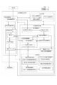
- FIG. 2 is a block diagram schematically showing each configuration of the present embodiment. The configuration of the biological information measuring device 1 will be described with reference to FIG.
- the biological information measuring device 1 is a Western-style toilet part 4 provided with a toilet bowl function part 9 and a sanitary washing function part 91 as in a normal toilet, and biological information for measuring biological information such as the state of excreted urine.
- the measurement unit 5 includes a remote control unit 70 that performs various operations on the Western-style toilet 4 and the biological information measurement unit 5 and an input / output unit 7 that includes a print output unit 73 that outputs measurement results.
- the western-style toilet part 4 incorporates a water supply control means 21 for controlling the supply of water used for cleaning and measurement from the outside.
- the city water 20 to be supplied is branched by the water supply control means 21 to the toilet bowl function unit 9, the sanitary washing function unit 91, and the biological information measurement unit 5 through the water supply pipes, and supplied. That is, the water supplied to the Western-style toilet unit 4 is supplied to the toilet function unit 9 for toilet cleaning, is supplied to the sanitary cleaning function unit 91 for sanitary cleaning, and is further measured by the biological information measuring unit 5 For use, it is divided and supplied to pipes connected to each.
- the Western-style toilet 4 is provided with a bowl 22 that receives excrement excreted by the user as with a normal toilet, and a trap 24 that communicates the interior of the bowl 22 with a drainage socket 25 through a drainage socket 25. ing.
- a reservoir 23 is formed to prevent bad odors and sanitary pests generated in the drain pipe 26 from entering the toilet.
- the accumulated water mixed with excrement excreted by the user is discharged to the drain pipe 26 outside the apparatus via the drain socket 25.
- the remote controller 70 (remote controllers 71 and 72) is provided with various operation switches for operating the biological information measuring apparatus 1. Each operation of the remote control operation unit 70 is transmitted as an operation signal to the Western-style toilet unit 4 and the biological information measurement unit 5 that are operated by a microcomputer. The frequency and time interval defined in the present application are set and input by the refresh operation setting input unit 74 of the remote control operation unit 70.
- the biological information measurement unit 5 includes a water pressure measurement mechanism unit 51, a measurement start water level formation mechanism unit, a calibration water level formation mechanism unit 82, a calibration water level formation mechanism unit 81, a water replenishment mechanism unit 75, a pipe switching mechanism unit 52, and the like. And a control processing unit 60 are provided.
- the water pressure measuring mechanism 51 measures the pressure (water head pressure) generated by the water level of the stored water 23 through a measurement pipe line that communicates with the stored water 23.
- the measurement start water level formation mechanism forms a water level at the start of measurement.
- the calibration water level formation mechanism unit 82 forms a calibration water level necessary for calibrating the output of the water pressure measurement mechanism unit 51.
- the calibration water level formation mechanism unit 81 creates a calibration water level necessary for creating a water level-water quantity calibration curve based on the relationship between the water level and the water level depending on the shape of the bowl 22.
- the water replenishment mechanism unit 75 supplies water for forming the calibration water level and the measurement start water level described above.
- the pipe switching mechanism unit 52 includes a plurality of switching valves for forming a water flow path necessary for each operation.
- the control processing unit 60 performs various processes such as control of various operations and storage / calculation performed by the entire biological information measurement unit 5 including these mechanisms.
- the stored water level calculation unit 50 that obtains the water level of the stored water 23 that changes due to urination of the subject from the pressure information measured by the water pressure measurement mechanism unit 51 and the stored water level calculation unit 50 are used.
- a stored water amount calculation unit 90 that calculates the amount of stored water in the bowl 22 from the stored water level, and a living body that calculates biological information such as urine volume excreted by the subject, urine specific gravity, and other biological information from the stored water amount information obtained by the stored water amount calculation unit 90
- a calibration water level formation support unit 80 that instructs the operation of the information calculation unit 30, the calibration water level formation mechanism unit 81, and a refresh operation instruction unit 95 that controls a later-described refresh operation for regenerating the calibration water level are provided.
- the stored water level calculation unit 50 measures the pressure (water head pressure) generated by the water level of the stored water 23 using the water pressure measurement mechanism unit 51 via the measurement pipe line communicating with the stored water 23, and the obtained measurement value ( By applying an output-pressure calibration curve representing the relationship between the sensor output and the pressure (water head pressure) obtained in advance to the output), the pressure generated by the water level of the accumulated water 23, that is, the reservoir under atmospheric pressure. Find the water level.
- the sensor output changes due to the aforementioned drift phenomenon.
- a water pressure sensor output calibration unit 59 included in the output calibration means of the embodiment is incorporated in the stored water level calculation unit 50 in order to calibrate the measurement value every time the stored water level is measured.
- the calibration water level formation instructing unit 80 instructs the calibration water level formation mechanism unit 81 to create a calibration water level for creating the relationship between the water level and the water level in the bowl 22 of the Western-style toilet 4 to be used.
- This creation operation is executed and stored when the apparatus is installed. In the procedure, the water pressure due to the water level when the predetermined amount of water is sucked from the bowl 22 by the calibration pump 811 is measured by the water pressure measuring mechanism 51, and the relationship between the water pressure and the water amount is recorded.
- the relationship between the accumulated water pressure and the accumulated water amount in the predetermined water level range of the bowl 22 is learned and stored in the water level-water amount calibration curve storage unit 58.
- the stored water level formed in the bowl 22 is also influenced by the floor inclination of the installation site, the internal pressure of the drainage pipe, and the like. Therefore, the water level-water calibration curve must be created and stored at the time of installation when performing high-accuracy measurement, and it is also rewritten during regular verification.
- the water pressure measurement mechanism unit 51 is included in the pressure measurement unit in the embodiment
- the stored water level calculation unit 50 is included in the stored water level calculation unit in the embodiment
- the calibration water level formation mechanism unit 82 is in the embodiment.
- the water pressure sensor output calibration unit 59 is included in the output calibration means in the embodiment.
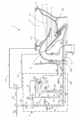
- FIG. 3 is a system configuration diagram schematically showing the overall configuration of the embodiment according to the present invention, and shows a specific configuration of the urination information measuring apparatus 1 according to the present embodiment.
- detailed configurations of the sanitary washing device 91 and the toilet bowl function unit 9 are omitted for convenience of explanation.
- the toilet 4 is connected to a drain pipe 26 via a drain socket 25.
- a reservoir 23 having a sealing function for blocking communication with the drainage pipe 26 by the trap 24 is formed.
- Water supply from an external water supply source such as a water supply is performed by a stop cock 210, a branch fitting 211, and a three-way valve 213 included in the water supply control means 21 and a rim water supply pipe 214 directed to the rim water spout 215 and an implementation described later.
- Water supply to the replenishing tank 61 is performed by the on-off valve 611, and a predetermined amount is detected by the float switch 612, and water supply is stopped.
- the overflow pipe 64 discharges to the drain pipe 26 via the drain pipe connecting pipe 562 via the trap tank 551 on the way, causing water leakage to the outside of the apparatus. Considered not to.
- a branching device 542 is provided in the middle of the jet water supply pipe 216, and a pipe 543 that communicates with the pressure sensor 512 and corresponds to the measurement pipe of the embodiment is provided. It is connected.
- a branching tool 545 is provided in the middle of the pipe line 543, and a supplementary water pipe 63 communicating with the supplementary water tank 61 is branched and connected.
- An on-off valve 522 for opening and closing the water refilling pipe 63 is provided in the middle.
- a branching tool 546 is further provided in the middle of the pipe 543, and an opening / closing valve 525 for opening and closing the pipe and a calibration pump 811 for sucking the accumulated water 23 are provided in the middle, and communicates with the trap tank 551.
- a pipeline 812 is connected.
- the trap tank 551 is a drain tank that performs a trap function for the drain pipe in order to discharge surplus water such as overflow water generated by the operation of each part to the drain pipe 26.
- the pipe line 543 is connected to a pressure sensor 512 included in the pressure measuring means in the embodiment, and further, a water level forming pipe 511 included in the water column forming means in the embodiment is connected to the pressure sensor 512.
- the water level forming pipe 511 is provided with an opening that is extended into the trap tank 551 and opened to the atmosphere, and is a vertical pipe portion having an atmosphere open end 511a at a predetermined height in the vertical direction in the embodiment.
- a U-shaped pipe line system having both ends opened together with the bowl 22 communicated with the measurement pipe line is formed.
- the water level forming pipe 511 in the present embodiment fluidically attenuates the vibration component transmitted in the measurement pipe line due to the undulation of the water surface of the accumulated water 23 due to urination, and the pressure sensor 512 makes the water pressure of the accumulated water 23 more accurate. Therefore, it is configured to be formed of a narrow tube having a predetermined inner diameter.
- the water level forming pipe 511 also has a function of an output calibration pipe for calibrating the output of the pressure sensor 512.
- the stored water level during measurement standby is the measurement start water level Y
- the stored water level 23 is set to the measurement start water level Y by using the toilet flushing function of the toilet function unit 9.
- the ball 22 is washed by water discharged from the pipe line 214, and then all the accumulated water 23 is drained by a siphon phenomenon induced by the jet water discharged from the jet water outlet 541 by water supply from the pipe line 216. It is discharged to the pipe 26. Thereafter, the water 23 is supplied by the water discharged from the rim water spouting port 215 until the water level X is exceeded.
- the on-off valve 524 and the on-off valve 525 are closed, the on-off valve 521 and the on-off valve 522 are opened, and the replenishing water tank 61 and the accumulated water 23 are communicated with each other through the water refilling pipe 63 and the pipe 543.
- the water supply pump 62 is operated at a predetermined water supply rate for a predetermined time, and the water stored in the water replenishment tank 61 is discharged from the jet water outlet 541, whereby the stored water level is changed to the breaking water level X of the trap 24.
- the operation of setting the measurement start water level Y higher by a predetermined amount is performed.
- the open / close valves 521 and 525 are closed and the open / close valves 522 and 524 are opened.
- the water supply pump 62 is operated to guide the water stored in the water supply storage tank 61 to the water level forming pipe 511, and overflow from the atmosphere open end 511a into the trap tank 551 to enter the water level forming pipe 511. Is filled with water, a water column having a fixed length to the open end of the water level forming pipe 511 is created.
- the reason for waiting in the water level forming tube 511 to be full is to take into account that the subject patient includes a disease that the patient cannot withstand urination.
- the water level forming pipe 511 is filled with the water state in advance and waits. However, consideration is given so that the measurement operation can be immediately shifted to.
- the pressure head 512 measures the water head pressure of the water column of a certain height set by the water level formation pipe 511 immediately before the measurement in accordance with the measurement start operation of the subject. By doing so, the output calibration of the relationship between the output value of the pressure sensor 512 and the water level is performed in consideration of environmental variation factors such as atmospheric pressure and temperature at the time of calibration, and corresponding to the reference water level value.
- the opening end surface of the water level forming pipe 511 is not facing upward but is facing sideways. This is because when the pipeline is opened and closed upward, the water surface becomes convex upward or concave due to surface tension in a gravitational environment, making it impossible to create a stable absolute water level. .
- the water level forming pipe 511 In order to reduce the amount of error, there is a method of reducing the cross-sectional area of the water level forming pipe 511, but the water level forming pipe 511 also has a function of releasing the pressure wave generated in the pipe 543 to be guided, and is necessary. The pipe cannot be made thinner than that.
- the water level forming pipe 511 has a function of releasing the pressure wave and a function of calibrating the absolute value.
- the on-off valves 521 and 524 are opened to connect the accumulated water 23 and the pipe 543 of the water level forming pipe 511 so that the measurement start water level Y and the water level in the water level forming pipe 511 are at the same height.
- the change in the water level is measured by the pressure sensor 512.
- the trap tank 551 has a drainage pipe connecting line 562 extending from a position where a sealed water is formed inside to drain the overflow water from the water level forming pipe 511 at the time of output calibration to the drainage pipe 26.
- a drainage pipe connection port 563 provided in the drainage socket 25 is connected. Thereby, it functions as an edge cutting means that seals the connection pipe line with the drain pipe by water sealing.
- the urination information measuring device 1 of the present embodiment has a function of measuring the correspondence between the water level of the stored water 23 and the amount of stored water at the installation site and storing it as a calibration relationship in the embodiment.
- a calibration pump 811 that is a fixed-aspiration pump capable of sucking an arbitrary amount is provided.
- the calibration pump 811 sucks the accumulated water 23 using the pipe line 543 which is the measurement pipe line in the embodiment, and can discharge it toward the drain pipe via the trap tank 551 and the drain pipe connecting pipe line 562.
- the accumulated water 23 is sucked and discharged from the bowl 22 by a predetermined amount by the calibration pump 811.
- the water head pressure generated by the stored water level is measured by the pressure sensor 512 to calculate the water level. By doing so, the calibration relationship between the stored water level and the stored water amount is acquired.
- the calibration curve storage unit 31 may store the calibration curve for each device. For example, this configuration can be applied to a toilet bowl in which at least the bowl portion is made of resin.
- the occurrence of an error in the water level measurement value in the apparatus configuration to which the embodiment is applied is caused by the formation of bubbles of dissolved air from the water inside the water level forming pipe 511, which is caused by being left unused for a long period of time. It is.
- the output of the pressure sensor 512 is calibrated by the water level forming pipe 511 that is full of water every time measurement is performed. However, if the measurement interval is extended for a long time or the environmental temperature rises, bubbles may be generated from the water in the measurement tube 512 and collected at the top of the measurement tube 512.
- the generated bubbles accumulate at the top of the water level forming pipe 511 and grow into large bubbles, which are then filled to the full level. Lower the internal water column by the bubble diameter. As a result, the calibration output of the pressure sensor 512 is lowered.
- the bubbles generated in the conduit 543 for guiding pressure may inhibit the pressure transmission and prevent the pressure from being correctly transmitted, or may cause a pulsation in the pressure fluctuation over time. Further, when the bubbles are caught by the connecting portion of the pressure sensor 512, a damper is formed with respect to the transmitted pressure, and in this case, the output of the pressure sensor is lowered.
- the open / close valve 522 and the open / close valve 524 are opened to supply the water in the replenishing tank 61 to the accumulated water pressure level forming pipe 511, and the bubbles appearing inside the water level forming pipe 511 are pushed out and discharged by being left for a long time.
- the refresh operation is performed. Since the electrical output of the pressure sensor 512 is affected by the temperature change in the environment, a state in which the water temperature in the measurement tube greatly fluctuates must be avoided when performing this operation. For this reason, in this embodiment, the water that is considered to have substantially the same temperature as the water in the measuring tube is used to pass water for 1 second to 2 seconds using the stored water in the water retention tank 61 inside the biological information measuring unit 5.
- the water level forming pipe 511 is moved. Bubbles in the water level forming pipe 511 closest to the pressure sensor 512 are sequentially pushed out into the trap tank 551 and disappear in the course of this operation, so that the water level forming pipe 511 is filled with only water up to the upper atmospheric open end. It becomes a water column in the state and an accurate calibration water level as designed is obtained.
- the air opening end 511a of the water level forming pipe 511 is not in a simple form opened upward, but is located in the trap tank 551.
- output calibration in the embodiment uses what is called water head pressure, this state does not affect calibration accuracy.
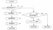
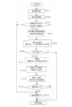
- FIG. 4 is a flowchart showing a flow of operation of the example according to the embodiment.
- the presence / absence of a measurement start operation is monitored. That is, the presence / absence of a measurement start operation is determined in S11, and if there is a measurement start operation, the biological information measurement operation starting from S12 is started.
- the biological information measurement operation is divided into a pre-measurement operation in S12, a urination information measurement in S13, and a post-measurement operation in S14. Details of the pre-measurement operation and the post-measurement operation related to the embodiment will be described later.
- the process proceeds to S21, and it is confirmed whether or not the conditions for performing the set refresh operation are met. If it matches, a refresh operation is performed in S22. The specific operation of the refresh operation will be described in detail later. If not, the process returns to the beginning, and it is determined again whether or not the measurement start operation of S11 is performed.
- the biological information measurement operation may be read as an operation for other purposes.
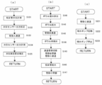
- FIG. 5 shows detailed steps of each operation described in FIG.
- FIG. 5A is an operation flow related to the pre-measurement operation in S12.
- the output voltage of the pressure sensor 512 is measured as a calibration water level measurement.
- the water level in the water level forming pipe 511 is the full water level up to the atmosphere open end 511a formed in the post-measurement operation performed at the previous measurement, and the calibration water level of the predetermined water level in the embodiment. It has become.
- S122 is a step of performing water level sensor output calibration, and an output calibration operation for comparing the output voltage of the pressure sensor 512 with the full water level of the water level forming pipe 511 is performed.
- the on-off valve 521 and the on-off valve 524 existing in the pipe A are opened in S123, the pipe line between the ball 22 and the water level forming pipe 511 is communicated, and the ball 22 and the water level forming pipe 511 are connected. Make the water level the same. In this state, the water level forming pipe 511 functions as a part of the water level measuring means in the water level measuring device for the stored water.
- S124 the output voltage of the pressure sensor 512 is measured as the water level sensor output measurement.
- S125 is a step of confirming the measurement start water level before urination, and from which water level position the urine information is measured in a pre-stored water level-water quantity calibration curve indicating the calibration relationship between the stored water level and the accumulated water level. Perform processing such as origin correction.
- FIG. 5B is an operation flow related to the post-measurement operation in S14. After the series of urination information measurement operations in S13 is completed, the ball 22 is washed in S141 by the user's toilet cleaning operation, and then the water stored in the balls 22 is siphoned by the water discharged from the jet outlet 511. 23 is discharged toward the drain pipe 26.
- S142 is an operation step similar to a series of operations of toilet flushing for recondensing the trap 24 in a broken state in order to seal the trap 24 again.
- S143 is a step in which the on-off valve 521 and the on-off valve 522 are opened to form the pipe line B between the replenishing tank 61 and the ball 22 in order to form the measurement start water level Y used for the next measurement.
- the water replenishment pump 62 is driven to supply water in the water tank 61, and the water level of the stored water 23 is replenished until it reaches a predetermined measurement start water level Y.
- the open / close valve 521 is closed in S145 in order to set the water level of the water level forming pipe 511 to the calibration water level that is the water level for calibrating the output of the pressure sensor 512.
- the open / close valve 524 is opened to switch the pipe line communicating with the pipe line C.
- the water replenishing pump 62 is driven to supply a predetermined amount of water to the water level forming pipe 511, whereby the water level forming pipe 511 becomes full and excess water is discharged to the trap tank 551.
- S147 is a step in which the water replenishment pump 62 is closed, the on-off valve 524 is closed, and the pipeline C is closed. In this state, the water level forming pipe 511 is maintained in a full water state, and functions as a calibration pipeline in the embodiment.
- FIG. 5C is an operation flow relating to the refresh operation in S22.
- step S221 the on / off valve 521 and the on / off valve 524 are opened to form the pipe C in order to drain the water stored in the replenishing tank 61 through the water level forming pipe 511.
- step S222 the water replenishing pump 62 is operated for a predetermined time to supply a predetermined amount of water in the water replenishing tank 61 toward the water level forming pipe 511.
- the water replenishment pump 62 is stopped in S223.
- water is filled up to the upper end of the water level forming pipe 511, and a calibration water level having a predetermined height is re-formed.
- the water replenishing pump 62 may not be operated, and the water may flow only by the head pressure of the water replenishing tank 61.
- the predetermined timing for performing the refresh operation in the embodiment which is the refresh operation condition described above may be changed according to the medical condition. For example, when it is not used at night as in a doctor's office and is frequently used only in the daytime, it is recommended to perform a refresh operation at a predetermined time in the embodiment, that is, for example, at 6:00 am before medical examination time. The Further, if the medical institution has a low use frequency and a long use interval, the refresh operation is performed at a predetermined time interval in the embodiment. However, the refresh operation itself is not necessary when it is expected to be used 24 hours a day, such as when used in an inpatient ward of a large hospital. You may make it provide the selection means which can select embodiment of operation
- FIG. 6 is a flowchart showing the flow of operation of another example according to the embodiment.
- S31 is a step in which the subject inputs an instruction to start biological information measurement such as urine flow rate.
- S32 is a step of measuring the position of the measurement start water level, which is the water level in the bowl when starting the measurement.
- S33 is a step of confirming whether or not the measured measurement water level has changed by a predetermined value or more from a pre-formed water level, and confirms whether or not a water level change due to mischief or cleaning has occurred. If there is no deviation greater than the predetermined value, it means that normal measurement is possible, and the routine branches to step 50 to start normal measurement operation.
- step 34 When the deviation of a predetermined value or more is confirmed, at step 34, it is informed that an abnormality has occurred and guides the subsequent operation selection. Specifically, whether to stop the measurement or reset the measurement start water level is displayed, and the subject selects an operation in step S35. In this case, on the assumption that the measurement accuracy is lowered, there is an option to force the measurement without resetting the water level. Considering that excretion may not be possible, in this case, the process proceeds to step S50.
- Step S36 is a step of determining whether or not water level resetting has been selected. When water level resetting is selected, toilet flushing is performed, and then a resetting operation for creating a measurement start water level is executed in step S37. In step S36, when the water level resetting is not selected, it is considered that the measurement stop is selected, and the measurement sequence is ended. When the resetting is completed, the resetting is completed and measurement preparation is completed in step S38, and a guide for waiting for a measurement start instruction is issued.
- Step S39 is a step of performing an operation instruction operation. When the start of measurement is determined in step S40, a normal measurement operation is performed in step S50.
- step S51 the measurement sequence is terminated in step S51.
- this algorithm confirms the deviation of the measurement start water level with the measurement operation as a trigger.
- the trigger may be set at a time interval, for example, every 10 minutes, and the measurement start water level may be continuously checked. If there is a measurement start operation by the subject during that time, the measurement action is performed by interrupting the flowchart.
- a remote control operation unit 70 may be provided with a changeover switch for selecting either measurement stop or resetting of the measurement start water level.
- a maintenance information display unit may be provided in the remote control operation unit to notify the necessity of maintenance of the apparatus itself when the cleaning water supply means 21 fails and water cannot be stopped properly.
- the present embodiment described above is a water level measuring device incorporated in a biological information measuring device.
- the embodiment is a water level measuring device having a function of calibrating the pressure of the pressure measuring means, with the measurement target being the water level of the toilet bowl. Applies to
- the embodiment even if the operation of the water level measuring device is stopped for a long time or the environmental temperature of the installation location is changed, it is possible to maintain the same measurement accuracy as when performing measurement constantly. The effect that it can be obtained. Furthermore, when an abnormality occurs in the measurement environment, an appropriate countermeasure can be taken by notifying the outside of the abnormality.
- Zet water supply pipe 511 Water level forming pipe 511a ... Atmospheric open end (water level forming pipe) DESCRIPTION OF SYMBOLS 512 ... Pressure sensor 521 ... Open / close valve 522 ... Open / close valve 524 ... Open / close valve 525 ... Open / close valve 541 ... Zette water outlet (measurement communication port) 543 ... Pipe line 551 ... Trap tank 561 ... Drain pipe pressure measuring sensor 562 ... Drain pipe connection pipe 563 ... Drain pipe connection port 611 ... On-off valve 612 ... Float switch 811: Calibration pump 812: Calibration pipeline X ... Broken water level Y ... Measurement start water level Z ... Post urine water level H ... Overflow water level
Landscapes
- Physics & Mathematics (AREA)
- Fluid Mechanics (AREA)
- General Physics & Mathematics (AREA)
- Bidet-Like Cleaning Device And Other Flush Toilet Accessories (AREA)
- Sanitary Device For Flush Toilet (AREA)
- Measurement Of Levels Of Liquids Or Fluent Solid Materials (AREA)
Applications Claiming Priority (4)
| Application Number | Priority Date | Filing Date | Title |
|---|---|---|---|
| JP2011101721 | 2011-04-28 | ||
| JP2011-101721 | 2011-04-28 | ||
| JP2012010993A JP5915966B2 (ja) | 2011-04-28 | 2012-01-23 | 水位測定装置 |
| JP2012-010993 | 2012-01-23 |
Publications (1)
| Publication Number | Publication Date |
|---|---|
| WO2012147413A1 true WO2012147413A1 (ja) | 2012-11-01 |
Family
ID=47071941
Family Applications (1)
| Application Number | Title | Priority Date | Filing Date |
|---|---|---|---|
| PCT/JP2012/055721 Ceased WO2012147413A1 (ja) | 2011-04-28 | 2012-03-06 | 水位測定装置 |
Country Status (2)
| Country | Link |
|---|---|
| JP (1) | JP5915966B2 (enExample) |
| WO (1) | WO2012147413A1 (enExample) |
Cited By (1)
| Publication number | Priority date | Publication date | Assignee | Title |
|---|---|---|---|---|
| CN106918378A (zh) * | 2017-03-14 | 2017-07-04 | 嘉兴学院 | 水位传感器自动检测系统 |
Families Citing this family (4)
| Publication number | Priority date | Publication date | Assignee | Title |
|---|---|---|---|---|
| JP2014145624A (ja) * | 2013-01-28 | 2014-08-14 | Toto Ltd | 排泄物量測定装置 |
| JP6839409B2 (ja) * | 2016-10-12 | 2021-03-10 | Toto株式会社 | 生体情報測定装置 |
| JP7181505B2 (ja) * | 2019-01-23 | 2022-12-01 | Toto株式会社 | 水洗大便器 |
| JP7379950B2 (ja) * | 2019-08-30 | 2023-11-15 | Toto株式会社 | 生体情報測定装置 |
Citations (2)
| Publication number | Priority date | Publication date | Assignee | Title |
|---|---|---|---|---|
| JP2002021148A (ja) * | 2000-07-04 | 2002-01-23 | Toto Ltd | トイレ管理装置 |
| JP2007077755A (ja) * | 2005-09-16 | 2007-03-29 | Toto Ltd | 排尿情報測定便器 |
Family Cites Families (3)
| Publication number | Priority date | Publication date | Assignee | Title |
|---|---|---|---|---|
| JPH11133024A (ja) * | 1997-08-28 | 1999-05-21 | Toto Ltd | 尿検査装置 |
| JP2004027530A (ja) * | 2002-06-24 | 2004-01-29 | Toto Ltd | 便器装置 |
| JP2006098222A (ja) * | 2004-09-29 | 2006-04-13 | Toto Ltd | 生体情報測定装置 |
-
2012
- 2012-01-23 JP JP2012010993A patent/JP5915966B2/ja active Active
- 2012-03-06 WO PCT/JP2012/055721 patent/WO2012147413A1/ja not_active Ceased
Patent Citations (2)
| Publication number | Priority date | Publication date | Assignee | Title |
|---|---|---|---|---|
| JP2002021148A (ja) * | 2000-07-04 | 2002-01-23 | Toto Ltd | トイレ管理装置 |
| JP2007077755A (ja) * | 2005-09-16 | 2007-03-29 | Toto Ltd | 排尿情報測定便器 |
Cited By (1)
| Publication number | Priority date | Publication date | Assignee | Title |
|---|---|---|---|---|
| CN106918378A (zh) * | 2017-03-14 | 2017-07-04 | 嘉兴学院 | 水位传感器自动检测系统 |
Also Published As
| Publication number | Publication date |
|---|---|
| JP2012237187A (ja) | 2012-12-06 |
| JP5915966B2 (ja) | 2016-05-11 |
Similar Documents
| Publication | Publication Date | Title |
|---|---|---|
| JP5915966B2 (ja) | 水位測定装置 | |
| US9464420B2 (en) | Leak detection on flush valve | |
| ES2857507T3 (es) | Unidad sanitaria con dispositivo de monitorización | |
| US20120085781A1 (en) | Liquid Delivery System, Liquid-Delivery Switching Device, and Liquid-Flowpath Regulating Device | |
| JP5435402B2 (ja) | 排尿情報測定装置 | |
| JP7740823B2 (ja) | 流量計校正システム、基板処理装置および流量計校正方法 | |
| AU2015295219A1 (en) | Device for toilets | |
| JP2008154625A (ja) | 内視鏡洗浄消毒装置、及び内視鏡洗浄消毒装置の薬剤供給制御方法 | |
| CN101784730A (zh) | 双冲洗阀回注 | |
| JP2009084821A (ja) | 排尿情報測定装置 | |
| JP4941879B2 (ja) | 水洗便器 | |
| JP2007077755A (ja) | 排尿情報測定便器 | |
| JP5990942B2 (ja) | 生体情報測定装置 | |
| JP2014145624A (ja) | 排泄物量測定装置 | |
| JP6213895B2 (ja) | 水洗大便器 | |
| JP2007327307A (ja) | 生体情報測定便器 | |
| JP4524799B2 (ja) | 尿量測定大便器 | |
| JP2010236211A (ja) | タンク装置 | |
| JP6241343B2 (ja) | 水洗大便器 | |
| JP2025010705A (ja) | 大便器ユニット、および、生体情報測定装置 | |
| JP2015113674A (ja) | 水洗大便器 | |
| JP2008008133A (ja) | 排尿情報測定装置 | |
| JP2008175000A (ja) | 排尿情報測定装置 | |
| JP4941888B2 (ja) | 生体情報測定便器 | |
| US20120227172A1 (en) | Water saver toilet control valves and methods |
Legal Events
| Date | Code | Title | Description |
|---|---|---|---|
| 121 | Ep: the epo has been informed by wipo that ep was designated in this application |
Ref document number: 12777121 Country of ref document: EP Kind code of ref document: A1 |
|
| NENP | Non-entry into the national phase |
Ref country code: DE |
|
| 122 | Ep: pct application non-entry in european phase |
Ref document number: 12777121 Country of ref document: EP Kind code of ref document: A1 |