WO2012147413A1 - 水位測定装置 - Google Patents
水位測定装置 Download PDFInfo
- Publication number
- WO2012147413A1 WO2012147413A1 PCT/JP2012/055721 JP2012055721W WO2012147413A1 WO 2012147413 A1 WO2012147413 A1 WO 2012147413A1 JP 2012055721 W JP2012055721 W JP 2012055721W WO 2012147413 A1 WO2012147413 A1 WO 2012147413A1
- Authority
- WO
- WIPO (PCT)
- Prior art keywords
- water level
- water
- measurement
- calibration
- pressure
- Prior art date
Links
Images

Classifications
-
- G—PHYSICS
- G01—MEASURING; TESTING
- G01F—MEASURING VOLUME, VOLUME FLOW, MASS FLOW OR LIQUID LEVEL; METERING BY VOLUME
- G01F23/00—Indicating or measuring liquid level or level of fluent solid material, e.g. indicating in terms of volume or indicating by means of an alarm
- G01F23/14—Indicating or measuring liquid level or level of fluent solid material, e.g. indicating in terms of volume or indicating by means of an alarm by measurement of pressure
- G01F23/18—Indicating, recording or alarm devices actuated electrically
-
- G—PHYSICS
- G01—MEASURING; TESTING
- G01F—MEASURING VOLUME, VOLUME FLOW, MASS FLOW OR LIQUID LEVEL; METERING BY VOLUME
- G01F25/00—Testing or calibration of apparatus for measuring volume, volume flow or liquid level or for metering by volume
- G01F25/20—Testing or calibration of apparatus for measuring volume, volume flow or liquid level or for metering by volume of apparatus for measuring liquid level
-
- E—FIXED CONSTRUCTIONS
- E03—WATER SUPPLY; SEWERAGE
- E03D—WATER-CLOSETS OR URINALS WITH FLUSHING DEVICES; FLUSHING VALVES THEREFOR
- E03D5/00—Special constructions of flushing devices, e.g. closed flushing system
- E03D5/10—Special constructions of flushing devices, e.g. closed flushing system operated electrically, e.g. by a photo-cell; also combined with devices for opening or closing shutters in the bowl outlet and/or with devices for raising/or lowering seat and cover and/or for swiveling the bowl
Definitions
- Embodiments of the present invention relate to measuring the water level in a bowl of a Western-style toilet, and more particularly to a water level measuring apparatus suitable for measuring the water level with high accuracy and stability.
- the level of accumulated water is measured during excretion into the bowl of a Western-style toilet, and the calibration is the relationship between the accumulated water level and the amount of accumulated water obtained in advance.
- a urination information measuring device that measures the amount of urine excreted and the urine flow rate, which is the amount of urine per unit time, by determining the amount of change in accumulated water using a line (see, for example, Patent Document 1).
- Measure the water level in the bowl in this device does not directly measure the water pressure generated by the water. Instead, the water pressure (water head pressure) generated by the water column formed in the measuring tube when the standing tubular measuring tube provided outside the bowl is connected to the stored water in the bowl is the pressure that is connected to the measuring tube. It is converted into electrical output using a sensor and measured.
- a pressure transmission medium for transmitting the pressure of the measurement target to the pressure sensor is required in the measurement pipeline.
- a gas such as air
- the compressibility affects the measurement accuracy in terms of responsiveness. Therefore, liquid is often used as a pressure transmission medium.
- the observation side (pressure sensor side) of the measurement pipeline is a closed end, it is difficult to remove air remaining in the measurement pipeline when the apparatus is assembled. For this reason, like the device described in Patent Document 1, the pressure sensor side is often a U-shaped pipe line having an open air end that can be easily vented even after the device is assembled.
- the apparatus described in Patent Document 1 is configured such that the pressure transmission medium is water handled by the apparatus itself, so that air can be vented without problems even at the site when the apparatus is installed.
- this device supplies water to the pressure sensor side in a state where communication on the water storage side of the measurement pipe is interrupted, and overflows from the open end of the atmosphere, so that residual air in the measurement pipe is combined with water.
- the structure which fills the inside of a measurement pipe line only with a pressure transmission medium is employ
- the treatment of water, which is a pressure transmission medium discharged during this operation, can be easily carried out by transporting it out of the system through a drain line that the apparatus originally has.
- the water level (water head pressure) generated by the water level is obtained by measuring the water level required for calculating the amount of water stored in the bowl of the toilet bowl.
- the horizontal cross-sectional area of the surface of the stored water at the time of measurement is considerably larger than the change range of the amount of stored water to be measured, the amount of change in water pressure to be observed becomes small. Therefore, a highly accurate pressure measuring system used in such a form is required.
- the pressure sensor generally used in the pressure measurement system has a temperature compensation function to prevent the output state from changing depending on the ambient temperature during use.
- a water level measuring apparatus having such a configuration, it cannot be completely compensated because it is affected not only by the temperature of the atmosphere but also by the temperature of the water that is the pressure transmission medium in direct contact therewith.
- a drift phenomenon occurs in which the pressure-output relationship of the pressure sensor changes while being minute. Therefore, if the water level value is calculated based on the pressure-output calibration curve obtained in advance for the pressure-output relationship of the pressure sensor, the actual water level will differ to a negligible level.
- the apparatus described in Patent Document 1 described above is provided with a configuration for calibrating the pressure sensor output that is generally performed when performing high-accuracy measurement.
- the open end of the measuring tube is formed at a predetermined position higher than the stored water level fluctuation range to be measured.
- a water supply means that can supply an arbitrary amount of water to this measuring pipe, supply water in a state where communication with the reservoir side is cut off, fill the standing pipe full, and open from the sensor communication position to the open end.
- a water column of a certain height up to is formed.
- the structure which calibrates the output of a sensor by setting the sensor output when measuring the water level of the water column of this fixed height as the water level for calibration as a reference value is adopted.
- the calibration water level is formed for the next calibration after the measurement is completed. Each time the original water level is measured, the pre-measurement preparatory operation is performed immediately before the start of measurement to prevent the occurrence of measurement errors by measuring the sensor output value of the calibration water level and calibrating the sensor output. ing.
- the water level changes if the apparatus is not used for a long time with the calibration water level formed. Then, as a result of performing calibration while the calibration water level serving as the calibration reference water level is changed, it has been found in the confirmation test of the present inventor that there is a problem that an error occurs in the measurement result of the stored water level.
- the cause of this change in the calibration water level is that the air dissolved in the water in the measurement tube described above gradually emerges as bubbles as the standby time elapses, and bubbles are gathered near the open end of the atmosphere at the upper end of the measurement tube. It was confirmed that the water level in the pipe was lowered by pushing out the water in the pipe to the outside. Furthermore, the buffering effect on the evaporation of water in the pipe from the open end of the atmosphere and the pressure transmission by the bubbles present in the water was considered as a possibility.
- the measurement start water level that is the stored water level when starting the measurement that was formed in advance becomes high during standby, As a result, it was also found that the maximum measurable range from the measurement start water level to the overflow water level was reduced.
- the cause of this phenomenon could be, for example, when water was added to the bowl with mischief or when the water supply valve of the toilet itself leaked due to poor water stoppage.
- the present invention has been made to solve the above problems, and an object of the present invention relates to maintenance of measurement accuracy of a water level measuring apparatus using pressure measuring means for water stored in a toilet bowl. .
- the invention described in claim 1 includes a toilet having a bowl for storing stored water and receiving user's excrement, a vertical tubular water level forming pipe having an upper end as an open air end, A pressure measuring means for measuring a pressure generated by the water level in the water level forming pipe, a lower end portion of the water level forming pipe and the stored water in the bowl are communicated, and the water level of the stored water is the same as the water level in the measuring water level forming pipe.
- a measuring water level forming means for forming a measuring water level; a stored water level calculating means for calculating the water level of the stored water based on a pressure measurement value measured by the pressure measuring means at the measuring water level; and water supply to the water level forming pipe
- Calibration water level forming means for forming a calibration water level of a predetermined height in the water level forming pipe, output calibration means for calibrating the output of the pressure measuring means based on the output value of the pressure measuring means at the calibration water level
- the water level measuring device further comprises: a refresh operation control means for causing the calibration water level forming means to perform a refresh operation for re-forming the calibration water level at a predetermined timing. Since the reference calibration water level is updated and always kept within the allowable range in the output calibration operation, the pressure measurement means output calibration can be performed accurately, so that the inside of the toilet bowl The measurement accuracy of the stored water level is not reduced.
- the invention according to claim 2 is characterized in that the refresh operation causes the water in the water level forming pipe to overflow from the atmosphere open end by replenishing water to the water level forming pipe. Since it is physically limited to the tip position of the vertical pipe, the upper limit of the water supply amount in the external water supply operation at the time of reforming is eliminated, and the water supply amount can be controlled with a simple configuration.
- the invention according to claim 3 further includes a replenishing tank for storing water, wherein the replenishing is performed by the stored water in the replenishing tank, so that at least the time other than when the apparatus is in operation Since water with a small amount of dissolved air staying is used, the generation of bubbles until the subsequent measurement is reduced, and the occurrence of a phenomenon of a decrease in the calibration water level can be suppressed.
- the invention according to claim 4 is characterized in that the predetermined timing is a predetermined time, so that the measurement state can be in a good state before medical treatment of a medical institution, There is no need to worry about a decrease in measurement accuracy.
- the invention according to claim 5 is characterized in that the predetermined timing is a predetermined time interval, so that there is a concern about a decrease in accuracy without being influenced by a medical institution's examination time or medical condition. There is nothing to do.
- a toilet comprising a bowl for storing stored water and receiving a user's excrement, and a vertical tube having a lower end communicating with the stored water in the bowl and having an upper end as an air release end.
- the water level forming pipe, the pressure measuring means for measuring the pressure generated by the water level in the water level forming pipe, and the water level for calculating the water level based on the pressure measurement value measured by the water pressure measuring pressure measuring means An output calibration for calibrating the output of the pressure measuring means based on the output value of the calculating means, the calibration water level forming means for forming a calibration water level of a predetermined height in the water level forming pipe, and the pressure measuring means at the calibration water level And a water level measurement device having a means for receiving an accumulated water level measurement start signal, and when the accumulated water level determined by the accumulated water level calculation means deviates from a predetermined level by a predetermined value or more.
- an abnormality informing means for informing by the measuring range to know the status is not normal, becomes so perform appropriate measures such as maintenance.
- the water level measuring device even if the operation of the water level measuring device is stopped for a long time or the environmental temperature of the installation location is changed, the same measurement accuracy as that when performing a steady measurement is maintained. The effect that it can do is acquired. Furthermore, when an abnormality occurs in the measurement environment, an appropriate countermeasure can be taken by notifying the outside of the abnormality.
- FIG. 1 It is a perspective view showing the whole living body information measuring device which is an example which adopted the water level measuring device of the embodiment of the present invention. It is the block diagram which showed the relationship of each structure in the Example of FIG. It is a system block diagram which shows the whole structure of the Example of FIG. It is the flowchart which showed the operation
- FIG. 1 is a perspective view showing an entire biological information measuring apparatus as one example of implementing the embodiment of the present invention.
- the overall configuration of the biological information measuring apparatus according to this embodiment will be described below with reference to FIG.
- the biological information measuring apparatus 1 includes a Western-style toilet 4 integrally provided with a normal toilet function unit 9 such as a toilet cleaning function and a sanitary cleaning function, and a cabinet 18 installed behind the Western-style toilet 4.
- the remote control operation unit 70 provided on the wall for the subject to perform various operations for instructing various operations of the biological information measuring device 1 and displaying the obtained measurement results, and the measurement results are printed.
- a printer 73 to be output.
- the information measuring unit 5 is accommodated.
- the remote control operation unit 70 includes a remote control 72 for measuring biological information and a remote control 71 for toilet operation including a sanitary washing device.
- the remote controller 72 is operated when the subject enters the toilet and measures urination information, and includes a measurement start switch for instructing measurement start, a urination end switch for instructing the end of urination, and the like.
- a setting change switch for changing the setting contents of the refresh operation specifications according to the embodiment according to the use state or the like is also installed.
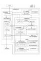
- FIG. 2 is a block diagram schematically showing each configuration of the present embodiment. The configuration of the biological information measuring device 1 will be described with reference to FIG.
- the biological information measuring device 1 is a Western-style toilet part 4 provided with a toilet bowl function part 9 and a sanitary washing function part 91 as in a normal toilet, and biological information for measuring biological information such as the state of excreted urine.
- the measurement unit 5 includes a remote control unit 70 that performs various operations on the Western-style toilet 4 and the biological information measurement unit 5 and an input / output unit 7 that includes a print output unit 73 that outputs measurement results.
- the western-style toilet part 4 incorporates a water supply control means 21 for controlling the supply of water used for cleaning and measurement from the outside.
- the city water 20 to be supplied is branched by the water supply control means 21 to the toilet bowl function unit 9, the sanitary washing function unit 91, and the biological information measurement unit 5 through the water supply pipes, and supplied. That is, the water supplied to the Western-style toilet unit 4 is supplied to the toilet function unit 9 for toilet cleaning, is supplied to the sanitary cleaning function unit 91 for sanitary cleaning, and is further measured by the biological information measuring unit 5 For use, it is divided and supplied to pipes connected to each.
- the Western-style toilet 4 is provided with a bowl 22 that receives excrement excreted by the user as with a normal toilet, and a trap 24 that communicates the interior of the bowl 22 with a drainage socket 25 through a drainage socket 25. ing.
- a reservoir 23 is formed to prevent bad odors and sanitary pests generated in the drain pipe 26 from entering the toilet.
- the accumulated water mixed with excrement excreted by the user is discharged to the drain pipe 26 outside the apparatus via the drain socket 25.
- the remote controller 70 (remote controllers 71 and 72) is provided with various operation switches for operating the biological information measuring apparatus 1. Each operation of the remote control operation unit 70 is transmitted as an operation signal to the Western-style toilet unit 4 and the biological information measurement unit 5 that are operated by a microcomputer. The frequency and time interval defined in the present application are set and input by the refresh operation setting input unit 74 of the remote control operation unit 70.
- the biological information measurement unit 5 includes a water pressure measurement mechanism unit 51, a measurement start water level formation mechanism unit, a calibration water level formation mechanism unit 82, a calibration water level formation mechanism unit 81, a water replenishment mechanism unit 75, a pipe switching mechanism unit 52, and the like. And a control processing unit 60 are provided.
- the water pressure measuring mechanism 51 measures the pressure (water head pressure) generated by the water level of the stored water 23 through a measurement pipe line that communicates with the stored water 23.
- the measurement start water level formation mechanism forms a water level at the start of measurement.
- the calibration water level formation mechanism unit 82 forms a calibration water level necessary for calibrating the output of the water pressure measurement mechanism unit 51.
- the calibration water level formation mechanism unit 81 creates a calibration water level necessary for creating a water level-water quantity calibration curve based on the relationship between the water level and the water level depending on the shape of the bowl 22.
- the water replenishment mechanism unit 75 supplies water for forming the calibration water level and the measurement start water level described above.
- the pipe switching mechanism unit 52 includes a plurality of switching valves for forming a water flow path necessary for each operation.
- the control processing unit 60 performs various processes such as control of various operations and storage / calculation performed by the entire biological information measurement unit 5 including these mechanisms.
- the stored water level calculation unit 50 that obtains the water level of the stored water 23 that changes due to urination of the subject from the pressure information measured by the water pressure measurement mechanism unit 51 and the stored water level calculation unit 50 are used.
- a stored water amount calculation unit 90 that calculates the amount of stored water in the bowl 22 from the stored water level, and a living body that calculates biological information such as urine volume excreted by the subject, urine specific gravity, and other biological information from the stored water amount information obtained by the stored water amount calculation unit 90
- a calibration water level formation support unit 80 that instructs the operation of the information calculation unit 30, the calibration water level formation mechanism unit 81, and a refresh operation instruction unit 95 that controls a later-described refresh operation for regenerating the calibration water level are provided.
- the stored water level calculation unit 50 measures the pressure (water head pressure) generated by the water level of the stored water 23 using the water pressure measurement mechanism unit 51 via the measurement pipe line communicating with the stored water 23, and the obtained measurement value ( By applying an output-pressure calibration curve representing the relationship between the sensor output and the pressure (water head pressure) obtained in advance to the output), the pressure generated by the water level of the accumulated water 23, that is, the reservoir under atmospheric pressure. Find the water level.
- the sensor output changes due to the aforementioned drift phenomenon.
- a water pressure sensor output calibration unit 59 included in the output calibration means of the embodiment is incorporated in the stored water level calculation unit 50 in order to calibrate the measurement value every time the stored water level is measured.
- the calibration water level formation instructing unit 80 instructs the calibration water level formation mechanism unit 81 to create a calibration water level for creating the relationship between the water level and the water level in the bowl 22 of the Western-style toilet 4 to be used.
- This creation operation is executed and stored when the apparatus is installed. In the procedure, the water pressure due to the water level when the predetermined amount of water is sucked from the bowl 22 by the calibration pump 811 is measured by the water pressure measuring mechanism 51, and the relationship between the water pressure and the water amount is recorded.
- the relationship between the accumulated water pressure and the accumulated water amount in the predetermined water level range of the bowl 22 is learned and stored in the water level-water amount calibration curve storage unit 58.
- the stored water level formed in the bowl 22 is also influenced by the floor inclination of the installation site, the internal pressure of the drainage pipe, and the like. Therefore, the water level-water calibration curve must be created and stored at the time of installation when performing high-accuracy measurement, and it is also rewritten during regular verification.
- the water pressure measurement mechanism unit 51 is included in the pressure measurement unit in the embodiment
- the stored water level calculation unit 50 is included in the stored water level calculation unit in the embodiment
- the calibration water level formation mechanism unit 82 is in the embodiment.
- the water pressure sensor output calibration unit 59 is included in the output calibration means in the embodiment.
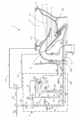
- FIG. 3 is a system configuration diagram schematically showing the overall configuration of the embodiment according to the present invention, and shows a specific configuration of the urination information measuring apparatus 1 according to the present embodiment.
- detailed configurations of the sanitary washing device 91 and the toilet bowl function unit 9 are omitted for convenience of explanation.
- the toilet 4 is connected to a drain pipe 26 via a drain socket 25.
- a reservoir 23 having a sealing function for blocking communication with the drainage pipe 26 by the trap 24 is formed.
- Water supply from an external water supply source such as a water supply is performed by a stop cock 210, a branch fitting 211, and a three-way valve 213 included in the water supply control means 21 and a rim water supply pipe 214 directed to the rim water spout 215 and an implementation described later.
- Water supply to the replenishing tank 61 is performed by the on-off valve 611, and a predetermined amount is detected by the float switch 612, and water supply is stopped.
- the overflow pipe 64 discharges to the drain pipe 26 via the drain pipe connecting pipe 562 via the trap tank 551 on the way, causing water leakage to the outside of the apparatus. Considered not to.
- a branching device 542 is provided in the middle of the jet water supply pipe 216, and a pipe 543 that communicates with the pressure sensor 512 and corresponds to the measurement pipe of the embodiment is provided. It is connected.
- a branching tool 545 is provided in the middle of the pipe line 543, and a supplementary water pipe 63 communicating with the supplementary water tank 61 is branched and connected.
- An on-off valve 522 for opening and closing the water refilling pipe 63 is provided in the middle.
- a branching tool 546 is further provided in the middle of the pipe 543, and an opening / closing valve 525 for opening and closing the pipe and a calibration pump 811 for sucking the accumulated water 23 are provided in the middle, and communicates with the trap tank 551.
- a pipeline 812 is connected.
- the trap tank 551 is a drain tank that performs a trap function for the drain pipe in order to discharge surplus water such as overflow water generated by the operation of each part to the drain pipe 26.
- the pipe line 543 is connected to a pressure sensor 512 included in the pressure measuring means in the embodiment, and further, a water level forming pipe 511 included in the water column forming means in the embodiment is connected to the pressure sensor 512.
- the water level forming pipe 511 is provided with an opening that is extended into the trap tank 551 and opened to the atmosphere, and is a vertical pipe portion having an atmosphere open end 511a at a predetermined height in the vertical direction in the embodiment.
- a U-shaped pipe line system having both ends opened together with the bowl 22 communicated with the measurement pipe line is formed.
- the water level forming pipe 511 in the present embodiment fluidically attenuates the vibration component transmitted in the measurement pipe line due to the undulation of the water surface of the accumulated water 23 due to urination, and the pressure sensor 512 makes the water pressure of the accumulated water 23 more accurate. Therefore, it is configured to be formed of a narrow tube having a predetermined inner diameter.
- the water level forming pipe 511 also has a function of an output calibration pipe for calibrating the output of the pressure sensor 512.
- the stored water level during measurement standby is the measurement start water level Y
- the stored water level 23 is set to the measurement start water level Y by using the toilet flushing function of the toilet function unit 9.
- the ball 22 is washed by water discharged from the pipe line 214, and then all the accumulated water 23 is drained by a siphon phenomenon induced by the jet water discharged from the jet water outlet 541 by water supply from the pipe line 216. It is discharged to the pipe 26. Thereafter, the water 23 is supplied by the water discharged from the rim water spouting port 215 until the water level X is exceeded.
- the on-off valve 524 and the on-off valve 525 are closed, the on-off valve 521 and the on-off valve 522 are opened, and the replenishing water tank 61 and the accumulated water 23 are communicated with each other through the water refilling pipe 63 and the pipe 543.
- the water supply pump 62 is operated at a predetermined water supply rate for a predetermined time, and the water stored in the water replenishment tank 61 is discharged from the jet water outlet 541, whereby the stored water level is changed to the breaking water level X of the trap 24.
- the operation of setting the measurement start water level Y higher by a predetermined amount is performed.
- the open / close valves 521 and 525 are closed and the open / close valves 522 and 524 are opened.
- the water supply pump 62 is operated to guide the water stored in the water supply storage tank 61 to the water level forming pipe 511, and overflow from the atmosphere open end 511a into the trap tank 551 to enter the water level forming pipe 511. Is filled with water, a water column having a fixed length to the open end of the water level forming pipe 511 is created.
- the reason for waiting in the water level forming tube 511 to be full is to take into account that the subject patient includes a disease that the patient cannot withstand urination.
- the water level forming pipe 511 is filled with the water state in advance and waits. However, consideration is given so that the measurement operation can be immediately shifted to.
- the pressure head 512 measures the water head pressure of the water column of a certain height set by the water level formation pipe 511 immediately before the measurement in accordance with the measurement start operation of the subject. By doing so, the output calibration of the relationship between the output value of the pressure sensor 512 and the water level is performed in consideration of environmental variation factors such as atmospheric pressure and temperature at the time of calibration, and corresponding to the reference water level value.
- the opening end surface of the water level forming pipe 511 is not facing upward but is facing sideways. This is because when the pipeline is opened and closed upward, the water surface becomes convex upward or concave due to surface tension in a gravitational environment, making it impossible to create a stable absolute water level. .
- the water level forming pipe 511 In order to reduce the amount of error, there is a method of reducing the cross-sectional area of the water level forming pipe 511, but the water level forming pipe 511 also has a function of releasing the pressure wave generated in the pipe 543 to be guided, and is necessary. The pipe cannot be made thinner than that.
- the water level forming pipe 511 has a function of releasing the pressure wave and a function of calibrating the absolute value.
- the on-off valves 521 and 524 are opened to connect the accumulated water 23 and the pipe 543 of the water level forming pipe 511 so that the measurement start water level Y and the water level in the water level forming pipe 511 are at the same height.
- the change in the water level is measured by the pressure sensor 512.
- the trap tank 551 has a drainage pipe connecting line 562 extending from a position where a sealed water is formed inside to drain the overflow water from the water level forming pipe 511 at the time of output calibration to the drainage pipe 26.
- a drainage pipe connection port 563 provided in the drainage socket 25 is connected. Thereby, it functions as an edge cutting means that seals the connection pipe line with the drain pipe by water sealing.
- the urination information measuring device 1 of the present embodiment has a function of measuring the correspondence between the water level of the stored water 23 and the amount of stored water at the installation site and storing it as a calibration relationship in the embodiment.
- a calibration pump 811 that is a fixed-aspiration pump capable of sucking an arbitrary amount is provided.
- the calibration pump 811 sucks the accumulated water 23 using the pipe line 543 which is the measurement pipe line in the embodiment, and can discharge it toward the drain pipe via the trap tank 551 and the drain pipe connecting pipe line 562.
- the accumulated water 23 is sucked and discharged from the bowl 22 by a predetermined amount by the calibration pump 811.
- the water head pressure generated by the stored water level is measured by the pressure sensor 512 to calculate the water level. By doing so, the calibration relationship between the stored water level and the stored water amount is acquired.
- the calibration curve storage unit 31 may store the calibration curve for each device. For example, this configuration can be applied to a toilet bowl in which at least the bowl portion is made of resin.
- the occurrence of an error in the water level measurement value in the apparatus configuration to which the embodiment is applied is caused by the formation of bubbles of dissolved air from the water inside the water level forming pipe 511, which is caused by being left unused for a long period of time. It is.
- the output of the pressure sensor 512 is calibrated by the water level forming pipe 511 that is full of water every time measurement is performed. However, if the measurement interval is extended for a long time or the environmental temperature rises, bubbles may be generated from the water in the measurement tube 512 and collected at the top of the measurement tube 512.
- the generated bubbles accumulate at the top of the water level forming pipe 511 and grow into large bubbles, which are then filled to the full level. Lower the internal water column by the bubble diameter. As a result, the calibration output of the pressure sensor 512 is lowered.
- the bubbles generated in the conduit 543 for guiding pressure may inhibit the pressure transmission and prevent the pressure from being correctly transmitted, or may cause a pulsation in the pressure fluctuation over time. Further, when the bubbles are caught by the connecting portion of the pressure sensor 512, a damper is formed with respect to the transmitted pressure, and in this case, the output of the pressure sensor is lowered.
- the open / close valve 522 and the open / close valve 524 are opened to supply the water in the replenishing tank 61 to the accumulated water pressure level forming pipe 511, and the bubbles appearing inside the water level forming pipe 511 are pushed out and discharged by being left for a long time.
- the refresh operation is performed. Since the electrical output of the pressure sensor 512 is affected by the temperature change in the environment, a state in which the water temperature in the measurement tube greatly fluctuates must be avoided when performing this operation. For this reason, in this embodiment, the water that is considered to have substantially the same temperature as the water in the measuring tube is used to pass water for 1 second to 2 seconds using the stored water in the water retention tank 61 inside the biological information measuring unit 5.
- the water level forming pipe 511 is moved. Bubbles in the water level forming pipe 511 closest to the pressure sensor 512 are sequentially pushed out into the trap tank 551 and disappear in the course of this operation, so that the water level forming pipe 511 is filled with only water up to the upper atmospheric open end. It becomes a water column in the state and an accurate calibration water level as designed is obtained.
- the air opening end 511a of the water level forming pipe 511 is not in a simple form opened upward, but is located in the trap tank 551.
- output calibration in the embodiment uses what is called water head pressure, this state does not affect calibration accuracy.
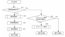
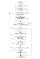
- FIG. 4 is a flowchart showing a flow of operation of the example according to the embodiment.
- the presence / absence of a measurement start operation is monitored. That is, the presence / absence of a measurement start operation is determined in S11, and if there is a measurement start operation, the biological information measurement operation starting from S12 is started.
- the biological information measurement operation is divided into a pre-measurement operation in S12, a urination information measurement in S13, and a post-measurement operation in S14. Details of the pre-measurement operation and the post-measurement operation related to the embodiment will be described later.
- the process proceeds to S21, and it is confirmed whether or not the conditions for performing the set refresh operation are met. If it matches, a refresh operation is performed in S22. The specific operation of the refresh operation will be described in detail later. If not, the process returns to the beginning, and it is determined again whether or not the measurement start operation of S11 is performed.
- the biological information measurement operation may be read as an operation for other purposes.
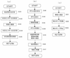
- FIG. 5 shows detailed steps of each operation described in FIG.
- FIG. 5A is an operation flow related to the pre-measurement operation in S12.
- the output voltage of the pressure sensor 512 is measured as a calibration water level measurement.
- the water level in the water level forming pipe 511 is the full water level up to the atmosphere open end 511a formed in the post-measurement operation performed at the previous measurement, and the calibration water level of the predetermined water level in the embodiment. It has become.
- S122 is a step of performing water level sensor output calibration, and an output calibration operation for comparing the output voltage of the pressure sensor 512 with the full water level of the water level forming pipe 511 is performed.
- the on-off valve 521 and the on-off valve 524 existing in the pipe A are opened in S123, the pipe line between the ball 22 and the water level forming pipe 511 is communicated, and the ball 22 and the water level forming pipe 511 are connected. Make the water level the same. In this state, the water level forming pipe 511 functions as a part of the water level measuring means in the water level measuring device for the stored water.
- S124 the output voltage of the pressure sensor 512 is measured as the water level sensor output measurement.
- S125 is a step of confirming the measurement start water level before urination, and from which water level position the urine information is measured in a pre-stored water level-water quantity calibration curve indicating the calibration relationship between the stored water level and the accumulated water level. Perform processing such as origin correction.
- FIG. 5B is an operation flow related to the post-measurement operation in S14. After the series of urination information measurement operations in S13 is completed, the ball 22 is washed in S141 by the user's toilet cleaning operation, and then the water stored in the balls 22 is siphoned by the water discharged from the jet outlet 511. 23 is discharged toward the drain pipe 26.
- S142 is an operation step similar to a series of operations of toilet flushing for recondensing the trap 24 in a broken state in order to seal the trap 24 again.
- S143 is a step in which the on-off valve 521 and the on-off valve 522 are opened to form the pipe line B between the replenishing tank 61 and the ball 22 in order to form the measurement start water level Y used for the next measurement.
- the water replenishment pump 62 is driven to supply water in the water tank 61, and the water level of the stored water 23 is replenished until it reaches a predetermined measurement start water level Y.
- the open / close valve 521 is closed in S145 in order to set the water level of the water level forming pipe 511 to the calibration water level that is the water level for calibrating the output of the pressure sensor 512.
- the open / close valve 524 is opened to switch the pipe line communicating with the pipe line C.
- the water replenishing pump 62 is driven to supply a predetermined amount of water to the water level forming pipe 511, whereby the water level forming pipe 511 becomes full and excess water is discharged to the trap tank 551.
- S147 is a step in which the water replenishment pump 62 is closed, the on-off valve 524 is closed, and the pipeline C is closed. In this state, the water level forming pipe 511 is maintained in a full water state, and functions as a calibration pipeline in the embodiment.
- FIG. 5C is an operation flow relating to the refresh operation in S22.
- step S221 the on / off valve 521 and the on / off valve 524 are opened to form the pipe C in order to drain the water stored in the replenishing tank 61 through the water level forming pipe 511.
- step S222 the water replenishing pump 62 is operated for a predetermined time to supply a predetermined amount of water in the water replenishing tank 61 toward the water level forming pipe 511.
- the water replenishment pump 62 is stopped in S223.
- water is filled up to the upper end of the water level forming pipe 511, and a calibration water level having a predetermined height is re-formed.
- the water replenishing pump 62 may not be operated, and the water may flow only by the head pressure of the water replenishing tank 61.
- the predetermined timing for performing the refresh operation in the embodiment which is the refresh operation condition described above may be changed according to the medical condition. For example, when it is not used at night as in a doctor's office and is frequently used only in the daytime, it is recommended to perform a refresh operation at a predetermined time in the embodiment, that is, for example, at 6:00 am before medical examination time. The Further, if the medical institution has a low use frequency and a long use interval, the refresh operation is performed at a predetermined time interval in the embodiment. However, the refresh operation itself is not necessary when it is expected to be used 24 hours a day, such as when used in an inpatient ward of a large hospital. You may make it provide the selection means which can select embodiment of operation
- FIG. 6 is a flowchart showing the flow of operation of another example according to the embodiment.
- S31 is a step in which the subject inputs an instruction to start biological information measurement such as urine flow rate.
- S32 is a step of measuring the position of the measurement start water level, which is the water level in the bowl when starting the measurement.
- S33 is a step of confirming whether or not the measured measurement water level has changed by a predetermined value or more from a pre-formed water level, and confirms whether or not a water level change due to mischief or cleaning has occurred. If there is no deviation greater than the predetermined value, it means that normal measurement is possible, and the routine branches to step 50 to start normal measurement operation.
- step 34 When the deviation of a predetermined value or more is confirmed, at step 34, it is informed that an abnormality has occurred and guides the subsequent operation selection. Specifically, whether to stop the measurement or reset the measurement start water level is displayed, and the subject selects an operation in step S35. In this case, on the assumption that the measurement accuracy is lowered, there is an option to force the measurement without resetting the water level. Considering that excretion may not be possible, in this case, the process proceeds to step S50.
- Step S36 is a step of determining whether or not water level resetting has been selected. When water level resetting is selected, toilet flushing is performed, and then a resetting operation for creating a measurement start water level is executed in step S37. In step S36, when the water level resetting is not selected, it is considered that the measurement stop is selected, and the measurement sequence is ended. When the resetting is completed, the resetting is completed and measurement preparation is completed in step S38, and a guide for waiting for a measurement start instruction is issued.
- Step S39 is a step of performing an operation instruction operation. When the start of measurement is determined in step S40, a normal measurement operation is performed in step S50.
- step S51 the measurement sequence is terminated in step S51.
- this algorithm confirms the deviation of the measurement start water level with the measurement operation as a trigger.
- the trigger may be set at a time interval, for example, every 10 minutes, and the measurement start water level may be continuously checked. If there is a measurement start operation by the subject during that time, the measurement action is performed by interrupting the flowchart.
- a remote control operation unit 70 may be provided with a changeover switch for selecting either measurement stop or resetting of the measurement start water level.
- a maintenance information display unit may be provided in the remote control operation unit to notify the necessity of maintenance of the apparatus itself when the cleaning water supply means 21 fails and water cannot be stopped properly.
- the present embodiment described above is a water level measuring device incorporated in a biological information measuring device.
- the embodiment is a water level measuring device having a function of calibrating the pressure of the pressure measuring means, with the measurement target being the water level of the toilet bowl. Applies to
- the embodiment even if the operation of the water level measuring device is stopped for a long time or the environmental temperature of the installation location is changed, it is possible to maintain the same measurement accuracy as when performing measurement constantly. The effect that it can be obtained. Furthermore, when an abnormality occurs in the measurement environment, an appropriate countermeasure can be taken by notifying the outside of the abnormality.
- Zet water supply pipe 511 Water level forming pipe 511a ... Atmospheric open end (water level forming pipe) DESCRIPTION OF SYMBOLS 512 ... Pressure sensor 521 ... Open / close valve 522 ... Open / close valve 524 ... Open / close valve 525 ... Open / close valve 541 ... Zette water outlet (measurement communication port) 543 ... Pipe line 551 ... Trap tank 561 ... Drain pipe pressure measuring sensor 562 ... Drain pipe connection pipe 563 ... Drain pipe connection port 611 ... On-off valve 612 ... Float switch 811: Calibration pump 812: Calibration pipeline X ... Broken water level Y ... Measurement start water level Z ... Post urine water level H ... Overflow water level
Landscapes
- Physics & Mathematics (AREA)
- Fluid Mechanics (AREA)
- General Physics & Mathematics (AREA)
- Bidet-Like Cleaning Device And Other Flush Toilet Accessories (AREA)
- Sanitary Device For Flush Toilet (AREA)
- Measurement Of Levels Of Liquids Or Fluent Solid Materials (AREA)
Abstract
水位測定装置は、溜水を蓄えて排泄物を受けるボウルを備えた大便器と、上端を大気解放端とした立管状の水位形成管と、前記水位形成管内の水位によって生じる圧力を測定する圧力計測手段と、前記水位形成管の下端部と前記ボウル内の溜水とを連通し前記測定水位形成管内に前記溜水の水位と同一水位の測定水位を形成する測定水位形成手段と、前記測定水位における前記圧力計測手段によって計測される圧力計測値に基づいて前記溜水の水位を算出する溜水水位算出手段と、前記水位形成管に給水し前記水位形成管内に所定の高さの校正水位を形成する校正水位形成手段と、前記校正水位における前記圧力計測手段の出力値に基づいて前記圧力計測手段の出力を校正する出力校正手段と、を有する水位測定装置において、前記校正水位形成手段に所定のタイミングで、前記校正水位を再形成するリフレッシュ動作を行なわせるリフレッシュ動作制御手段と、をさらに備えた。
Description
本発明の実施形態は、洋風大便器のボウル内の溜水水位を測定することに係り、特に溜水水位を高精度で安定して測定することに好適な水位測定装置に関する。
従来の大便器のボウル内の溜水の水位測定装置として、洋風大便器のボウル内への排泄時における溜水の水位を測定し、予め取得した溜水水位と溜水量との関係である検量線を利用して溜水変化量を求めることによって、排泄された尿量や単位時間当たりの尿量である尿流率を測定する排尿情報測定装置がある(例えば、特許文献1参照)。
この装置におけるボウル内の溜水の水位測定は、溜水によって生じる水圧を直接測るのではない。その代わりに、ボウル外に設けた立管状の測定管とボウル内の溜水とを連通させたときに測定管内に形成される水柱によって生じる水圧(水頭圧)を、測定管に連通させた圧力センサを用いて電気的出力に変換して計測している。
一般に、測定管路を用いて離れた位置で行う形態の圧力測定においては、測定対象の圧力を圧力センサに伝達するための圧力伝達媒体が測定管路内に必要となる。しかし、空気等の気体では、その圧縮性が応答性等の面で測定精度に影響を与える。従って、液体を圧力伝達媒体として使用することも多い。しかし、その場合、測定管路の観測側(圧力センサ側)が閉塞端の構成では、装置組み立て時に測定管路内に残留する空気の除去が困難である。このため、この特許文献1記載の装置のように、圧力センサ側を装置組み立て後でも空気抜きが容易な大気開放端としたU字状管路にすることが多い。
さらに特許文献1記載の装置は、この圧力伝達媒体を装置自体が取り扱う水とすることによって、装置設置施工時に現場でも問題なく空気抜きが行なえる構成としている。即ち、この装置は、施工後、測定管路の溜水側の連通を遮断した状態で圧力センサ側に給水を行ない大気開放端から溢流させて測定管路内の残存空気を水と一緒に除去することによって、測定管路内を圧力伝達媒体だけで充満させる構成を採用している。この動作の際に排出される圧力伝達媒体である水の処理は、装置が本来備えている排水管路で系外に搬送することで簡単に行える。
また、特許文献1記載の装置では、便器のボウル内の溜水量を算出するために必要な溜水水位を水位によって生じる水圧(水頭圧)を計測して求めている。しかし、測定時の溜水表面の水平方向の断面積が測定対象となる溜水量の変化範囲に対してかなり大きいため、観測対象となる水圧変化量は小さくなる。従って、このような形態で使用される圧力測定系としては、高精度のものが求められる。
一方、一般的に圧力測定系で使用される圧力センサは、使用時の雰囲気温度によって出力状態が変化するのを防止するため温度補償機能を持っている。しかし、このような構成の水位測定装置に使用した場合は、雰囲気の温度だけでなく、直接、接する圧力伝達媒体である水の温度にも影響を受けるため、完全に補償することは出来ない。その結果として、圧力センサの圧力-出力関係が微小ながら変化するドリフト現象が発生することが避けられない。従って、圧力センサの圧力-出力関係を予め求めた圧力-出力検量線に基づいて溜水水位値を算出すると実際の溜水水位とは無視できない程度に異なることとなる。そのため、前述した特許文献1記載の装置では、高精度測定を行う際には一般的に行なわれている圧力センサ出力の校正を行う構成を併設している。
具体的には、測定管の開放端を、測定する溜水水位変動範囲よりも高い所定位置に形成する。また、この測定管に任意の量の給水を行なえる給水手段を用意し、溜水側との連通を遮断した状態で給水を行なって立管の中を満水状態にしてセンサ連通位置から開放端までの一定高さの水柱を形成する。そして、この一定高さの水柱の水位を校正用水位として計測した時のセンサ出力を基準値としてセンサーの出力の校正を行う構成を採用している。
また、この校正用水位を形成する一連の動作は時間を必要とするため、測定が終わったあとに次回の校正用として校正用水位を形成しておく。そして、本来の溜水水位測定を行う都度、測定開始直前に測定前準備動作として、この校正用水位のセンサ出力値を計測してセンサーの出力の校正を行うことで測定誤差の発生を防止している。
また、この校正用水位を形成する一連の動作は時間を必要とするため、測定が終わったあとに次回の校正用として校正用水位を形成しておく。そして、本来の溜水水位測定を行う都度、測定開始直前に測定前準備動作として、この校正用水位のセンサ出力値を計測してセンサーの出力の校正を行うことで測定誤差の発生を防止している。
ところが、以上で述べたような構成を持った装置では、校正用水位を形成したままでの装置の不使用状態が長期間継続すると水位が変化してしまう。そして、校正基準水位となる校正用水位が変化したまま校正を行う結果、溜水水位の測定結果に誤差を生じてしまうという問題があることが本願発明者の確認試験で判明した。
この校正用水位変化の原因としては、前述した測定管内の水に溶存した空気が待機時間の経過とともに、徐々に気泡となって出てきて測定管内の上端の大気開放端部付近に気泡の固まりとなって付着し、管内の水を管外に押し出すことによる管内の水位低下によることが確認された。さらには、大気開放端部からの管内の水の蒸発や、水中に存在する気泡による圧力伝達に対する緩衝効果も可能性としては考えられた。
また、排尿情報測定装置の不使用状態が長期間継続した場合の別の不具合現象として、予め形成しておいた測定を開始するときの溜水水位である測定開始水位が待機中に高くなり、結果として、最大で測定開始水位から溢流水位までの測定可能範囲が小さくなるということも判明した。
この現象の原因は、例えば、イタズラでボウル内に水を足された場合や、大便器自身の給水弁に止水不良による漏水が生じた場合などが考えられた。
本発明は、上記問題を解決するためになされたもので、本発明の課題は、便器のボウルの溜水を対象とする圧力測定手段を用いた水位測定装置の測定精度の維持に関するものである。
上記目的を達成するために請求項1記載の発明は、溜水を蓄えて使用者の排泄物を受けるボウルを備えた大便器と、上端を大気解放端とした立管状の水位形成管と、前記水位形成管内の水位によって生じる圧力を測定する圧力計測手段と、前記水位形成管の下端部と前記ボウル内の溜水とを連通し前記測定水位形成管内に前記溜水の水位と同一水位の測定水位を形成する測定水位形成手段と、前記測定水位における前記圧力計測手段によって計測される圧力計測値に基づいて前記溜水の水位を算出する溜水水位算出手段と、前記水位形成管に給水し前記水位形成管内に所定の高さの校正水位を形成する校正水位形成手段と、前記校正水位における前記圧力計測手段の出力値に基づいて前記圧力計測手段の出力を校正する出力校正手段と、を有する水位測定装置において、前記校正水位形成手段に所定のタイミングで、前記校正水位を再形成するリフレッシュ動作を行なわせるリフレッシュ動作制御手段と、をさらに備えたことを特徴とすることにより、圧力測定手段の出力校正動作において基準となる校正水位が更新されて常に許容範囲内の水位に保たれることとなることで、圧力測定手段の出力校正を正確に行うことが可能となるため、便器ボウル内の溜水水位の測定精度が低下することが無くなる。
また、請求項2記載の発明は、前記リフレッシュ動作が前記水位形成管への補水によって前記水位形成管内の水を前記大気解放端からオーバーフローさせるものであることを特徴とすることにより、校正水位が立管の先端位置に物理的に限定されるため、再形成する際の外部からの給水動作における給水量の上限が無くなり給水量の制御が簡単な構成で可能となる。
また、請求項3記載の発明は、水を貯留する補水タンクをさらに備え、前記補水が前記補水タンク内の貯留水によっておこなわれることを特徴とすることにより、少なくとも装置の稼働時以外の時間は滞留している溶存空気が少ない水を使用することとなるため、その後の測定時までの気泡発生が少なくなり、校正水位の低下現象の発生を抑制することが可能となる。
また、請求項4記載の発明は、前記所定のタイミングは、定められた時刻であることを特徴とすることにより、医療機関の診療前に測定状態を良好な状態とすることが可能であり、測定精度低下を懸念する必要が無くなる。
また、請求項5記載の発明は、前記所定のタイミングは、定められた時間間隔であることを特徴とすることにより、医療機関の診察時間や診療状態に左右されることなく、精度低下を懸念することが無くなる。
また、請求項6記載の発明は、溜水を蓄えて使用者の排泄物を受けるボウルを備えた大便器と、下端が前記ボウル内の溜水と連通され上端を大気解放端とした立管状の水位形成管と、前記水位形成管内の水位によって生じる圧力を測定する圧力計測手段と、前記水圧測定圧力計測手段によって計測される圧力計測値に基づいて前記溜水の水位を算出する溜水水位算出手段と、前記水位形成管内に所定の高さの校正水位を形成する校正水位形成手段と、前記校正水位における前記圧力計測手段の出力値に基づいて前記圧力計測手段の出力を校正する出力校正手段と、を有する水位測定装置において、溜水水位測定開始信号受信時に、前記溜水水位算出手段によって求められた溜水水位が所定の水位より所定値以上乖離しているとき、異常状態を報知する異常報知手段をさらに備えたことを特徴とすることにより、測定範囲が正常ではない状態を知ることによって、メンテナンス等の適切な処置を行なえるようになる。
本発明の実施形態によれば、水位測定装置の稼働が長時間停止されたり、設置場所の環境温度が変化したりしたとしても、定常的に測定を行っている時と同様の測定精度を維持することができるという効果が得られる。
さらにまた、測定環境に異常が生じた場合、それを外部へ報知することによって、適切な対応処置をとることが可能となる。
さらにまた、測定環境に異常が生じた場合、それを外部へ報知することによって、適切な対応処置をとることが可能となる。
図1は本発明の実施形態を実施した実施例の一つである生体情報測定装置全体を示す斜視図である。図1を使用して、本実施例における生体情報測定装置の全体構成について以下に述べる。
本実施例における生体情報測定装置1は、便器洗浄機能や衛生洗浄機能などの通常の便器機能部9を一体的に備えた洋風大便器4と、洋風大便器4の背後に設置されたキャビネット18と、内部に被験者が生体情報測定装置1の各種の動作を指示する操作を行なったり、得られた測定結果等を表示するために壁に設けられたリモコン操作部70と、測定結果等をプリントアウトするプリンタ73と、を備えている。
キャビネット18の内部には、ボウル内の水位を測定することによって、被験者が排泄する尿の量である尿量や、単位時間当たりの排泄速度である尿流率等の排尿情報の測定を行う生体情報測定部5が収納されている。
リモコン操作部70は、生体情報測定用のリモコン72と、衛生洗浄装置を備えた大便器操作用のリモコン71と、を備えている。
リモコン72は、被験者がトイレに入室し排尿情報を測定する時にスイッチ操作するものであり、測定開始を指示する測定開始スイッチや、排尿が終了したことを指示する排尿終了スイッチ等が設置されている。さらに、実施形態に係るリフレッシュ動作仕様の設定内容を使用状態等に合わせて変更する設定変更スイッチも設置されている。
リモコン72は、被験者がトイレに入室し排尿情報を測定する時にスイッチ操作するものであり、測定開始を指示する測定開始スイッチや、排尿が終了したことを指示する排尿終了スイッチ等が設置されている。さらに、実施形態に係るリフレッシュ動作仕様の設定内容を使用状態等に合わせて変更する設定変更スイッチも設置されている。
図2は、本実施例各構成を模式的に示したブロック図である。図2を使用して、生体情報測定装置1の構成を説明する。
生体情報測定装置1は、通常の大便器と同様に便器機能部9と衛生洗浄機能部91とを備えた洋風大便器部4と、排泄される尿の状態等の生体情報を測定する生体情報測定部5と、洋風大便器4及び生体情報測定部5に対する各種操作を行うリモコン操作部70や測定結果を出力するプリント出力部73を備えた入出力部7と、を備えている。
洋風大便器部4には、洗浄や測定に使用する水の外部からの供給を制御する給水制御手段21が組み込まれている。供給される市水20は、給水制御手段21によって給水管路を介して便器機能部9と衛生洗浄機能部91と生体情報測定部5とに分岐されて各々供給される。即ち、洋風大便器部4に供給された水は、便器機能部9に便器洗浄用として供給され、また、衛生洗浄機能部91に衛生洗浄用として供給され、さらに生体情報測定部5には測定用として各々に接続された管路に分流して供給される。
洋風大便器4には、通常の大便器と同様に使用者の排泄した排泄物を受けるボウル22や、ボウル22内を排水ソケット25を介して建物の排水配管26へ連通させるトラップ24が設けられている。そして、ボウル22内には排水配管26内部で発生した悪臭や衛生害虫などがトイレ内に侵入することを防止するための溜水23が形成される。使用者の排泄した排泄物混じりの溜水は、排水ソケット25を経由して装置外部の排水配管26に排出されるようになっている。
リモコン操作部70(リモコン71、72)には、生体情報測定装置1を動作させるための各種の操作スイッチが設けられている。リモコン操作部70の各操作は、操作信号としてマイコンで動作する洋風大便器部4と生体情報測定部5とに伝えられる。本願で規定する、どのような頻度や時刻間隔でリフレッシュ動作を実施するかは、リモコン操作部70のリフレッシュ動作設定入力部74で設定入力される。
生体情報測定部5には、水圧測定機構部51、測定開始水位形成機構部、校正水位形成機構部82、検量水位形成機構部81、補水機構部75、管路切替機構部52などの各機構部と、制御処理部60と、が設けられている。
水圧測定機構部51は、溜水23の水位によって生じる圧力(水頭圧)を溜水23と連通する測定管路を介して計測する。測定開始水位形成機構部は、測定開始時の水位を形成する。校正水位形成機構部82は、水圧測定機構部51の出力を校正するために必要な校正水位を形成する。検量水位形成機構部81は、ボウル22の形状に依存する溜水水位と溜水量との関係を水位-水量検量線を作成するために必要な検量水位を作成する。補水機構部75は、前述した校正水位と測定開始水位を形成するための水を供給する。管路切替機構部52は、各動作に必要な水の流路を形成するための複数の切換え弁を備えている。制御処理部60は、これら各機構部を含む生体情報測定部5の全体で行われる各種動作の制御や記憶・演算等の各種処理を行う。
水圧測定機構部51は、溜水23の水位によって生じる圧力(水頭圧)を溜水23と連通する測定管路を介して計測する。測定開始水位形成機構部は、測定開始時の水位を形成する。校正水位形成機構部82は、水圧測定機構部51の出力を校正するために必要な校正水位を形成する。検量水位形成機構部81は、ボウル22の形状に依存する溜水水位と溜水量との関係を水位-水量検量線を作成するために必要な検量水位を作成する。補水機構部75は、前述した校正水位と測定開始水位を形成するための水を供給する。管路切替機構部52は、各動作に必要な水の流路を形成するための複数の切換え弁を備えている。制御処理部60は、これら各機構部を含む生体情報測定部5の全体で行われる各種動作の制御や記憶・演算等の各種処理を行う。
制御処理部60には、水圧測定機構部51によって計測される圧力情報から被験者の排尿によって変化する溜水23の水位を求める溜水水位算出部50や、溜水水位算出部50で求められた溜水水位からボウル22内の溜水量を算出する溜水量算出部90や、溜水量算出部90で求められた溜水量情報から被験者の排泄した尿量や尿比重他の生体情報を算出する生体情報算出部30や、検量水位形成機構部81の動作を指示する検量水位形成支持部80や、校正水位を再形成する後述するリフレッシュ動作を制御するリフレッシュ動作指示部95が設けられている。
溜水水位算出部50は、溜水23の水位によって生じる圧力(水頭圧)を溜水23と連通する測定管路を介して水圧測定機構部51を用いて計測し、得られた計測値(出力)に予め求められているセンサ出力と圧力(水頭圧)との関係を表した出力-圧力検量線を適用することによって、溜水23の水位によって生じる圧力、即ち、大気圧下での溜水水位を求める。しかし、センサ出力は、前述したドリフト現象を起こして変化する。このため、溜水水位測定の都度で測定値を校正するために実施形態の出力校正手段に含まれる水圧センサ出力校正部59が、溜水水位算出部50に組み込まれている。
ボウル22が陶器である場合には特に個体毎の形状寸法バラツキが大きい。このため、検量水位形成指示部80は、使用する洋風大便器4のボウル22における溜水水位と溜水量との関係を作成するための検量水位作成を検量水位形成機構部81に指示する。この作成動作は、装置設置時に実行されて記憶される。その手順は、所定量の水を検量ポンプ811によってボウル22内から吸引させた時の溜水水位による水圧を水圧測定機構部51で計測して溜水圧と溜水量との関係を記録する。この一連の動作を複数回重ねて行うことによって、ボウル22の所定水位範囲における溜水圧と溜水量との関係を学習し、水位-水量検量線記憶部58に記憶する。ボウル22内に形成される溜水水位は設置現場の床傾きや排水配管の内圧状況等にも影響される。このため、水位-水量検量線は高精度測定を行う場合は設置時の作成・記憶が不可欠であり、定期的な検定時に書き換えも実施される。
以上説明したように、水圧測定機構部51は実施形態における圧力計測手段に含まれ、溜水水位算出部50は実施形態における溜水水位算出手段に含まれ、校正水位形成機構部82は実施形態における校正水位形成手段に含まれ、また水圧センサ出力校正部59は実施形態における出力校正手段に含まれている。
図3は、本発明に係る実施例の全体構成を模式的に示すシステム構成図であり、本実施例である排尿情報測定装置1の具体的な構成を示したものである。ただし、衛生洗浄装置91と便器機能部9の詳細構成は説明の便宜上、省略している。
大便器4は、排水ソケット25を介して排水配管26に接続されている。ボウル22内には、トラップ24によって排水配管26との連通を遮断する封水の役割を持った溜水23が形成されている。
上水道などの外部給水源からの給水は、給水制御手段21に含まれる止水栓210と分岐金具211と三方弁213とによって、リム吐水口215に向けたリム給水管路214と、後述する実施形態の測定連通口としても機能するゼット吐水口541に向けたゼット給水管路216と、測定開始水位形成や校正水位形成のために設けられた補水タンク61に向けた尿量計測部給水管路217と、に分岐されて供給されている。
補水タンク61への給水は開閉弁611によって実施され、所定量はフロートスイッチ612で検知され給水が停止される。万一の動作不良発生時は、オーバーフロー管路64によって途中にトラップタンク551を介した排水配管連絡管路562を経由して排水配管26に向けて排出を行い、装置外への漏水等が発生しないよう配慮されている。
本実施例では溜水23の水位を計測するために、ゼット給水管路216の途中には分岐具542が設けられ、圧力センサ512に連通し実施形態の測定管路に相当する管路543が接続されている。管路543の途中には、管路を開閉するための開閉弁521と開閉弁524と、排尿情報測定部5を洋風大便器部から着脱する場合にこの管路を開閉するための開閉弁544と、が設けられている。
またこの管路543の途中には分岐具545が設けられ、補水タンク61と連通する補水管路63が分岐接続されている。そして、その途中にはこの補水管路63を開閉する開閉弁522が設けられている。
管路543の途中にはさらに分岐具546が設けられ、途中に管路を開閉するための開閉弁525と溜水23を吸引するための検量ポンプ811とが設けられ、トラップタンク551に連通する管路812が接続されている。トラップタンク551は、各部の動作に伴って発生するオーバーフロー水等の余剰水を排水配管26に排出させるために排水配管に対するトラップ機能を果たすドレンタンクである。
管路543は実施形態における圧力計測手段に含まれる圧力センサ512に接続され、さらに圧力センサ512には実施形態における水柱形成手段に含まれる水位形成管511が接続されている。水位形成管511は、一端がトラップタンク551の中に延出され大気に開放された開口を備えており、実施形態における鉛直方向に所定の高さで大気開放端511aを有した立管部であり、測定管路で連通されているボウル22と合わせて両端が解放されたU字管状の管路系を形成している。
また、本実施例における水位形成管511は、排尿による溜水23の水面の波立ちによる測定管路内を伝わる振動成分を流体的に減衰させて圧力センサ512が溜水23の水圧をより高精度に計測出来るように、所定の内径を持った細管で形成されている構成となっている。
また、圧力センサ512は、設置された環境の温度変化やセンサ自身の経時変化によって出力が変化する。このため、水位形成管511は、圧力センサ512の出力を校正するための出力校正管の機能をも備えている。
次に本実施例における実際の校正動作について関連する測定動作の一部を含めて以下で説明する。なお、本実施例での測定待機中の溜水水位は測定開始水位Yであり、一連の測定動作が終了すると便器機能部9の便器洗浄機能を利用して溜水水位23が測定開始水位Yにセットされる。
具体的には、先ず、管路214からの吐水によってボール22を洗浄し、次いで管路216からの給水によるゼット吐水口541からのゼット吐水によって誘発されたサイホン現象によって、溜水23を全て排水配管26に排出する。その後、リム吐水口215からの吐水によって、破封水位Xを超えるまで溜水23を供給する。
次に、開閉弁524と開閉弁525とを閉止し、かつ、開閉弁521と開閉弁522とを開放して、補水管路63と管路543とによって補水タンク61と溜水23とを連通させた状態とする。この状態で給水ポンプ62を所定の給水率で所定の時間だけ作動させ、補水タンク61に貯留されている水をゼット吐水口541から吐水させることによって、溜水水位をトラップ24の破封水位Xより所定量高い測定開始水位Yとする動作を行う。
次に、開閉弁524と開閉弁525とを閉止し、かつ、開閉弁521と開閉弁522とを開放して、補水管路63と管路543とによって補水タンク61と溜水23とを連通させた状態とする。この状態で給水ポンプ62を所定の給水率で所定の時間だけ作動させ、補水タンク61に貯留されている水をゼット吐水口541から吐水させることによって、溜水水位をトラップ24の破封水位Xより所定量高い測定開始水位Yとする動作を行う。
測定開始水位Yをセットした後、開閉弁521、525を閉め、開閉弁522、524を開放した状態とする。この状態で、給水ポンプ62を稼働させて給水貯留タンク61に貯留された水を水位形成管511に導き、かつ、大気開放端511aからトラップタンク551の中に溢れさせて水位形成管511の中を満水状態にすることによって、水位形成管511の大気開放端までの高さの固定長を持つ水柱を作り出す。
前述の様に水位形成管511の中を満水状態として待機する理由は、被験者である患者が排尿を我慢することができない疾病が含まれることを配慮してのものである。測定準備動作で水位形成管511の中を満水状態にする工程を実施した場合、そのための時間が準備時間として必要になるため、実施形態では事前に水位形成管511の中を満水状態にして待機し、直ぐに測定動作に移行できるよう配慮されている。次回の測定に当たっては、被験者の測定開始操作に合わせて測定直前の水位形成管511で設定された一定高さの水柱の水頭圧を圧力センサ512で計測する。こうすることで、圧力センサ512の出力値と水位との関係を校正時の大気圧や気温などの環境変動要因を配慮し、基準とした水位値に対応付ける出力校正を行う。
水位形成管511の開口端面は、上向きでは無く、横向きになっている。上向きで管路の開閉を実施した場合、重力環境下では水面が表面張力によって上向きに凸形状になったり、下向きに凹形状になったりして、安定した絶対水位を作ることができないためである。誤差量を減少させるために、水位形成管511の断面積を小さくする方法は存在するが、水位形成管511は導圧する管路543内で発生した圧力波を逃がす働きも有しており、必要以上に管路を細くすることはできない。水位形成管511は、圧力波を逃がす機能と、絶対値を校正するための機能を有していることになる。水位形成管511の開口端面を横向きにすると、管路の開閉時の水面状態が毎回安定するだけでなく、トラップタンク551への接続が容易という利点もある。
次いで、開閉弁521、524を開放して溜水23と水位形成管511の管路543を連通させ、測定開始水位Yと水位形成管511内の水位を同じ高さにしてから、溜水23の水位変化を圧力センサ512で測定する。
なお、トラップタンク551は、この出力校正時の水位形成管511からのオーバーフロー水を排水配管26に排出させるために、内部に封水を形成する位置から延出した排水配管連絡管路562により、排水ソケット25に設けられた排水配管連絡口563に接続されている。これにより、排水配管との接続管路を水封して縁切りを行う縁切り手段として機能している。
また本実施例の排尿情報測定装置1は、設置現場で溜水23の水位と溜水量との対応関係を計測して実施形態における検量関係として記憶する機能を備えている。そのために、任意の量を吸引できる定量吸引タイプのポンプである検量ポンプ811を備える。この検量ポンプ811により、実施形態における測定管路である管路543を使用して溜水23を吸引し、トラップタンク551、排水配管連絡管路562を経て、排水配管に向けて排出できる。
そして、設置現場において溜水23の水位を尿量測定範囲の最高水位以上の水位にした状態から、検量ポンプ811で所定量分ずつ溜水23をボウル22から吸引して排出し、吸引の都度の溜水水位によって発生する水頭圧を圧力センサ512で測定して水位を算出する。こうすることによって、溜水水位と溜水量の検量関係が取得される。
なお、使用する洋風大便器4のボウル面22の形状の個体差が小さくて溜水水位と溜水量の関係が一定な場合は、検量関係計測手段全体を省略し、予め作成した検量線を尿量検量線記憶部31に記憶させておき、装置個別の検量線としてもよい。例えば、少なくともボウル部を樹脂製とした便器であった場合に、この構成を適用することが可能である。
実施形態が適用される装置構成における水位測定値の誤差の発生は、長期間使用されずに放置されたことによって発生する、水位形成管511内部の水からの溶存空気の気泡化に起因するものである。本実施例では前述のように測定の都度、圧力センサ512を満水になった水位形成管511で出力校正する。しかし、長時間測定間隔が開いたり、環境温度が上昇したりすると、測定管512の中の水から気泡が発生して、測定管512の最上部に溜まることがある。その場合、前述の様に水位形成管511の開口端面を横向きにした場合、発生した気泡は水位形成管511の頂上部に溜まって大きな気泡に成長し、引いては満水化した水位形成管511内部の水柱を気泡径の分だけ高さを下げる。その結果として、圧力センサ512の校正出力が低くなってしまう。
導圧する管路543内に発生した気泡は、圧力伝達を阻害して圧力を正しく伝達することを阻害したり、圧力の経時変動に脈動を生じさせることもある。また、気泡が圧力センサ512の連接部に引っかかると、伝達する圧力に対してダンパとなり、この場合も圧力センサーの出力を下げてしまうという不具合が生じる。
実施形態においては、開閉弁522と開閉弁524を開弁させて補水タンク61の水を溜水圧水位形成管511に供給し、長時間放置によって水位形成管511の内部に出現した気泡を押し出し排出することで、リフレッシュ動作が実施される。圧力センサ512の電気的出力は環境の温度変化の影響を受けるため、本動作を実行する際には、測定管内の水温が大きく変動するような状態は避けなければならない。そのため、測定管内の水とほぼ温度が同じと考えられる水として、本実施例では生体情報測定部5の内側にある保水タンク61内の貯留水を用いて1秒から2秒の通水をして、水位形成管511内に移動させる。圧力センサ512に最も近い水位形成管511内の気泡は、この動作の過程で、順次、トラップタンク551に押し出されて消失することによって、水位形成管511内は上端の大気開放端まで水だけの状態の水柱となり設計通りの正確な校正水位が得られる。
なお、本実施例では水位形成管511の大気開放端511aは上方に開放された単純な形態ではなくトラップタンク551の中に位置している状態である。しかし、実施形態においての出力校正はいわゆる水頭圧といわれるものを利用しているため、この状態が校正精度に影響を与えることはない。
図4は、実施形態に係る実施例の動作の流れを示したフローチャートである。
測定動作を行わない待機状態の時には、測定開始操作の有無を監視している。即ち、S11で測定開始操作の有無を判断し、測定開始操作が有った場合はS12以下の生体情報測定動作を開始する。生体情報測定動作は、S12の測定前動作、S13の排尿情報測定、および、S14の測定後動作に分けられるが、実施形態に関係する測定前動作と測定後動作の詳細は後で説明する。S11で測定開始操作が無かった場合は、S21に移行し、設定されているリフレッシュ動作を実施する条件に適合したかどうかを確認する。適合した場合は、S22でリフレッシュ動作を実施する。リフレッシュ動作の具体的な動作は後で詳述する。適合しない場合は最初に戻り、再び、S11の測定開始操作の有無を判断する。実施形態を生体情報測定装置以外の用途の水位測定装置に利用する場合は、生体情報測定動作を他の用途の動作と読み替えればよい。
測定動作を行わない待機状態の時には、測定開始操作の有無を監視している。即ち、S11で測定開始操作の有無を判断し、測定開始操作が有った場合はS12以下の生体情報測定動作を開始する。生体情報測定動作は、S12の測定前動作、S13の排尿情報測定、および、S14の測定後動作に分けられるが、実施形態に関係する測定前動作と測定後動作の詳細は後で説明する。S11で測定開始操作が無かった場合は、S21に移行し、設定されているリフレッシュ動作を実施する条件に適合したかどうかを確認する。適合した場合は、S22でリフレッシュ動作を実施する。リフレッシュ動作の具体的な動作は後で詳述する。適合しない場合は最初に戻り、再び、S11の測定開始操作の有無を判断する。実施形態を生体情報測定装置以外の用途の水位測定装置に利用する場合は、生体情報測定動作を他の用途の動作と読み替えればよい。
図5は、図4で説明した各動作の詳細ステップを示したものである。
図5(a)はS12の測定前動作に関する動作フローである。S121で校正水位計測として圧力センサ512の出力電圧を計測する。この時、水位形成管511内の水位は前回の測定時に行なわれた測定後動作で形成された上端部の大気開放端511aまで満水状態の満水水位であり、実施形態における所定水位の校正水位となっている。S122は水位センサ出力校正を行うステップであり、圧力センサ512の出力電圧と水位形成管511の満水水位とを対比させる出力校正動作を実施する。出力校正動作が終了するとS123で管路Aに存在する開閉弁521と開閉弁524を開放して、ボール22と水位形成管511間の管路を連通させて、ボール22と水位形成管511の水位を同一にする。この状態では水位形成管511は溜水の水位測定装置における水位測定手段の一部として機能している。
S124で水位センサー出力計測として、圧力センサ512の出力電圧を計測する。S125は排尿前の測定開始水位を確認するステップであり、予め記憶されている溜水水位と溜水量の検量関係を示す水位-水量検量線において、どの水位位置から排尿情報を測定するかの測定原点補正等の処理を実施する。
図5(b)はS14の測定後動作に関する動作フローである。S13の一連の排尿情報測定動作が終わった後、使用者の便器洗浄操作によって、S141でボール22の洗浄を行なった後、ゼット吐水口511からの吐水によるサイホン動作により、ボール22内の溜水23を排水配管26に向けて排出する。S142は破封状態になったトラップ24を再び封水するためにボウル内に復水するための便器洗浄の一連の動作と類似の動作ステップである。S143は次回の測定に使用する測定開始水位Yを形成するために、開閉弁521と開閉弁522を開放して補水タンク61とボール22間の管路Bを形成するステップである。
次に、S144において、補水ポンプ62を駆動させ水タンク61内の水を供給して、溜水23の水位を所定の測定開始水位Yとなるまで補水する。溜水水位の測定開始水位Yへの形成が終わると、水位形成管511の水位を圧力センサ512の出力を校正するための水位である校正水位にするために、S145において開閉弁521を閉止して、開閉弁524を開放して連通している管路を管路Cに切り替える。S146において、補水ポンプ62を駆動させて水位形成管511に所定量給水することにより、水位形成管511は満水となり、余剰水はトラップタンク551に排出される。S147は、補水ポンプ62を閉止して、開閉弁524を閉止して管路Cを閉鎖するステップである。この状態では水位形成管511は満水状態で維持されており、実施形態の校正管路として機能している。
図5(c)はS22のリフレッシュ動作に関する動作フローである。S221は補水タンク61に貯留した水を、水位形成管511を介して排水するために、開閉弁521と開閉弁524を開放して管路Cを形成する。次にS222で補水ポンプ62を所定時間だけ稼働させて補水タンク61内の水を水位形成管511に向けて所定量だけ供給する。所定時間経過するとS223で補水ポンプ62を停止させる。この一連の動作によって、水位形成管511の上端まで水が充填され、所定高さの校正水位が再形成される。
この時補水ポンプ62の構造と補水タンク61の配置によっては、補水ポンプ62は稼働させず、補水タンク61のヘッド圧だけで水を流下するようにしても良い。
この時補水ポンプ62の構造と補水タンク61の配置によっては、補水ポンプ62は稼働させず、補水タンク61のヘッド圧だけで水を流下するようにしても良い。
本実施例ではリフレッシュ動作中は水位形成管511は出力校正管として機能させているため、溜水水位測定管としての機能が必要な本来の測定動作を実施できない。従って、前述したリフレッシュ動作条件である実施形態におけるリフレッシュ動作を行う所定のタイミングは、診療状態に合わせて変更しても良い。例えば、医院のように夜間は使用されず、昼間のみ高頻度で使用される場合は、実施形態における予め定められた時刻、即ち、診療時間前の例えば午前6時にリフレッシュ動作を行うことが推奨される。また、使用頻度が低く、使用間隔が長い医療機関であれば、実施形態における予め定められた時間間隔でリフレッシュ動作を行うようにする。しかし、大規模な病院の入院病棟で使用される場合のように、24時間常に使用が想定されるような場合は、リフレッシュ動作自体が不要であり、本動作は行なわないようにするなど、本動作の実施形態を選択可能な選択手段を備えるようにしても良い。
図6は、実施形態に係る別の実施例の動作の流れを示したフローチャートである。
S31は、尿流量等の生体情報測定の開始の指示を被験者が操作入力するステップである。S32は、測定を開始するときのボウル内の溜水の水位である測定開始水位の位置を測定するステップである。S33は、測定された測定開始水位があらかじめ形成されている水位より所定値以上変化していないかを確認するステップであり、イタズラや清掃などによる水位変化などが生じていないかを確認する。所定値以上の乖離が無い場合は通常の測定が可能ということであり、ステップ50に分岐して通常の測定動作を開始する。所定値以上の乖離を確認した場合、ステップ34にて異常が生じていることを報知すると共に、以降の動作選択をガイドする。具体的には、測定を中止するか、測定開始水位を再設定するかを表示し、ステップS35で被験者は動作選択を行う。なお、ここでは測定精度が低下することを納得の上で、水位の再設定を行なわないで測定を強行する選択肢を持っている。排泄は待てないこともあることを配慮したものであり、この場合はステップS50に移行する。
S31は、尿流量等の生体情報測定の開始の指示を被験者が操作入力するステップである。S32は、測定を開始するときのボウル内の溜水の水位である測定開始水位の位置を測定するステップである。S33は、測定された測定開始水位があらかじめ形成されている水位より所定値以上変化していないかを確認するステップであり、イタズラや清掃などによる水位変化などが生じていないかを確認する。所定値以上の乖離が無い場合は通常の測定が可能ということであり、ステップ50に分岐して通常の測定動作を開始する。所定値以上の乖離を確認した場合、ステップ34にて異常が生じていることを報知すると共に、以降の動作選択をガイドする。具体的には、測定を中止するか、測定開始水位を再設定するかを表示し、ステップS35で被験者は動作選択を行う。なお、ここでは測定精度が低下することを納得の上で、水位の再設定を行なわないで測定を強行する選択肢を持っている。排泄は待てないこともあることを配慮したものであり、この場合はステップS50に移行する。
ステップS36は、水位再設定を選択されたかどうかを判断するステップである。水位再設定が選択された場合は、便器洗浄を実施して、次いで測定開始水位を創成する再設定動作をステップS37で実行する。ステップS36は、水位再設定を選択されなかった時は、測定中止を選択したとみなして、測定シーケンスを終了する。再設定が完了すると、ステップS38で再設定が完了して測定準備ができ、測定開始指示を待つ案内を報知する。ステップS39は動作指示操作を行うステップであり、ステップS40で測定開始を判定すると、ステップS50で通常の測定動作を実施する。測定中止と判定した場合は、ステップS51で測定シーケンスを終了する。なお、本アルゴリズムは測定動作をトリガーとして測定開始水位の乖離を確認するものになっている。しかし、トリガーを時間間隔を、例えば10分毎のように設定して、継続的に測定開始水位を確認し続けるものであってもよい。その間に被験者の測定開始操作があった場合は、フローチャートに割り込んで測定行為を実施することになる。
なお、前述の実施形態では排尿情報の測定を優先した仕様で説明した。一方、誤差がある測定は認められないという考え方の場合は、測定開始水位の設定異常が発生した時には、測定機能を停止させることも選定可能である。その場合には、測定中止、または、測定開始水位の再設定のいずれかを選択させるような切替スイッチを、リモコン操作部70に設けても良い。
また、リモコン操作部にメンテナンス情報表示部を設けて洗浄水供給手段21が故障して上手く止水できない等の場合は、装置自体のメンテナンスの必要性を報知するようにしても良い。
以上述べた本実施例は、生体情報測定装置に組み込まれた水位測定装置であるが、実施形態は、測定対象が便器の溜水の水位で、圧力測定手段の出力校正機能を持つ水位測定装置に適用されるものである。
実施形態によれば、水位測定装置の稼働が長時間停止されたり、設置場所の環境温度が変化したりしたとしても、定常的に測定を行っている時と同様の測定精度を維持することができるという効果が得られる。
さらにまた、測定環境に異常が生じた場合、それを外部へ報知することによって、適切な対応処置をとることが可能となる。
さらにまた、測定環境に異常が生じた場合、それを外部へ報知することによって、適切な対応処置をとることが可能となる。
1・・・生体情報測定装置
4・・・洋風大便器部
5・・・生体情報測定部
6・・・制御部
7・・・入出力部
9・・・便器機能部
18・・・キャビネット
20・・・市水
21・・・給水制御手段
22・・・ボウル
23・・・溜水
24・・・トラップ
25・・・排水ソケット
26・・・排水配管
30・・・尿量測定手段
31・・・尿量検量線記憶部
40・・・リフレッシュ動作部
41・・・計時部
50・・・溜水水位算出部
51・・・水圧測定機構部
52・・・管路切替機構部
58・・・水位-水量検量線記憶部
61・・・補水タンク
62・・・補水ポンプ
63・・・補水管路
64・・・オーバーフロー管路
70・・・リモコン操作部
71・・・リモコン(便器操作用)
72・・・リモコン(生体情報測定装置用)
73・・・プリント出力部
74・・・リフレッシュ動作設定入力部
80・・・検量水位形成指示部
82・・・校正水位形成機構部
91・・・衛生洗浄機能部
96・・・リフレッシュ動作設定記憶部
171・・・便座
172・・・背もたれ
210・・・止水栓
211・・・分岐金具
212・・・便器洗浄水供給管路
213・・・三方弁
214・・・リム給水管路
215・・・リム吐水口
216・・・ゼット給水管路
511・・・水位形成管
511a・・・大気開放端(水位形成管)
512・・・圧力センサ
521・・・開閉弁
522・・・開閉弁
524・・・開閉弁
525・・・開閉弁
541・・・ゼット吐水口(測定連通口)
543・・・管路
551・・・トラップタンク
561・・・排水配管圧計測センサー
562・・・排水配管連絡管路
563・・・排水配管連絡口
611・・・開閉弁
612・・・フロートスイッチ
811・・・検量ポンプ
812・・・検量管路
X・・・破封水位
Y・・・測定開始水位
Z・・・排尿後水位
H・・・溢流水位
Claims (6)
- 溜水を蓄えて使用者の排泄物を受けるボウルを備えた大便器と、
上端を大気解放端とした立管状の水位形成管と、
前記水位形成管内の水位によって生じる圧力を測定する圧力計測手段と、
前記水位形成管の下端部と前記ボウル内の溜水とを連通し前記測定水位形成管内に前記 溜水の水位と同一水位の測定水位を形成する測定水位形成手段と、
前記測定水位における前記圧力計測手段によって計測される圧力計測値に基づいて前記溜水の水位を算出する溜水水位算出手段と、
前記水位形成管に給水し前記水位形成管内に所定の高さの校正水位を形成する校正水位形成手段と、
前記校正水位における前記圧力計測手段の出力値に基づいて前記圧力計測手段の出力を校正する出力校正手段と、
前記校正水位形成手段に所定のタイミングで、前記校正水位を再形成するリフレッシュ動作を行なわせるリフレッシュ動作制御手段と、
を備えたことを特徴とする水位測定装置。 - 前記リフレッシュ動作は、前記水位形成管への補水によって前記水位形成管内の水を前記大気解放端からオーバーフローさせる動作を含むことを特徴とする請求項1記載の水位測定装置。
- 水を貯留する補水タンクをさらに備え、
前記補水が前記補水タンク内の貯留水によっておこなわれることを特徴とする請求項2記載の水位測定装置。 - 前記所定のタイミングは、予め定められた時刻である、ことを特徴とする請求項1記載の水位測定装置。
- 前記所定のタイミングは、予め定められた時間間隔である、ことを特徴とする請求項1記載の水位測定装置。
- 溜水を蓄えて使用者の排泄物を受けるボウルを備えた大便器と、
下端が前記ボウル内の溜水と連通され上端を大気解放端とした立管状の水位形成管と、
前記水位形成管内の水位によって生じる圧力を測定する圧力計測手段と、
前記水圧測定圧力計測手段によって計測される圧力計測値に基づいて前記溜水の水位を算出する溜水水位算出手段と、
前記水位形成管内に所定の高さの校正水位を形成する校正水位形成手段と、
前記校正水位における前記圧力計測手段の出力値に基づいて前記圧力計測手段の出力を校正する出力校正手段と、
溜水水位測定開始信号受信時に、前記溜水水位算出手段によって求められた溜水水位が所定の水位より所定値以上乖離しているとき、異常状態を報知する異常報知手段と、
を備えたことを特徴とする水位測定装置。
Applications Claiming Priority (4)
| Application Number | Priority Date | Filing Date | Title |
|---|---|---|---|
| JP2011101721 | 2011-04-28 | ||
| JP2011-101721 | 2011-04-28 | ||
| JP2012010993A JP5915966B2 (ja) | 2011-04-28 | 2012-01-23 | 水位測定装置 |
| JP2012-010993 | 2012-01-23 |
Publications (1)
| Publication Number | Publication Date |
|---|---|
| WO2012147413A1 true WO2012147413A1 (ja) | 2012-11-01 |
Family
ID=47071941
Family Applications (1)
| Application Number | Title | Priority Date | Filing Date |
|---|---|---|---|
| PCT/JP2012/055721 WO2012147413A1 (ja) | 2011-04-28 | 2012-03-06 | 水位測定装置 |
Country Status (2)
| Country | Link |
|---|---|
| JP (1) | JP5915966B2 (ja) |
| WO (1) | WO2012147413A1 (ja) |
Cited By (1)
| Publication number | Priority date | Publication date | Assignee | Title |
|---|---|---|---|---|
| CN106918378A (zh) * | 2017-03-14 | 2017-07-04 | 嘉兴学院 | 水位传感器自动检测系统 |
Families Citing this family (4)
| Publication number | Priority date | Publication date | Assignee | Title |
|---|---|---|---|---|
| JP2014145624A (ja) * | 2013-01-28 | 2014-08-14 | Toto Ltd | 排泄物量測定装置 |
| JP6839409B2 (ja) * | 2016-10-12 | 2021-03-10 | Toto株式会社 | 生体情報測定装置 |
| JP7181505B2 (ja) * | 2019-01-23 | 2022-12-01 | Toto株式会社 | 水洗大便器 |
| JP7379950B2 (ja) * | 2019-08-30 | 2023-11-15 | Toto株式会社 | 生体情報測定装置 |
Citations (2)
| Publication number | Priority date | Publication date | Assignee | Title |
|---|---|---|---|---|
| JP2002021148A (ja) * | 2000-07-04 | 2002-01-23 | Toto Ltd | トイレ管理装置 |
| JP2007077755A (ja) * | 2005-09-16 | 2007-03-29 | Toto Ltd | 排尿情報測定便器 |
Family Cites Families (3)
| Publication number | Priority date | Publication date | Assignee | Title |
|---|---|---|---|---|
| JPH11133024A (ja) * | 1997-08-28 | 1999-05-21 | Toto Ltd | 尿検査装置 |
| JP2004027530A (ja) * | 2002-06-24 | 2004-01-29 | Toto Ltd | 便器装置 |
| JP2006098222A (ja) * | 2004-09-29 | 2006-04-13 | Toto Ltd | 生体情報測定装置 |
-
2012
- 2012-01-23 JP JP2012010993A patent/JP5915966B2/ja active Active
- 2012-03-06 WO PCT/JP2012/055721 patent/WO2012147413A1/ja active Application Filing
Patent Citations (2)
| Publication number | Priority date | Publication date | Assignee | Title |
|---|---|---|---|---|
| JP2002021148A (ja) * | 2000-07-04 | 2002-01-23 | Toto Ltd | トイレ管理装置 |
| JP2007077755A (ja) * | 2005-09-16 | 2007-03-29 | Toto Ltd | 排尿情報測定便器 |
Cited By (1)
| Publication number | Priority date | Publication date | Assignee | Title |
|---|---|---|---|---|
| CN106918378A (zh) * | 2017-03-14 | 2017-07-04 | 嘉兴学院 | 水位传感器自动检测系统 |
Also Published As
| Publication number | Publication date |
|---|---|
| JP2012237187A (ja) | 2012-12-06 |
| JP5915966B2 (ja) | 2016-05-11 |
Similar Documents
| Publication | Publication Date | Title |
|---|---|---|
| WO2012147413A1 (ja) | 水位測定装置 | |
| US9464420B2 (en) | Leak detection on flush valve | |
| ES2857507T3 (es) | Unidad sanitaria con dispositivo de monitorización | |
| JP2008154625A (ja) | 内視鏡洗浄消毒装置、及び内視鏡洗浄消毒装置の薬剤供給制御方法 | |
| US20120085781A1 (en) | Liquid Delivery System, Liquid-Delivery Switching Device, and Liquid-Flowpath Regulating Device | |
| JP5435402B2 (ja) | 排尿情報測定装置 | |
| CN104337406A (zh) | 用于饮水机的加热器的水量控制方法及饮水机 | |
| JP2007077755A (ja) | 排尿情報測定便器 | |
| AU2015295219A1 (en) | Device for toilets | |
| CN104514249A (zh) | 冲水大便器 | |
| JP4941879B2 (ja) | 水洗便器 | |
| JP2007327307A (ja) | 生体情報測定便器 | |
| JP4941888B2 (ja) | 生体情報測定便器 | |
| JP2014145624A (ja) | 排泄物量測定装置 | |
| JP2008008133A (ja) | 排尿情報測定装置 | |
| JP5990942B2 (ja) | 生体情報測定装置 | |
| JP6213895B2 (ja) | 水洗大便器 | |
| JP6839409B2 (ja) | 生体情報測定装置 | |
| JP2005264624A (ja) | 尿量測定大便器 | |
| JP2010236211A (ja) | タンク装置 | |
| JP6241343B2 (ja) | 水洗大便器 | |
| JP4524799B2 (ja) | 尿量測定大便器 | |
| JP2009084821A (ja) | 排尿情報測定装置 | |
| RU2448310C2 (ru) | Холодильный аппарат с ледогенератором | |
| JP7379950B2 (ja) | 生体情報測定装置 |
Legal Events
| Date | Code | Title | Description |
|---|---|---|---|
| 121 | Ep: the epo has been informed by wipo that ep was designated in this application |
Ref document number: 12777121 Country of ref document: EP Kind code of ref document: A1 |
|
| NENP | Non-entry into the national phase |
Ref country code: DE |
|
| 122 | Ep: pct application non-entry in european phase |
Ref document number: 12777121 Country of ref document: EP Kind code of ref document: A1 |