WO2012147311A1 - Système de chauffage, et procédé de commande de système de chauffage - Google Patents
Système de chauffage, et procédé de commande de système de chauffage Download PDFInfo
- Publication number
- WO2012147311A1 WO2012147311A1 PCT/JP2012/002700 JP2012002700W WO2012147311A1 WO 2012147311 A1 WO2012147311 A1 WO 2012147311A1 JP 2012002700 W JP2012002700 W JP 2012002700W WO 2012147311 A1 WO2012147311 A1 WO 2012147311A1
- Authority
- WO
- WIPO (PCT)
- Prior art keywords
- shut
- heat
- time zone
- heating system
- power consumption
- Prior art date
Links
- 238000010438 heat treatment Methods 0.000 title claims abstract description 204
- 238000000034 method Methods 0.000 title claims description 36
- 238000005338 heat storage Methods 0.000 claims description 101
- 230000007704 transition Effects 0.000 claims description 36
- 238000001514 detection method Methods 0.000 claims description 27
- 230000007423 decrease Effects 0.000 claims description 19
- 230000008569 process Effects 0.000 claims description 8
- 238000009413 insulation Methods 0.000 claims description 6
- 230000020169 heat generation Effects 0.000 claims description 5
- 238000004590 computer program Methods 0.000 description 16
- 238000009825 accumulation Methods 0.000 description 11
- 238000004891 communication Methods 0.000 description 9
- 230000006870 function Effects 0.000 description 8
- 230000008859 change Effects 0.000 description 7
- 239000000470 constituent Substances 0.000 description 7
- 238000004364 calculation method Methods 0.000 description 6
- 238000010586 diagram Methods 0.000 description 6
- 238000012423 maintenance Methods 0.000 description 6
- 230000017525 heat dissipation Effects 0.000 description 5
- 230000001771 impaired effect Effects 0.000 description 3
- 230000005855 radiation Effects 0.000 description 3
- 230000009467 reduction Effects 0.000 description 3
- XLYOFNOQVPJJNP-UHFFFAOYSA-N water Substances O XLYOFNOQVPJJNP-UHFFFAOYSA-N 0.000 description 3
- 238000012986 modification Methods 0.000 description 2
- 230000004048 modification Effects 0.000 description 2
- 239000003507 refrigerant Substances 0.000 description 2
- 230000001172 regenerating effect Effects 0.000 description 2
- 206010037660 Pyrexia Diseases 0.000 description 1
- 238000004422 calculation algorithm Methods 0.000 description 1
- 230000007613 environmental effect Effects 0.000 description 1
- 239000000463 material Substances 0.000 description 1
- 238000012545 processing Methods 0.000 description 1
- 238000010187 selection method Methods 0.000 description 1
- 239000004065 semiconductor Substances 0.000 description 1
- 230000006641 stabilisation Effects 0.000 description 1
- 238000011105 stabilization Methods 0.000 description 1
- 210000000707 wrist Anatomy 0.000 description 1
Images


Classifications
-
- F—MECHANICAL ENGINEERING; LIGHTING; HEATING; WEAPONS; BLASTING
- F24—HEATING; RANGES; VENTILATING
- F24D—DOMESTIC- OR SPACE-HEATING SYSTEMS, e.g. CENTRAL HEATING SYSTEMS; DOMESTIC HOT-WATER SUPPLY SYSTEMS; ELEMENTS OR COMPONENTS THEREFOR
- F24D19/00—Details
- F24D19/10—Arrangement or mounting of control or safety devices
- F24D19/1006—Arrangement or mounting of control or safety devices for water heating systems
- F24D19/1009—Arrangement or mounting of control or safety devices for water heating systems for central heating
- F24D19/1048—Counting of energy consumption
-
- F—MECHANICAL ENGINEERING; LIGHTING; HEATING; WEAPONS; BLASTING
- F24—HEATING; RANGES; VENTILATING
- F24D—DOMESTIC- OR SPACE-HEATING SYSTEMS, e.g. CENTRAL HEATING SYSTEMS; DOMESTIC HOT-WATER SUPPLY SYSTEMS; ELEMENTS OR COMPONENTS THEREFOR
- F24D19/00—Details
- F24D19/10—Arrangement or mounting of control or safety devices
- F24D19/1006—Arrangement or mounting of control or safety devices for water heating systems
- F24D19/1009—Arrangement or mounting of control or safety devices for water heating systems for central heating
- F24D19/1039—Arrangement or mounting of control or safety devices for water heating systems for central heating the system uses a heat pump
-
- F—MECHANICAL ENGINEERING; LIGHTING; HEATING; WEAPONS; BLASTING
- F24—HEATING; RANGES; VENTILATING
- F24H—FLUID HEATERS, e.g. WATER OR AIR HEATERS, HAVING HEAT-GENERATING MEANS, e.g. HEAT PUMPS, IN GENERAL
- F24H15/00—Control of fluid heaters
- F24H15/10—Control of fluid heaters characterised by the purpose of the control
- F24H15/144—Measuring or calculating energy consumption
-
- F—MECHANICAL ENGINEERING; LIGHTING; HEATING; WEAPONS; BLASTING
- F24—HEATING; RANGES; VENTILATING
- F24H—FLUID HEATERS, e.g. WATER OR AIR HEATERS, HAVING HEAT-GENERATING MEANS, e.g. HEAT PUMPS, IN GENERAL
- F24H15/00—Control of fluid heaters
- F24H15/10—Control of fluid heaters characterised by the purpose of the control
- F24H15/168—Reducing the electric power demand peak
-
- F—MECHANICAL ENGINEERING; LIGHTING; HEATING; WEAPONS; BLASTING
- F24—HEATING; RANGES; VENTILATING
- F24H—FLUID HEATERS, e.g. WATER OR AIR HEATERS, HAVING HEAT-GENERATING MEANS, e.g. HEAT PUMPS, IN GENERAL
- F24H15/00—Control of fluid heaters
- F24H15/10—Control of fluid heaters characterised by the purpose of the control
- F24H15/176—Improving or maintaining comfort of users
-
- F—MECHANICAL ENGINEERING; LIGHTING; HEATING; WEAPONS; BLASTING
- F24—HEATING; RANGES; VENTILATING
- F24H—FLUID HEATERS, e.g. WATER OR AIR HEATERS, HAVING HEAT-GENERATING MEANS, e.g. HEAT PUMPS, IN GENERAL
- F24H15/00—Control of fluid heaters
- F24H15/20—Control of fluid heaters characterised by control inputs
- F24H15/281—Input from user
-
- F—MECHANICAL ENGINEERING; LIGHTING; HEATING; WEAPONS; BLASTING
- F24—HEATING; RANGES; VENTILATING
- F24H—FLUID HEATERS, e.g. WATER OR AIR HEATERS, HAVING HEAT-GENERATING MEANS, e.g. HEAT PUMPS, IN GENERAL
- F24H15/00—Control of fluid heaters
- F24H15/20—Control of fluid heaters characterised by control inputs
- F24H15/296—Information from neighbouring devices
-
- F—MECHANICAL ENGINEERING; LIGHTING; HEATING; WEAPONS; BLASTING
- F24—HEATING; RANGES; VENTILATING
- F24H—FLUID HEATERS, e.g. WATER OR AIR HEATERS, HAVING HEAT-GENERATING MEANS, e.g. HEAT PUMPS, IN GENERAL
- F24H15/00—Control of fluid heaters
- F24H15/30—Control of fluid heaters characterised by control outputs; characterised by the components to be controlled
- F24H15/375—Control of heat pumps
-
- F—MECHANICAL ENGINEERING; LIGHTING; HEATING; WEAPONS; BLASTING
- F24—HEATING; RANGES; VENTILATING
- F24H—FLUID HEATERS, e.g. WATER OR AIR HEATERS, HAVING HEAT-GENERATING MEANS, e.g. HEAT PUMPS, IN GENERAL
- F24H15/00—Control of fluid heaters
- F24H15/40—Control of fluid heaters characterised by the type of controllers
- F24H15/414—Control of fluid heaters characterised by the type of controllers using electronic processing, e.g. computer-based
-
- G—PHYSICS
- G05—CONTROLLING; REGULATING
- G05D—SYSTEMS FOR CONTROLLING OR REGULATING NON-ELECTRIC VARIABLES
- G05D23/00—Control of temperature
- G05D23/19—Control of temperature characterised by the use of electric means
- G05D23/1919—Control of temperature characterised by the use of electric means characterised by the type of controller
- G05D23/1923—Control of temperature characterised by the use of electric means characterised by the type of controller using thermal energy, the cost of which varies in function of time
-
- H—ELECTRICITY
- H02—GENERATION; CONVERSION OR DISTRIBUTION OF ELECTRIC POWER
- H02J—CIRCUIT ARRANGEMENTS OR SYSTEMS FOR SUPPLYING OR DISTRIBUTING ELECTRIC POWER; SYSTEMS FOR STORING ELECTRIC ENERGY
- H02J3/00—Circuit arrangements for ac mains or ac distribution networks
- H02J3/12—Circuit arrangements for ac mains or ac distribution networks for adjusting voltage in ac networks by changing a characteristic of the network load
- H02J3/14—Circuit arrangements for ac mains or ac distribution networks for adjusting voltage in ac networks by changing a characteristic of the network load by switching loads on to, or off from, network, e.g. progressively balanced loading
-
- F—MECHANICAL ENGINEERING; LIGHTING; HEATING; WEAPONS; BLASTING
- F24—HEATING; RANGES; VENTILATING
- F24D—DOMESTIC- OR SPACE-HEATING SYSTEMS, e.g. CENTRAL HEATING SYSTEMS; DOMESTIC HOT-WATER SUPPLY SYSTEMS; ELEMENTS OR COMPONENTS THEREFOR
- F24D2200/00—Heat sources or energy sources
- F24D2200/12—Heat pump
- F24D2200/123—Compression type heat pumps
-
- F—MECHANICAL ENGINEERING; LIGHTING; HEATING; WEAPONS; BLASTING
- F24—HEATING; RANGES; VENTILATING
- F24D—DOMESTIC- OR SPACE-HEATING SYSTEMS, e.g. CENTRAL HEATING SYSTEMS; DOMESTIC HOT-WATER SUPPLY SYSTEMS; ELEMENTS OR COMPONENTS THEREFOR
- F24D3/00—Hot-water central heating systems
- F24D3/18—Hot-water central heating systems using heat pumps
-
- F—MECHANICAL ENGINEERING; LIGHTING; HEATING; WEAPONS; BLASTING
- F24—HEATING; RANGES; VENTILATING
- F24H—FLUID HEATERS, e.g. WATER OR AIR HEATERS, HAVING HEAT-GENERATING MEANS, e.g. HEAT PUMPS, IN GENERAL
- F24H15/00—Control of fluid heaters
- F24H15/40—Control of fluid heaters characterised by the type of controllers
- F24H15/414—Control of fluid heaters characterised by the type of controllers using electronic processing, e.g. computer-based
- F24H15/45—Control of fluid heaters characterised by the type of controllers using electronic processing, e.g. computer-based remotely accessible
-
- H—ELECTRICITY
- H02—GENERATION; CONVERSION OR DISTRIBUTION OF ELECTRIC POWER
- H02J—CIRCUIT ARRANGEMENTS OR SYSTEMS FOR SUPPLYING OR DISTRIBUTING ELECTRIC POWER; SYSTEMS FOR STORING ELECTRIC ENERGY
- H02J2310/00—The network for supplying or distributing electric power characterised by its spatial reach or by the load
- H02J2310/10—The network having a local or delimited stationary reach
- H02J2310/12—The local stationary network supplying a household or a building
- H02J2310/14—The load or loads being home appliances
-
- H—ELECTRICITY
- H02—GENERATION; CONVERSION OR DISTRIBUTION OF ELECTRIC POWER
- H02J—CIRCUIT ARRANGEMENTS OR SYSTEMS FOR SUPPLYING OR DISTRIBUTING ELECTRIC POWER; SYSTEMS FOR STORING ELECTRIC ENERGY
- H02J2310/00—The network for supplying or distributing electric power characterised by its spatial reach or by the load
- H02J2310/50—The network for supplying or distributing electric power characterised by its spatial reach or by the load for selectively controlling the operation of the loads
- H02J2310/56—The network for supplying or distributing electric power characterised by its spatial reach or by the load for selectively controlling the operation of the loads characterised by the condition upon which the selective controlling is based
- H02J2310/62—The condition being non-electrical, e.g. temperature
- H02J2310/64—The condition being economic, e.g. tariff based load management
-
- Y—GENERAL TAGGING OF NEW TECHNOLOGICAL DEVELOPMENTS; GENERAL TAGGING OF CROSS-SECTIONAL TECHNOLOGIES SPANNING OVER SEVERAL SECTIONS OF THE IPC; TECHNICAL SUBJECTS COVERED BY FORMER USPC CROSS-REFERENCE ART COLLECTIONS [XRACs] AND DIGESTS
- Y02—TECHNOLOGIES OR APPLICATIONS FOR MITIGATION OR ADAPTATION AGAINST CLIMATE CHANGE
- Y02B—CLIMATE CHANGE MITIGATION TECHNOLOGIES RELATED TO BUILDINGS, e.g. HOUSING, HOUSE APPLIANCES OR RELATED END-USER APPLICATIONS
- Y02B30/00—Energy efficient heating, ventilation or air conditioning [HVAC]
- Y02B30/12—Hot water central heating systems using heat pumps
-
- Y—GENERAL TAGGING OF NEW TECHNOLOGICAL DEVELOPMENTS; GENERAL TAGGING OF CROSS-SECTIONAL TECHNOLOGIES SPANNING OVER SEVERAL SECTIONS OF THE IPC; TECHNICAL SUBJECTS COVERED BY FORMER USPC CROSS-REFERENCE ART COLLECTIONS [XRACs] AND DIGESTS
- Y02—TECHNOLOGIES OR APPLICATIONS FOR MITIGATION OR ADAPTATION AGAINST CLIMATE CHANGE
- Y02B—CLIMATE CHANGE MITIGATION TECHNOLOGIES RELATED TO BUILDINGS, e.g. HOUSING, HOUSE APPLIANCES OR RELATED END-USER APPLICATIONS
- Y02B30/00—Energy efficient heating, ventilation or air conditioning [HVAC]
- Y02B30/70—Efficient control or regulation technologies, e.g. for control of refrigerant flow, motor or heating
-
- Y—GENERAL TAGGING OF NEW TECHNOLOGICAL DEVELOPMENTS; GENERAL TAGGING OF CROSS-SECTIONAL TECHNOLOGIES SPANNING OVER SEVERAL SECTIONS OF THE IPC; TECHNICAL SUBJECTS COVERED BY FORMER USPC CROSS-REFERENCE ART COLLECTIONS [XRACs] AND DIGESTS
- Y02—TECHNOLOGIES OR APPLICATIONS FOR MITIGATION OR ADAPTATION AGAINST CLIMATE CHANGE
- Y02B—CLIMATE CHANGE MITIGATION TECHNOLOGIES RELATED TO BUILDINGS, e.g. HOUSING, HOUSE APPLIANCES OR RELATED END-USER APPLICATIONS
- Y02B70/00—Technologies for an efficient end-user side electric power management and consumption
- Y02B70/30—Systems integrating technologies related to power network operation and communication or information technologies for improving the carbon footprint of the management of residential or tertiary loads, i.e. smart grids as climate change mitigation technology in the buildings sector, including also the last stages of power distribution and the control, monitoring or operating management systems at local level
- Y02B70/3225—Demand response systems, e.g. load shedding, peak shaving
-
- Y—GENERAL TAGGING OF NEW TECHNOLOGICAL DEVELOPMENTS; GENERAL TAGGING OF CROSS-SECTIONAL TECHNOLOGIES SPANNING OVER SEVERAL SECTIONS OF THE IPC; TECHNICAL SUBJECTS COVERED BY FORMER USPC CROSS-REFERENCE ART COLLECTIONS [XRACs] AND DIGESTS
- Y04—INFORMATION OR COMMUNICATION TECHNOLOGIES HAVING AN IMPACT ON OTHER TECHNOLOGY AREAS
- Y04S—SYSTEMS INTEGRATING TECHNOLOGIES RELATED TO POWER NETWORK OPERATION, COMMUNICATION OR INFORMATION TECHNOLOGIES FOR IMPROVING THE ELECTRICAL POWER GENERATION, TRANSMISSION, DISTRIBUTION, MANAGEMENT OR USAGE, i.e. SMART GRIDS
- Y04S20/00—Management or operation of end-user stationary applications or the last stages of power distribution; Controlling, monitoring or operating thereof
- Y04S20/20—End-user application control systems
- Y04S20/222—Demand response systems, e.g. load shedding, peak shaving
-
- Y—GENERAL TAGGING OF NEW TECHNOLOGICAL DEVELOPMENTS; GENERAL TAGGING OF CROSS-SECTIONAL TECHNOLOGIES SPANNING OVER SEVERAL SECTIONS OF THE IPC; TECHNICAL SUBJECTS COVERED BY FORMER USPC CROSS-REFERENCE ART COLLECTIONS [XRACs] AND DIGESTS
- Y04—INFORMATION OR COMMUNICATION TECHNOLOGIES HAVING AN IMPACT ON OTHER TECHNOLOGY AREAS
- Y04S—SYSTEMS INTEGRATING TECHNOLOGIES RELATED TO POWER NETWORK OPERATION, COMMUNICATION OR INFORMATION TECHNOLOGIES FOR IMPROVING THE ELECTRICAL POWER GENERATION, TRANSMISSION, DISTRIBUTION, MANAGEMENT OR USAGE, i.e. SMART GRIDS
- Y04S20/00—Management or operation of end-user stationary applications or the last stages of power distribution; Controlling, monitoring or operating thereof
- Y04S20/20—End-user application control systems
- Y04S20/242—Home appliances
- Y04S20/244—Home appliances the home appliances being or involving heating ventilating and air conditioning [HVAC] units
-
- Y—GENERAL TAGGING OF NEW TECHNOLOGICAL DEVELOPMENTS; GENERAL TAGGING OF CROSS-SECTIONAL TECHNOLOGIES SPANNING OVER SEVERAL SECTIONS OF THE IPC; TECHNICAL SUBJECTS COVERED BY FORMER USPC CROSS-REFERENCE ART COLLECTIONS [XRACs] AND DIGESTS
- Y04—INFORMATION OR COMMUNICATION TECHNOLOGIES HAVING AN IMPACT ON OTHER TECHNOLOGY AREAS
- Y04S—SYSTEMS INTEGRATING TECHNOLOGIES RELATED TO POWER NETWORK OPERATION, COMMUNICATION OR INFORMATION TECHNOLOGIES FOR IMPROVING THE ELECTRICAL POWER GENERATION, TRANSMISSION, DISTRIBUTION, MANAGEMENT OR USAGE, i.e. SMART GRIDS
- Y04S50/00—Market activities related to the operation of systems integrating technologies related to power network operation or related to communication or information technologies
- Y04S50/10—Energy trading, including energy flowing from end-user application to grid
Definitions
- the present invention relates to a heating system, and more particularly to a heat pump heating system.
- shut-off time zone a predetermined period of a day
- shutoff an inexpensive power charge
- the manufacturer of the heat pump heating system is provided with a relay switch that turns on or off when receiving a ripple signal from the energy supplier in order to cope with the control from the outside.
- the present invention has been made in view of the above circumstances, and a heat pump heating system capable of appropriately storing heat necessary for a period in which power supply is temporarily stopped by a shut-off signal, and An object is to provide a control method thereof.
- the heating system receives power supply from a power supply source and maintains the target temperature in a predetermined temperature range including a preset temperature.
- a heat pump unit that generates heat using electric power supplied from the power supply source
- a heat radiating unit that radiates heat generated by the heat pump unit
- a predetermined heat pump unit In order to stop the heat generation in the shut-off time zone and to maintain the target at the set temperature, the SOP heat amount, which is the heat amount to be radiated from the heat radiating section in the shut-off time zone, is set before and after the shut-off time zone.
- a heating system control unit that accumulates and heats the heat pump unit during the time period.
- the said heating system control part is the time before and behind the said shut-off time slot
- zone may be below an allowable peak electric power. Distribute it to the belt and heat it.
- the SOP heat quantity is distributed and regenerated so that the maximum power consumption in the time zones before and after the shut-off time zone is both equal to or lower than the allowable peak power, not only comfort but also the shut-off is achieved.
- the power peaks in the time zones before and after the off time zone can also be leveled.
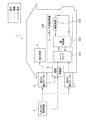
- FIG. 1 is a diagram illustrating a heat pump heating system according to the first embodiment.
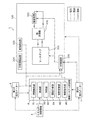
- FIG. 2 is a detailed configuration diagram of the heat pump heating device and the heating system control unit according to the first embodiment.
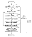
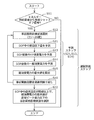
- FIG. 3 is a flowchart of a process for creating an operation plan of the heat pump heating device according to the first embodiment.
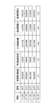
- FIG. 4A is a table showing an example of a prediction result of power consumption when the prior heat storage target room temperature is 24 ° C.
- FIG. 4B is a table showing a calculation result of the maximum value of the total power consumption for each prior heat storage target room temperature.
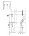
- FIG. 5A is a graph showing changes in HP output heat amount and room temperature for each prior heat storage target room temperature.
- FIG. 5B is a graph showing a transition of power consumption for each prior heat storage target room temperature.
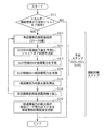
- FIG. 6 is a flowchart of a process for creating an operation plan of the heat pump heating device according to the second embodiment.
- FIG. 7 is a table showing the calculation result of the maximum value of the total power consumption for each prior heat storage target room temperature.
- FIG. 8 is a flowchart of processing for creating an operation plan of the heat pump heating device according to the third embodiment.
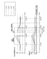
- FIG. 9A is a graph showing changes in HP output heat amount and room temperature for each prior heat storage target room temperature.
- FIG. 9B is a graph showing a transition of power consumption for each prior heat storage target room temperature.
- FIG. 10 is a table showing the calculation result of the maximum value of the total power consumption for each prior heat storage target room temperature.
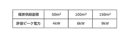
- FIG. 11 is a table showing an example of allowable peak power that varies depending on the floor area.
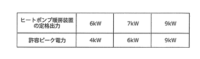
- FIG. 12 is a table showing an example of allowable peak power that varies according to the rated
- the heating system receives power supply from a power supply source and maintains the target temperature in a predetermined temperature range including a preset temperature.
- a heat pump unit that generates heat using electric power supplied from the power supply source
- a heat radiating unit that radiates heat generated by the heat pump unit
- a predetermined heat pump unit In order to stop the heat generation in the shut-off time zone and to maintain the target at the set temperature, the SOP heat amount, which is the heat amount to be radiated from the heat radiating section in the shut-off time zone, is set before and after the shut-off time zone.
- a heating system control unit that accumulates and heats the heat pump unit during the time period.
- the said heating system control part is the time before and behind the said shut-off time slot
- zone may be below an allowable peak electric power. Distribute it to the belt and heat it.
- the amount of SOP heat that should be radiated during the shut-off time zone is distributed to the time zones before and after it to generate heat, thereby suppressing power consumption peaks in the time zones before and after the shut-off time zone. You can get a heating system.
- the heating system control unit is distributed with the transition of the raw heat consumption consumed by the heat pump unit to maintain the target at the set temperature in each of the time zones before and after the shut-off time zone.
- the SOP is set so that the maximum value of the total power consumption, which is the sum of the general power consumption, the raw heat power consumption, and the product power consumption, is less than or equal to the allowable peak power.
- the upper power consumption in the time zone before the shut-off time zone is to increase the target temperature to a pre-heat storage target temperature higher than the set temperature at the start time of the shut-off time zone. It may be power consumption consumed by the heat pump unit. Similarly, the upper power consumption in the time zone after the shut-off time zone is consumed by the heat pump unit in order to raise the target temperature at the end time of the shut-off time zone to the set temperature. It may be power consumption. Furthermore, the said heating system control part may be provided with the detection part which detects object temperature and external temperature. And the said prediction part may predict the transition of the said upper-layer power consumption of each time slot
- the operation planning unit may include the shut-off among a plurality of the pre-heat storage target temperatures at which the maximum value of the total power consumption in each of the time zones before and after the shut-off time zone is less than or equal to the allowable peak power. You may select the said prior heat storage target temperature from which the maximum value of the said total power consumption through the time slot
- the operation planning unit may include the shut-off among a plurality of the pre-heat storage target temperatures at which the maximum value of the total power consumption in each of the time zones before and after the shut-off time zone is less than or equal to the allowable peak power.
- You may select the said prior heat storage target temperature from which the minimum temperature of the object in a time slot
- the prediction unit may predict a shut-off time, which is a time during which the target temperature decreases from the preliminary heat storage target temperature to the threshold temperature, for each of the plurality of preliminary heat storage target temperatures.
- the heating system control unit distributes to the time zone after the shut-off time zone at a timing when the shut-off time corresponding to the pre-heat storage target temperature selected from the start of the shut-off time zone has elapsed.
- heat amount which carried out may be piled up on the said heat pump part, and you may make it heat. Thereby, a user's comfort can be maintained further.
- the operation planning unit may select the pre-heat storage target temperature that can maximize the shut-off time among the plurality of pre-heat storage target temperatures.
- the operation planning unit creates the operation plan at a timing at which a signal including information specifying the shut-off time zone is received from the power supply source a predetermined time before the start of the shut-off time zone. May be executed.
- the signal may include information indicating the allowable peak power.
- the heating system control unit may accept an input of the allowable peak power from a user.
- the allowable peak power may be set based on the heat insulation performance of the building where the heating system is installed.
- the allowable peak power in the time zone before the shutdown time zone may be individually set so as to be larger than the allowable peak power in the time zone after the shutdown time zone.
- the predicted value of the total power consumption in the time zone before the shut-off time zone may have a higher prediction error than the predicted value of the total power consumption in the time zone before the shut-off time zone. Therefore, the power consumption peak can be more reliably suppressed by setting the allowable peak power in the time zone after the shut-off time zone to be relatively small.
- the heating system includes a heating device including the heat pump unit, the heat dissipation unit, and an HP control unit that controls the heat pump unit in accordance with an instruction from the heating system control unit, and the heating device is separate from the heating device.
- the heating system controller configured as described above may be provided.
- the heating device not only the heating device but also other devices can be controlled by the heating system control unit. Further, when used in an environment where control for shutoff is not required, it is sufficient to install only a heating device.
- a method for controlling a heating system is a method for controlling a heating system that receives supply of electric power from a power supply source and maintains a target temperature in a predetermined temperature range including a predetermined set temperature. It is.
- the heating system includes a heat pump unit that generates heat using electric power supplied from the power supply source, and a heat radiating unit that radiates heat generated by the heat pump unit.
- the heat pump unit stops heat generation in a predetermined shut-off time zone, and heat is radiated from the heat radiating unit in the shut-off time zone in order to maintain the target at the set temperature.
- the SOP heat amount is set to a time before and after the shut-off time zone so that the maximum power consumption in each time zone before and after the shut-off time zone is less than or equal to the allowable peak power. Distribute it to the belt and heat it.
- the heating system control step is distributed with the transition of the heat consumption power consumed by the heat pump unit in order to maintain the target at the set temperature in each of the time zones before and after the shut-off time zone.
- An operation plan step for creating an operation plan for distributing heat to generate heat may be included. In the heating system control step, the heat pump may be controlled based on the operation plan created in the operation plan step.
- the upper power consumption in the time zone before the shut-off time zone is to increase the target temperature to a pre-heat storage target temperature higher than the set temperature at the start time of the shut-off time zone. It may be power consumption consumed by the heat pump unit. Similarly, the upper power consumption in the time zone after the shut-off time zone is consumed by the heat pump unit in order to raise the target temperature at the end time of the shut-off time zone to the set temperature. It may be power consumption. Furthermore, the heating system control step may include a detection step of detecting a target temperature and an outside air temperature. In the prediction step, transition of the upper power consumption in each time zone before and after the shut-off time zone may be predicted based on the detection result in the detection step.
- a shut-off time that is a time during which the target temperature decreases from the preliminary heat storage target temperature to the threshold temperature may be predicted for each of the plurality of preliminary heat storage target temperatures.
- distribution is made to a time zone after the shut-off time zone at a timing when the shut-off time corresponding to the pre-heat storage target temperature selected from the start of the shut-off time zone has elapsed.
- heat amount which carried out may be piled up on the said heat pump part, and you may make it heat.
- the pre-heat storage target temperature that can maximize the shut-off time may be selected from the plurality of pre-heat storage target temperatures.
- FIG. 1 is a diagram showing a heat pump heating system 1 according to Embodiment 1 of the present invention.
- power is supplied from an energy supplier (power supply source) 4 to a house (building) through first and second power systems.
- the first power system is a power system to which power is stably supplied.
- the first power system is a power system having a relatively high power rate, and the power consumption is measured by the first power meter 6.
- the second electric power system is an electric power system that can be stopped by the energy supplier 4 at an arbitrary time zone.
- the second power system is a power system whose power rate is lower than that of the first power system, and the power consumption is measured by the second power meter 7.
- the heat pump heating device 100 includes at least a heat pump (raw heat unit) 101, a heat exchanger 102, and a heating device (heat radiating unit) 103.
- the heat pump heating device 100 dissipates the heat generated by the heat pump 101 from the heating device 103 through the heat exchanger 102, whereby the room temperature of the room in which the heating device 103 is installed includes a predetermined set temperature. It is the apparatus which maintains in the temperature range.
- the predetermined temperature range is, for example, a range in which the prior heat storage target room temperature (described later) is the upper limit and the threshold temperature (described later) is the lower limit.
- 1st electric power meter 6 measures the power consumption of apparatuses (namely, electric power load 5) other than the heating system control part 8 and the heat pump type heating apparatus 100.
- the heating system control unit 8 and the power load 5 operate by receiving power supply from the energy supplier 4 through the first power system.
- the 2nd electric power meter 7 measures the electric power consumption of the component of the heat pump type heating apparatus 100, such as a compressor, a pump, a fan (not shown). That is, each component of the heat pump heating device 100 operates by receiving power supply from the energy supplier 4 through the second power system.
- the heating system control unit 8 has a function of communicating with the energy supplier 4 and gives a control command to the heat pump heating device 100. For example, the heating system control unit 8 causes the heat pump heating device 100 to stop the raw heat during the shut-off time period. Further, the heating system control unit 8 causes the heat pump heating device 100 to operate based on an operation plan created in advance in a time zone before and after the shut-off time zone.
- the energy supplier 4 is a company that supplies electric power and gas to each household, and when it is desired to suppress the use of electric power in each household, through a shut-off signal in advance (hereinafter referred to as “pre-shut off signal”). Notify each home.
- the notification time of the prior shut-off signal is, for example, two hours before the time zone in which the use of power in each household is desired to be suppressed.
- FIG. 2 is a detailed configuration diagram of heat pump heating device 100 and heating system control unit 8 according to Embodiment 1 of the present invention.
- the heat pump 101 is an air heat source heat pump and compresses a refrigerant (for example, R410A) to a high temperature and high pressure state.
- the heat exchanger 102 includes a refrigerant that has been heated to a high temperature and a high pressure by the heat pump 101, and a secondary water cycle that is filled with water (that is, water that circulates between the heat exchanger 102 and the heating device 103). Heat exchange between them.
- the heating device 103 is a device for heating the home, and is, for example, a radiator or floor heating that releases thermal energy into the room through a heat dissipation panel.
- the specific example of the heating apparatus 103 is not limited to these, All apparatuses which have a thermal radiation part which discharge
- the outside air temperature detection unit 104 is installed outside the room and detects the outside air temperature with a thermostat or the like.
- the room temperature detector 105 is installed indoors and detects the temperature of the room with a thermostat or the like.
- the room temperature detection unit 105 is an example of a temperature detection unit that measures the temperature of an object (in this case, the room), and is not limited to this.
- a temperature detection unit that detects the temperature of the floor (target) may be used instead of the room temperature detection unit 105.
- the HP control unit 106 controls the amount of heat released from the heating device 103 and the amount of raw heat from the heat pump 101 so that the room temperature of the room in which the heating device 103 is installed is maintained within a predetermined range including the set temperature. To do. Note that the HP control unit 106 controls the operations of the heat pump 101 and the heating device 103 according to, for example, operating conditions set by the user in a normal state (a state in which the pre-shutoff signal is not received). On the other hand, the HP control unit 106 controls the operations of the heat pump 101 and the heating device 103 in accordance with instructions from the heating system control unit 8 in the time zones before and after the shut-off time zone.
- the heating system control unit 8 includes a state detection unit 81, a communication unit 82, a prediction unit 83, an operation planning unit 84, a control switching unit 85, a control command unit 86, and the like.
- the heating system control unit 8 is configured separately from the heat pump heating device 100.
- the heat pump heating device 100 and the heating system control unit 8 may be configured as an integral unit, for example, the heating system control unit 8 may be disposed at the position of the HP control unit 106.
- the state detection unit 81 includes an amount of heat released from the heating device 103 to each room from various signals detected by the outside air temperature detection unit 104 and the room temperature detection unit 105, and the first and second power meters 6 and 7. Various information such as the measured power consumption is detected (collected).
- the communication unit 82 receives the pre-shutoff signal and the on signal from the energy supplier 4 and informs the energy supplier 4 that the supply of power to the heat pump heating device 100 through the second power system is cut off or resumed. It has a function to notify The pre-shutoff signal received by the communication unit 82 is a signal indicating that the supply of power through the second power system is stopped after a predetermined time has elapsed.
- This pre-shutoff signal includes information for specifying a “shutoff time zone”, which is a time zone in which power supply through at least the second power system is stopped.
- a “shutoff time zone” is a time zone in which power supply through at least the second power system is stopped.
- the shut-off time zone in the example described below is one hour from 18:00 to 19:00.
- the prior shut-off signal may include information indicating an allowable peak power in a time zone before and after the shut-off time zone.
- the allowable peak power in the example described below is 4.5 kW.
- the prediction unit 83 calculates the amount of heat necessary for heating in the shut-off time zone, and the time zones before and after the shut-off time zone. And an algorithm for predicting the transition of the amount of room temperature decrease in the shut-off time zone. A specific prediction method will be described later.
- the operation planning unit 84 is, for example, a time zone before and after the shut-off time zone based on the predicted value predicted by the prediction unit 83 at the timing when the communication unit 82 receives the pre-shutoff signal from the energy supplier 4.
- the operation plan of the heat pump type heating device 100 is made.
- the control switching unit 85 gives priority to the independent control by the HP control unit 106 in the heat pump heating device 100 when the communication unit 82 has not received a pre-shutoff signal from the energy supplier 4.
- the operation plan unit 84 creates and makes the HP control unit 106 control each component described above according to the operation plan notified from the control command unit 86.
- the control command unit 86 transmits the operation plan set by the operation plan unit 84 to the HP control unit 106 of the heat pump heating device 100.
- FIG. 3 is a flowchart of a process for creating an operation plan of the heat pump heating device 100 performed by the operation planning unit 84 and the prediction unit 83 according to Embodiment 1 of the present invention.
- FIG. 4A is a table showing an example of a prediction result of power consumption when the prior heat storage target room temperature is 24 ° C.
- FIG. 4B is a table showing a calculation result of the maximum value of the total power consumption for each prior heat storage target room temperature.
- FIG. 5A is a graph showing changes in HP output heat amount and room temperature for each prior heat storage target room temperature predicted by the prediction unit 83.
- FIG. 5B is a graph showing the transition of power consumption for each prior heat storage target room temperature predicted by the prediction unit 83.
- the amount of heat to be radiated from the heating device 103 in the shut-off time zone (hereinafter referred to as “SOP heat amount”) in order to maintain the room temperature at the set temperature is referred to as the shut-off time zone.
- SOP heat amount the amount of heat to be radiated from the heating device 103 in the shut-off time zone
- This is an operation plan for adding heat to the heat pump 101 and generating heat in the time zones before and after (hereinafter, referred to as “preliminary accumulation period” and “post-accumulation period”). More specifically, the operation planning unit 84 determines the SOP heat amount so that the maximum power consumption in each of the preliminary product period and the post product period is equal to or less than the allowable peak power. Create an operation plan to distribute and heat up the period.
- the operation plan unit 84 starts creating an operation plan at the timing when the communication unit 82 receives the pre-shutoff signal from the energy supplier 4 (YES in S11).
- the timing of the operation plan creation is not limited to this, and may be started at a predetermined time (for example, midnight), for example. However, in this case, it is necessary to know the shut-off time zone of the day.
- the operation planning unit 84 selects a pre-heat storage target room temperature (pre-heat storage target temperature) (S12).
- This pre-heat storage target room temperature is the room temperature at the start of the shut-off time zone.
- the example of FIG. 3 shows a case where the selection is made in increments of 1 degree from the range of 21 degrees to 24 degrees.
- the prediction unit 83 uses the power consumption consumed by the heat pump 101 (hereinafter referred to as “HP power consumption”) in each of the prior accumulation period and the subsequent accumulation period from the outside air temperature and room temperature information detected by the state detection unit 81. ”Is predicted (S13). This predicted value depends on the capacity of the heat pump (rated output, COP), the capacity of the heating device 103, and the house performance (such as heat dissipation loss).
- the HP power consumption predicted in step S13 is the heat consumption power consumed by the heat pump 101 in order to maintain the room at the set temperature in each of the pre-product period and the subsequent product period (in FIG. 4A). Power required to generate the amount of heat corresponding to the amount of heat maintained at room temperature) and the amount of power consumed for heating the distributed SOP heat amount by the heat pump 101 (the amount of heat corresponding to the amount of room temperature heating in FIG. 4A). And the time change of the total value).
- the prediction unit 83 predicts the transition of general power consumption (S14).
- the general power consumption estimated in step S14 is a time change of the power consumed by apparatuses (in the example of FIG. 1, electric power load 5) other than the heat pump heating device 100.
- the operation planning unit 84 calculates the maximum value of the total power consumption in each of the prior product period and the subsequent product period based on these predicted values (S15). Note that the total power consumption calculated in step S15 is a change over time in the total value of the raw heat power consumption, the accumulated power consumption, and the general power consumption predicted in steps S13 to S14.
- FIG. 4A shows numerical changes in time, room temperature (° C.), room temperature maintenance heat (W), room temperature heating heat (W), HP power consumption (W), general power consumption (W), and total power consumption (W).
- FIG. 4A shows numerical changes in time, room temperature (° C.), room temperature maintenance heat (W), room temperature heating heat (W), HP power consumption (W), general power consumption (W), and total power consumption (W).
- the room temperature at 17:00 is the set temperature of 20 ° C.
- the temperature of the heat pump heating device 100 is set so that the room temperature becomes this temperature (20 ° C.) except for the three periods of the advance accumulation period, the shut-off period, and the subsequent accumulation period. Then, the room temperature starts to rise gradually from 17:00, and the room temperature rises to 21 ° C. at 17:15, 15 minutes later. Similarly, the temperature reaches 22 ° C. at 17:30, 23 ° C. at 17:45, and reaches the target preliminary heat storage target temperature of 24 ° C. at 18:00. That is, FIG.
- 4A shows the room temperature from the set temperature (20 ° C.) to the pre-heat storage target room temperature (24 ° C.) at a rate of 1 ° C. every 15 minutes during 1 hour (preliminary overlay period) from 17:00 to 18:00. An example of raising is shown.
- the amount of heat required to raise the room temperature from 20 ° C. to 21 ° C. in 15 minutes from 17:00 to 17:15 is the “room temperature maintaining heat amount” necessary to maintain the room temperature at 20 ° C. This is the sum of the "heat amount at room temperature” required to increase the temperature.
- the room temperature maintenance calorie can be calculated by Equation 1
- Room temperature maintenance heat amount (room temperature-outside air temperature) x heat insulation performance x room surface area (1)
- Room temperature heating amount temperature change amount ⁇ specific air heat ⁇ room volume / heating time (Equation 2)
- the HP power consumption can be calculated by Equation 3 as the HP power consumption consumed by the heat pump 101 to regenerate the room temperature heating heat and the room temperature maintenance heat. That is, the HP power consumption for 15 minutes from 17:00 to 17:15 is 2249 W.
- HP power consumption (room temperature heating amount + room temperature maintaining amount) / COP (Equation 3)
- the general power consumption which is the power consumption of home appliances (power load 5), consumed from 17 o'clock to 15:15 at 17:15 is 1640W.
- the prediction method of general power consumption is not specifically limited, For example, what is necessary is just to predict based on the track record of the past power consumption.
- the power consumption measured by the first power meter 6 is periodically collected and accumulated by the state detection unit 81. Then, the average value of past power consumption results (for example, three results of one week ago, two weeks ago, and three weeks ago) on the same day of the week as the time zone to be predicted and the same time is used as the predicted value. That's fine.
- the total power consumption from 17:15 to 17:30 for 15 minutes is 3909 W
- the total power consumption from 17:30 to 17:45 is 3769 W
- the total power consumption from 17:45 to 18:15 is 15 minutes.
- the total power consumption is 4000W.
- the maximum value of the total power consumption in the prior product period from 17:00 to 18:00 is 4000 W (4 kW).
- the transition of total power consumption during the subsequent period can be calculated.
- it corresponds to the sum of “room temperature maintenance heat amount” required to maintain the room temperature at the end of the shut-off time period and “room temperature heating energy” required to raise the room temperature to the set temperature.
- the power consumed by the heat pump 101 in order to generate the amount of heat is defined as HP power consumption.
- the room temperature at the end of the shut-off period is 18 ° C. and the room temperature is increased over 30 minutes by 1 ° C. every 15 minutes to the set temperature of 20 ° C.
- the room temperature maintenance heat amount and the room temperature heating heat amount every 15 minutes are calculated using Equation 2, and the maximum value of the total power consumption can be calculated using these.
- the prior overlay period is 1 hour and the subsequent overlay period is 30 minutes, but this time can be arbitrarily changed.
- the longer the time the smaller the peak of power consumption, but the heat dissipation loss increases and the power consumption increases.
- the shorter the time the smaller the heat dissipation loss, but the higher the power consumption peak.
- the time is too short, a rapid temperature change occurs, which impairs user comfort.
- the length of the overlay period may be changed according to the temperature change amount. That is, the higher the pre-heat storage target room temperature, the longer the prior overlay period, and the greater the difference between the predicted value of the room temperature at the end of the shut-off time zone and the set temperature, the longer the subsequent overlay period. By doing so, it is possible to avoid increasing the peak of power consumption without impairing the comfort of the user.
- the operation planning unit 84 stores the maximum value of the total power consumption calculated in step S15 for each selected prior heat storage target room temperature, and repeats a series of operations (S12 to S15) (S16). As a result, as shown in FIG. 4B, for example, a list of maximum values of total power consumption for each prior heat storage target room temperature is obtained. Note that the “maximum value of total power consumption” in the rightmost column of FIG. 4B indicates the maximum value of total power consumption throughout the prior product period and the subsequent product period.
- the operation planning unit 84 selects a prior heat storage target room temperature at which the maximum value of the total power consumption is equal to or less than the allowable peak power (S17). For example, assuming that the allowable peak power is 4.5 kW, the maximum value of the total power consumption is 23 ° C. and 24 ° C. among the prior heat storage target room temperatures shown in FIG. 4B. And the operation plan part 84 in Embodiment 1 selects 24 degreeC with the smallest maximum value of total power consumption.
- control command unit 86 HP operates the operation plan for the prior product period and the subsequent product period created by the operation plan unit 84 (for example, the table in FIG. 4A corresponds to the operation plan for the prior product period). Notify the control unit 106. Then, the HP control unit 106 controls the operation of the heat pump 101 according to the acquired operation plan.
- the HP control unit 106 determines that the room temperature of the room in which the heating device 103 is installed is 1 hour from 15 o'clock to 18 o'clock, which is a prior product period, and 1 ° C. every 15 minutes for a total of 4 ° C.
- the operation of the heat pump 101 and the heating device 103 is controlled so as to rise. That is, in this one hour, the preset temperature is changed from 20 ° C. to 24 ° C., which is the pre-heat storage target room temperature.
- the HP controller 106 increases the room temperature of the room in which the heating device 103 is installed by 2 ° C. in 1 minute increments every 15 minutes from 19 o'clock 30 minutes, 19 o'clock, which is the subsequent product period.
- the operation of the heat pump 101 and the heating device 103 is controlled. That is, in this 30 minutes, the room temperature is restored from 18 ° C. at the end of the shut-off period to 20 ° C. which is the set temperature.
- the HP output heat amount, the room temperature, and the total power consumption change according to the prediction results shown in FIGS. 5A and 5B.
- the HP output heat amount, the room temperature, and the total power consumption monotonously increase so that the room temperature at the end of the prior overlay period reaches the prior heat storage target room temperature.
- the HP output heat amount becomes 0 (that is, the heat pump 101 is stopped), the room temperature monotonously decreases, and the power consumption is only the general power consumption.
- the HP output heat amount, the room temperature, and the total power consumption monotonically increase so that the room temperature at the end of the subsequent accumulation period reaches the set temperature.
- the transition of HP output heat quantity, room temperature, and total power consumption shows the same tendency regardless of which pre-heat storage target room temperature is selected, but as the pre-heat storage target room temperature becomes higher as shown in FIGS. 5A and 5B.
- the temperature that should be raised during the prior accumulation period is increased, the HP output heat amount is increased, and the HP power consumption is increased.
- the heat pump 101 stops in the shut-off time period, and the heat radiation from the heating device 103 is interrupted, so that the room temperature decreases.
- the room temperature at the end of the shut-off time zone becomes higher as the prior heat storage target room temperature is higher.
- the higher the pre-heat storage target room temperature the smaller the HP output heat amount and HP power consumption for returning the room temperature to the set temperature during the subsequent accumulation period.
- the maximum value of the total power consumption in the time zones before and after the shut-off time zone can be leveled below the allowable peak power.
- Embodiment 1 the transition of the total power consumption is predicted for each prior heat storage target room temperature, and the prior heat storage target room temperature that allows the maximum value of the total power consumption to be equal to or less than the allowable peak power is selected.
- the room temperature is greatly lowered due to heat radiation during the shut-off time period, and the comfort of the user of the heat pump heating device 100 is impaired.
- the transition of the room temperature decrease amount in the shut-off time zone is further predicted, and the maximum value of the total power consumption is set while maintaining the room temperature that does not impair the comfort of the user of the heat pump heating device 100. Take a method that falls within the allowable peak power.
- FIG. 6 is a flowchart of a process for creating an operation plan of the heat pump heating device 100 performed by the operation planning unit 84 and the prediction unit 83 according to Embodiment 2 of the present invention.
- FIG. 7 is a table showing the calculation result of the maximum value of the total power consumption for each prior heat storage target room temperature.
- Steps S12, S13, S14, S15, and S16 in FIG. 6 perform the same functions as those in the first embodiment (FIG. 3).
- the operation planning unit 84 has a plurality of prior heat storage targets in which the maximum value of the total power consumption is equal to or less than the allowable peak power as shown in FIG. Of room temperature (23 ° C., 24 ° C., 25 ° C.), 25 ° C. at which the lowest room temperature in the shut-off time zone is not less than the allowable room temperature is selected.
- the prior heat storage target with the smallest total power consumption is the smallest. Room temperature may be selected.
- the maximum value of power consumption does not exceed the allowable peak power, and A pre-heat storage target room temperature that does not fall below an allowable room temperature can be selected.
- the maximum value of the power consumption in the time zone before and after the shut-off time zone can be leveled below the allowable peak power while maintaining a room temperature that does not impair the comfort of the user of the heat pump heating device 100.
- Embodiment 3 Since the configuration of the heat pump heating system 1 according to Embodiment 3 is the same as that of Embodiment 1, description thereof is omitted. Further, detailed description of points common to the first and second embodiments will be omitted, and the description will be focused on the differences.
- the pre-heat storage target room temperature that minimizes the maximum power consumption is selected within a range that does not fall below the allowable room temperature.
- the optimal control is not necessarily performed.
- Embodiment 3 the transition of the room temperature decrease amount in the shut-off time zone is predicted for each prior heat storage target room temperature, and the shut-off time that does not impair the comfort of the user of the heat pump heating device 100 is determined. Then, the maximum value of the total power consumption is compared.
- FIG. 8 is a flowchart of a process for creating an operation plan of the heat pump heating device 100 performed by the operation planning unit 84 and the prediction unit 83 according to Embodiment 3 of the present invention.
- FIG. 9A is a graph showing the HP output heat amount and room temperature transition predicted by the prediction unit 83 for each prior heat storage target room temperature.
- FIG. 9B is a graph showing the transition of power consumption for each prior heat storage target room temperature predicted by the prediction unit 83.
- FIG. 10 is a table showing the calculation result of the maximum value of the total power consumption for each prior heat storage target room temperature.
- steps S12, S13, S14, S15, and S16 in FIG. 8 perform the same functions as those in the first embodiment (FIG. 3).
- the heat pump heating system according to Embodiment 3 can restart the power supply to the heat pump 101 before the shut-off time period indicated by the prior shut-off signal ends.
- the heat pump 101 operates by receiving power supply from the energy supplier 4 through the first system until the original end time of the shut-off time zone.
- the prediction unit 83 predicts the transition of the room temperature decrease amount in the shut-off time zone, and determines the shut-off time.
- the shut-off time is a time during which the room temperature decreases from the pre-heat storage target temperature to the threshold temperature (allowable room temperature), and can be rephrased as the time during which the power supply to the heat pump 101 is actually stopped. .
- step S32 the operation planning unit 84 selects a pre-heat storage target temperature in consideration of the shut-off time from among a plurality of pre-heat storage target temperatures whose maximum total power consumption is equal to or less than the allowable peak power.
- the operation plan unit 84 may determine the prior heat storage target room temperature in consideration of the balance between the maximum value of the total power consumption and the reduction width of the shut-off time zone. For example, when the allowable room temperature is 18 ° C. and the allowable peak power is 4.5 kW, the operation planning unit 84 has a plurality of prior heat storage targets in which the maximum value of the total power consumption is equal to or lower than the allowable peak power as shown in FIG. Of room temperature (21 ° C., 22 ° C., 23 ° C., 24 ° C., 25 ° C., 26 ° C.), 23 ° C. having the smallest total power consumption may be selected.
- the selection method of the prior heat storage target room temperature is not limited to this, and the operation planning unit 84 selects 25 ° C. that can maximize the shut-off time among a plurality of prior heat storage target room temperatures that satisfy the allowable peak power condition. You may do it.
- the heating system control part 8 makes the heat pump 101 restart a raw heat before the original shut-off time slot
- the heating system control unit 8 uses the heat pump 101 to calculate the amount of SOP heat distributed in the subsequent product period at the timing when the shut-off time corresponding to the pre-heat storage target temperature selected from the start of the shut-off time zone has elapsed. Overheat and heat up. That is, as shown in FIG. 9A and FIG. 9B, the end time of the shut-off time zone and the start and end times of the subsequent overlay period in Embodiment 3 vary depending on the selected pre-heat storage target room temperature.
- the transition of the room temperature decrease amount and the total power consumption is predicted for each prior heat storage target room temperature, and the shut-off time that does not fall below the allowable room temperature is predicted.
- the maximum value of the total power consumption in the time zones before and after the shut-off time zone can be leveled below the allowable peak power while maintaining the room temperature that does not impair the comfort of the user of the device 100.
- Embodiments 1, 2, and 3 the description has been made on the assumption that the allowable peak power is notified from the energy supplier 4, but it may be set by the following method.
- the user may register / set allowable peak power in the heating system control unit 8 for each house.
- FIG. 11 is a diagram showing the correspondence between the heating supply area and the allowable peak power. If the room has a heating supply area of 50 m 2, the allowable peak power is set to 4 kW. In this way, the allowable peak power may be set according to the floor area to which heating is supplied.
- FIG. 12 is a diagram showing the correspondence between the rated output of the heat pump heater and the allowable peak power. If the rated output is 6 kW, the allowable peak power is set to 4 kW. As described above, a method of setting the allowable peak power according to the rated output of the heat pump heating device 100 may be taken.
- the energy supplier 4 may include the list of allowable peak power corresponding to the floor area as shown in FIG. 11 in the pre-shutoff signal and transmit it to the heating system control unit 8. Then, the heating system control unit 8 acquires the floor area of the room in which the heating device 103 is installed, and selects the allowable peak power corresponding to the acquired floor area from the list included in the pre-shutoff signal. May be.
- the energy supplier 4 may include the list of allowable peak power corresponding to the rated output as shown in FIG. 12 in the pre-shutoff signal and transmit it to the heating system control unit 8.
- the heating system control part 8 may acquire the rated output of the heat pump type heating apparatus 100, and may make it select the allowable peak electric power corresponding to the acquired rated output from the list
- the optimum allowable peak power is predicted from the outside air temperature and the current room temperature information, and is set in the heating system control unit 8. You may make it do. Accordingly, it is possible to set an appropriate allowable peak power based on environmental information such as the outside temperature and room temperature information at the start of the shut-off time period. Thereby, leveling of power consumption can be realized within the allowable room temperature range where comfort can be maintained.
- the allowable peak power is treated as a fixed value in time, that is, through the prior product period and the subsequent product period, but may be varied with time as follows.
- the permissible peak power during the posterior product period may be set individually so as to be smaller than the permissible peak power during the prior product period. This is because when the forecast error of household power demand and heating load is taken into consideration, the predicted value of total power consumption during the subsequent product period may be larger than the predicted value of total power consumption during the previous product period. Is expensive. Therefore, by estimating the allowable peak power during the subsequent product period to be smaller, it is possible to reduce the amount of increase in peak power due to the deviation between the predicted value of peak power and the actual value.
- Each of the above devices is specifically a computer system including a microprocessor, ROM, RAM, a hard disk unit, a display unit, a keyboard, a mouse, and the like.
- a computer program is stored in the RAM or the hard disk unit.
- Each device achieves its functions by the microprocessor operating according to the computer program.
- the computer program is configured by combining a plurality of instruction codes indicating instructions for the computer in order to achieve a predetermined function.
- the system LSI is a super multifunctional LSI manufactured by integrating a plurality of components on a single chip, and specifically, a computer system including a microprocessor, a ROM, a RAM, and the like. .
- a computer program is stored in the RAM.
- the system LSI achieves its functions by the microprocessor operating according to the computer program.
- the constituent elements constituting each of the above devices may be constituted by an IC card or a single module that can be attached to and detached from each device.
- the IC card or module is a computer system that includes a microprocessor, ROM, RAM, and the like.
- the IC card or the module may include the super multifunctional LSI described above.
- the IC card or the module achieves its functions by the microprocessor operating according to the computer program. This IC card or this module may have tamper resistance.
- the present invention may be the method described above. Further, the present invention may be a computer program that realizes these methods by a computer, or may be a digital signal composed of a computer program.
- the present invention also relates to a computer-readable recording medium capable of reading a computer program or a digital signal, such as a flexible disk, hard disk, CD-ROM, MO, DVD, DVD-ROM, DVD-RAM, BD (Blu-ray Disc), It may be recorded in a semiconductor memory or the like. Further, it may be a digital signal recorded on these recording media.
- a computer-readable recording medium capable of reading a computer program or a digital signal, such as a flexible disk, hard disk, CD-ROM, MO, DVD, DVD-ROM, DVD-RAM, BD (Blu-ray Disc), It may be recorded in a semiconductor memory or the like. Further, it may be a digital signal recorded on these recording media.
- the present invention may transmit a computer program or a digital signal via an electric communication line, a wireless or wired communication line, a network represented by the Internet, a data broadcast, or the like.
- the present invention may be a computer system including a microprocessor and a memory.
- the memory may store the computer program, and the microprocessor may operate according to the computer program.
- program or digital signal may be recorded on a recording medium and transferred, or the program or digital signal may be transferred via a network or the like, and may be implemented by another independent computer system.
- the heat pump heating system and the control method thereof according to the present invention are useful as a heating system that contributes to stabilization of system power.
Abstract
L'invention porte sur un système de chauffage du type pompe à chaleur (1), lequel système comprend une pompe à chaleur (101) qui produit de la chaleur par utilisation d'une énergie électrique fournie à partir d'un fournisseur d'énergie (4), un dispositif chauffant (103) qui rayonne de la chaleur produite par la pompe à chaleur (101) sous la forme d'un sujet, et une unité de commande de système chauffant (8) qui permet à la pompe à chaleur (101) d'arrêter de produire de la chaleur pendant une période de temps d'interruption, et qui ajoute une quantité de chaleur SOP, qui est une quantité de chaleur devant être rayonnée à partir du dispositif chauffant (103) dans la période de temps d'interruption afin de maintenir le sujet à une température pré-établie, à la pompe à chaleur (101), dans des périodes de temps avant et après la période de temps d'interruption, puis qui permet à la pompe à chaleur (101) de produire de la chaleur, l'unité de commande de système chauffant (8) permettant à la pompe à chaleur (101) de produire de la chaleur par distribution de la quantité de chaleur SOP dans les périodes de temps avant et après la période de temps d'interruption, de sorte que les deux valeurs maximales de consommation d'énergie dans les périodes de temps respectives avant et après la période de temps d'interruption ne soient pas supérieures à un pic de puissance électrique admissible.
Priority Applications (2)
| Application Number | Priority Date | Filing Date | Title |
|---|---|---|---|
| EP12748144.8A EP2541155B1 (fr) | 2011-04-26 | 2012-04-18 | Système de chauffage, et procédé de commande de système de chauffage |
| JP2012530002A JP5090580B1 (ja) | 2011-04-26 | 2012-04-18 | 暖房システム及び暖房システム制御方法 |
Applications Claiming Priority (2)
| Application Number | Priority Date | Filing Date | Title |
|---|---|---|---|
| JP2011098707 | 2011-04-26 | ||
| JP2011-098707 | 2011-04-26 |
Publications (1)
| Publication Number | Publication Date |
|---|---|
| WO2012147311A1 true WO2012147311A1 (fr) | 2012-11-01 |
Family
ID=47071844
Family Applications (1)
| Application Number | Title | Priority Date | Filing Date |
|---|---|---|---|
| PCT/JP2012/002700 WO2012147311A1 (fr) | 2011-04-26 | 2012-04-18 | Système de chauffage, et procédé de commande de système de chauffage |
Country Status (3)
| Country | Link |
|---|---|
| EP (1) | EP2541155B1 (fr) |
| JP (1) | JP5090580B1 (fr) |
| WO (1) | WO2012147311A1 (fr) |
Cited By (3)
| Publication number | Priority date | Publication date | Assignee | Title |
|---|---|---|---|---|
| JP2014214978A (ja) * | 2013-04-25 | 2014-11-17 | パナソニック株式会社 | ヒートポンプシステム制御装置、ヒートポンプシステム、および、ヒートポンプシステム制御方法 |
| US9487481B2 (en) | 2013-02-21 | 2016-11-08 | Bristol-Myers Squibb Company | Bicyclic compounds |
| CN109340904A (zh) * | 2018-11-12 | 2019-02-15 | 华北电力大学 | 电采暖协同优化运行方法 |
Families Citing this family (3)
| Publication number | Priority date | Publication date | Assignee | Title |
|---|---|---|---|---|
| US11226124B2 (en) | 2015-10-09 | 2022-01-18 | The Procter & Gamble Company | Systems and methods for coupling the operations of an air handling device and a volatile composition dispenser |
| CA3001492A1 (fr) * | 2015-10-09 | 2017-04-13 | The Procter & Gamble Company | Regulation de temperature par commande a distance d'un dispositif de traitement d'air et utilisation du capteur de temperature d'un distributeur de composition volatile sans fil |
| CN115164272B (zh) * | 2022-07-19 | 2023-08-29 | 吉林建筑大学 | 智能供暖处理方法及装置 |
Citations (4)
| Publication number | Priority date | Publication date | Assignee | Title |
|---|---|---|---|---|
| JPH06197450A (ja) * | 1992-12-21 | 1994-07-15 | Mitsubishi Electric Corp | デマンド制御装置及びデマンド制御システム |
| JP2005030705A (ja) * | 2003-07-08 | 2005-02-03 | Sunpot Co Ltd | 暖房装置 |
| JP2009204298A (ja) | 2008-02-01 | 2009-09-10 | Daikin Ind Ltd | 貯湯式熱源装置 |
| JP2009204299A (ja) | 2008-02-01 | 2009-09-10 | Daikin Ind Ltd | 貯湯式熱源装置 |
Family Cites Families (4)
| Publication number | Priority date | Publication date | Assignee | Title |
|---|---|---|---|---|
| US5462225A (en) * | 1994-02-04 | 1995-10-31 | Scientific-Atlanta, Inc. | Apparatus and method for controlling distribution of electrical energy to a space conditioning load |
| ES2119104T3 (es) * | 1994-06-17 | 1998-10-01 | Schlumberger Ind Sa | Metodo de controlar la temperatura en un edificio empleando la informacion relativa a los cambios de tarifa de suministro de energia para minimizar costes. |
| US6860431B2 (en) * | 2003-07-10 | 2005-03-01 | Tumkur S. Jayadev | Strategic-response control system for regulating air conditioners for economic operation |
| JP4631967B2 (ja) * | 2008-12-22 | 2011-02-16 | 株式会社デンソー | 蓄電蓄熱装置 |
-
2012
- 2012-04-18 JP JP2012530002A patent/JP5090580B1/ja not_active Expired - Fee Related
- 2012-04-18 EP EP12748144.8A patent/EP2541155B1/fr not_active Not-in-force
- 2012-04-18 WO PCT/JP2012/002700 patent/WO2012147311A1/fr active Application Filing
Patent Citations (4)
| Publication number | Priority date | Publication date | Assignee | Title |
|---|---|---|---|---|
| JPH06197450A (ja) * | 1992-12-21 | 1994-07-15 | Mitsubishi Electric Corp | デマンド制御装置及びデマンド制御システム |
| JP2005030705A (ja) * | 2003-07-08 | 2005-02-03 | Sunpot Co Ltd | 暖房装置 |
| JP2009204298A (ja) | 2008-02-01 | 2009-09-10 | Daikin Ind Ltd | 貯湯式熱源装置 |
| JP2009204299A (ja) | 2008-02-01 | 2009-09-10 | Daikin Ind Ltd | 貯湯式熱源装置 |
Non-Patent Citations (1)
| Title |
|---|
| See also references of EP2541155A4 |
Cited By (3)
| Publication number | Priority date | Publication date | Assignee | Title |
|---|---|---|---|---|
| US9487481B2 (en) | 2013-02-21 | 2016-11-08 | Bristol-Myers Squibb Company | Bicyclic compounds |
| JP2014214978A (ja) * | 2013-04-25 | 2014-11-17 | パナソニック株式会社 | ヒートポンプシステム制御装置、ヒートポンプシステム、および、ヒートポンプシステム制御方法 |
| CN109340904A (zh) * | 2018-11-12 | 2019-02-15 | 华北电力大学 | 电采暖协同优化运行方法 |
Also Published As
| Publication number | Publication date |
|---|---|
| JPWO2012147311A1 (ja) | 2014-07-28 |
| JP5090580B1 (ja) | 2012-12-05 |
| EP2541155A1 (fr) | 2013-01-02 |
| EP2541155B1 (fr) | 2016-02-24 |
| EP2541155A4 (fr) | 2015-01-14 |
Similar Documents
| Publication | Publication Date | Title |
|---|---|---|
| JP5090580B1 (ja) | 暖房システム及び暖房システム制御方法 | |
| JP5025834B2 (ja) | 運転計画方法、運転計画装置、ヒートポンプ式給湯システムの運転方法、及びヒートポンプ式給湯暖房システムの運転方法 | |
| US9851110B2 (en) | Heating system control method and heating system | |
| JP5121024B2 (ja) | 配電網応答型制御装置 | |
| US9494373B2 (en) | Heat pump operation method and heat pump system | |
| WO2012169115A1 (fr) | Procédé de fonctionnement pour pompe à chaleur, et système de pompe à chaleur | |
| JP6240900B2 (ja) | ヒートポンプ制御装置及びヒートポンプ制御装置の制御方法 | |
| JP5909684B2 (ja) | 暖房システム及び暖房システムの制御方法 | |
| EP2818801B1 (fr) | Procédé et dispositif permettant de commander des dispositifs de chauffage | |
| JP5820998B2 (ja) | 暖房システムの制御方法及び暖房システム | |
| JP5853162B2 (ja) | 暖房システム及び暖房システムの制御方法 | |
| JP5899484B2 (ja) | ヒートポンプ式暖房システムの制御方法及び暖房システム | |
| JP5938744B2 (ja) | ヒートポンプ式暖房システムの制御方法及び暖房システム |
Legal Events
| Date | Code | Title | Description |
|---|---|---|---|
| ENP | Entry into the national phase |
Ref document number: 2012530002 Country of ref document: JP Kind code of ref document: A |
|
| WWE | Wipo information: entry into national phase |
Ref document number: 2012748144 Country of ref document: EP |
|
| 121 | Ep: the epo has been informed by wipo that ep was designated in this application |
Ref document number: 12748144 Country of ref document: EP Kind code of ref document: A1 |
|
| NENP | Non-entry into the national phase |
Ref country code: DE |