WO2012147284A1 - 移動物体検出装置 - Google Patents
移動物体検出装置 Download PDFInfo
- Publication number
- WO2012147284A1 WO2012147284A1 PCT/JP2012/002396 JP2012002396W WO2012147284A1 WO 2012147284 A1 WO2012147284 A1 WO 2012147284A1 JP 2012002396 W JP2012002396 W JP 2012002396W WO 2012147284 A1 WO2012147284 A1 WO 2012147284A1
- Authority
- WO
- WIPO (PCT)
- Prior art keywords
- ultrasonic
- moving object
- phase difference
- receivers
- ultrasonic receivers
- Prior art date
- Legal status (The legal status is an assumption and is not a legal conclusion. Google has not performed a legal analysis and makes no representation as to the accuracy of the status listed.)
- Ceased
Links
Images



Classifications
-
- G—PHYSICS
- G01—MEASURING; TESTING
- G01S—RADIO DIRECTION-FINDING; RADIO NAVIGATION; DETERMINING DISTANCE OR VELOCITY BY USE OF RADIO WAVES; LOCATING OR PRESENCE-DETECTING BY USE OF THE REFLECTION OR RERADIATION OF RADIO WAVES; ANALOGOUS ARRANGEMENTS USING OTHER WAVES
- G01S7/00—Details of systems according to groups G01S13/00, G01S15/00, G01S17/00
- G01S7/52—Details of systems according to groups G01S13/00, G01S15/00, G01S17/00 of systems according to group G01S15/00
- G01S7/521—Constructional features
-
- G—PHYSICS
- G01—MEASURING; TESTING
- G01S—RADIO DIRECTION-FINDING; RADIO NAVIGATION; DETERMINING DISTANCE OR VELOCITY BY USE OF RADIO WAVES; LOCATING OR PRESENCE-DETECTING BY USE OF THE REFLECTION OR RERADIATION OF RADIO WAVES; ANALOGOUS ARRANGEMENTS USING OTHER WAVES
- G01S15/00—Systems using the reflection or reradiation of acoustic waves, e.g. sonar systems
- G01S15/02—Systems using the reflection or reradiation of acoustic waves, e.g. sonar systems using reflection of acoustic waves
- G01S15/06—Systems determining the position data of a target
- G01S15/42—Simultaneous measurement of distance and other co-ordinates
Definitions
- the present invention relates to a moving object detection apparatus that detects the position of a moving object using ultrasonic waves.
- Patent Document 1 discloses a vehicle position detection device that detects an angle between a position marker installed on a road surface and a host vehicle from a Doppler signal obtained from a reflected wave of transmitted radio waves (or ultrasonic waves). ing.
- This vehicle position detection device has a Doppler detection sensor mounted on the vehicle.
- the Doppler detection sensor transmits a radio wave having a frequency f 0 as a search wave to a position marker previously set on the road surface.
- the reflected wave of frequency fi received by the antenna is input to the mixer together with a part of the transmission signal and mixed.
- the relative speed extracting means calculates a relative speed V ′ with respect to the position marker from the following equation (1).
- fd 2 ⁇ f 0 ⁇ V ′ / c
- c is the speed of light (3 ⁇ 10 8 (m / sec))
- the position detecting means detects the traveling speed V of the vehicle with a vehicle speed sensor, and obtains the angle ⁇ between the traveling direction of the vehicle and the position marker according to the following equation (2) from the traveling speed V and the relative speed V ′.
- V ′ V cos ⁇ (2)
- the angle ⁇ between the vehicle and the position marker is obtained based on the vehicle speed V and the relative speed V ′ calculated from the Doppler signal.
- the angle ⁇ between the vehicle and the position marker cannot be detected unless the vehicle speed V is known. That is, in order to detect the angle ⁇ with the position marker, a vehicle speed sensor or the like for detecting the vehicle speed V is required, so that the sensor configuration is complicated and the apparatus may be increased in size. Therefore, there has been a demand for a technique that can be applied to, for example, a small portable device with a simpler sensor configuration (ie, without detecting the speed of the host vehicle).
- the present invention has been made to solve the above-described problems, and in a moving object detection apparatus that detects the position of a moving object using ultrasonic waves, a movement that can be further reduced in size with a simple sensor configuration.
- An object of the present invention is to provide an object detection device.
- a moving object detection apparatus includes an ultrasonic transmitter that transmits ultrasonic waves, and a plurality of ultrasonic receivers that receive reflected waves that are transmitted from the ultrasonic transmitter and reflected back to the moving object.
- a beat extracting means for extracting a beat signal from reflected waves received by each of the plurality of ultrasonic receivers, a phase difference obtaining means for obtaining a phase difference between the plurality of beat signals extracted by the beat extracting means, and a phase difference obtaining Position detecting means for detecting the position of the moving object based on the phase difference of the plurality of beat signals obtained by the means, and the distance between the plurality of ultrasonic receivers is transmitted as a desired detectable angle.
- the phase difference of the ultrasonic waves reaching each of the plurality of ultrasonic receivers is set to be 180 ° or less according to the wavelength of the ultrasonic wave.
- the moving object detection device of the present invention receives the reflected wave reflected by the moving object (that is, the reflected wave whose frequency is shifted by the Doppler shift) from the plurality of ultrasonic receivers.
- a beat signal is extracted for each of the plurality of ultrasonic receivers, and the position of the moving object is detected based on the phase difference of the extracted beat signals.
- the distance between the plurality of ultrasonic receivers is such that the phase difference of the ultrasonic waves reaching each of the plurality of ultrasonic receivers is 180 ° based on the desired detectable angle and the wavelength of the transmitted ultrasonic waves.
- the position of the moving object can be detected from the phase difference of the beat signals.
- the position of the moving object can be detected without knowing the speed of the own device, and thus a simpler sensor configuration (that is, ultrasonic transmission).
- the position of the moving object can be detected by only the machine and the ultrasonic receiver), and the apparatus can be further downsized.
- the distance between the plurality of ultrasonic receivers is set based on the following equation (3).
- Distance between ultrasonic receivers L ( ⁇ / 2) / sin ( ⁇ / 2) (3) Where ⁇ is the wavelength of the transmitted ultrasonic wave and ⁇ is the desired detectable angle
- each of the plurality of ultrasonic receivers is arranged so that the distance from the ultrasonic transmitter is equal.
- the moving object detection apparatus includes three ultrasonic receivers, and the three ultrasonic receivers are arranged so that the intervals between them are all equal.
- the intervals between the three ultrasonic receivers are all equal, the relationship between the detectable angle and the distance between the receivers does not differ in each ultrasonic receiver. Therefore, the same position detection algorithm can be applied. Therefore, the processing load such as calculation is reduced, and the position of the moving object can be detected with higher accuracy. Further, by providing three ultrasonic receivers, it is possible to detect the position of a moving object in three dimensions.
- a moving object detection apparatus that detects the position of a moving object using ultrasonic waves can be further downsized with a simple sensor configuration.
- FIG. 1 is a block diagram illustrating a configuration of the moving object detection device 1.
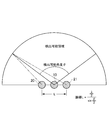
- FIG. 2 is a diagram for explaining the relationship between the detectable angle and the distance between the ultrasonic receivers.
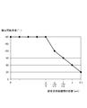
- FIG. 3 is a graph showing the relationship between the detectable angle and the distance between the ultrasonic receivers.
- the moving object detection device 1 transmits ultrasonic waves, receives reflected waves reflected by the moving object by a plurality (two) of ultrasonic receivers 20 and 21, and beats by Doppler shift from the received reflected waves. A signal (frequency shift component) is extracted, and the position (angle) of the moving object is detected based on the phase difference of the beat signal.
- the moving object detection apparatus 1 drives the ultrasonic transmitter 10 that continuously transmits ultrasonic waves, the two ultrasonic receivers 20 and 21 that receive ultrasonic waves, and the ultrasonic transmitter 10.
- a signal processing unit 30 for detecting the position of the moving object from the received signals received by the ultrasonic receivers 20 and 21.
- the signal processing unit 30 includes a transmission signal generation unit 31, a drive circuit 32, a filter / amplification unit 33, a mixer 34, an A / D converter 35, an A / D value acquisition unit 36, a phase difference acquisition unit 37, and a moving object position.
- a detection unit 38 is provided. Hereinafter, each component will be described in detail.
- the ultrasonic transmitter 10 is connected to the signal processing unit 30 via the wiring 25.
- the ultrasonic transmitter 10 drives a piezoelectric element (piezo element) in accordance with an ultrasonic drive signal input from the signal processing unit 30, and continuously transmits, for example, an ultrasonic pulse (ultrasonic signal) of 40 kHz. .
- the two ultrasonic receivers 20 and 21 are transmitted from the ultrasonic transmitter 10 and reflected from the moving object (and / or a stationary object) and returned directly, and directly from the ultrasonic transmitter 10. Receiving ultrasound to reach.
- Each of the ultrasonic receivers 20 and 21 is connected to the signal processing unit 30 via the wirings 26 and 26, and the reception signal output from each of the ultrasonic receivers 20 and 21 is input to the signal processing unit 30. .
- the distance L between the two ultrasonic receivers 20 and 21 shown in FIG. 2 depends on the required detectable angle (that is, the desired detectable angle) and the wavelength of the transmitted ultrasonic wave.
- the phase difference when the ultrasonic wave transmitted from an arbitrary point on the outer edge that defines the detectable region reaches each of the two ultrasonic receivers 20 and 21 is set to be 180 ° or less. In other words, the difference in the lengths of the straight lines connecting any point on the outer edge that defines the detectable region and each of the two ultrasonic receivers 20 and 21 is less than or equal to “ultrasonic wavelength ⁇ / 2”. Is set.
- the distance L between the two ultrasonic receivers 20 and 21 is set based on the following equation (4).
- Distance L ( ⁇ / 2) / sin ( ⁇ / 2) (4)
- ⁇ is the wavelength of the transmitted ultrasonic wave and ⁇ is the desired detectable angle
- the distance L between the ultrasonic receivers 20 and 21 is ⁇ / 2. Therefore, for example, when using a 40 kHz ultrasonic wave, the distance L between the ultrasonic receivers 20 and 21 is set to 4.25 mm or less. Similarly, when the detectable angle is 120 °, the distance L is ⁇ / ⁇ 3 (4.9 mm), and when the detectable angle is 90 °, the distance L is ⁇ / ⁇ 2 (6.0 mm). ), When the detectable angle is 60 °, the distance L is ⁇ (8.5 mm), and when the detectable angle is 30 °, the distance L is 2 ⁇ (17.0 mm).
- FIG. 3 shows the relationship between the detectable angle and the distance between the ultrasonic receivers.
- the distance L between the ultrasonic receivers 20 and 21 decreases.
- the two ultrasonic receivers 20 and 21 are installed side by side within a distance determined according to a desired detectable angle shown in the graph of FIG.
- the ultrasonic transmitter 10 is disposed at the center of a straight line connecting the two ultrasonic receivers 20 and 21 as shown in FIG.
- positioning of the ultrasonic transmitter 10 is not restricted to this example, It can arrange
- the signal processing unit 30 supplies an ultrasonic drive signal to the ultrasonic transmitter 10 to drive the ultrasonic transmitter 10 and processes reflected waves (received signals) received by the ultrasonic receivers 20 and 21. To detect the position of the moving object.
- the signal processing unit 30 includes a drive circuit 32 as an output interface, a filter / amplifier 33 as an input interface, a mixer 34, and an A / D converter 35, and the filter / amplifier 33, mixer 34, A / D.
- a CPU that performs signal processing and the like on a received signal input via the converter 35, a ROM that stores programs and data for causing the CPU to execute each process, and various data such as calculation results are temporarily stored. It is composed of a RAM for storing.
- a program stored in the ROM is executed by the CPU, so that the transmission signal generation unit 31, the A / D value acquisition unit 36, the phase difference acquisition unit 37, and the moving object position detection unit 38 Each function is realized.
- the CPU for example, an ASIC, FPGA, DSP, or the like may be used.
- the transmission signal generation unit 31 generates an ultrasonic drive signal having an ultrasonic frequency (40 kHz in the present embodiment) and outputs the ultrasonic drive signal to the drive circuit 32.
- the drive circuit 32 amplifies the ultrasonic drive signal input from the transmission signal generation unit 31 and supplies the amplified ultrasonic drive signal to the ultrasonic transmitter 10 through the wiring 25. As described above, the ultrasonic transmitter 10 is driven by the ultrasonic drive signal and transmits ultrasonic waves.
- the filter / amplifier 33 is configured by an amplifier circuit using, for example, an operational amplifier, a low-pass filter, a band-pass filter, or the like, and is received by the ultrasonic receivers 20 and 21 and received via the wiring 26. After amplifying the signal, a signal (noise) other than the desired signal is removed. The received signal that has been amplified by the filter / amplifier 33 and from which noise has been removed is output to the mixer 34.
- the mixer 34 mixes (mixes) the reception signals (reflected waves) received by the two ultrasonic receivers 20 and 21 and the ultrasonic drive signals (transmission waves) input from the transmission signal generation unit 31. To extract the beat signal. That is, the mixer 34 functions as a beat extraction unit described in the claims.
- the received waves received by the ultrasonic receivers 20 and 21 include a direct wave directly reaching from the ultrasonic transmitter 10 and a reflected wave reflected by the moving object. The frequency is shifted by Doppler shift.
- a beat signal Doppler frequency component indicated by a one-dot chain line in FIG. 5 is extracted.
- the beat signal extracted by the mixer 34 is output to the A / D converter 35.
- the A / D converter 35 is an analog-digital converter that converts an analog signal into digital data, and converts a beat signal (analog signal) input from the mixer 34 into digital data.
- the A / D value acquisition unit 36 controls the operation of the A / D converter 35 and acquires the beat signal converted into digital data by the A / D converter 35.
- the digital data acquired by the A / D value acquisition unit 36 is output to the phase difference acquisition unit 37.
- the phase difference acquisition unit 37 compares the phases of two beat signals extracted by the mixer 34 and read via the A / D value acquisition unit 36 to obtain a phase difference (see FIG. 5). That is, the phase difference acquisition unit 37 functions as a phase difference acquisition unit described in the claims.
- the acquired phase difference of the beat signal is output to the moving object position detector 38.
- the moving object position detection unit 38 detects the two-dimensional position (relative angle with the moving object) of the moving object based on the phase difference between the two systems of beat signals acquired by the phase difference acquisition unit 37. That is, the moving body position detection unit 38 functions as a position detection unit described in the claims.
- the phase of the beat signal extracted from the received signal of the ultrasonic receiver 20 located on the left side of the drawing in FIG. 2 is the received signal of the ultrasonic receiver 21 located on the right side of the drawing.
- the phase of the beat signal extracted from is delayed. Therefore, in this case, it is detected that a moving object exists on the left side of FIG.
- the angle with the moving object is detected according to the magnitude of the phase difference. Note that the position of the moving object (angle with the moving object) detected by the moving object position detection unit 38 is output to an external device.
- FIG. 6 is a flowchart illustrating a processing procedure of the moving object detection process performed by the moving object detection device 1.
- a continuous ultrasonic drive signal is generated and output.
- the output ultrasonic drive signal is amplified by the drive circuit 32 and supplied to the ultrasonic transmitter 10.
- the ultrasonic transmitter 10 is driven by the supplied ultrasonic drive signal and continuously transmits the ultrasonic signal (step S100).
- the ultrasonic signal transmitted from the ultrasonic transmitter 10 in step S100 propagates through space and is reflected by a moving object (and / or a stationary object).
- the reflected ultrasonic signal returns to the space and is received by the ultrasonic receivers 20 and 21 (step S102).
- the reflected waves received by the ultrasonic receivers 20 and 21 in step S102 are amplified by the filter / amplifier 33 and noise is removed, and then the ultrasonic waves input from the transmission signal generator 31 in the mixer 34 are obtained.
- the beat signal is extracted by mixing with the drive signal (transmission wave) (step S104).
- the beat signal extracted in step S104 is converted into digital data by the A / D converter 35 and read into the phase difference acquisition unit 37 via the A / D value acquisition unit 36. Then, the phase difference acquisition unit 37 compares the phases of the two beat signals to obtain the phase difference (see FIG. 5) (step S106).
- step S108 the two-dimensional position (angle with respect to the moving object) of the moving object is detected based on the phase difference between the two beat signals obtained in step S106. Since the method of detecting the two-dimensional position of the moving object is as described above, detailed description thereof is omitted here. Note that the position of the moving object detected in step S108 is output to an external device.
- two ultrasonic waves are overlapped with an ultrasonic wave directly reaching from the ultrasonic transmitter 10 and a reflected wave reflected by a moving object (that is, a reflected wave whose frequency is shifted by Doppler shift). It is received by the sound wave receivers 20 and 21.
- a beat signal is extracted for each of the two ultrasonic receivers 20 and 21, and the position of the moving object (angle with respect to the moving object) is detected based on the phase difference between the extracted beat signals.
- the distance between the two ultrasonic receivers 20 and 21 is an ultrasonic wave reaching each of the two ultrasonic receivers 20 and 21 based on the desired detectable angle and the wavelength of the transmitted ultrasonic waves.
- the position of the moving object can be detected from the phase difference of the beat signal.
- the position of a moving object can be detected without knowing the speed of the own device, and thus a simpler sensor configuration (that is, the ultrasonic transmitter 10 and the ultrasonic wave).
- the position of the moving object can be detected by only the receivers 20 and 21), and the apparatus can be further downsized. Further, according to the present embodiment, it is possible to detect only a moving object without detecting a stationary object.
- each of the two ultrasonic receivers 20 and 21 is arranged at a desired detectable angle.
- the phase difference of the reaching ultrasonic waves can be 180 ° or less.
- each of the ultrasonic transmitter 10 and the two ultrasonic receivers 20 and 21 uses a short distance (for example, 40 KHz ultrasonic waves and 8.5 mm when the desired detectable angle is 60 °).
- the apparatus can be reduced in size.
- the distance between the two ultrasonic receivers 20 and 21 and the ultrasonic transmitter 10 is equal, the distance between the ultrasonic receivers 20 and 21 and the ultrasonic transmitter 10 is different. Correction of the phase shift of the beat signal caused by this is not necessary. Therefore, it is possible to reduce the processing load such as calculation and to detect the position of the moving object with higher accuracy.
- the moving object detection apparatus 1 includes two ultrasonic receivers 20 and 21 and detects the two-dimensional position of the moving object based on the phase difference between the two systems of beat signals. .
- it can also be set as the structure which has the three ultrasonic receivers 20, 21, and 22 and detects the three-dimensional position of a moving object from the phase difference of each of 3 types of beat signals.
- FIG. 7 is a block diagram illustrating a configuration of the moving object detection device 2.
- the same or equivalent components as those in the first embodiment are denoted by the same reference numerals.
- the moving object detection device 2 includes an ultrasonic receiver 22 and a filter / amplifier 33 that performs processing of a received signal received by the ultrasonic receiver 22.
- the moving object detection apparatus 1 is different in that it further includes a mixer 34 and an A / D converter 35.
- the phase difference acquisition unit 37A is different from the phase difference acquisition unit 37 described above in that the phase difference is acquired by comparing the phases of the three beat signals.
- the moving object position detection unit 38A is different from the moving object position detection unit 38 described above in that it detects the three-dimensional position of the moving object based on the phase difference between the three beat signals.
- these different points will be mainly described.
- Other configurations are the same as or similar to those of the moving object detection device 1 described above, and thus detailed description thereof is omitted here.
- the ultrasonic receiver 22 is transmitted from the ultrasonic transmitter 10 and is reflected by a moving object (and / or a stationary object) and returns to the reflected wave, and The ultrasonic waves that reach directly from the ultrasonic transmitter 10 are received.
- the ultrasonic receiver 22 is connected to the signal processing unit 30A via the wiring 26, and the reception signal output from the ultrasonic receiver 22 is input to the signal processing unit 30A.
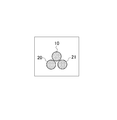
- the three ultrasonic receivers 20, 21, and 22 are arranged so that their intervals are all equal. 8 shows the arrangement of the ultrasonic transmitter 10 and the three ultrasonic receivers 20, 21, 22 constituting the moving object detection apparatus 2 (the ultrasonic transmitter 10 and the ultrasonic receivers 20, 21, 22).
- FIG. 8 shows the arrangement of the ultrasonic transmitter 10 and the three ultrasonic receivers 20, 21, 22 constituting the moving object detection apparatus 2 (the ultrasonic transmitter 10 and the ultrasonic receivers 20, 21, 22).
- the distance from the adjacent ultrasonic receiver is set based on the above-described equation (4). That is, the three ultrasonic receivers 20, 21, and 22 are installed such that the distance between them is within a distance determined according to the desired detectable angle shown in the graph of FIG.
- the ultrasonic transmitter 10 is preferably arranged so that the intervals between the three ultrasonic receivers 20, 21, and 22 are equal.
- the arrangement of the ultrasonic transmitter 10 is not limited to this example, and can be arranged at an arbitrary position. That is, for example, as shown in FIG. 9, the ultrasonic transmitter 10 and the three ultrasonic receivers 20, 21, and 22 may be arranged so as to be located at each vertex of a square.
- FIG. 9 shows another example of the arrangement of the ultrasonic transmitter 10 and the three ultrasonic receivers 20, 21, 22 constituting the moving object detection apparatus 2 (the ultrasonic transmitter 10 and each ultrasonic receiver). 20, 21, and 22 are different from each other). If it arrange
- the phase difference acquisition unit 37A compares the phases of the three beat signals extracted by the mixer 34 and read through the A / D value acquisition unit 36 to obtain a phase difference (see FIG. 10). That is, the phase difference acquisition unit 37A also functions as a phase difference acquisition unit described in the claims. The phase difference of the acquired beat signal is output to the moving object position detection unit 38A.
- the moving object position detection unit 38A detects the three-dimensional position of the moving object (relative angle with the moving object) based on the phase difference of the three systems of beat signals obtained by the phase difference acquisition unit 37A. That is, the moving body position detection unit 38A also functions as the position detection unit described in the claims.
- the phase of the beat signal extracted from the reception signal of the ultrasonic receiver 20 located on the lower left side in FIG. 8 is the reception of the ultrasonic receiver 22 located on the upper side of the figure. It is behind the phase of the beat signal extracted from the signal.
- the beat signal extracted from the received signal of the ultrasonic receiver 20 located on the lower left side of the drawing is the phase of the beat signal extracted from the received signal of the ultrasonic receiver 21 located on the lower right side of the drawing in FIG.
- the three ultrasonic receivers 20, 21, 22 can be used to detect the position of the moving object in three dimensions. Further, according to the present embodiment, the three ultrasonic receivers 20, 21, and 22 are all equal in interval, so that the detectable angle and the inter-receiver distance in each of the ultrasonic receivers 20, 21, and 22. The relationship with is unchanged. Therefore, the same position detection algorithm can be applied. Therefore, it is possible to reduce the processing load such as calculation and to detect the position of the moving object with higher accuracy.
- the present invention is not limited to the above-described embodiments, and various modifications can be made.
- the arrangement of the ultrasonic transmitter 10 and the ultrasonic receivers 20, 21, and 22 and the frequency of the ultrasonic waves to be used are not limited to the above-described embodiment, and for example, required specifications for the moving object detection devices 1 and 2 Can be set arbitrarily.
- the ultrasonic transmitter 10 and the ultrasonic receivers 20, 21, and 22 were arrange
- the moving object detection devices 1 and 2 can be used by being attached to various devices.
- the moving object detection devices 1 and 2 may be attached to a bumper of an automobile to detect the presence / absence / position of a pedestrian and emit a warning sound from a speaker according to the detection result. If it does in this way, a contact accident with a pedestrian can be reduced. In particular, a high effect can be expected in EVs (electric cars and electric motorcycles) where the running sound is quiet.
- the moving object detection devices 1 and 2 are attached to a TV or personal computer monitor, and the presence / absence / position of a person is detected, and the TV / monitor is turned on / off according to the presence / absence of a person. Depending on the position, surround and volume may be adjusted. At that time, since the moving object detection devices 1 and 2 can detect only a moving person, for example, erroneous detection due to a stationary object such as a table or a chair arranged in the vicinity may occur. Absent.
Landscapes
- Engineering & Computer Science (AREA)
- Physics & Mathematics (AREA)
- Radar, Positioning & Navigation (AREA)
- Remote Sensing (AREA)
- Computer Networks & Wireless Communication (AREA)
- General Physics & Mathematics (AREA)
- Acoustics & Sound (AREA)
- Measurement Of Velocity Or Position Using Acoustic Or Ultrasonic Waves (AREA)
Abstract
超音波を利用して移動物体の位置を検出する移動物体検出装置において、シンプルなセンサ構成で、より小型化が可能な移動物体検出装置を提供する。 移動物体検出装置(1)は、超音波を送信する超音波送信機(10)と、移動物体に反射して戻ってくる反射波を受信する2つの超音波受信機(20,21)と、受信された反射波からビート信号を抽出するミキサ(34)と、抽出された2系統のビート信号の位相差を求める位相差取得部(37)と、得られた2系統のビート信号の位相差に基づいて、移動物体の位置を検出する位置検出部(38)とを備えている。上記2つの超音波受信機(20,21)間の距離Lは、次式(1)に基づいて設定される。 距離L=(λ/2)/sin(θ/2) ・・・(1) ただし、λは送信される超音波の波長、θは所望する検出可能角度。
Description
本発明は、超音波を利用して移動物体の位置を検出する移動物体検出装置に関する。
従来から、電波や超音波などの探索波を送信するとともに、物体に反射して戻ってきた反射波を受信し、物体の有無や位置などを検出する装置が知られている。ここで、特許文献1には、送信した電波(又は超音波)の反射波から得られるドップラ信号から、路面に設置された位置マーカと自車との角度を検出する車両位置検出装置が開示されている。
この車両位置検出装置は、車両に搭載されるドップラ検出用センサを有している。ドップラ検出用センサは、予め路面上設置にされた位置マーカに対して周波数f0の電波を探索波として送信する。ここで、車両が速度Vで走行している場合、反射波は、ドップラ効果によって周波数がf0からfiに偏移する。アンテナで受信された周波数fiの反射波は、送信信号の一部とともにミキサに入力され、混合される。ミキサからの出力のうち、周波数fd=f0-fiの成分が可変フィルタで選択され、ドップラ信号として相対速度抽出手段に与えられる。相対速度抽出手段は、次の(1)式から、位置マーカとの相対速度V’を算出する。
fd=2×f0×V’/c ・・・(1)
ここで、cは光速(3×10⁸(m/sec))
位置検出手段は、車両の走行速度Vを車速センサで検出し、走行速度Vと相対速度V’とから、次の(2)式に従って車両の走行方向と位置マーカとの角度θを求める。
V’=Vcosθ ・・・(2)
fd=2×f0×V’/c ・・・(1)
ここで、cは光速(3×10⁸(m/sec))
位置検出手段は、車両の走行速度Vを車速センサで検出し、走行速度Vと相対速度V’とから、次の(2)式に従って車両の走行方向と位置マーカとの角度θを求める。
V’=Vcosθ ・・・(2)
上述した特許文献1記載の車両位置検出装置では、車両の速度Vと、ドップラ信号から算出される相対速度V’とに基づいて、車両と位置マーカとの角度θが求められる。この装置では、車両の速度Vが分かっていないと車両と位置マーカとの角度θを検出できない。すなわち、位置マーカとの角度θを検出するには、車両の速度Vを検出するための車速センサなどが必要なため、センサ構成が複雑で、装置が大型化するおそれがある。そのため、よりシンプルなセンサ構成で(すなわち自車の速度などの検出を要することなく)、例えば小型の携帯機器などにも適用することができる技術が望まれていた。
本発明は、上記問題点を解消する為になされたものであり、超音波を利用して移動物体の位置を検出する移動物体検出装置において、シンプルなセンサ構成で、より小型化が可能な移動物体検出装置を提供することを目的とする。
本発明に係る移動物体検出装置は、超音波を送信する超音波送信機と、超音波送信機により送信され、移動物体に反射して戻ってくる反射波を受信する複数の超音波受信機と、複数の超音波受信機それぞれによって受信された反射波からビート信号を抽出するビート抽出手段と、ビート抽出手段により抽出された複数のビート信号の位相差を求める位相差取得手段と、位相差取得手段により求められた複数のビート信号の位相差に基づいて、移動物体の位置を検出する位置検出手段とを備え、上記複数の超音波受信機間の距離が、所望する検出可能角度と送信される超音波の波長とに応じて、複数の超音波受信機それぞれに到達する超音波の位相差が180°以下となるように設定されることを特徴とする。
ところで、移動物体に超音波が当たると、ドップラシフトにより超音波の周波数が偏移する。本発明に係る移動物体検出装置によれば、移動物体により反射された反射波(すなわちドップラシフトによって周波数が偏移した反射波)が複数の超音波受信機により受信される。そして、複数の超音波受信機毎にビート信号が抽出され、抽出されたビート信号の位相差に基づいて、移動物体の位置が検出される。ここで、複数の超音波受信機間の距離は、所望する検出可能角度と送信される超音波の波長とに基づいて、複数の超音波受信機それぞれに到達する超音波の位相差が180°を越えないように(すなわち半波長以上ずれることがないように)設定されているため、ビート信号の位相差から移動物体の位置を検出することができる。このように、本発明に係る移動物体検出装置によれば、例えば、自機の速度が分からなくても移動物体の位置を検出することができるため、よりシンプルなセンサ構成(すなわち、超音波送信機及び超音波受信機のみ)で移動物体の位置を検出することができ、装置をより小型化することが可能となる。
本発明に係る移動物体検出装置では、上記複数の超音波受信機間の距離が、次式(3)に基づいて設定されることが好ましい。
超音波受信機間の距離L=(λ/2)/sin(θ/2) ・・・(3)
ただし、λは送信される超音波の波長、θは所望する検出可能角度
超音波受信機間の距離L=(λ/2)/sin(θ/2) ・・・(3)
ただし、λは送信される超音波の波長、θは所望する検出可能角度
このような間隔で(すなわち上記(3)式に従って)複数の超音波受信機を配置すれば、所望の検出可能角度において、複数の超音波受信機それぞれに到達する超音波の位相差を180°以下にすることができる。上記(3)式によれば、例えば、40KHzの超音波を用い、所望する検出可能角度が60°の場合には、超音波受信機間の距離は、λ=8.5mm(以下)となる。
本発明に係る移動物体検出装置では、上記複数の超音波受信機それぞれが、超音波送信機との間隔が等しくなるように配置されることが好ましい。
この場合、複数の超音波受信機それぞれと超音波送信機との間隔が等しいため、超音波受信機と超音波送信機との間隔が異なることによって生じるビート信号の位相ずれの補正が不要となる。よって、演算などの処理負荷が軽減されるとともに、より精度良く移動物体の位置を検出することができる。
本発明に係る移動物体検出装置は、3個の超音波受信機を備え、当該3個の超音波受信機が、互いの間隔がすべて等しくなるように配置されることが好ましい。
この場合、3個の超音波受信機について、相互の間隔がすべて等しいため、各超音波受信機において検出可能角度と受信機間距離との関係が異ならない。よって、同一の位置検出アルゴリズムを適用することができる。よって、演算などの処理負荷が軽減されるとともに、より精度良く移動物体の位置を検出することができる。また、3個の超音波受信機を備えることにより、3次元での移動物体の位置を検出することができる。
本発明によれば、超音波を利用して移動物体の位置を検出する移動物体検出装置において、シンプルなセンサ構成で、より小型化が可能となる。
以下、図面を参照して本発明の好適な実施形態について詳細に説明する。なお、各図において、同一要素には同一符号を付して重複する説明を省略する。
[第1実施形態]
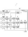
まず、図1~図3を併せて用いて、第1実施形態に係る移動物体検出装置1の構成について説明する。図1は、移動物体検出装置1の構成を示すブロック図である。図2は、検出可能角度と超音波受信機間距離との関係を説明するための図である。また、図3は、検出可能角度と超音波受信機間距離との関係を示すグラフである。
まず、図1~図3を併せて用いて、第1実施形態に係る移動物体検出装置1の構成について説明する。図1は、移動物体検出装置1の構成を示すブロック図である。図2は、検出可能角度と超音波受信機間距離との関係を説明するための図である。また、図3は、検出可能角度と超音波受信機間距離との関係を示すグラフである。
移動物体検出装置1は、超音波を送信するとともに、移動物体によって反射された反射波を複数(2つ)の超音波受信機20,21で受信し、受信された反射波からドップラシフトによるビート信号(周波数偏移成分)を抽出し、該ビート信号の位相差に基づいて、移動物体の位置(角度)を検出するものである。そのために、移動物体検出装置1は、超音波を連続的に送信する超音波送信機10と、超音波を受信する2つの超音波受信機20,21と、超音波送信機10を駆動するとともに、超音波受信機20,21により受信された受信信号から移動物体の位置を検出する信号処理ユニット30とを備えている。この信号処理ユニット30は、送信信号生成部31、駆動回路32、フィルタ/増幅部33、ミキサ34、A/D変換器35、A/D値取得部36、位相差取得部37、及び動体位置検出部38を有している。以下、各構成要素について詳細に説明する。
超音波送信機10は、配線25を介して信号処理ユニット30に接続されている。超音波送信機10は、信号処理ユニット30から入力される超音波駆動信号に応じて、圧電素子(ピエゾ素子)を駆動し、例えば40kHzの超音波パルス(超音波信号)を連続的に送信する。
一方、2つの超音波受信機20,21は、超音波送信機10から送信され、移動物体(及び/又は静止物体)に反射されて戻ってくる反射波、及び、超音波送信機10から直接到達する超音波を受信する。超音波受信機20,21それぞれは、配線26,26を介して信号処理ユニット30に接続されており、超音波受信機20,21それぞれから出力された受信信号は信号処理ユニット30に入力される。
ここで、図2に示される2つの超音波受信機20,21間の距離Lは、要求される検出可能角度(すなわち所望する検出可能角度)と送信される超音波の波長とに応じて、検出可能領域を画定する外縁上の任意の点から送出された超音波が2つの超音波受信機20,21それぞれに到達するときの位相差が180°以下となるように設定される。換言すると、検出可能領域を画定する外縁上の任意の点と2つの超音波受信機20,21それぞれとを結ぶ直線の長さの差が「超音波の波長λ/2」以下となるように設定される。
より具体的には、2つの超音波受信機20,21間の距離Lは、次式(4)に基づいて設定される。
距離L=(λ/2)/sin(θ/2) ・・・(4)
ただし、λは送信される超音波の波長、θは所望する検出可能角度
距離L=(λ/2)/sin(θ/2) ・・・(4)
ただし、λは送信される超音波の波長、θは所望する検出可能角度
よって、所望する検出可能角度が180°の場合には、超音波受信機20,21間の距離Lはλ/2となる。そのため、例えば、40kHzの超音波を使用する場合には、超音波受信機20,21間の距離Lは、4.25mm以下に設定される。同様にして、検出可能角度が120°の場合には、距離Lはλ/√3(4.9mm)、検出可能角度が90°の場合には、距離Lはλ/√2(6.0mm)、検出可能角度が60°の場合には、距離Lはλ(8.5mm)となり、検出可能角度が30°の場合には、距離Lは2λ(17.0mm)となる。
ここで、上述した検出可能角度と超音波受信機間距離との関係を図3に示す。図3に示されるように、所望する検出可能角度が大きくなるほど、超音波受信機20,21間の距離Lは短くなる。このように、2つの超音波受信機20,21は、図3のグラフで示される、所望する検出可能角度に応じて定まる距離以内に並べて設置される。
超音波送信機10は、図2に示されるように、2つの超音波受信機20,21を結ぶ直線の中央に配置される。なお、超音波送信機10の配置は、この例に限られることなく、任意の位置に配置することができる。すなわち、例えば、図4に示されるように、超音波送信機10及び2つの超音波受信機20,21が、正三角形の各頂点に位置するように配置してもよい。ただし、超音波送信機10は、2つの超音波受信機20,21それぞれとの間隔が等しくなるように配置されることが好ましい。
信号処理ユニット30は、超音波送信機10に超音波駆動信号を供給して超音波送信機10を駆動するとともに、超音波受信機20,21により受信された反射波(受信信号)を処理して移動物体の位置を検出する。信号処理ユニット30は、出力インターフェースとしての駆動回路32、入力インターフェースとしてのフィルタ/増幅部33、ミキサ34、並びにA/D変換器35、及び、該フィルタ/増幅部33、ミキサ34、A/D変換器35を介して入力される受信信号に対して信号処理等を行うCPU、該CPUに各処理を実行させるためのプログラムやデータ等を記憶するROM、演算結果などの各種データを一時的に記憶するRAM等により構成されている。信号処理ユニット30では、ROMに記憶されているプログラムが、CPUによって実行されることにより、送信信号生成部31、A/D値取得部36、位相差取得部37、及び動体位置検出部38の各機能が実現される。なお、CPUに代えて、例えばASICや、FPGA、DSPなどを用いてもよい。
送信信号生成部31は、超音波周波数(本実施形態では40kHz)の超音波駆動信号を生成し、駆動回路32へ出力する。駆動回路32は、送信信号生成部31から入力された超音波駆動信号を増幅し、配線25を通して超音波送信機10に供給する。上述したように、超音波送信機10は、この超音波駆動信号によって駆動され、超音波を送信する。
フィルタ/増幅部33は、例えばオペアンプ等を用いた増幅回路、及び、ローパスフィルタ又はバンドパスフィルタ等によって構成されており、超音波受信機20,21それぞれにより受信され、配線26を通して入力された受信信号を増幅した後、所望の信号以外の信号(ノイズ)を除去する。フィルタ/増幅部33で増幅され、ノイズが除去された受信信号は、ミキサ34に出力される。
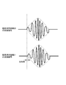
ミキサ34は、2つの超音波受信機20,21それぞれによって受信された受信信号(反射波)と、送信信号生成部31から入力される超音波駆動信号(送信波)とをミキシング(混合)してビート信号を抽出するものである。すなわち、ミキサ34は、請求の範囲に記載のビート抽出手段として機能する。ここで、超音波受信機20,21で受信される受信波には、超音波送信機10から直接届く直接波と移動物体に反射された反射波とを含んでいるが、このうち、反射波はドップラシフトによって周波数が偏移している。超音波駆動信号(送信波)と受信波(反射波)とがミキサ34で混合されることで、図5に一点鎖線で示されるビート信号(ドップラ周波数成分)が抽出される。なお、ミキサ34により抽出されたビート信号はA/D変換器35に出力される。
A/D変換器35は、アナログ信号をディジタルデータに変換するアナログ-ディジタル変換器であり、ミキサ34から入力されるビート信号(アナログ信号)をディジタルデータに変換する。A/D値取得部36は、A/D変換器35の動作を制御し、A/D変換器35によりディジタルデータ化されたビート信号を取得する。なお、A/D値取得部36で取得されたディジタルデータは、位相差取得部37に出力される。
位相差取得部37は、ミキサ34により抽出され、A/D値取得部36を介して読み込まれた2系統のビート信号の位相を比較して位相差(図5参照)を求める。すなわち、位相差取得部37は、請求の範囲に記載の位相差取得手段として機能する。取得されたビート信号の位相差は、動体位置検出部38に出力される。
動体位置検出部38は、位相差取得部37により取得された2系統のビート信号の位相差に基づいて、移動物体の2次元位置(移動物体との相対的な角度)を検出する。すなわち、動体位置検出部38は、請求の範囲に記載の位置検出手段として機能する。例えば、図5に示された例では、図2において図面左側に位置する超音波受信機20の受信信号から抽出されたビート信号の位相が、図面右側に位置する超音波受信機21の受信信号から抽出されたビート信号の位相よりも遅れている。そのため、この場合には、図2において図面左側に移動物体が存在することが検出される。なお、位相差の大きさに応じて、移動物体との角度が検出される。なお、動体位置検出部38により検出された移動物体の位置(移動物体との角度)は、外部機器に出力される。
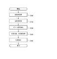
次に、図6を参照しつつ、移動物体検出装置1の動作について説明する。図6は、移動物体検出装置1による移動物体検出処理の処理手順を示すフローチャートである。
まず、送信信号生成部31において、連続的な超音波駆動信号が生成され、出力される。出力された超音波駆動信号は、駆動回路32で増幅されて超音波送信機10に供給される。超音波送信機10は、供給された超音波駆動信号によって駆動され、超音波信号を連続的に送信する(ステップS100)。
ステップS100において超音波送信機10から送信された超音波信号は、空間を伝搬し、移動物体(及び/又は静止物体)で反射される。反射された超音波信号は、空間を戻り、超音波受信機20,21によって受信される(ステップS102)。
ステップS102において超音波受信機20,21それぞれによって受信された反射波は、フィルタ/増幅部33で増幅されてノイズが除去された後、ミキサ34において、送信信号生成部31から入力される超音波駆動信号(送信波)とミキシングされてビート信号が抽出される(ステップS104)。
ステップS104において抽出されたビート信号は、A/D変換器35によりディジタルデータに変換され、A/D値取得部36を介して位相差取得部37に読み込まれる。そして、位相差取得部37により2系統のビート信号の位相が比較されて位相差(図5参照)が求められる(ステップS106)。
続くステップS108では、ステップS106において求められた2系統のビート信号の位相差に基づいて、移動物体の2次元位置(移動物体との角度)が検出される。移動物体の2次元位置の検出の仕方については、上述した通りであるので、ここでは詳細な説明を省略する。なお、ステップS108において検出された移動物体の位置は、外部機器に出力される。
本実施形態によれば、超音波送信機10から直接到達した超音波と、移動物体により反射された反射波(すなわちドップラシフトによって周波数が偏移した反射波)とが重なり合った状態で2つの超音波受信機20,21により受信される。そして、2つの超音波受信機20,21毎にビート信号が抽出され、抽出されたビート信号の位相差に基づいて、移動物体の位置(移動物体との角度)が検出される。ここで、2つの超音波受信機20,21間の距離は、所望する検出可能角度と送信される超音波の波長とに基づいて、2つの超音波受信機20,21それぞれに到達する超音波の位相差が180°を越えないように(すなわち半波長以上ずれることがないように)設定されている。そのため、ビート信号の位相差から移動物体の位置を検出することができる。このように、本実施形態によれば、例えば、自機の速度が分からなくても移動物体の位置を検出することができるため、よりシンプルなセンサ構成(すなわち、超音波送信機10及び超音波受信機20,21のみ)で移動物体の位置を検出することができ、装置をより小型化することが可能となる。また、本実施形態によれば、静止物体は検知することなく、移動物体のみを検出することができる。
特に、本実施形態によれば、上記(4)式に従って、2つの超音波受信機20,21が配置されているため、所望の検出可能角度において、2つの超音波受信機20,21それぞれに到達する超音波の位相差を180°以下にすることができる。その際に、超音波送信機10及び2つの超音波受信機20,21それぞれは、近距離(例えば、40KHzの超音波を用い、所望する検出可能角度が60°の場合には、8.5mm以下)に配置されることとなるため、装置を小型化することができる。
また、本実施形態によれば、2つの超音波受信機20,21それぞれと超音波送信機10との間隔が等しいため、超音波受信機20,21と超音波送信機10との間隔が異なることによって生じるビート信号の位相ずれの補正が不要となる。よって、演算などの処理負荷を軽減できるとともに、より精度良く移動物体の位置を検出することが可能となる。
[第2実施形態]
上述した、第1実施形態に係る移動物体検出装置1は、2つの超音波受信機20,21を有し、2系統のビート信号の位相差に基づいて、移動物体の2次元位置を検出した。これに対して、3つの超音波受信機20,21,22を有し、3系統のビート信号それぞれの位相差から、移動物体の3次元位置を検出する構成とすることもできる。次に、図7を参照しつつ、第2実施形態に係る移動物体検出装置2の構成について説明する。図7は、移動物体検出装置2の構成を示すブロック図である。なお、図7において第1実施形態と同一又は同等の構成要素については同一の符号が付されている。
上述した、第1実施形態に係る移動物体検出装置1は、2つの超音波受信機20,21を有し、2系統のビート信号の位相差に基づいて、移動物体の2次元位置を検出した。これに対して、3つの超音波受信機20,21,22を有し、3系統のビート信号それぞれの位相差から、移動物体の3次元位置を検出する構成とすることもできる。次に、図7を参照しつつ、第2実施形態に係る移動物体検出装置2の構成について説明する。図7は、移動物体検出装置2の構成を示すブロック図である。なお、図7において第1実施形態と同一又は同等の構成要素については同一の符号が付されている。
移動物体検出装置2は、上述した移動物体検出装置1の構成に加えて、超音波受信機22、及び、該超音波受信機22により受信された受信信号の処理を行うフィルタ/増幅部33、ミキサ34、A/D変換器35をさらに有している点で移動物体検出装置1と異なっている。また、位相差取得部37Aは、3系統のビート信号の位相を比較して位相差を取得する点で、上述した位相差取得部37と異なっている。さらに、動体位置検出部38Aは、3系統のビート信号の位相差に基づいて、移動物体の3次元位置を検出する点で、上述した動体位置検出部38と異なっている。以下、これらの異なる点を中心に説明する。その他の構成は、上述した移動物体検出装置1と同一または同様であるので、ここでは詳細な説明を省略する。
超音波受信機22は、上述した超音波受信機20,21と同様に、超音波送信機10か送信され、移動物体(及び/又は静止物体)に反射されて戻ってくる反射波、及び、超音波送信機10から直接到達する超音波を受信する。超音波受信機22は、配線26を介して信号処理ユニット30Aに接続されており、超音波受信機22から出力された受信信号は信号処理ユニット30Aに入力される。ここで、3つの超音波受信機20,21,22は、図8に示されるように、互いの間隔がすべて等しくなるように配置される。なお、図8は、移動物体検出装置2を構成する超音波送信機10と3つの超音波受信機20,21,22の配置(超音波送信機10と各超音波受信機20,21,22との距離が等しい場合)を示す図である。
ここで、図8に示される3つの超音波受信機20,21,22それぞれは、互いに隣り合う超音波受信機との距離が、上述した式(4)に基づいて設定される。すなわち、3つの超音波受信機20,21,22は、互いの距離が、上述した図3のグラフで示される、所望する検出可能角度に応じて定まる距離以内になるように設置される。
また、図8に示されるように、超音波送信機10は、3つの超音波受信機20,21,22それぞれとの間隔が等しくなるように配置されることが好ましい。ただし、超音波送信機10の配置は、この例に限られることなく、任意の位置に配置することができる。すなわち、例えば図9に示されるように、超音波送信機10及び3つの超音波受信機20,21,22が、正方形の各頂点に位置するように配置してもよい。ここで、図9は、移動物体検出装置2を構成する超音波送信機10と3つの超音波受信機20,21,22の配置の他の例(超音波送信機10と各超音波受信機20,21,22との距離が異なる場合)を示す図である。図9に示されるように配置すれば、超音波送信機10及び超音波受信機20,21,22の取付け面積をより小さくすることができる。
位相差取得部37Aは、ミキサ34により抽出され、A/D値取得部36を介して読み込まれた3系統のビート信号の位相を比較して位相差(図10参照)を求める。すなわち、位相差取得部37Aも、請求の範囲に記載の位相差取得手段として機能する。取得されたビート信号の位相差は、動体位置検出部38Aに出力される。
動体位置検出部38Aは、位相差取得部37Aにより求められた3系統のビート信号の位相差に基づいて、移動物体の3次元位置(移動物体との相対的な角度)を検出する。すなわち、動体位置検出部38Aも、請求の範囲に記載の位置検出手段として機能する。
例えば、図10に示された例では、図8において図面左下側に位置する超音波受信機20の受信信号から抽出されたビート信号の位相が、図面上側に位置する超音波受信機22の受信信号から抽出されたビート信号の位相よりも遅れている。かつ、図8において図面右下側に位置する超音波受信機21の受信信号から抽出されたビート信号の位相が、図面左下側に位置する超音波受信機20の受信信号から抽出されたビート信号の位相、及び、図面上側に位置する超音波受信機22の受信信号から抽出されたビート信号の位相よりも遅れている。そのため、この場合には、超音波送信機10及び超音波受信機20,21,22の取付面から見て左上方に移動物体が存在することが検出される。なお、位相差の大きさに応じて、移動物体との角度が検出される。なお、動体位置検出部38Aにより検出された移動物体の位置(移動物体との角度)は、外部機器に出力される。
本実施形態によれば、3個の超音波受信機20,21,22を有することにより、3次元での移動物体の位置を検出することができる。また、本実施形態によれば、3個の超音波受信機20,21,22について、相互の間隔がすべて等しいため、各超音波受信機20,21,22において検出可能角度と受信機間距離との関係が変わらない。よって、同一の位置検出アルゴリズムを適用することができる。よって、演算などの処理負荷を軽減できるとともに、より精度良く移動物体の位置を検出することが可能となる。
以上、本発明の実施の形態について説明したが、本発明は、上記実施形態に限定されるものではなく種々の変形が可能である。例えば、超音波送信機10及び超音波受信機20,21,22の配置や使用する超音波の周波数などは上記実施形態に限られることなく、例えば、移動物体検出装置1,2に対する要求仕様などによって任意に設定され得る。その際に、上記実施形態では、超音波送信機10及び超音波受信機20,21,22を同一平面上に配置したが、これらを立体的に配置してもよい。
また、移動物体検出装置1,2は、さまざまな機器に取り付けて利用することができる。例えば、移動物体検出装置1,2を自動車のバンパーに取り付けて、歩行者の有無・位置を検出し、検出結果に応じて、スピーカから警告音を発するようにしてもよい。このようにすれば、歩行者との接触事故を低減することができる。特に、走行音が静かなEV(電気自動車や電動バイク)において高い効果が期待できる。
また、例えば、移動物体検出装置1,2をテレビやパソコンのモニタに取り付け、人の有無・位置を検出し、人の有無に応じて、テレビやモニタの電源をON/OFFしたり、人の位置に応じて、サラウンドや音量を調整するようにしてもよい。なお、その際に、移動物体検出装置1,2によれば、動く人のみを検知することができるため、例えば、周辺に配置されているテーブルや椅子などの静止物体による誤検知を生じることはない。
1,2 移動物体検出装置
10 超音波送信機
20,21,22 超音波受信機
30,30A 信号処理ユニット
31 送信信号生成部
32 駆動回路
33 フィルタ/増幅部
34 ミキサ
35 A/D変換器
36 A/D値取得部
37,37A 位相差取得部
38,38A 動体位置検出部
10 超音波送信機
20,21,22 超音波受信機
30,30A 信号処理ユニット
31 送信信号生成部
32 駆動回路
33 フィルタ/増幅部
34 ミキサ
35 A/D変換器
36 A/D値取得部
37,37A 位相差取得部
38,38A 動体位置検出部
Claims (4)
- 超音波を送信する超音波送信機と、
前記超音波送信機により送信され、移動物体に反射して戻ってくる反射波を受信する複数の超音波受信機と、
前記複数の超音波受信機それぞれによって受信された前記反射波からビート信号を抽出するビート抽出手段と、
前記ビート抽出手段により抽出された複数のビート信号の位相差を求める位相差取得手段と、
前記位相差取得手段により求められた前記複数のビート信号の位相差に基づいて、前記移動物体の位置を検出する位置検出手段と、
を備え、
前記複数の超音波受信機間の距離は、所望する検出可能角度と送信される超音波の波長とに応じて、前記複数の超音波受信機それぞれに到達する超音波の位相差が180°以下となるように設定されることを特徴とする移動物体検出装置。 - 前記複数の超音波受信機間の距離は、次式(1)に基づいて設定されることを特徴とする請求項1に記載の移動物体検出装置。
超音波受信機間の距離L=(λ/2)/sin(θ/2) ・・・(1)
ただし、λは送信される超音波の波長、θは所望する検出可能角度 - 前記複数の超音波受信機それぞれは、前記超音波送信機との間隔が等しくなるように配置されることを特徴とする請求項1又は2に記載の移動物体検出装置。
- 3個の超音波受信機を備え、
前記3個の超音波受信機は、互いの間隔がすべて等しくなるように配置されることを特徴とする請求項3に記載の移動物体検出装置。
Applications Claiming Priority (2)
| Application Number | Priority Date | Filing Date | Title |
|---|---|---|---|
| JP2011098004 | 2011-04-26 | ||
| JP2011-098004 | 2011-04-26 |
Publications (1)
| Publication Number | Publication Date |
|---|---|
| WO2012147284A1 true WO2012147284A1 (ja) | 2012-11-01 |
Family
ID=47071818
Family Applications (1)
| Application Number | Title | Priority Date | Filing Date |
|---|---|---|---|
| PCT/JP2012/002396 Ceased WO2012147284A1 (ja) | 2011-04-26 | 2012-04-05 | 移動物体検出装置 |
Country Status (1)
| Country | Link |
|---|---|
| WO (1) | WO2012147284A1 (ja) |
Cited By (2)
| Publication number | Priority date | Publication date | Assignee | Title |
|---|---|---|---|---|
| EP2908153A3 (de) * | 2014-02-14 | 2016-01-13 | Volkswagen Aktiengesellschaft | Erkennung dynamischer Objekte mittels Ultraschall |
| US20190204432A1 (en) * | 2018-01-04 | 2019-07-04 | Auspion, Inc. | Three-dimensional and four-dimensional mapping of space using microwave and mm-wave parallax |
Citations (3)
| Publication number | Priority date | Publication date | Assignee | Title |
|---|---|---|---|---|
| JP2003139855A (ja) * | 2001-11-05 | 2003-05-14 | Koden Electronics Co Ltd | 超音波探査装置 |
| JP2006343309A (ja) * | 2005-05-09 | 2006-12-21 | Nippon Soken Inc | 障害物検出装置 |
| JP2010151496A (ja) * | 2008-12-24 | 2010-07-08 | Nippon Soken Inc | 方位検出装置 |
-
2012
- 2012-04-05 WO PCT/JP2012/002396 patent/WO2012147284A1/ja not_active Ceased
Patent Citations (3)
| Publication number | Priority date | Publication date | Assignee | Title |
|---|---|---|---|---|
| JP2003139855A (ja) * | 2001-11-05 | 2003-05-14 | Koden Electronics Co Ltd | 超音波探査装置 |
| JP2006343309A (ja) * | 2005-05-09 | 2006-12-21 | Nippon Soken Inc | 障害物検出装置 |
| JP2010151496A (ja) * | 2008-12-24 | 2010-07-08 | Nippon Soken Inc | 方位検出装置 |
Cited By (3)
| Publication number | Priority date | Publication date | Assignee | Title |
|---|---|---|---|---|
| EP2908153A3 (de) * | 2014-02-14 | 2016-01-13 | Volkswagen Aktiengesellschaft | Erkennung dynamischer Objekte mittels Ultraschall |
| US20190204432A1 (en) * | 2018-01-04 | 2019-07-04 | Auspion, Inc. | Three-dimensional and four-dimensional mapping of space using microwave and mm-wave parallax |
| US12007466B2 (en) * | 2018-01-04 | 2024-06-11 | GuRu Wireless, Inc. | Three-dimensional and four-dimensional mapping of space using microwave and MM-wave parallax |
Similar Documents
| Publication | Publication Date | Title |
|---|---|---|
| JP5228602B2 (ja) | 物体検出装置 | |
| CN103168250B (zh) | 用于物体检测的方法和装置 | |
| JP2017215328A (ja) | アンテナローブが狭く、かつ角度検出範囲が広いイメージング・レーダセンサ | |
| JP2004537730A (ja) | 移動体電話局から送信される信号を用いた受動式移動体検知システム及び方法 | |
| JP3821688B2 (ja) | レーダ装置 | |
| US20210325531A1 (en) | Radar device, observation target detecting method, and in-vehicle device | |
| KR101552283B1 (ko) | 표면탄성파 센서를 이용한 온도 및 거리 동시 측정 시스템 | |
| JP2017090078A (ja) | 電波センサ、検知方法および検知プログラム | |
| CN107957580A (zh) | 超声波传感器装置及超声波传感器装置的感测方法 | |
| EP2799905B1 (en) | High sensitive apparatus for car parking ultrasonic sensors and method thereof | |
| CN111198368A (zh) | 生物探测方法及生物探测雷达 | |
| EP1324066A3 (en) | FM Radar Device | |
| CN111051918A (zh) | 雷达装置以及具备该雷达装置的汽车 | |
| JP5899698B2 (ja) | 人体部位位置測定装置および電子機器システム | |
| WO2012147284A1 (ja) | 移動物体検出装置 | |
| JP5370132B2 (ja) | 障害物検出装置 | |
| JP5392410B2 (ja) | レーダ装置 | |
| JP5506214B2 (ja) | 地中レーダ装置 | |
| JP2002062352A (ja) | 車載用レーダ装置 | |
| JP4103597B2 (ja) | 誘導装置 | |
| JP4627749B2 (ja) | 車載用レーダ装置 | |
| JP2013044697A (ja) | ドップラ式速度計 | |
| JP3865761B2 (ja) | レーダ装置 | |
| CN114578363B (zh) | 一种超声波检测系统和方法 | |
| JP6815785B2 (ja) | 超音波変位計測装置及び超音波変位計測方法 |
Legal Events
| Date | Code | Title | Description |
|---|---|---|---|
| 121 | Ep: the epo has been informed by wipo that ep was designated in this application |
Ref document number: 12776487 Country of ref document: EP Kind code of ref document: A1 |
|
| NENP | Non-entry into the national phase |
Ref country code: DE |
|
| 122 | Ep: pct application non-entry in european phase |
Ref document number: 12776487 Country of ref document: EP Kind code of ref document: A1 |
|
| NENP | Non-entry into the national phase |
Ref country code: JP |