WO2012147165A1 - 車両挙動制御システム - Google Patents
車両挙動制御システム Download PDFInfo
- Publication number
- WO2012147165A1 WO2012147165A1 PCT/JP2011/060175 JP2011060175W WO2012147165A1 WO 2012147165 A1 WO2012147165 A1 WO 2012147165A1 JP 2011060175 W JP2011060175 W JP 2011060175W WO 2012147165 A1 WO2012147165 A1 WO 2012147165A1
- Authority
- WO
- WIPO (PCT)
- Prior art keywords
- control
- wheel
- pressure
- vehicle
- braking
- Prior art date
- Legal status (The legal status is an assumption and is not a legal conclusion. Google has not performed a legal analysis and makes no representation as to the accuracy of the status listed.)
- Ceased
Links
Images




Classifications
-
- B—PERFORMING OPERATIONS; TRANSPORTING
- B60—VEHICLES IN GENERAL
- B60T—VEHICLE BRAKE CONTROL SYSTEMS OR PARTS THEREOF; BRAKE CONTROL SYSTEMS OR PARTS THEREOF, IN GENERAL; ARRANGEMENT OF BRAKING ELEMENTS ON VEHICLES IN GENERAL; PORTABLE DEVICES FOR PREVENTING UNWANTED MOVEMENT OF VEHICLES; VEHICLE MODIFICATIONS TO FACILITATE COOLING OF BRAKES
- B60T8/00—Arrangements for adjusting wheel-braking force to meet varying vehicular or ground-surface conditions, e.g. limiting or varying distribution of braking force
- B60T8/17—Using electrical or electronic regulation means to control braking
- B60T8/1755—Brake regulation specially adapted to control the stability of the vehicle, e.g. taking into account yaw rate or transverse acceleration in a curve
Definitions
- the present invention relates to a vehicle behavior control system.
- Patent Document 1 discloses a behavior of a vehicle that restricts an increasing gradient of wheel cylinder pressure supplied to a wheel cylinder when performing ABS control while performing turning control such as so-called VSC control.
- a control device is disclosed.
- This vehicle behavior control device includes a high-pressure accumulator mechanism such as an accumulator, and is a so-called hydro booster type using a hydraulic booster that amplifies pedal depression force input to a brake pedal from a driver using hydraulic pressure.
- the actuator is provided.
- This actuator has a common switching valve that switches the hydraulic pressure supplied to the wheel cylinders of a plurality of wheels to a regulator pressure corresponding to the master cylinder pressure and an accumulator pressure.
- the vehicle behavior control device supplies the accumulator pressure to the wheel cylinder and the ABS when the spin suppression control for controlling the turning state of the vehicle and the ABS control for controlling the slip state of the wheel are executed simultaneously. Control is performed to limit the pressure increase gradient of the braking pressure (wheel cylinder pressure) of the wheel for which control is executed to a small value.
- the vehicle behavior control apparatus described in Patent Document 1 as described above has room for further improvement in terms of stabilizing the behavior of the vehicle, for example.
- the present invention has been made in view of the above circumstances, and an object thereof is to provide a vehicle behavior control system capable of stabilizing the behavior of a vehicle.
- a vehicle behavior control system controls a braking device capable of individually adjusting a braking force generated on each wheel of a vehicle, and controls the braking device to control a slip state of the wheel.
- a control device capable of executing a turn control for controlling a turning state of the vehicle, and the control device is configured to control a lateral acceleration acting on the vehicle during the operation of the ABS control and the turn control.
- the increase gradient of the braking force is limited when the absolute value is less than or equal to a predetermined value set in advance, while the increase gradient of the braking force is not limited when the absolute value of the lateral acceleration is larger than the predetermined value. It is characterized by.
- the control device is controlling the behavior of the vehicle in a state where the absolute value of the lateral acceleration is greater than the predetermined value and does not limit the increase gradient of the braking force. Even when the absolute value of the lateral acceleration becomes equal to or less than the predetermined value, the state in which the increasing gradient of the braking force is not limited can be continued.
- the braking device is configured to increase the operating force input to the braking operation member using a negative pressure, and the operating force increased by the booster.
- a master cylinder that applies an operating pressure to the working fluid
- a wheel cylinder that is provided on each wheel and that generates a braking force by applying a braking pressure based on the operating pressure, and is supplied to the wheel cylinder. It is possible to have an actuator capable of individually adjusting the braking force generated in each wheel by individually adjusting the braking pressure.
- the vehicle behavior control system according to the present invention has an effect that the behavior of the vehicle can be stabilized.
- FIG. 1 is a schematic configuration diagram of a vehicle according to an embodiment.
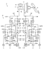
- FIG. 2 is a schematic configuration diagram illustrating an example of a braking device according to the embodiment.
- FIG. 3 is a schematic cross-sectional view illustrating an example of a control valve of the VSC actuator according to the embodiment.
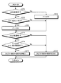
- FIG. 4 is a flowchart illustrating an example of control by the ECU according to the embodiment.
- FIG. 5 is a diagram illustrating an example of a limited control map according to the embodiment.
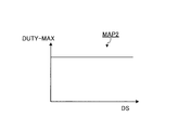
- FIG. 6 is a diagram illustrating an example of an unrestricted control map according to the embodiment.
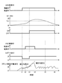
- FIG. 7 is a time chart for explaining an example of control by the ECU according to the embodiment.
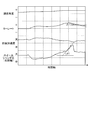
- FIG. 8 is a time chart for explaining behavior in the vehicle behavior control system according to the embodiment.
- FIG. 9 is a time chart for explaining the behavior in the vehicle behavior control system according to the comparative example.
- FIG. 1 is a schematic configuration diagram of a vehicle according to the embodiment
- FIG. 2 is a schematic configuration diagram illustrating an example of a braking device according to the embodiment
- FIG. 3 is a schematic diagram illustrating an example of a control valve of a VSC actuator according to the embodiment.
- FIG. 4 is a flowchart for explaining an example of control by the ECU according to the embodiment
- FIG. 5 is a diagram showing an example of a limited control map according to the embodiment
- FIG. 6 is no restriction according to the embodiment.
- FIG. 7 is a time chart for explaining an example of control by the ECU according to the embodiment
- FIG. 8 is a time chart for explaining behavior in the vehicle behavior control system according to the embodiment
- FIG. These are time charts explaining the behavior in the vehicle behavior control system according to the comparative example.
- the present embodiment is typically applied to a vehicle and has the following components.
- VSC actuator one that can control the wheel cylinder hydraulic pressure independently of the four wheels and has no high pressure accumulator such as an accumulator).
- An ECU that integrates and controls the above.
- Those connecting the above CAN, wire harness, etc.).
- VSC Vehicle Stability Control
- ABS Antilock Brake System
- the effect of stabilizing the behavior by the VSC control can be appropriately obtained by not limiting the pressure increase gradient of the braking hydraulic pressure.
- the mode in which the pressure increase gradient is limited even when the lateral acceleration becomes a predetermined value or less is entered when the mode in which the pressure increase gradient is not limited in the VSC control is entered. Do not return to.
- a vehicle behavior control system 1 is mounted on a vehicle 2 as shown in FIG. 1, and is a system for controlling the vehicle 2. Typically, a braking force generated on a wheel 3 of the vehicle 2 is applied. It is a system that controls the slip state of each wheel 3 and the turning state of the vehicle 2 by controlling to stabilize the behavior of the vehicle 2.
- the vehicle 2 includes a left front wheel 3FL, a right front wheel 3FR, a left rear wheel 3RL, and a right rear wheel 3RR as the wheels 3, but these are simply referred to as wheels 3 when it is not necessary to separate them.
- the vehicle behavior control system 1 includes an accelerator pedal 4, a drive source 5, a brake pedal 6, a braking device 7, an ECU 8 as a control device (vehicle control device), and the like.
- the drive source 5 generates power (torque) according to the operation of the accelerator pedal 4 by the driver, and this power is transmitted to the wheels 3 via a power transmission device (not shown). Generate driving force.
- the vehicle 2 generates a braking force on the wheel 3 by operating the braking device 7 according to the operation of the brake pedal 6 by the driver.
- the drive source 5 is a driving power source such as an internal combustion engine.
- the braking device 7 can individually adjust the braking force generated on each wheel 3 of the vehicle 2.
- the brake device 7 is a variety of hydraulic brake devices in which brake oil as working fluid is filled in a hydraulic path connected from the master cylinder 9 to the wheel cylinder 11 via the VSC actuator 10.
- the hydraulic braking unit 12 operates according to the braking pressure supplied to the wheel cylinder 11 to generate a pressure braking force on the wheel 3.
- the braking device 7 will be described in detail later.
- the ECU 8 controls driving of each part of the vehicle 2 and includes an electronic circuit mainly composed of a known microcomputer including a CPU, a ROM, a RAM, and an interface.
- the ECU 8 is generated in, for example, each wheel speed sensor 13 that detects the rotational speed of each wheel 3, a steering angle sensor 14 that detects the steering angle of the vehicle 2, a yaw rate sensor 15 that detects the yaw rate of the vehicle 2, and the vehicle body of the vehicle 2.
- Various sensors and detection devices attached to various parts of the vehicle 2 such as a lateral acceleration sensor 16 for detecting acceleration in the lateral direction (direction intersecting (orthogonal to) the traveling direction) are electrically connected, and electricity corresponding to the detection result A signal is input.
- the ECU 8 drives each part of the vehicle 2 such as the drive source 5 and the VSC actuator 10 of the braking device 7 by executing a stored control program based on various input signals and various maps input from various sensors. A signal is output to control these driving operations.
- the ECU 8 of this embodiment controls the VSC actuator 10 according to the traveling state of the vehicle 2 and individually increases or decreases the wheel cylinder pressures of the wheel cylinders 11 provided on the wheels 3, respectively.
- the ECU 8 controls, for example, ABS control for controlling the braking device 7 to control the slip state of the wheels 3, and turning for controlling the turning state of the vehicle 2 by controlling the braking device 7.
- VSC control or the like as control can be executed.
- the VSC actuator 10 provided in the braking device 7 of the present embodiment includes an accumulator or the like, and uses a hydraulic booster that uses a hydraulic pressure to amplify the pedal depression force input from the driver to the brake pedal 6. It is not a booster type hydraulic actuator, but a so-called vacuum booster type hydraulic actuator.
- This vacuum booster type VSC actuator 10 is capable of individually increasing, reducing and maintaining the wheel cylinder hydraulic pressure independently of the four wheels, and does not include a high pressure accumulating mechanism such as an accumulator.
- a vacuum booster (negative pressure assisting device) that amplifies the pedal depression force input from the driver to the brake pedal 6 using the negative pressure supplied from the internal combustion engine or the like is used.
- the braking device 7 is increased by a vacuum booster 17 as a negative pressure booster that increases the pedal depression force (operation force) input to the brake pedal 6 as a braking operation member by using negative pressure, and a vacuum booster 17.
- a master cylinder 9 that applies a master cylinder pressure (operating pressure) to brake oil (working fluid) according to the pedal depression force, and a wheel cylinder pressure (braking pressure) based on the master cylinder pressure provided on each wheel 3 acts.
- the wheel cylinder 11 that generates the braking force on each wheel 3 and the actuator that can individually adjust the braking force generated on each wheel 3 by individually adjusting the wheel cylinder pressure supplied to the wheel cylinder 11 VSC actuator 10 and calipers, brake pads, disc rotors, etc.
- a hydraulic brake unit 12 constituted in, having a reservoir 18 for storing excess brake fluid.
- the braking device 7 basically applies a master cylinder pressure to the brake oil by the master cylinder 9 according to the pedal depression force acting on the brake pedal 6 when the driver operates the brake pedal 6.
- the master cylinder pressure acts as the wheel cylinder pressure in each wheel cylinder 11, so that the hydraulic braking unit 12 is activated and generates a pressure braking force on the wheel 3.
- the brake pedal 6 is operated by the driver in response to a braking request when the driver generates a braking force on the vehicle 2.
- the master cylinder 9 pressurizes the brake oil by a piston interlocked with the brake pedal 6 when a pedal depression force is input from the driver to the brake pedal 6, and applies a master cylinder pressure corresponding to the pedal depression force. That is, the master cylinder 9 converts the pedal depression force input via the brake pedal 6 into a master cylinder pressure corresponding to the pedal depression force.
- the reservoir 18 is connected to the master cylinder 9 and stores brake oil therein. The reservoir 18 and the master cylinder 9 communicate with each other when the brake pedal 6 is not depressed. When the brake pedal 6 is depressed, the communication is cut off, and the brake oil is pressurized in the master cylinder 9.
- the vacuum booster 17 is integrally attached to the master cylinder 9 and is connected to an intake path (intake passage) of an internal combustion engine (engine) that forms the drive source 5 via a negative pressure pipe or the like, and generates negative pressure generated in the internal combustion engine. Is supplied.
- the vacuum booster 17 amplifies the pedal depression force by a force acting on a diaphragm (not shown) according to a differential pressure between a supplied negative pressure and a pressure due to outside air.
- the vacuum booster 17 increases the pedal depression force when the brake pedal 6 is braked by negative pressure, and increases the pedal depression force input to the master cylinder 9 with respect to the pedal depression force input to the brake pedal 6.
- the pedal depression force applied to the brake pedal 6 can be reduced.
- the master cylinder 9 pressurizes the brake oil according to the pedal depression force amplified by the vacuum booster 17 and applies the master cylinder pressure to the brake oil.
- the VSC actuator 10 is provided on the hydraulic path of brake oil that connects the master cylinder 9 and the wheel cylinder 11, and increases or decreases the hydraulic pressure in each wheel cylinder 11 by control by the ECU 8 separately from the brake operation of the brake pedal 6. The braking force applied to each wheel 3 is controlled.
- the VSC actuator 10 controls the wheel cylinder pressure acting on each wheel cylinder 11 according to the master cylinder pressure applied to the brake oil by the master cylinder 9, or the master cylinder pressure is applied to the brake oil by the master cylinder 9. A wheel cylinder pressure is applied to each wheel cylinder 11 regardless of whether or not it exists.
- the VSC actuator 10 is constituted by various hydraulic control devices (hydraulic control circuits) controlled by the ECU 8, for example.
- the VSC actuator 10 includes a plurality of pipes, an oil pump, a plurality of hydraulic pipes connected to each wheel cylinder 11 provided in each wheel 3, and a plurality of pressures for increasing, reducing, and holding the hydraulic pressure of each hydraulic pipe. It includes a solenoid valve.
- the VSC actuator 10 functions as a working fluid pressure adjusting unit that transmits the hydraulic pressure (master cylinder pressure) in the hydraulic piping as it is, or pressurizes and depressurizes it to each wheel cylinder 11 described later in accordance with a control command of the ECU 8.
- the VSC actuator 10 is driven by, for example, an oil pump or a predetermined electromagnetic valve in accordance with a control command from the ECU 8, so that the wheel cylinder 11 is in accordance with the operation amount (depression amount) of the brake pedal 6 by the driver. It is possible to regulate the wheel cylinder pressure acting on the cylinder.
- the VSC actuator 10 is configured to increase the wheel cylinder pressure acting on the wheel cylinder 11 by driving an oil pump or a predetermined electromagnetic valve according to a control command of the ECU 8, for example, during vehicle control to be described later. It can be operated in a holding mode in which the pressure is held almost constant, a pressure reduction mode in which pressure is reduced, and the like.
- the VSC actuator 10 can set the mode individually for each wheel cylinder 11 provided in each wheel 3 according to the traveling state of the vehicle 2 under the control of the ECU 8.
- the master cylinder 9 of the braking device 7 illustrated here includes a first master cylinder chamber 9A and a second master cylinder chamber defined by free pistons 9a urged to predetermined positions by compression coil springs on both sides thereof. 9B.
- the VSC actuator 10 includes a first hydraulic control circuit 10F for the front wheels (left front wheel 3FL, right front wheel 3FR) and a rear wheel (left rear wheel) as a circuit for transmitting the hydraulic pressure from the master cylinder 9 to each wheel cylinder 11. 3RL, right rear wheel 3RR) and a second hydraulic pressure control circuit 10R.
- the brake hydraulic control conduit 101F is connected to the first master cylinder chamber 9A
- the brake hydraulic control conduit 101R is connected to the second master cylinder chamber 9B. Connect to.
- the brake hydraulic control conduit 101F has one end connected to the first master cylinder chamber 9A, and the other end connected to one end of the brake hydraulic control conduit 102FL for the left front wheel 3FL and one end of the brake hydraulic control conduit 102FR for the right front wheel 3FR. Yes.
- the first hydraulic control circuit 10F is provided with a front-wheel control valve 103F, which is a normally-open electromagnetic on-off valve, in the middle of the brake hydraulic control conduit 101F.
- the first hydraulic control circuit 10F is a check bypass that allows only the flow of oil from the first master cylinder chamber 9A toward the brake hydraulic control conduit 102FL or the brake hydraulic control conduit 102FR to the brake hydraulic control conduit 101F on both sides of the control valve 103F.
- a conduit 104F is connected.
- the control valve 103F has a housing 103b that partitions the valve chamber 103a therein, and a valve element 103c is disposed in the valve chamber 103a so as to be capable of reciprocating.
- a portion 101FA of the brake hydraulic pressure control conduit 101F on the master cylinder 9 side is always connected to the valve chamber 103a via an internal passage 103d, and the brake hydraulic pressure control conduit 101F on the side opposite to the master cylinder 9 is connected.
- the portion 101FB is connected in communication via the internal passage 103e and the port 103f.
- the control valve 103F is provided with a solenoid 103g around the valve element 103c, and the valve element 103c is urged to a valve opening position shown in FIG. 3 by a compression coil spring 103h.
- a drive voltage is applied to the solenoid 103g, the valve element 103c is urged against the port 103f against the spring force of the compression coil spring 103h, thereby closing the port 103f.
- the solenoid 103g In the state where the control valve 103F is in the closed position, the sum of the force caused by the pressure in the portion 101FB on the opposite side of the master cylinder 9 of the brake hydraulic control conduit 101F and the spring force of the compression coil spring 103h is the solenoid 103g.
- the valve element 103c opens away from the port 103f and opens the port 103f, and the oil in the portion 101FB passes through the internal passage 103e, the port 103f, the valve chamber 103a, and the internal passage 103d, and the brake hydraulic control conduit 101F. To the portion 101FA.
- control valve 103F When the oil pressure in the portion 101FB decreases due to this oil flow, the control valve 103F has a sum of the force due to the pressure and the spring force of the compression coil spring 103h lower than the electromagnetic force due to the solenoid 103g. Element 103c closes port 103f again.
- the control valve 103F controls the pressure in the portion 101FB of the brake hydraulic pressure control conduit 101F in accordance with the voltage applied to the solenoid 103g. Therefore, the control valve 103F controls the pressure in the portion 101FB by controlling the driving voltage for the solenoid 103g. The pressure can be controlled to a desired pressure.
- the check bypass conduit 104F shown in FIG. 2 is built in the control valve 103F, and is provided in the middle of the internal passage 103i and the internal passage 103i from the valve chamber 103a to the portion 101FB. And a non-return valve 103j that allows only the flow of oil.
- the first hydraulic control circuit 10F controls the left front wheel 3FL and the right front wheel 3FR at the other ends of the brake hydraulic control conduit 102FL for the left front wheel 3FL and the brake hydraulic control conduit 102FR for the right front wheel 3FR, respectively.
- a wheel cylinder 11 for controlling power is connected.
- normally-open electromagnetic on-off valves 105FL and 105FR are provided in the middle of the brake hydraulic control conduit 102FL for the left front wheel 3FL and the brake hydraulic control conduit 102FR for the right front wheel 3FR, respectively.
- the first hydraulic control circuit 10F includes check bypass conduits 106FL that allow only the flow of oil from the wheel cylinder 11 toward the brake hydraulic control conduit 101F to the brake hydraulic control conduits 102FL and 102FR on both sides of the electromagnetic on-off valves 105FL and 105FR, respectively. 106FR is connected.
- the first hydraulic control circuit 10F is configured such that one end of an oil discharge conduit 107FL is connected to a brake hydraulic control conduit 102FL between the electromagnetic on-off valve 105FL and the corresponding wheel cylinder 11, and the wheel cylinder 11 corresponding to the electromagnetic on-off valve 105FR One end of an oil discharge conduit 107FR is connected to the brake hydraulic pressure control conduit 102FR.
- the first hydraulic control circuit 10F is provided with normally closed electromagnetic on-off valves 108FL and 108FR in the middle of oil discharge conduits 107FL and 107FR, respectively, and the other ends of the oil discharge conduits 107FL and 107FR are connected to the front wheels by a connection conduit 109F. Is connected to the buffer reservoir 110F.
- the electromagnetic on-off valves 105FL and 105FR are pressure-increasing valves for increasing or maintaining the pressure in the wheel cylinder 11, respectively.
- the electromagnetic on-off valves 108FL and 108FR are pressure-reducing valves for reducing the pressure in the wheel cylinder 11, respectively. It is. Therefore, the electromagnetic on-off valves 105FL and 108FL cooperate with each other to form an increase / decrease valve for increasing and decreasing the pressure in the wheel cylinder 11 of the left front wheel 3FL, and the electromagnetic on-off valves 105FR and 108FR are in common with each other.
- the pressure increasing / reducing valve is configured to increase and decrease the pressure in the wheel cylinder 11 of the right front wheel 3FR.
- the connecting conduit 109F is connected to the suction side of the pump 112F by a connecting conduit 111F.
- the first hydraulic control circuit 10F is provided with two check valves 113F and 114F that allow only the flow of oil from the connection conduit 109F toward the pump 112F in the middle of the connection conduit 111F.
- the discharge side of the pump 112F is connected to the brake hydraulic pressure control conduit 101F by a connection conduit 116F having a damper 115F on the way.
- a check valve 117F that allows only the flow of oil from the pump 112F to the damper 115F is provided in a connection conduit 116F between the pump 112F and the damper 115F.
- connection conduit 118F In the first hydraulic control circuit 10F, one end of a connection conduit 118F is connected to a connection conduit 111F between two check valves 113F and 114F, and the other end of the connection conduit 118F is connected to the first master cylinder chamber 9A. It is connected to a brake hydraulic pressure control conduit 101F with the control valve 103F.
- the first hydraulic control circuit 10F is provided with a normally closed electromagnetic on-off valve 119F in the middle of the connecting conduit 118F.
- the electromagnetic on-off valve 119F functions as a pump intake valve that controls communication between the brake hydraulic pressure control conduit 101F between the master cylinder 9 and the control valve 103F and the intake side of the pump 112F.
- the control valve 103F cooperates with the electromagnetic on-off valve 119F and the like, and is a wheel cylinder that is indirectly the pressure in each wheel cylinder 11 of the left and right front wheels 3FL, 3FR.
- the first braking force control means common to the left and right front wheels is configured to control the braking force of the left and right front wheels 3FL and 3FR by increasing or decreasing the pressure.
- the increase / decrease control valves such as the electromagnetic on-off valves 105FL, 105FR, 108FL, 108FR control the left and right front wheels 3FL, 3FR by increasing / decreasing the wheel cylinder pressure, which is the pressure in the wheel cylinders 11 of the left / right front wheels 3FL, 3FR, respectively.
- Second braking force control means for the left front wheel 3FL and the right front wheel 3FR for individually controlling power is configured.
- the response of the braking pressure control by the second braking force control means is higher than the response of the braking pressure control by the first braking force control means.
- the brake hydraulic control conduit 101R of the second hydraulic control circuit 10R has one end connected to the first master cylinder chamber 9B, and the other end connected to the brake hydraulic control conduit 102RL for the left rear wheel 3RL and the right hydraulic rear wheel 3RR.
- One end of the brake hydraulic pressure control conduit 102RR is connected.
- the second hydraulic control circuit 10R is provided with a rear-wheel control valve 103R that is a normally-open electromagnetic on-off valve in the middle of the brake hydraulic control conduit 101R.
- the control valve 103R has substantially the same structure as the control valve 103F for the front wheels, and controls the driving voltage for the solenoid to control the pressure (upstream pressure) in the brake hydraulic control conduit 101R downstream from the control valve 103R. ) Can be controlled to a desired pressure. Further, the second hydraulic control circuit 10R reversely allows only the oil flow from the second master cylinder chamber 9B to the brake hydraulic control conduit 102RL or the brake hydraulic control conduit 102RR to the brake hydraulic control conduit 101R on both sides of the control valve 103R. A stop bypass conduit 104R is connected.
- the second hydraulic control circuit 10R applies the braking force of the left rear wheel 3RL and the right rear wheel 3RR to the other ends of the brake hydraulic control conduit 102RL for the left rear wheel 3RL and the brake hydraulic control conduit 102RR for the right rear wheel 3RR, respectively.
- a wheel cylinder 11 to be controlled is connected.
- normally open electromagnetic on-off valves 105RL and 105RR are provided in the middle of the brake hydraulic control conduit 102RL for the left rear wheel 3RL and the brake hydraulic control conduit 102RR for the right rear wheel 3RR, respectively. Yes.
- the second hydraulic control circuit 10R includes a check bypass conduit 106RL that allows only the flow of oil from the wheel cylinder 11 toward the brake hydraulic control conduit 101R to the brake hydraulic control conduits 102RL and 102RR on both sides of the electromagnetic on-off valves 105RL and 105RR, respectively. 106RR is connected.
- An oil discharge conduit 107RL is connected to the brake hydraulic control conduit 102RL between the electromagnetic on-off valve 105RL and the corresponding wheel cylinder 11, and the second hydraulic control circuit 10R is connected to the wheel cylinder 11 corresponding to the electromagnetic on-off valve 105RR.
- One end of an oil discharge conduit 107RR is connected to the brake hydraulic pressure control conduit 102RR.
- the second hydraulic control circuit 10R is provided with normally closed solenoid valves 108RL and 108RR in the middle of the oil discharge conduits 107RL and 107RR, respectively, and the other ends of the oil discharge conduits 107RL and 107RR are connected to the rear of the connection conduit 109R. It is connected to a buffer reservoir 110R for the wheel.
- the electromagnetic on-off valves 105RL and 105RR are pressure increasing valves for increasing or maintaining the pressure in the wheel cylinder 11, respectively.
- the electromagnetic on-off valves 108RL and 108RR are pressure reducing valves for reducing the pressure in the wheel cylinder 11, respectively. It is. Therefore, the electromagnetic on-off valves 105RL and 108RL constitute a pressure increasing / reducing valve for increasing and decreasing the pressure in the wheel cylinder 11 of the left rear wheel 3RL in cooperation with each other.
- the electromagnetic on-off valves 105RR and 108RR are mutually connected.
- the pressure increasing / reducing valve is configured to increase and decrease the pressure in the wheel cylinder 11 of the right rear wheel 3RR in cooperation.
- the connecting conduit 109R is connected to the suction side of the pump 112R by the connecting conduit 111R.
- the second hydraulic control circuit 10R is provided with two check valves 113R and 114R that allow only the flow of oil from the connection conduit 109R toward the pump 112R in the middle of the connection conduit 111R.
- the discharge side of the pump 112R is connected to the brake hydraulic control conduit 101R by a connecting conduit 116R having a damper 115R on the way.
- a check valve 117R that allows only the flow of oil from the pump 112R to the damper 115R is provided in a connection conduit 116R between the pump 112R and the damper 115R.
- the pumps 112F and 112R are driven by a common electric motor not shown in FIG.
- connection conduit 118R In the second hydraulic control circuit 10R, one end of a connection conduit 118R is connected to a connection conduit 111R between two check valves 113R and 114R, and the other end of the connection conduit 118R is connected to the second master cylinder chamber 9B. It is connected to a brake hydraulic pressure control conduit 101R between the control valve 103R.
- a normally closed electromagnetic on-off valve 119R is provided in the middle of the connecting conduit 118R.
- the electromagnetic on-off valve 119R functions as a pump intake valve that controls communication between the brake hydraulic pressure control conduit 101R between the master cylinder 9 and the control valve 103R and the intake side of the pump 112R.
- the control valve 103R cooperates with the electromagnetic on-off valve 119R and the like to indirectly rotate the pressure in the wheel cylinders 11 of the left and right rear wheels 3RL and 3RR.
- a first braking force control means common to the left and right front wheels is configured to control the braking force of the left and right rear wheels 3RL and 3RR by increasing and decreasing the cylinder pressure.
- the increase / decrease control valves such as the electromagnetic on-off valves 105RL, 105RR, 108RL, 108RR, etc., respectively increase / decrease the wheel cylinder pressure, which is the pressure in the wheel cylinders 11 of the left / right rear wheels 3RL, 3RR, respectively.
- Second braking force control means for the left rear wheel 3RL and the right rear wheel 3RR for individually controlling the braking force of 3RR is configured.
- the response of the braking pressure control by the second braking force control means is higher than the response of the braking pressure control by the first braking force control means.
- the VSC actuator 10 configured as described above includes control valves 103F and 103R, electromagnetic on-off valves 105FL, 105FR, 105RL, and 105RR, electromagnetic on-off valves 108FL, 108FR, 108RL, and 108RR, and electromagnetic on-off valves 119F and 119R under the control of the ECU 8.
- the wheel cylinder pressure acting on each wheel cylinder 11 by driving the pumps 112F, 112R and the like can be adjusted independently, that is, separately.
- the control valves 103F and 103R, the electromagnetic on-off valves 105FL, 105FR, 105RL, and 105RR, the electromagnetic on-off valves 108FL, 108FR, 108RL, and 108RR, and the electromagnetic on-off valves 119F and 119R are shown in FIG. Is set to the non-control position shown in FIG.
- the VSC actuator 10 is supplied with the master cylinder pressure in the first master cylinder chamber 9A to the wheel cylinders 11 of the front wheels 3FL and 3FR, and the second master cylinder chamber 9B to the wheel cylinders 11 of the rear wheels 3RL and 3RR.
- the master cylinder pressure is supplied.
- the wheel cylinder pressure in the wheel cylinder 11 of each wheel 3 is normally increased or decreased according to the pedal depression force applied to the brake pedal 6.
- the control valves 103F and 103R are switched to the closed position, the electromagnetic on / off valves 119F and 119R are opened, and the electromagnetic on / off valves 105FL, 105FR, 105RL, and 105RR of each wheel 3 are opened and closed.
- the pumps 112F and 112R are driven while the valves 108FL, 108FR, 108RL, and 108RR are in the positions shown in FIG. 2, they are pumped up by the pumps 112F and 112R in the master cylinder 9, Are supplied with the wheel cylinder pressure pumped up by the pump 112F or the pump 112R, respectively.
- the braking device 7 controls the control valves 103F, 103R and the electromagnetic on-off valves 105FL, 105FR, 105RL of each wheel 3 regardless of the pedal pressure applied to the brake pedal 6 by the wheel cylinder pressure in the wheel cylinder 11 of each wheel 3.
- 105RR is increased or decreased by opening / closing the electromagnetic opening / closing valves 108FL, 108FR, 108RL, and 108RR.
- the wheel cylinder pressure in each wheel cylinder 11 is increased when the electromagnetic on-off valves 105FL, 105FR, 105RL, 105RR and the electromagnetic on-off valves 108FL, 108FR, 108RL, 108RR are in the non-control positions shown in FIG. (Pressure increase mode), and is held when the electromagnetic on-off valves 105FL, 105FR, 105RL, 105RR are switched to the closed position and the electromagnetic on-off valves 108FL, 108FR, 108RL, 108RR are in the non-control position shown in FIG.
- the electromagnetic on-off valves 105FL, 105FR, 105RL, and 105RR, and the electromagnetic on-off valves 108FL, 108FR, 108RL, and 108RR are depressurized (depressurization mode).
- the wheel cylinder 11 forms a hydraulic braking unit 12 together with a caliper, a brake pad, a disc rotor, and the like.
- Each hydraulic braking unit 12 has a predetermined rotational resistance force corresponding to the wheel cylinder pressure supplied to the wheel cylinder 11 against the disk rotor rotating together with the wheel 3 by pressing the brake pad against the disk rotor. Acting, it is possible to apply a braking force to the disk rotor and the wheel 3 rotating integrally therewith.
- the pedal depression force is increased by a predetermined multiple according to the negative pressure by the vacuum booster 17.
- the power ratio is doubled and transmitted to the master cylinder 9.
- the pedal depression force increased by the vacuum booster 17 and transmitted to the master cylinder 9 is converted into the master cylinder pressure in the master cylinder 9 and transmitted to the wheel cylinder 11 via the VSC actuator 10.
- the wheel cylinder pressure supplied to the wheel cylinder 11 is adjusted to a predetermined hydraulic pressure by the VSC actuator 10 and transmitted to the wheel cylinder 11.
- Each hydraulic braking unit 12 rotates the wheel 3 by applying a pressure braking torque by a frictional force by applying a predetermined wheel cylinder pressure to each wheel cylinder 11 and pressing a brake pad of the caliper against the disc rotor. You can slow down.
- the ECU 8 adjusts the braking force of the wheel 3 in the slip state when the wheel 3 slips in accordance with the depression operation (braking operation) of the brake pedal 6 by the driver as the ABS control.
- the optimum braking force according to the traveling state is applied to the wheel 3.
- the ECU 8 controls the braking force generated on the wheel 3 by adjusting the output of the driving source 5 and the wheel cylinder pressure as the braking pressure of the braking device 7, thereby controlling the slip state of the wheel 3, for example, the wheel 3. Control the slip rate.
- the slip rate of each wheel 3 is an index representing slip (slip) between the tire of the wheel 3 and the road surface, and is based on the rotational speed (wheel speed) of each wheel 3 detected by each wheel speed sensor 13 or the like. Thus, it can be calculated using various methods.
- the ECU 8 basically controls the braking force generated on the wheel 3 so that the actual slip ratio becomes the target slip ratio.
- the target slip ratio is, for example, a slip ratio in the vicinity of the peak ⁇ slip ratio at which the friction coefficient of the tire of the wheel 3 is maximum.
- the target slip ratio may have a predetermined range.
- the ECU 8 executes ABS control in order to suppress slip that may occur between the wheels 3 and the road surface when the braking device 7 is activated in response to the driver's depressing operation of the brake pedal 6 while the vehicle 2 is traveling.
- the ECU 8 starts the ABS control when the slip ratio of the wheel 3 exceeds a preset threshold value.
- the ECU 8 controls the braking force generated on the wheel 3 by adjusting the wheel cylinder pressure of the braking device 7 so that the actual slip ratio becomes the target slip ratio.
- the ECU 8 reduces the wheel cylinder pressure to reduce the braking force when the actual slip ratio becomes larger than the target slip ratio, while reducing the wheel cylinder pressure when the actual slip ratio becomes smaller than the target slip ratio. Increase the braking force by increasing the pressure.
- the ECU 8 can repeat this periodically to shorten the braking distance of the vehicle 2 while preventing brake lock and improve the behavior stability and steering performance of the vehicle.
- the ECU 8 performs VSC control (turning control) as the steering angle of the vehicle 2 detected by the steering angle sensor 14, the yaw rate of the vehicle 2 detected by the yaw rate sensor 15, and the lateral acceleration of the vehicle 2 detected by the lateral acceleration sensor 16. Based on the above, the behavior of the vehicle 2 when turning is determined. If the ECU 8 detects that an excessive yaw moment acts on the vehicle body as a result of the determination, the ECU 8 controls the excessive yaw moment to suppress the excessive yaw moment so as to perform a stable turning operation.
- VSC control turning control
- the ECU 8 controls the VSC actuator 10 of the braking device 7 to generate, for example, a required braking force for generating a yaw moment in the opposite direction to the excessive yaw moment in the vehicle body of the vehicle 2 on the front turning outer wheel.
- the wheel cylinder pressure is individually increased to increase the braking force.
- the ECU 8 of the present embodiment controls the VSC actuator 10 when the absolute value of the lateral acceleration acting on the vehicle 2 is equal to or less than a predetermined value during the operation of the ABS control and the VSC control. While restricting the increase gradient of the braking force of the wheel 3 to be controlled, the behavior of the vehicle 2 is stabilized by not restricting the increase gradient of the braking force when the absolute value of the lateral acceleration is larger than a predetermined value. I am letting.
- the increase gradient of the braking force of the wheel 3 corresponds to an increase amount (change amount) of the braking force per unit time.
- the predetermined value is arbitrarily set in advance according to the behavior stabilization effect, the control feeling of control, and the like based on the actual vehicle evaluation, and is stored in the storage unit of the ECU 8.
- the ECU 8 limits the maximum gradient of the duty value supplied to the electromagnetic on-off valves 105FL, 105FR, 105RL, and 105RR that are the pressure increasing valves of the VSC actuator 10 when limiting the increasing gradient of the braking force of the wheel 3 to be controlled such as VSC control.
- the value (DUTY-MAX) is limited to limit the increasing gradient of the wheel cylinder pressure supplied to the wheel cylinder 11 of the wheel 3 to be controlled, thereby limiting the increasing gradient of the braking force.
- the ECU 8 does not limit the increase gradient of the braking force of the wheel 3 to be controlled such as VSC control
- the maximum duty value supplied to the electromagnetic on-off valves 105FL, 105FR, 105RL, and 105RR (the pressure increase valve)
- the increasing gradient of the wheel cylinder pressure supplied to the wheel cylinder 11 of the wheel 3 to be controlled is not limited, and thus the increasing gradient of the braking force is not limited.
- the ECU 8 does not limit the increasing gradient of the braking force of the wheel 3 to be controlled unless at least one of the ABS control and the VSC control is in operation.
- the ECU 8 controls the behavior of the vehicle 2 in a state where the absolute value of the lateral acceleration is larger than a predetermined value and does not limit the increasing gradient of the braking force of the wheel 3 to be controlled, that is, ABS control or VSC.
- ABS control or VSC.
- the state where the braking force increase gradient is not limited and the state where the braking force increase gradient is not limited is continued.
- the ECU 8 then performs the lateral direction during the current ABS control. Even if the acceleration decreases, the control that does not limit the increase gradient of the braking force is continued, and the control is not shifted to the control that limits the increase gradient of the braking force of the wheel 3.
- the vehicle behavior control system 1 determines the braking force of the wheel 3 to be controlled if the absolute value of the lateral acceleration is larger than the predetermined value. Since the increase gradient is not limited, even if the ABS control is operating, the side slip can be sufficiently suppressed by the VSC control, and the behavior stabilizing effect can be sufficiently obtained. As a result, the vehicle behavior control system 1 can suppress interference between the ABS control and the VSC control, and can achieve both the behavior stabilization effect by the ABS control and the behavior stability effect by the VSC control.
- this vehicle behavior control system 1 is a vacuum booster type actuator that does not include a high pressure accumulating mechanism such as an accumulator, rather than a hydro booster type actuator provided with an accumulator or the like.
- a high pressure accumulating mechanism such as an accumulator
- hydro booster type actuator provided with an accumulator or the like.
- the vehicle behavior control system 1 is configured to control the wheel 3 to be controlled when the absolute value of the lateral acceleration is equal to or less than a predetermined value. Since the increase gradient of the braking force is limited, the operational feeling of the control can be improved. In this case, the vehicle behavior control system 1 limits the increase amount (change amount) per unit time of the wheel cylinder pressure of the wheel 3 to be controlled in a state where the absolute value of the lateral acceleration is not more than a predetermined value. Thus, even if priority is given to not giving the driver a sense of discomfort over suppressing the behavior of the vehicle 2 by operating the VSC control, the behavior change of the vehicle 2 (side slip) is still in this state. Therefore, a decrease in behavioral stability of the vehicle 2 is hardly a problem. Therefore, when the absolute value of the lateral acceleration is equal to or less than the predetermined value, the vehicle behavior control system 1 can suppress the driver from feeling uncomfortable by operating the VSC control.
- the vehicle behavior control system 1 starts the control in which the lateral acceleration becomes larger than a predetermined value during the ABS control, and once the control that does not limit the increasing gradient of the braking force of the wheel 3 is started, then, during the ABS control this time. Even if the lateral acceleration decreases, the control that does not limit the increasing gradient of the braking force is continued, for example, even when the turning direction of the vehicle 2 is changed and the direction of the lateral acceleration is changed. Further, the side slip can be sufficiently suppressed by the VSC control, and the behavior stabilizing effect can be sufficiently obtained.
- control routines are repeatedly executed at a control cycle of several ms to several tens of ms.
- the ECU 8 determines whether or not the ABS control is being performed according to the operating state of each part of the braking device 7 and the like (ST1).
- the absolute value GY-ABS of the lateral acceleration of the vehicle 2 corresponds to a predetermined value set in advance based on the detection result by the lateral acceleration sensor 16. It is determined whether or not the limit determination threshold (positive value) Th1 is greater than ST1 (ST2).
- the ECU 8 determines that the absolute value GY-ABS of the lateral acceleration of the vehicle 2 is greater than the restriction determination threshold Th1 (ST2: Yes), the ECU 8 turns on the VSC pressure increase gradient restriction release flag F1 (does not restrict the pressure increase gradient). (ST3). Thereafter, the ECU 8 determines whether or not the VSC control is being performed according to the operating state of each part such as the braking device 7 (ST5).
- the ECU 8 sets the VSC pressure increase gradient restriction release flag F1 to OFF (pressure increase gradient restriction) (ST4). Thereafter, the ECU 8 determines whether or not the VSC control is being performed according to the operating state of each part such as the braking device 7 (ST5).
- the ECU 8 determines in ST2 that the absolute value GY-ABS of the lateral acceleration of the vehicle 2 is equal to or less than the limit determination threshold Th1 (ST2: No), the VSC pressure increase gradient limit release flag F1 remains in the current state. And whether or not the VSC control is being performed is determined according to the operating state of each part such as the braking device 7 (ST5). In this case, for example, if the VSC pressure increase gradient restriction release flag F1 is ON in the previous control cycle, the ECU 8 maintains the ON state as it is.
- the ECU 8 subsequently detects the lateral acceleration during the current ABS control. Even if it becomes smaller, the VSC pressure increase gradient restriction release flag F1 can be kept ON, and control without restricting the pressure increase gradient can be continued in the following processing.
- the ECU 8 determines whether the VSC pressure increase gradient restriction release flag F1 is OFF and the ABS control is being performed (ST6). ).
- the restricted control map MAP1 according to the embodiment illustrated in FIG. 5 is displayed.
- the limited control map MAP1 illustrated in FIG. 5 is a map that determines the maximum gradient when the VSC pressure increase gradient is limited.
- the horizontal axis represents the master cylinder pressure PMC, and the vertical axis represents the maximum duty value DUTY-MAX. Show.
- This limited control map MAP1 describes the relationship between the master cylinder pressure PMC and the maximum duty value DUTY-MAX.
- the limited control map MAP1 is stored in the storage unit of the ECU 8 after the relationship between the master cylinder pressure PMC and the maximum duty value DUTY-MAX is set in advance based on actual vehicle evaluation and the like.
- the increasing gradient of the wheel cylinder pressure is limited and the increasing gradient of the braking force is limited as the maximum value DUTY-MAX of the duty value decreases.
- the ECU 8 acquires the master cylinder pressure PMC from the detection result of a sensor or the like (not shown), and calculates the maximum value DUTY-MAX from the limited control map MAP1 based on the master cylinder pressure PMC.
- the maximum duty value DUTY-MAX is illustrated as being constant with respect to the master cylinder pressure PMC, but is variable with respect to the master cylinder pressure PMC. It may be. Further, the ECU 8 calculates the maximum duty value DUTY-MAX using the limited control map MAP1 illustrated in FIG. 5, but the present embodiment is not limited to this. For example, the ECU 8 may obtain the maximum duty value DUTY-MAX based on a mathematical expression corresponding to the limited control map MAP1 illustrated in FIG. The same applies to various maps described below (the same applies to the maps described below).
- the VSC pressure increase gradient restriction release flag F1 is ON or the ABS control is not being performed in ST6.
- ST6: No for example, using the unrestricted control map MAP2 illustrated in FIG. 6, for example, the maximum value DUTY ⁇ of the duty value supplied to the electromagnetic on-off valves 105FL, 105FR, 105RL, 105RR that are the pressure increasing valves Without limiting MAX (ST8), the current control cycle is terminated, and the process proceeds to the next control cycle.
- ECU8 shall not restrict
- the unrestricted control map MAP2 is a map for determining the maximum gradient when the VSC pressure increase gradient is not limited, the horizontal axis is the control target value DS by VSC control, and the vertical axis is the duty.
- the maximum value DUTY-MAX is indicated.
- the unrestricted control map MAP2 describes the relationship between the control target value DS and the maximum duty value DUTY-MAX.
- the unrestricted control map MAP2 is stored in the storage unit of the ECU 8 after the relationship between the control target value DS and the maximum duty value DUTY-MAX is set in advance based on actual vehicle evaluation and the like.
- the duty value 100% is the maximum value DUTY-MAX, that is, the maximum value DUTY-MAX is not limited.
- the ECU 8 calculates the maximum value DUTY-MAX from the unrestricted control map MAP2 based on the control target value DS corresponding to the required braking force in VSC control.
- the maximum duty value DUTY-MAX is assumed to be constant with respect to the control target value DS, as in the restricted control map MAP1. Although shown, it may be variable with respect to the control target value DS.
- the horizontal axis represents the time axis
- the vertical axis represents the ABS control operating state
- the absolute value GY-ABS of the lateral acceleration of the vehicle 2 the ON / OFF state of the VSC pressure increase gradient restriction release flag F1
- the VSC control Operating state maximum duty value DUTY-MAX
- front turning outer wheel hydraulic pressure corresponds to the wheel cylinder pressure of the wheel cylinder 11 of the front turning outer wheel (the left front wheel 3FL or the right front wheel 3FR) to be controlled in the VSC control.
- the vehicle behavior control system 1 when the ABS control is activated at time t1, in the initial state, the absolute value GY-ABS of the lateral acceleration of the vehicle 2 is less than the limit determination threshold Th1, and the VSC pressure increase Since the gradient restriction release flag F1 is OFF, the maximum value DUTY-MAX of the duty value is restricted by the ECU 8.
- the vehicle behavior control system 1 limits the maximum duty ratio DUTY-MAX, so that the pressure increase gradient of the front turning outer wheel hydraulic pressure is limited.
- the vehicle behavior control system 1 turns on the VSC pressure increase gradient restriction release flag F1 by the ECU 8,
- the ECU 8 shifts from a state where the maximum duty value DUTY-MAX is restricted to a state where it is not restricted.
- the pressure increasing gradient of the front turning outer wheel hydraulic pressure becomes relatively large.
- the VSC control is deactivated at time t4, and thereafter, the absolute value GY-ABS of the lateral acceleration of the vehicle 2 becomes equal to or less than the limit determination threshold Th1 at time t5.
- the VSC pressure increase gradient restriction release flag F1 is kept ON.
- the ECU 8 turns off the VSC pressure increase gradient restriction release flag F1.
- FIG. 8 is a time chart for explaining an example of behavior in the vehicle behavior control system 1 that operates as described above.
- FIG. 9 is a time chart for explaining an example of the behavior in the vehicle behavior control system according to the comparative example in which the increasing gradient of the braking force of the wheel 3 to be controlled is always limited.
- the horizontal axis represents the time axis
- the vertical axis represents the steering angle
- the yaw rate represents the longitudinal acceleration
- the steering angle and yaw rate are positive (+) for left turn and negative (-) for right turn
- the wheel 3 subject to VSC control is the right front wheel.
- the vehicle behavior control system 1 does not limit the pressure increase gradient ⁇ 1 of the wheel cylinder pressure of the wheel 3 to be controlled by the VSC control, so that the pressure increase gradient ⁇ 1 is related to the comparative example.
- the pressure increase gradient ⁇ 2 of the wheel cylinder pressure can be made larger. Accordingly, the vehicle behavior control system 1 can make the yaw rate decrease gradient ⁇ 1 larger than the yaw rate decrease gradient ⁇ 2 according to the comparative example, and can sufficiently suppress the side slip by the VSC control. It can be understood that it can be obtained sufficiently.
- the braking device 7 capable of individually adjusting the braking force generated on each wheel 3 of the vehicle 2 and the slip state of the wheel 3 by controlling the braking device 7.
- ECU 8 capable of executing ABS control for controlling the vehicle and VSC control for controlling the turning state of the vehicle 2.
- the ECU 8 has an absolute value of the lateral acceleration acting on the vehicle 2 during the operation of the ABS control and the VSC control.
- the absolute value of the lateral acceleration is larger than the predetermined value
- the increase gradient of the braking force is not limited when the absolute value of the lateral acceleration is larger than the predetermined value. Therefore, the vehicle behavior control system 1 can sufficiently obtain the behavior stabilization effect by the VSC control even when the ABS control is operating, and can appropriately stabilize the behavior of the vehicle 2.
- vehicle behavior control system according to the above-described embodiment of the present invention is not limited to the above-described embodiment, and various modifications can be made within the scope described in the claims.
- control device of the vehicle behavior control system has been described as an ECU that controls each part of the vehicle.
- control device is not limited to this, and is configured separately from the ECU, for example, and is detected mutually with the ECU. It may be configured to exchange information such as signals, drive signals, and control commands.
- the electromagnetic on-off valves 105FL, 105FR, 105RL, 105RR as pressure increasing valves and the electromagnetic on-off valves 108FL, 108FR, 108RL, 108RR as pressure reducing valves cooperate with each other to correspond to each other.
- the open / close valve is configured to increase, hold, and reduce the pressure inside the valve.
- These open / close valves have a pressure increasing position, a holding position, and a pressure reducing position corresponding to the pressure increasing mode, the holding mode, and the pressure reducing mode, respectively. It may be replaced with two switching valves.
- the braking device 7 described above includes the first hydraulic control circuit 10F in which the VSC actuator 10 is a brake hydraulic system of the left front wheel 3FL and the right front wheel 3FR, and the brake hydraulic system of the left rear wheel 3RL and the right rear wheel 3RR.
- the present invention is not limited to this.
- a hydraulic control circuit that is a brake hydraulic system of the left front wheel 3FL and the right rear wheel 3RR, a right front wheel 3FR, and a left It may be configured by a hydraulic control circuit that is a brake hydraulic system of the rear wheel 3RL.
Landscapes
- Engineering & Computer Science (AREA)
- Transportation (AREA)
- Mechanical Engineering (AREA)
- Regulating Braking Force (AREA)
Abstract
車両挙動制御システム(1)は、車両(2)の各車輪(3)に生じる制動力を個別に調節可能な制動装置(7)と、制動装置(7)を制御して車輪(3)のスリップ状態を制御するABS制御及び車両(2)の旋回状態を制御する旋回制御を実行可能な制御装置(8)とを備え、制御装置(8)は、ABS制御及び旋回制御の作動中に、車両(2)に作用する横方向加速度の絶対値が予め設定された所定値以下である場合に制動力の増加勾配を制限する一方、横方向加速度の絶対値が所定値より大きい場合に制動力の増加勾配を制限しないことを特徴とする。したがって、車両挙動制御システム(1)は、車両の挙動を安定化させることができる、という効果を奏する。
Description
本発明は、車両挙動制御システムに関する。
従来の車両挙動制御システムとして、特許文献1にはいわゆるVSC制御等の旋回制御を実行中にABS制御を行う場合に、ホイールシリンダに供給されるホイールシリンダ圧の増圧勾配を制限する車輌の挙動制御装置が開示されている。この車輌の挙動制御装置は、アキュームレータ等の高圧蓄圧機構を含んで構成され、油圧を利用して運転者からブレーキペダルに入力されるペダル踏力を増幅させる油圧倍力装置を用いたいわゆるハイドロブースタタイプのアクチュエータを備える。このアクチュエータは、複数の車輪のホイールシリンダへ供給される油圧をマスタシリンダ圧に対応するレギュレータ圧とアキュームレータ圧とに切換える共通の切換弁を有する。そして、この車輌の挙動制御装置は、車両の旋回状態を制御するスピン抑制制御と車輪のスリップ状態を制御するABS制御とが同時に実行される場合には、ホイールシリンダへアキュームレータ圧を供給すると共にABS制御が実行される車輪の制動圧(ホイールシリンダ圧)の増圧勾配を小さく制限する制御を実行する。
ところで、上述のような特許文献1に記載されている車輌の挙動制御装置は、例えば、車両の挙動の安定化の点で更なる改善の余地がある。
本発明は、上記の事情に鑑みてなされたものであって、車両の挙動を安定化させることができる車両挙動制御システムを提供することを目的とする。
上記目的を達成するために、本発明に係る車両挙動制御システムは、車両の各車輪に生じる制動力を個別に調節可能な制動装置と、前記制動装置を制御して前記車輪のスリップ状態を制御するABS制御及び前記車両の旋回状態を制御する旋回制御を実行可能な制御装置とを備え、前記制御装置は、前記ABS制御及び前記旋回制御の作動中に、前記車両に作用する横方向加速度の絶対値が予め設定された所定値以下である場合に前記制動力の増加勾配を制限する一方、前記横方向加速度の絶対値が前記所定値より大きい場合に前記制動力の増加勾配を制限しないことを特徴とする。
また、上記車両挙動制御システムでは、前記制御装置は、前記横方向加速度の絶対値が前記所定値より大きく前記制動力の増加勾配を制限しない状態で前記車両の挙動の制御中である場合に、前記横方向加速度の絶対値が前記所定値以下になっても前記制動力の増加勾配を制限しない状態を継続するものとすることができる。
また、上記車両挙動制御システムでは、前記制動装置は、制動操作部材に入力された操作力を負圧を用いて増加する負圧式の倍力装置と、前記倍力装置で増加された操作力に応じて作動流体に操作圧力を付与するマスタシリンダと、前記各車輪にそれぞれ設けられ前記操作圧力に基づいた制動圧力が作用することで前記制動力を発生させるホイールシリンダと、前記ホイールシリンダに供給される前記制動圧力を個別に調節することで前記各車輪に生じる制動力を個別に調節可能であるアクチュエータとを有するものとすることができる。
本発明に係る車両挙動制御システムは、車両の挙動を安定化させることができる、という効果を奏する。
以下に、本発明に係る実施形態を図面に基づいて詳細に説明する。なお、この実施形態によりこの発明が限定されるものではない。また、下記実施形態における構成要素には、当業者が置換可能かつ容易なもの、或いは実質的に同一のものが含まれる。
[実施形態]
図1は、実施形態に係る車両の概略構成図、図2は、実施形態に係る制動装置の一例を示す概略構成図、図3は、実施形態に係るVSCアクチュエータの制御弁の一例を表す概略断面図、図4は、実施形態に係るECUによる制御の一例を説明するフローチャート、図5は、実施形態に係る制限有り制御マップの一例を表す線図、図6は、実施形態に係る制限無し制御マップの一例を表す線図、図7は、実施形態に係るECUによる制御の一例を説明するタイムチャート、図8は、実施形態に係る車両挙動制御システムにおける挙動について説明するタイムチャート、図9は、比較例に係る車両挙動制御システムにおける挙動について説明するタイムチャートである。
図1は、実施形態に係る車両の概略構成図、図2は、実施形態に係る制動装置の一例を示す概略構成図、図3は、実施形態に係るVSCアクチュエータの制御弁の一例を表す概略断面図、図4は、実施形態に係るECUによる制御の一例を説明するフローチャート、図5は、実施形態に係る制限有り制御マップの一例を表す線図、図6は、実施形態に係る制限無し制御マップの一例を表す線図、図7は、実施形態に係るECUによる制御の一例を説明するタイムチャート、図8は、実施形態に係る車両挙動制御システムにおける挙動について説明するタイムチャート、図9は、比較例に係る車両挙動制御システムにおける挙動について説明するタイムチャートである。
本実施形態は、典型的には、車両に適用されるものであり、下記の構成要素を有している。
(1)ヨーレートセンサ。
(2)横加速度センサ。
(3)操舵角度センサ。
(4)車輪速度センサ。
(5)VSCアクチュエータ(四輪独立にホイールシリンダ油圧を制御可能なものであってアキュームレータ等の高圧蓄圧機構が無いもの。)。
(6)上記を統合して制御するECU。
(7)上記を相互に接続するもの(CAN、ワイヤーハーネス等。)。
(1)ヨーレートセンサ。
(2)横加速度センサ。
(3)操舵角度センサ。
(4)車輪速度センサ。
(5)VSCアクチュエータ(四輪独立にホイールシリンダ油圧を制御可能なものであってアキュームレータ等の高圧蓄圧機構が無いもの。)。
(6)上記を統合して制御するECU。
(7)上記を相互に接続するもの(CAN、ワイヤーハーネス等。)。
そして、本実施形態は、これらの構成要素によって、例えば、車両においてABS(Antilock Brake System)制御の作動中に、VSC(Vehicle Stability Control)制御が入った場合に、横方向加速度が所定より大きいときはVSC制御における制動油圧の増圧勾配の制限を行わないことで、VSC制御による挙動安定効果を適正に得ることができるものである。また、本実施形態は、一旦、ABS制御の作動中に、VSC制御における増圧勾配の制限を行わないモードに入った場合、横方向加速度が所定以下になっても増圧勾配制限を行うモードに復帰させない。
本実施形態の車両挙動制御システム1は、図1に示すように車両2に搭載され、この車両2を制御するためのシステムであり、典型的には、車両2の車輪3に生じる制動力を制御することで各車輪3のスリップ状態や車両2の旋回状態を制御し、車両2の挙動を安定化させるシステムである。車両2は、車輪3として、左前輪3FL、右前輪3FR、左後輪3RL、右後輪3RRを備えるが、これらを特に分ける必要がない場合には単に車輪3という。
具体的には、車両挙動制御システム1は、アクセルペダル4、駆動源5、ブレーキペダル6、制動装置7、制御装置(車両制御装置)としてのECU8などを備える。車両2は、運転者によるアクセルペダル4の操作に応じて駆動源5が動力(トルク)を発生させ、この動力が動力伝達装置(不図示)を介して車輪3に伝達され、この車輪3に駆動力を発生させる。また、車両2は、運転者によるブレーキペダル6の操作に応じて制動装置7が作動することで車輪3に制動力を発生させる。
駆動源5は、内燃機関などの走行用の動力源である。制動装置7は、車両2の各車輪3に生じる制動力を個別に調節可能である。制動装置7は、マスタシリンダ9からVSCアクチュエータ10を介してホイールシリンダ11に接続する油圧経路に作動流体であるブレーキオイルが充填された種々の油圧ブレーキ装置である。制動装置7は、ホイールシリンダ11に供給される制動圧力に応じて油圧制動部12が作動し車輪3に圧力制動力を発生させる。なお、この制動装置7については、後でより詳細に説明する。
ECU8は、車両2の各部の駆動を制御するものであり、CPU、ROM、RAM及びインターフェースを含む周知のマイクロコンピュータを主体とする電子回路を含んで構成される。ECU8は、例えば、各車輪3の回転速度を検出する各車輪速度センサ13、車両2の操舵角度を検出する操舵角度センサ14、車両2のヨーレートを検出するヨーレートセンサ15、車両2の車体に生じる横方向(走行方向と交差(直交)する方向)加速度を検出する横加速度センサ16等の車両2の各所に取り付けられた種々のセンサ、検出装置が電気的に接続され、検出結果に対応した電気信号が入力される。ECU8は、各種センサから入力された各種入力信号や各種マップに基づいて、格納されている制御プログラムを実行することにより、駆動源5や制動装置7のVSCアクチュエータ10などの車両2の各部に駆動信号を出力しこれらの駆動を制御する。
そして、本実施形態のECU8は、車両2の走行状態に応じてVSCアクチュエータ10を制御し、各車輪3にそれぞれ設けられたホイールシリンダ11のホイールシリンダ圧を個別に増減し、各車輪3における制動力を個別に制御することで車両2のABS制御機能やVSC制御機能等を実現することができ、これにより、車両2の挙動の制御を行うことができる。ECU8は、車両2の挙動を安定化させる制御として、例えば、制動装置7を制御して車輪3のスリップ状態を制御するABS制御、制動装置7を制御して車両2の旋回状態を制御する旋回制御としてのVSC制御等を実行可能である。
ここで、制動装置7の構成についてより詳細に説明する。本実施形態の制動装置7が備えるVSCアクチュエータ10は、アキュームレータ等を含んで構成され油圧を利用して運転者からブレーキペダル6に入力されるペダル踏力を増幅させる油圧倍力装置を用いたいわゆるハイドロブースタタイプの油圧アクチュエータではなく、いわゆるバキュームブースタタイプの油圧アクチュエータである。このバキュームブースタタイプのVSCアクチュエータ10は、四輪独立にホイールシリンダ油圧を個別に増圧、減圧、保持を行うことが可能なものであって、アキュームレータ等の高圧蓄圧機構を備えず、駆動源5である内燃機関等から供給される負圧を利用して、運転者からブレーキペダル6に入力されるペダル踏力を増幅させる真空式倍力装置(負圧助勢装置)を用いたものである。
制動装置7は、制動操作部材としてのブレーキペダル6に入力されたペダル踏力(操作力)を負圧を用いて増加する負圧式の倍力装置としてのバキュームブースタ17と、バキュームブースタ17で増加されたペダル踏力に応じてブレーキオイル(作動流体)にマスタシリンダ圧(操作圧力)を付与するマスタシリンダ9と、各車輪3にそれぞれ設けられマスタシリンダ圧に基づいたホイールシリンダ圧(制動圧力)が作用することで各車輪3にそれぞれ制動力を発生させるホイールシリンダ11と、ホイールシリンダ11に供給されるホイールシリンダ圧を個別に調節することで各車輪3に生じる制動力を個別に調節可能であるアクチュエータとしてのVSCアクチュエータ10と、キャリパ、ブレーキパッド、ディスクロータなどを含んで構成される油圧制動部12と、余剰のブレーキオイルを貯留するリザーバ18を有する。
制動装置7は、基本的には運転者がブレーキペダル6を操作することで、ブレーキペダル6に作用するペダル踏力に応じてマスタシリンダ9によりブレーキオイルにマスタシリンダ圧が付与される。そして、制動装置7は、このマスタシリンダ圧が各ホイールシリンダ11にてホイールシリンダ圧として作用することで、油圧制動部12が作動し車輪3に圧力制動力を発生させる。
より具体的には、ブレーキペダル6は、運転者が車両2に対して制動力を発生させる際、運転者の制動要求によって制動操作されるものである。マスタシリンダ9は、運転者からブレーキペダル6にペダル踏力が入力された際にブレーキペダル6と連動するピストンによりブレーキオイルを加圧し、ペダル踏力に応じたマスタシリンダ圧を付与するものである。つまり、マスタシリンダ9は、ブレーキペダル6を介して入力されたペダル踏力をこのペダル踏力に応じたマスタシリンダ圧へと変換する。リザーバ18は、マスタシリンダ9に連結されており、内部にブレーキオイルが貯留される。リザーバ18とマスタシリンダ9とは、ブレーキペダル6が踏み込まれていない状態で連通し、ブレーキペダル6が踏み込まれると連通が遮断され、マスタシリンダ9にてブレーキオイルが加圧される。
バキュームブースタ17は、マスタシリンダ9に一体的に装着され、負圧配管などを介して駆動源5をなす内燃機関(エンジン)の吸気経路(吸気通路)と接続され内燃機関にて発生する負圧が供給される。バキュームブースタ17は、ブレーキペダル6に入力されたペダル踏力を内燃機関から供給される負圧を用いて増加可能である。このとき、バキュームブースタ17は、供給される負圧に応じた所定の倍力比(いわゆるサーボ比=出力/入力)でペダル踏力を倍化(増加)させ、マスタシリンダ9のピストンに伝達する。バキュームブースタ17は、例えば、供給される負圧と外気による圧力との差圧に応じて図示しないダイヤフラムに作用する力によりペダル踏力を増幅する。バキュームブースタ17は、ブレーキペダル6を制動操作した際のペダル踏力を負圧によって増力させ、ブレーキペダル6へのペダル踏力入力に対してマスタシリンダ9へのペダル踏力入力を増力させることで、運転者によるブレーキペダル6へのペダル踏力を軽減させることができる。この結果、上記マスタシリンダ9は、バキュームブースタ17により増幅されたペダル踏力に応じてブレーキオイルを加圧し、ブレーキオイルにマスタシリンダ圧を付与することとなる。
VSCアクチュエータ10は、マスタシリンダ9とホイールシリンダ11とを接続するブレーキオイルの油圧経路上に設けられ、ブレーキペダル6のブレーキ操作とは別にECU8による制御によって各ホイールシリンダ11内の液圧を増減し、各車輪3に付与する制動力を制御するものである。VSCアクチュエータ10は、マスタシリンダ9によりブレーキオイルに付与されたマスタシリンダ圧に応じて各ホイールシリンダ11に作用するホイールシリンダ圧を制御、あるいは、マスタシリンダ9によりブレーキオイルにマスタシリンダ圧が付与されているか否かにかかわらず各ホイールシリンダ11にホイールシリンダ圧を作用させる。
VSCアクチュエータ10は、例えば、ECU8により制御される種々の油圧制御装置(油圧制御回路)によって構成される。VSCアクチュエータ10は、複数の配管、オイルポンプ、各車輪3にそれぞれ設けられた各ホイールシリンダ11に接続する各油圧配管、各油圧配管の油圧を各々に増圧、減圧、保持するための複数の電磁弁などを含んで構成される。VSCアクチュエータ10は、ECU8の制御指令にしたがって油圧配管内の油圧(マスタシリンダ圧)をそのまま、又は、加圧、減圧して後述する各ホイールシリンダ11に伝える作動流体圧力調節部として機能する。
VSCアクチュエータ10は、通常の運転時には、例えば、ECU8の制御指令にしたがってオイルポンプや所定の電磁弁が駆動することで、運転者によるブレーキペダル6の操作量(踏み込み量)に応じてホイールシリンダ11に作用するホイールシリンダ圧を調圧することができる。また、VSCアクチュエータ10は、後述する車両制御時には、例えば、ECU8の制御指令にしたがってオイルポンプや所定の電磁弁が駆動することで、ホイールシリンダ11に作用するホイールシリンダ圧を増圧する増圧モード、ほぼ一定に保持する保持モード、減圧する減圧モードなどで作動可能である。VSCアクチュエータ10は、ECU8による制御によって、車両2の走行状態に応じて各車輪3にそれぞれ設けられたホイールシリンダ11ごとに個別に上記モードを設定することができる。
ここで、図2にVSCアクチュエータ10の一例を示す。ここで例示する制動装置7のマスタシリンダ9は、その両側の圧縮コイルばねにより所定の位置に付勢されたフリーピストン9aにより画成された第一のマスタシリンダ室9Aと第二のマスタシリンダ室9Bとを有している。VSCアクチュエータ10は、マスタシリンダ9からの油圧を各ホイールシリンダ11に伝達するための回路として、前輪(左前輪3FL、右前輪3FR)用の第1油圧制御回路10Fと、後輪(左後輪3RL、右後輪3RR)用の第2油圧制御回路10Rとを備えている。ここでは、第1油圧制御回路10Fは、ブレーキ油圧制御導管101Fが第一のマスタシリンダ室9Aに接続する一方、第2油圧制御回路10Rは、ブレーキ油圧制御導管101Rが第二のマスタシリンダ室9Bに接続する。
ブレーキ油圧制御導管101Fは、一端に第一のマスタシリンダ室9Aが接続され、他端に左前輪3FL用のブレーキ油圧制御導管102FL及び右前輪3FR用のブレーキ油圧制御導管102FRの一端が接続されている。第1油圧制御回路10Fは、ブレーキ油圧制御導管101Fの途中に常開型の電磁開閉弁である前輪用の制御弁103Fが設けられている。第1油圧制御回路10Fは、制御弁103Fの両側のブレーキ油圧制御導管101Fに第一のマスタシリンダ室9Aよりブレーキ油圧制御導管102FL又はブレーキ油圧制御導管102FRへ向かうオイルの流れのみを許す逆止バイパス導管104Fが接続されている。
制御弁103Fは、図3に示すように、内部に弁室103aを区画するハウジング103bを有し、弁室103aには弁要素103cが往復動可能に配置されている。制御弁103Fは、弁室103aにブレーキ油圧制御導管101Fのマスタシリンダ9の側の部分101FAが内部通路103dを介して常時連通接続され、またブレーキ油圧制御導管101Fのマスタシリンダ9とは反対側の部分101FBが内部通路103e及びポート103fを介して連通接続されている。
制御弁103Fは、弁要素103cの周りにソレノイド103gが配設されており、弁要素103cは圧縮コイルばね103hにより図3に示された開弁位置へ付勢されている。弁要素103cはソレノイド103gに駆動電圧が印加されると、圧縮コイルばね103hのばね力に抗してポート103fに対し付勢され、これによりポート103fを閉ざすことによって閉弁する。
また、制御弁103Fは、閉弁位置にある状況において、ブレーキ油圧制御導管101Fのマスタシリンダ9とは反対側の部分101FB内の圧力による力と圧縮コイルばね103hのばね力との合計がソレノイド103gによる電磁力よりも高くなると、弁要素103cはポート103fより離れて該ポート103fを開き、部分101FB内のオイルが内部通路103e、ポート103f、弁室103a、内部通路103dを経てブレーキ油圧制御導管101Fの部分101FAへ流れる。そして、制御弁103Fは、このオイルの流動により部分101FB内のオイルの圧力が低下すると、その圧力による力と圧縮コイルばね103hのばね力との合計がソレノイド103gによる電磁力よりも低くなり、弁要素103cはポート103fを再度閉ざす。
したがって、この制御弁103Fは、ソレノイド103gに対する印加電圧に応じてブレーキ油圧制御導管101Fの部分101FB内の圧力を制御するので、ソレノイド103gに対する駆動電圧を制御することによって制御弁103Fにより部分101FB内の圧力を所望の圧力に制御することができる。なお、この図3では、図2に示された逆止バイパス導管104Fは、制御弁103Fに内蔵されており、内部通路103iと、該内部通路103iの途中に設けられ弁室103aより部分101FBへ向かうオイルの流れのみを許す逆止弁103jとによって構成される。
図2に戻って、第1油圧制御回路10Fは、左前輪3FL用のブレーキ油圧制御導管102FL及び右前輪3FR用のブレーキ油圧制御導管102FRの他端に、それぞれ左前輪3FL及び右前輪3FRの制動力を制御するホイールシリンダ11が接続されている。第1油圧制御回路10Fは、左前輪3FL用のブレーキ油圧制御導管102FL及び右前輪3FR用のブレーキ油圧制御導管102FRの途中に、それぞれ常開型の電磁開閉弁105FL及び105FRが設けられている。第1油圧制御回路10Fは、電磁開閉弁105FL及び105FRの両側のブレーキ油圧制御導管102FL及び102FRに、それぞれホイールシリンダ11よりブレーキ油圧制御導管101Fへ向かうオイルの流れのみを許す逆止バイパス導管106FL及び106FRが接続されている。
第1油圧制御回路10Fは、電磁開閉弁105FLと対応するホイールシリンダ11との間のブレーキ油圧制御導管102FLに、オイル排出導管107FLの一端が接続され、電磁開閉弁105FRと対応するホイールシリンダ11との間のブレーキ油圧制御導管102FRにはオイル排出導管107FRの一端が接続されている。第1油圧制御回路10Fは、オイル排出導管107FL及び107FRの途中に、それぞれ常閉型の電磁開閉弁108FL及び108FRが設けられており、オイル排出導管107FL及び107FRの他端は接続導管109Fにより前輪用のバッファリザーバ110Fに接続されている。
電磁開閉弁105FL及び105FRは、それぞれホイールシリンダ11内の圧力を増圧又は保持するための増圧弁であり、電磁開閉弁108FL及び108FRは、それぞれホイールシリンダ11内の圧力を減圧するための減圧弁である。したがって、電磁開閉弁105FL及び108FLは、互いに共働して左前輪3FLのホイールシリンダ11内の圧力を増減し保持するための増減圧弁を構成しており、電磁開閉弁105FR及び108FRは、互いに共働して右前輪3FRのホイールシリンダ11内の圧力を増減し保持するための増減圧弁を構成している。
接続導管109Fは、接続導管111Fによりポンプ112Fの吸入側に接続されている。第1油圧制御回路10Fは、接続導管111Fの途中に、接続導管109Fよりポンプ112Fへ向かうオイルの流れのみを許す二つの逆止弁113F及び114Fが設けられている。ポンプ112Fの吐出側は、途中にダンパ115Fを有する接続導管116Fによりブレーキ油圧制御導管101Fに接続されている。第1油圧制御回路10Fは、ポンプ112Fとダンパ115Fとの間の接続導管116Fに、ポンプ112Fよりダンパ115Fへ向かうオイルの流れのみを許す逆止弁117Fが設けられている。
第1油圧制御回路10Fは、二つの逆止弁113F及び114Fの間の接続導管111Fに、接続導管118Fの一端が接続されており、接続導管118Fの他端は第一のマスタシリンダ室9Aと制御弁103Fとの間のブレーキ油圧制御導管101Fに接続されている。第1油圧制御回路10Fは、接続導管118Fの途中に、常閉型の電磁開閉弁119Fが設けられている。この電磁開閉弁119Fは、マスタシリンダ9と制御弁103Fとの間のブレーキ油圧制御導管101Fとポンプ112Fの吸入側との連通を制御するポンプ吸入弁として機能する。
上記のように構成される第1油圧制御回路10Fでは、制御弁103Fは、電磁開閉弁119F等と共働して間接的に左右前輪3FL、3FRの各ホイールシリンダ11内の圧力であるホイールシリンダ圧を増減することにより左右前輪3FL、3FRの制動力を制御する左右前輪に共通の第一の制動力制御手段を構成している。電磁開閉弁105FL、105FR、108FL、108FR等の増減圧制御弁は、それぞれ、左右前輪3FL、3FRの各ホイールシリンダ11内の圧力であるホイールシリンダ圧を増減することにより左右前輪3FL、3FRの制動力を個別に制御する左前輪3FL用及び右前輪3FR用の第二の制動力制御手段を構成している。この第二の制動力制御手段による制動圧制御の応答性は第一の制動力制御手段による制動圧制御の応答性よりも高い。
同様に、第2油圧制御回路10Rのブレーキ油圧制御導管101Rは、一端に第一のマスタシリンダ室9Bが接続され、他端に左後輪3RL用のブレーキ油圧制御導管102RL及び右後輪3RR用のブレーキ油圧制御導管102RRの一端が接続されている。第2油圧制御回路10Rは、ブレーキ油圧制御導管101Rの途中に常開型の電磁開閉弁である後輪用の制御弁103Rが設けられている。
制御弁103Rは、前輪用の制御弁103Fとほぼ同様の構造を有しており、ソレノイドに対する駆動電圧を制御することにより、制御弁103Rより下流側のブレーキ油圧制御導管101R内の圧力(上流圧)を所望の圧力に制御することができる。また、第2油圧制御回路10Rは、制御弁103Rの両側のブレーキ油圧制御導管101Rに第二のマスタシリンダ室9Bよりブレーキ油圧制御導管102RL又はブレーキ油圧制御導管102RRへ向かうオイルの流れのみを許す逆止バイパス導管104Rが接続されている。
第2油圧制御回路10Rは、左後輪3RL用のブレーキ油圧制御導管102RL及び右後輪3RR用のブレーキ油圧制御導管102RRの他端に、それぞれ左後輪3RL及び右後輪3RRの制動力を制御するホイールシリンダ11が接続されている。第2油圧制御回路10Rは、左後輪3RL用のブレーキ油圧制御導管102RL及び右後輪3RR用のブレーキ油圧制御導管102RRの途中に、それぞれ常開型の電磁開閉弁105RL及び105RRが設けられている。第2油圧制御回路10Rは、電磁開閉弁105RL及び105RRの両側のブレーキ油圧制御導管102RL及び102RRに、それぞれホイールシリンダ11よりブレーキ油圧制御導管101Rへ向かうオイルの流れのみを許す逆止バイパス導管106RL及び106RRが接続されている。
第2油圧制御回路10Rは、電磁開閉弁105RLと対応するホイールシリンダ11との間のブレーキ油圧制御導管102RLに、オイル排出導管107RLの一端が接続され、電磁開閉弁105RRと対応するホイールシリンダ11との間のブレーキ油圧制御導管102RRにはオイル排出導管107RRの一端が接続されている。第2油圧制御回路10Rは、オイル排出導管107RL及び107RRの途中に、それぞれ常閉型の電磁開閉弁108RL及び108RRが設けられており、オイル排出導管107RL及び107RRの他端は接続導管109Rにより後輪用のバッファリザーバ110Rに接続されている。
電磁開閉弁105RL及び105RRは、それぞれホイールシリンダ11内の圧力を増圧又は保持するための増圧弁であり、電磁開閉弁108RL及び108RRは、それぞれホイールシリンダ11内の圧力を減圧するための減圧弁である。したがって、電磁開閉弁105RL及び108RLは、互いに共働して左後輪3RLのホイールシリンダ11内の圧力を増減し保持するための増減圧弁を構成しており、電磁開閉弁105RR及び108RRは、互いに共働して右後輪3RRのホイールシリンダ11内の圧力を増減し保持するための増減圧弁を構成している。
接続導管109Rは、接続導管111Rによりポンプ112Rの吸入側に接続されている。第2油圧制御回路10Rは、接続導管111Rの途中に、接続導管109Rよりポンプ112Rへ向かうオイルの流れのみを許す二つの逆止弁113R及び114Rが設けられている。ポンプ112Rの吐出側は、途中にダンパ115Rを有する接続導管116Rによりブレーキ油圧制御導管101Rに接続されている。第2油圧制御回路10Rは、ポンプ112Rとダンパ115Rとの間の接続導管116Rに、ポンプ112Rよりダンパ115Rへ向かうオイルの流れのみを許す逆止弁117Rが設けられている。なお、ポンプ112F及び112Rは図2には示されていない共通の電動機により駆動される。
第2油圧制御回路10Rは、二つの逆止弁113R及び114Rの間の接続導管111Rに、接続導管118Rの一端が接続されており、接続導管118Rの他端は第二のマスタシリンダ室9Bと制御弁103Rとの間のブレーキ油圧制御導管101Rに接続されている。第2油圧制御回路10Rは、接続導管118Rの途中に、常閉型の電磁開閉弁119Rが設けられている。この電磁開閉弁119Rは、マスタシリンダ9と制御弁103Rとの間のブレーキ油圧制御導管101Rとポンプ112Rの吸入側との連通を制御するポンプ吸入弁として機能する。
上記のように構成される第2油圧制御回路10Rでは、制御弁103Rは、電磁開閉弁119R等と共働して間接的に左右後輪3RL、3RRの各ホイールシリンダ11内の圧力であるホイールシリンダ圧を増減することにより左右後輪3RL、3RRの制動力を制御する左右前輪に共通の第一の制動力制御手段を構成している。電磁開閉弁105RL、105RR、108RL、108RR、等の増減圧制御弁は、それぞれ、左右後輪3RL、3RRの各ホイールシリンダ11内の圧力であるホイールシリンダ圧を増減することにより左右後輪3RL、3RRの制動力を個別に制御する左後輪3RL用及び右後輪3RR用の第二の制動力制御手段を構成している。この第二の制動力制御手段による制動圧制御の応答性は第一の制動力制御手段による制動圧制御の応答性よりも高い。
上記のように構成されるVSCアクチュエータ10は、ECU8の制御により制御弁103F、103R、電磁開閉弁105FL、105FR、105RL、105RR、電磁開閉弁108FL、108FR、108RL、108RR、電磁開閉弁119F、119R、ポンプ112F、112R等が駆動することで各ホイールシリンダ11に作用するホイールシリンダ圧を独立して、すなわち、別個に調圧することができる。
制御弁103F及び103R、電磁開閉弁105FL、105FR、105RL、105RR、電磁開閉弁108FL、108FR、108RL、108RR、電磁開閉弁119F、119Rは、対応するソレノイドに駆動電流が通電されていないときには図2に示された非制御位置に設定される。これにより、VSCアクチュエータ10は、前輪3FL、3FRのホイールシリンダ11に第一のマスタシリンダ室9A内のマスタシリンダ圧が供給され、後輪3RL、3RRのホイールシリンダ11に第二のマスタシリンダ室9B内のマスタシリンダ圧が供給される。この結果、制動装置7は、通常時には各車輪3のホイールシリンダ11内のホイールシリンダ圧がブレーキペダル6へのペダル踏力に応じて増減される。
これに対し、VSCアクチュエータ10は、制御弁103F、103Rが閉弁位置に切り換えられ、電磁開閉弁119F、119Rが開弁され、各車輪3の電磁開閉弁105FL、105FR、105RL、105RR、電磁開閉弁108FL、108FR、108RL、108RRが図2に示された位置にある状態にて、ポンプ112F、112Rが駆動されると、マスタシリンダ9内のポンプ112F、112Rによって汲み上げられ、各ホイールシリンダ11にはそれぞれポンプ112F又はポンプ112Rによりポンプアップされたホイールシリンダ圧が供給されるようになる。この結果、制動装置7は、各車輪3のホイールシリンダ11内のホイールシリンダ圧がブレーキペダル6へのペダル踏力に関係なく制御弁103F、103R及び各車輪3の電磁開閉弁105FL、105FR、105RL、105RR、電磁開閉弁108FL、108FR、108RL、108RRの開閉により増減される。
この場合、各ホイールシリンダ11内のホイールシリンダ圧は、電磁開閉弁105FL、105FR、105RL、105RR、電磁開閉弁108FL、108FR、108RL、108RRが図2に示された非制御位置にあるときには増圧され(増圧モード)、電磁開閉弁105FL、105FR、105RL、105RRが閉弁位置に切り換えられかつ電磁開閉弁108FL、108FR、108RL、108RRが図2に示された非制御位置にあるときには保持され(保持モード)、電磁開閉弁105FL、105FR、105RL、105RR、電磁開閉弁108FL、108FR、108RL、108RRが開弁位置に切り換えられると減圧される(減圧モード)。
そして、ホイールシリンダ11は、キャリパ、ブレーキパッド、ディスクロータなどと共に油圧制動部12をなす。各油圧制動部12は、ブレーキパッドがディスクロータに当接し押し付けられることで、車輪3と共に回転するディスクロータに対して、ホイールシリンダ11に供給されるホイールシリンダ圧に応じた所定の回転抵抗力が作用し、このディスクロータ及びこれと一体で回転する車輪3に制動力を付与することができる。
上記のように構成される制動装置7は、運転者がブレーキペダル6を操作しブレーキペダル6にペダル踏力が入力されると、このペダル踏力がバキュームブースタ17にて負圧に応じて所定の倍力比で倍化されマスタシリンダ9に伝達される。バキュームブースタ17によって増加されマスタシリンダ9に伝達されたペダル踏力は、マスタシリンダ9にて、マスタシリンダ圧に変換されると共にVSCアクチュエータ10を介してホイールシリンダ11に伝達される。このとき、ホイールシリンダ11に供給されるホイールシリンダ圧は、VSCアクチュエータ10にて、所定の油圧に調圧されてホイールシリンダ11に伝達される。そして、各油圧制動部12は、各ホイールシリンダ11に所定のホイールシリンダ圧が作用しキャリパのブレーキパッドがディスクロータに押し付けられることで摩擦力によって圧力制動トルクが作用することで車輪3の回転を減速することができる。
そして、ECU8は、ABS制御として、運転者によるブレーキペダル6の踏み込み操作(制動操作)に伴って車輪3がスリップしたとき、そのスリップ状態にある車輪3の制動力を調節することで、車両2の走行状態に応じた最適な制動力を車輪3に対して付与するようにする。ECU8は、ABS制御では、駆動源5の出力や制動装置7の制動圧力としてのホイールシリンダ圧を調節し車輪3に生じる制動力を制御することで、車輪3のスリップ状態、例えば、車輪3のスリップ率を制御する。
ここで、各車輪3のスリップ率は、車輪3のタイヤと路面とのスリップ(滑り)をあらわす指標であり、各車輪速度センサ13が検出する各車輪3の回転速度(車輪速度)等に基づいて、種々の手法を用いて算出することができる。
ECU8は、基本的には、実際のスリップ率が目標のスリップ率になるように車輪3に生じる制動力を制御する。ここで、目標のスリップ率は、例えば、車輪3のタイヤの摩擦係数が最大となるピークμスリップ率の近傍のスリップ率である。この目標のスリップ率は、所定の範囲を有していてもよい。
ECU8は、車両2の走行中に、運転者によるブレーキペダル6の踏み込み操作に応じて制動装置7が作動した際に車輪3と路面との間に生じうるスリップを抑制するためにABS制御を実行する。ECU8は、例えば、車輪3のスリップ率が予め設定される閾値を超えた際にABS制御を開始する。この場合、ECU8は、実際のスリップ率が目標のスリップ率になるように制動装置7のホイールシリンダ圧を調節し車輪3に生じる制動力を制御する。ECU8は、実際のスリップ率が目標のスリップ率より大きくなった場合にホイールシリンダ圧を減圧し制動力を低減する一方、実際のスリップ率が目標のスリップ率より小さくなった場合にホイールシリンダ圧を増圧し制動力を増加する。典型的には、ECU8は、これを周期的に繰り返すことでブレーキロックを防止しつつ車両2の制動距離を短くすることができると共に車両の挙動安定性や操舵性を向上することができる。
また、ECU8は、VSC制御(旋回制御)として、操舵角度センサ14が検出する車両2の操舵角度、ヨーレートセンサ15が検出する車両2のヨーレート、横加速度センサ16が検出する車両2の横方向加速度等に基づいて車両2の旋回時の挙動を判断する。そして、ECU8は、その判断の結果、過大なヨーモーメントが車体に働くことを検知したならば、その過大なヨーモーメントを抑えて安定した旋回動作を行わせるように制御する。その際、ECU8は、制動装置7のVSCアクチュエータ10を制御して、例えば、その過大なヨーモーメントとは逆方向のヨーモーメントを車両2の車体に発生させるための要求制動力を前側の旋回外輪(左前輪3FL又は右前輪3FR)に加え、つまり、個別にホイールシリンダ圧を増圧し制動力を増加させる。これにより、ECU8は、旋回時の車輪3の横滑りを抑制し車両2の挙動安定性を向上することができる。
そして、本実施形態のECU8は、ABS制御及びVSC制御の作動中に、車両2に作用する横方向加速度の絶対値が予め設定された所定値以下である場合に、VSCアクチュエータ10を制御して、制御の対象となる車輪3の制動力の増加勾配を制限する一方、横方向加速度の絶対値が所定値より大きい場合に制動力の増加勾配を制限しないことで、車両2の挙動を安定化させている。ここで、車輪3の制動力の増加勾配は、単位時間当たりの制動力の増加量(変化量)に相当する。また、所定値は、実車評価等に基づいて挙動安定効果や制御の作動フィーリング等に応じて任意に予め設定され、ECU8の記憶部に記憶されている。
ECU8は、VSC制御等の制御の対象となる車輪3の制動力の増加勾配を制限する場合、VSCアクチュエータ10の増圧弁である電磁開閉弁105FL、105FR、105RL、105RRに供給するデューティ値の最大値(DUTY-MAX)を制限し、制御の対象となる車輪3のホイールシリンダ11に供給されるホイールシリンダ圧の増圧勾配を制限し、これにより、制動力の増加勾配を制限する。
一方、ECU8は、VSC制御等の制御の対象となる車輪3の制動力の増加勾配を制限しない場合、増圧弁である電磁開閉弁105FL、105FR、105RL、105RRに供給するデューティ値の最大値(DUTY-MAX)を制限しないことで、制御の対象となる車輪3のホイールシリンダ11に供給されるホイールシリンダ圧の増圧勾配を制限せず、これにより、制動力の増加勾配を制限しない。
また、ECU8は、少なくともABS制御又はVSC制御のいずれか一方が作動中でなければ、制御の対象となる車輪3の制動力の増加勾配を制限しない。
そしてさらに、ECU8は、横方向加速度の絶対値が所定値より大きく制御の対象となる車輪3の制動力の増加勾配を制限しない状態で、車両2の挙動の制御中、すなわち、ABS制御やVSC制御の制御中である場合に、横方向加速度の絶対値が所定値以下になっても制動力の増加勾配を制限する状態には移行せずに、制動力の増加勾配を制限しない状態を継続する。つまり、ECU8は、例えば、ABS制御中に横方向加速度が所定より大きくなって、一旦、車輪3の制動力の増加勾配を制限しない制御を開始したら、その後に、今回のABS制御中に横方向加速度が小さくなっても、制動力の増加勾配を制限しない制御を継続し、車輪3の制動力の増加勾配を制限する制御には移行しない。
したがって、この車両挙動制御システム1は、ABS制御の作動中にVSC制御が作動しても、横方向加速度の絶対値が所定値より大きい場合には、制御の対象となる車輪3の制動力の増加勾配を制限しないことから、ABS制御が作動していてもVSC制御によって横滑りを十分に抑制することができ、挙動安定効果を十分に得ることができる。この結果、車両挙動制御システム1は、ABS制御とVSC制御との干渉を抑制し、ABS制御による挙動安定効果とVSC制御による挙動安定効果とを両立することができる。
特に、この車両挙動制御システム1は、VSCアクチュエータ10がアキュームレータ等を備えるハイドロブースタタイプのアクチュエータではなく、アキュームレータ等の高圧蓄圧機構を含まないバキュームブースタタイプのアクチュエータであることから、VSC制御において制御の対象となる車輪3のホイールシリンダ圧の増圧勾配制限が必要なほどの急激な油圧上昇が生じる可能性が少ない傾向にある。このため、車両挙動制御システム1は、上記のように横方向加速度の絶対値が所定値より大きい場合には、制御の対象となる車輪3の制動力の増加勾配を制限しないことで、不必要にホイールシリンダ圧の増圧勾配を制限することを防止して、適正にVSC制御を実行し挙動安定効果を得ることができる。
一方、この車両挙動制御システム1は、ABS制御の作動中にVSC制御が作動した場合であっても、横方向加速度の絶対値が所定値以下である場合には、制御の対象となる車輪3の制動力の増加勾配を制限することから、制御の作動フィーリングを良好にすることができる。この場合、車両挙動制御システム1は、横方向加速度の絶対値が所定値以下である状態で、制御の対象となる車輪3のホイールシリンダ圧の単位時間当たりの増加量(変化量)を制限することで、VSC制御が作動することによって車両2の挙動を抑えることよりも運転者に対して違和感を与えないようにすることを優先させても、この状態では未だ車両2の挙動変化(横滑り)が小さい段階であるので、車両2の挙動安定性の低下はほとんど問題にならない。よって、車両挙動制御システム1は、横方向加速度の絶対値が所定値以下である場合には、VSC制御が作動することによって運転者に対して違和感を与えることを抑制することができる。
また、この車両挙動制御システム1は、ABS制御中に横方向加速度が所定より大きくなって、一旦、車輪3の制動力の増加勾配を制限しない制御を開始したら、その後に、今回のABS制御中に横方向加速度が小さくなっても、制動力の増加勾配を制限しない制御を継続することで、例えば、車両2の旋回方向の切り替わりが生じ、横方向加速度の向きが変わった場合であっても、VSC制御によって継続して横滑りを十分に抑制することができ、挙動安定効果を十分に得ることができる。
次に、図4のフローチャートを参照してECU8による制御の一例を説明する。なお、これらの制御ルーチンは、数msないし数十ms毎の制御周期で繰り返し実行される。
まず、ECU8は、制動装置7等の各部の作動状態等に応じて、ABS制御中であるか否かを判定する(ST1)。
ECU8は、ABS制御中であると判定した場合(ST1:Yes)、横加速度センサ16による検出結果に基づいて、車両2の横方向加速度の絶対値GY-ABSが予め設定される所定値に相当する制限判定閾値(正の値)Th1より大きいか否かを判定する(ST2)。
ECU8は、車両2の横方向加速度の絶対値GY-ABSが制限判定閾値Th1より大きいと判定した場合(ST2:Yes)、VSC増圧勾配制限解除フラグF1をON(増圧勾配制限しない。)とする(ST3)。その後、ECU8は、制動装置7等の各部の作動状態等に応じて、VSC制御中であるか否かを判定する(ST5)。
ECU8は、ST1にて、ABS制御中でないと判定した場合(ST1:No)、VSC増圧勾配制限解除フラグF1をOFF(増圧勾配制限する。)とする(ST4)。その後、ECU8は、制動装置7等の各部の作動状態等に応じて、VSC制御中であるか否かを判定する(ST5)。
ECU8は、ST2にて、車両2の横方向加速度の絶対値GY-ABSが制限判定閾値Th1以下である判定した場合(ST2:No)、VSC増圧勾配制限解除フラグF1を現在の状態のままで維持して、制動装置7等の各部の作動状態等に応じて、VSC制御中であるか否かを判定する(ST5)。この場合、ECU8は、例えば、前回の制御周期でVSC増圧勾配制限解除フラグF1がONとなっていれば、このままON状態を維持する。この結果、ECU8は、例えば、ABS制御中に横方向加速度が所定より大きくなって、一旦、VSC増圧勾配制限解除フラグF1をONとしたら、その後に、今回のABS制御中に横方向加速度が小さくなっても、VSC増圧勾配制限解除フラグF1をONのままで維持することができ、以下の処理で増圧勾配を制限しない制御を継続することができる。
ECU8は、ST5にて、VSC制御中であると判定した場合(ST5:Yes)、VSC増圧勾配制限解除フラグF1がOFFであり、かつ、ABS制御中であるか否かを判定する(ST6)。
ECU8は、VSC増圧勾配制限解除フラグF1がOFFであり、かつ、ABS制御中であると判定した場合(ST6:Yes)、例えば、図5に例示する実施形態に係る制限有り制御マップMAP1を用いて、増圧弁である電磁開閉弁105FL、105FR、105RL、105RRに供給するデューティ値の最大値DUTY-MAXを制限して(ST7)、現在の制御周期を終了し、次の制御周期に移行する。これにより、ECU8は、制御の対象となる車輪3のホイールシリンダ11に供給されるホイールシリンダ圧の増圧勾配を制限し、制動力の増加勾配を制限することができる。
ここで、図5に例示する制限有り制御マップMAP1は、VSC増圧勾配制限時の最大勾配を決めるマップであり、横軸がマスタシリンダ圧PMC、縦軸がデューティ値の最大値DUTY-MAXを示す。この制限有り制御マップMAP1は、マスタシリンダ圧PMCとデューティ値の最大値DUTY-MAXとの関係を記述したものである。制限有り制御マップMAP1は、マスタシリンダ圧PMCとデューティ値の最大値DUTY-MAXとの関係が、実車評価等を踏まえて予め設定された上で、ECU8の記憶部に格納されている。この制限有り制御マップMAP1では、デューティ値=100%(点線で図示)に対して最大値DUTY-MAXが制限されている。上記で説明した制動装置7は、このデューティ値の最大値DUTY-MAXが小さくなるほど、ホイールシリンダ圧の増圧勾配が制限され、制動力の増加勾配が制限される。ECU8は、不図示のセンサ等の検出結果からマスタシリンダ圧PMCを取得して、このマスタシリンダ圧PMCに基づいて制限有り制御マップMAP1から最大値DUTY-MAXを算出する。
なお、図5に例示する制限有り制御マップMAP1では、デューティ値の最大値DUTY-MAXは、マスタシリンダ圧PMCに対して一定であるものとして図示しているが、マスタシリンダ圧PMCに対して可変であってもよい。また、ECU8は、図5に例示する制限有り制御マップMAP1を用いてデューティ値の最大値DUTY-MAXを求めたが、本実施形態はこれに限定されない。ECU8は、例えば、図5に例示する制限有り制御マップMAP1に相当する数式に基づいてデューティ値の最大値DUTY-MAXを求めてもよい。以下で説明する種々のマップについても同様である(以下で説明するマップについても同様である。)。
図4に戻って、ECU8は、ST5にて、VSC制御中でないと判定した場合(ST5:No)、ST6にて、VSC増圧勾配制限解除フラグF1がONである、あるいは、ABS制御中でないと判定した場合(ST6:No)、例えば、図6に例示する制限無し制御マップMAP2を用いて、増圧弁である電磁開閉弁105FL、105FR、105RL、105RRに供給するデューティ値の最大値DUTY-MAXを制限せずに(ST8)、現在の制御周期を終了し、次の制御周期に移行する。これにより、ECU8は、制御の対象となる車輪3のホイールシリンダ11に供給されるホイールシリンダ圧の増圧勾配を制限せず、制動力の増加勾配を制限しないものとすることができる。
ここで、図6に例示する実施形態に係る制限無し制御マップMAP2は、VSC増圧勾配制限しない時の最大勾配を決めるマップであり、横軸がVSC制御による制御目標値DS、縦軸がデューティ値の最大値DUTY-MAXを示す。この制限無し制御マップMAP2は、制御目標値DSとデューティ値の最大値DUTY-MAXとの関係を記述したものである。制限無し制御マップMAP2は、制御目標値DSとデューティ値の最大値DUTY-MAXとの関係が、実車評価等を踏まえて予め設定された上で、ECU8の記憶部に格納されている。この制限無し制御マップMAP2では、デューティ値=100%が最大値DUTY-MAXとなっており、すなわち、最大値DUTY-MAXが制限されていない。ECU8は、VSC制御における要求制動力に応じた制御目標値DSに基づいて制限無し制御マップMAP2から最大値DUTY-MAXを算出する。
なお、図6に例示する実施形態に係る制限無し制御マップMAP2では、制限有り制御マップMAP1と同様に、デューティ値の最大値DUTY-MAXは、制御目標値DSに対して一定であるものとして図示しているが、制御目標値DSに対して可変であってもよい。
次に、図7のタイムチャートを参照してECU8による制御の一例を説明する。この図7は、横軸を時間軸、縦軸をABS制御の作動状態、車両2の横方向加速度の絶対値GY-ABS、VSC増圧勾配制限解除フラグF1のON/OFF状態、VSC制御の作動状態、デューティ値の最大値DUTY-MAX、フロント旋回外輪油圧としている。ここで、フロント旋回外輪油圧は、VSC制御において制御の対象となる前側の旋回外輪(左前輪3FL又は右前輪3FR)のホイールシリンダ11のホイールシリンダ圧に相当する。
本図に示すように、車両挙動制御システム1は、時刻t1にてABS制御が作動すると、初期状態では車両2の横方向加速度の絶対値GY-ABSが制限判定閾値Th1以下でありVSC増圧勾配制限解除フラグF1がOFFであるので、ECU8によってデューティ値の最大値DUTY-MAXが制限される。そして、車両挙動制御システム1は、時刻t2にてVSC制御が作動すると、デューティ値の最大値DUTY-MAXが制限されていることから、フロント旋回外輪油圧の増圧勾配が制限される。
そして、車両挙動制御システム1は、時刻t3にて車両2の横方向加速度の絶対値GY-ABSが制限判定閾値Th1より大きくなると、ECU8によってVSC増圧勾配制限解除フラグF1がONとされ、これにより、ECU8によってデューティ値の最大値DUTY-MAXが制限されている状態から制限されない状態へと移行する。これにより、フロント旋回外輪油圧の増圧勾配が相対的に大きくなる。
そして、車両挙動制御システム1は、時刻t4にてVSC制御が非作動状態となり、その後、時刻t5にて車両2の横方向加速度の絶対値GY-ABSが制限判定閾値Th1以下となる。このとき、車両挙動制御システム1は、この時点ではまだABS制御が継続して作動中であることから、VSC増圧勾配制限解除フラグF1がONのまま維持される。
その後、車両挙動制御システム1は、時刻t6にてABS制御が非作動状態となると、ECU8によってVSC増圧勾配制限解除フラグF1がOFFとされる。
図8は、上記のように動作する車両挙動制御システム1における挙動の一例について説明するタイムチャートである。これに対して、図9は、制御の対象となる車輪3の制動力の増加勾配を常に制限する比較例に係る車両挙動制御システムにおける挙動の一例について説明するタイムチャートである。図8、図9は、横軸を時間軸、縦軸を操舵角度、ヨーレート、前後加速度、VSC制御対象の車輪3のホイールシリンダ11のホイールシリンダ圧としている。ここでは、操舵角度、ヨーレートは、左旋回を正(+)、右旋回を負(-)としており、VSC制御対象の車輪3は、右前輪となっている。
図8、図9からも明らかなように、車両挙動制御システム1は、VSC制御対象の車輪3のホイールシリンダ圧の増圧勾配α1を制限しないことで、この増圧勾配α1を比較例に係るホイールシリンダ圧の増圧勾配α2より大きくすることができる。これにより、車両挙動制御システム1は、ヨーレートの低下勾配β1を比較例に係るヨーレートの低下勾配β2よりも大きくすることができ、VSC制御によって横滑りを十分に抑制することができ、挙動安定効果を十分に得ることができることが理解できる。
以上で説明した実施形態に係る車両挙動制御システム1によれば、車両2の各車輪3に生じる制動力を個別に調節可能な制動装置7と、制動装置7を制御して車輪3のスリップ状態を制御するABS制御及び車両2の旋回状態を制御するVSC制御を実行可能なECU8とを備え、ECU8は、ABS制御及びVSC制御の作動中に、車両2に作用する横方向加速度の絶対値が予め設定された所定値以下である場合に制動力の増加勾配を制限する一方、横方向加速度の絶対値が所定値より大きい場合に制動力の増加勾配を制限しない。したがって、車両挙動制御システム1は、ABS制御が作動していてもVSC制御による挙動安定効果を十分に得ることができ、適正に車両2の挙動を安定化させることができる。
なお、上述した本発明の実施形態に係る車両挙動制御システムは、上述した実施形態に限定されず、請求の範囲に記載された範囲で種々の変更が可能である。
以上の説明では、車両挙動制御システムの制御装置は、車両の各部を制御するECUであるものとして説明したが、これに限らず、例えば、ECUとは別個に構成され、このECUと相互に検出信号や駆動信号、制御指令等の情報の授受を行う構成であってもよい。
以上で説明した制動装置7は、増圧弁としての電磁開閉弁105FL、105FR、105RL、105RR及び減圧弁としての電磁開閉弁108FL、108FR、108RL、108RRがそれぞれ互いに共働して対応するホイールシリンダ11内の圧力を増圧し保持し減圧する増減圧弁を構成しているが、これらの開閉弁はそれぞれ上記増圧モード、保持モード、減圧モードに対応する増圧位置、保持位置、減圧位置を有する一つの切換え弁に置き換えられてもよい。
以上で説明した制動装置7は、VSCアクチュエータ10が左前輪3FL及び右前輪3FRのブレーキ液圧系統である第1油圧制御回路10Fと、左後輪3RL及び右後輪3RRのブレーキ液圧系統である第2油圧制御回路10Rとによって構成されるものとして説明したが、これに限らず、例えば、左前輪3FL及び右後輪3RRのブレーキ液圧系統である油圧制御回路と、右前輪3FR及び左後輪3RLのブレーキ液圧系統である油圧制御回路とによって構成されるものであってもよい。
1 車両挙動制御システム
2 車両
3 車輪
4 アクセルペダル
5 駆動源
6 ブレーキペダル(制動操作部材)
7 制動装置
8 ECU(制御装置)
9 マスタシリンダ
10 VSCアクチュエータ(アクチュエータ)
11 ホイールシリンダ
12 油圧制動部
13 車輪速度センサ
14 操舵角度センサ
15 ヨーレートセンサ
16 横加速度センサ
17 バキュームブースタ(倍力装置)
103F、103R 制御弁
105FL、105FR、105RL、105RR、108FL、108FR、108RL、108RR、119F、119R 電磁開閉弁
2 車両
3 車輪
4 アクセルペダル
5 駆動源
6 ブレーキペダル(制動操作部材)
7 制動装置
8 ECU(制御装置)
9 マスタシリンダ
10 VSCアクチュエータ(アクチュエータ)
11 ホイールシリンダ
12 油圧制動部
13 車輪速度センサ
14 操舵角度センサ
15 ヨーレートセンサ
16 横加速度センサ
17 バキュームブースタ(倍力装置)
103F、103R 制御弁
105FL、105FR、105RL、105RR、108FL、108FR、108RL、108RR、119F、119R 電磁開閉弁
Claims (3)
- 車両の各車輪に生じる制動力を個別に調節可能な制動装置と、
前記制動装置を制御して前記車輪のスリップ状態を制御するABS制御及び前記車両の旋回状態を制御する旋回制御を実行可能な制御装置とを備え、
前記制御装置は、前記ABS制御及び前記旋回制御の作動中に、前記車両に作用する横方向加速度の絶対値が予め設定された所定値以下である場合に前記制動力の増加勾配を制限する一方、前記横方向加速度の絶対値が前記所定値より大きい場合に前記制動力の増加勾配を制限しないことを特徴とする、
車両挙動制御システム。 - 前記制御装置は、前記横方向加速度の絶対値が前記所定値より大きく前記制動力の増加勾配を制限しない状態で前記車両の挙動の制御中である場合に、前記横方向加速度の絶対値が前記所定値以下になっても前記制動力の増加勾配を制限しない状態を継続する、
請求項1に記載の車両挙動制御システム。 - 前記制動装置は、制動操作部材に入力された操作力を負圧を用いて増加する負圧式の倍力装置と、前記倍力装置で増加された操作力に応じて作動流体に操作圧力を付与するマスタシリンダと、前記各車輪にそれぞれ設けられ前記操作圧力に基づいた制動圧力が作用することで前記制動力を発生させるホイールシリンダと、前記ホイールシリンダに供給される前記制動圧力を個別に調節することで前記各車輪に生じる制動力を個別に調節可能であるアクチュエータとを有する、
請求項1又は請求項2に記載の車両挙動制御システム。
Priority Applications (1)
| Application Number | Priority Date | Filing Date | Title |
|---|---|---|---|
| PCT/JP2011/060175 WO2012147165A1 (ja) | 2011-04-26 | 2011-04-26 | 車両挙動制御システム |
Applications Claiming Priority (1)
| Application Number | Priority Date | Filing Date | Title |
|---|---|---|---|
| PCT/JP2011/060175 WO2012147165A1 (ja) | 2011-04-26 | 2011-04-26 | 車両挙動制御システム |
Publications (1)
| Publication Number | Publication Date |
|---|---|
| WO2012147165A1 true WO2012147165A1 (ja) | 2012-11-01 |
Family
ID=47071707
Family Applications (1)
| Application Number | Title | Priority Date | Filing Date |
|---|---|---|---|
| PCT/JP2011/060175 Ceased WO2012147165A1 (ja) | 2011-04-26 | 2011-04-26 | 車両挙動制御システム |
Country Status (1)
| Country | Link |
|---|---|
| WO (1) | WO2012147165A1 (ja) |
Cited By (1)
| Publication number | Priority date | Publication date | Assignee | Title |
|---|---|---|---|---|
| US10166990B2 (en) | 2016-04-19 | 2019-01-01 | Toyota Jidosha Kabushiki Kaisha | Vehicle |
Citations (3)
| Publication number | Priority date | Publication date | Assignee | Title |
|---|---|---|---|---|
| JP2005028919A (ja) * | 2003-07-08 | 2005-02-03 | Toyota Motor Corp | 車輌の挙動制御装置 |
| JP2005104339A (ja) * | 2003-09-30 | 2005-04-21 | Mitsubishi Fuso Truck & Bus Corp | 車両のロールオーバ抑制制御装置 |
| JP2010064720A (ja) * | 2008-09-12 | 2010-03-25 | Advics Co Ltd | 車両の運動制御装置 |
-
2011
- 2011-04-26 WO PCT/JP2011/060175 patent/WO2012147165A1/ja not_active Ceased
Patent Citations (3)
| Publication number | Priority date | Publication date | Assignee | Title |
|---|---|---|---|---|
| JP2005028919A (ja) * | 2003-07-08 | 2005-02-03 | Toyota Motor Corp | 車輌の挙動制御装置 |
| JP2005104339A (ja) * | 2003-09-30 | 2005-04-21 | Mitsubishi Fuso Truck & Bus Corp | 車両のロールオーバ抑制制御装置 |
| JP2010064720A (ja) * | 2008-09-12 | 2010-03-25 | Advics Co Ltd | 車両の運動制御装置 |
Cited By (1)
| Publication number | Priority date | Publication date | Assignee | Title |
|---|---|---|---|---|
| US10166990B2 (en) | 2016-04-19 | 2019-01-01 | Toyota Jidosha Kabushiki Kaisha | Vehicle |
Similar Documents
| Publication | Publication Date | Title |
|---|---|---|
| JP6849822B2 (ja) | 電動倍力装置およびブレーキ制御装置 | |
| KR101745048B1 (ko) | 자동차용 전기 유압식 제동 시스템을 제어하는 방법 및 디바이스 | |
| JP6756920B2 (ja) | 車両制動システム及び方法 | |
| EP2090482B1 (en) | Brake fluid pressure control device for bar handle vehicle | |
| KR101726143B1 (ko) | 브레이크 제어 장치 및 브레이크 제어 방법 | |
| US9056601B2 (en) | Brake apparatus | |
| US20130192937A1 (en) | Vehicle control apparatus | |
| CN105658489A (zh) | 车辆控制装置及车辆控制系统 | |
| JP5386043B2 (ja) | 車両用ブレーキ装置及びその制御方法 | |
| WO2009106971A1 (en) | Brake control apparatus | |
| JP5746773B2 (ja) | 車両用ブレーキ装置及びその制御方法 | |
| JP6623952B2 (ja) | 車両用制動装置 | |
| JP6033645B2 (ja) | ブレーキ装置 | |
| JP5673458B2 (ja) | 車両挙動制御システム | |
| KR101882340B1 (ko) | 전자식 유압 제동장치 및 그 제어방법 | |
| JP5125944B2 (ja) | ブレーキ制御装置 | |
| JP2012076572A (ja) | ブレーキ制御装置 | |
| WO2012147165A1 (ja) | 車両挙動制御システム | |
| WO2015194351A1 (ja) | ブレーキ装置 | |
| JP5821830B2 (ja) | 制動力制御装置及び制御装置 | |
| JP6409189B2 (ja) | ブレーキ制御装置 | |
| JP6497346B2 (ja) | 車両の制動制御装置 | |
| WO2017170596A1 (ja) | 車両用制動装置 | |
| JPH10273022A (ja) | 制動力制御装置 | |
| JP2008162562A (ja) | ブレーキ制御装置 |
Legal Events
| Date | Code | Title | Description |
|---|---|---|---|
| 121 | Ep: the epo has been informed by wipo that ep was designated in this application |
Ref document number: 11864205 Country of ref document: EP Kind code of ref document: A1 |
|
| NENP | Non-entry into the national phase |
Ref country code: DE |
|
| 122 | Ep: pct application non-entry in european phase |
Ref document number: 11864205 Country of ref document: EP Kind code of ref document: A1 |
|
| NENP | Non-entry into the national phase |
Ref country code: JP |