WO2012147163A1 - インバータ駆動回転電機、相間絶縁部分放電検査方法および相間絶縁部分放電検査装置 - Google Patents
インバータ駆動回転電機、相間絶縁部分放電検査方法および相間絶縁部分放電検査装置 Download PDFInfo
- Publication number
- WO2012147163A1 WO2012147163A1 PCT/JP2011/060167 JP2011060167W WO2012147163A1 WO 2012147163 A1 WO2012147163 A1 WO 2012147163A1 JP 2011060167 W JP2011060167 W JP 2011060167W WO 2012147163 A1 WO2012147163 A1 WO 2012147163A1
- Authority
- WO
- WIPO (PCT)
- Prior art keywords
- voltage
- partial discharge
- rotating electrical
- electrical machine
- inverter
- Prior art date
- Legal status (The legal status is an assumption and is not a legal conclusion. Google has not performed a legal analysis and makes no representation as to the accuracy of the status listed.)
- Ceased
Links
Images

Classifications
-
- G—PHYSICS
- G01—MEASURING; TESTING
- G01R—MEASURING ELECTRIC VARIABLES; MEASURING MAGNETIC VARIABLES
- G01R25/00—Arrangements for measuring phase angle between a voltage and a current or between voltages or currents
-
- G—PHYSICS
- G01—MEASURING; TESTING
- G01R—MEASURING ELECTRIC VARIABLES; MEASURING MAGNETIC VARIABLES
- G01R31/00—Arrangements for testing electric properties; Arrangements for locating electric faults; Arrangements for electrical testing characterised by what is being tested not provided for elsewhere
- G01R31/12—Testing dielectric strength or breakdown voltage ; Testing or monitoring effectiveness or level of insulation, e.g. of a cable or of an apparatus, for example using partial discharge measurements; Electrostatic testing
- G01R31/1227—Testing dielectric strength or breakdown voltage ; Testing or monitoring effectiveness or level of insulation, e.g. of a cable or of an apparatus, for example using partial discharge measurements; Electrostatic testing of components, parts or materials
- G01R31/1263—Testing dielectric strength or breakdown voltage ; Testing or monitoring effectiveness or level of insulation, e.g. of a cable or of an apparatus, for example using partial discharge measurements; Electrostatic testing of components, parts or materials of solid or fluid materials, e.g. insulation films, bulk material; of semiconductors or LV electronic components or parts; of cable, line or wire insulation
- G01R31/1272—Testing dielectric strength or breakdown voltage ; Testing or monitoring effectiveness or level of insulation, e.g. of a cable or of an apparatus, for example using partial discharge measurements; Electrostatic testing of components, parts or materials of solid or fluid materials, e.g. insulation films, bulk material; of semiconductors or LV electronic components or parts; of cable, line or wire insulation of cable, line or wire insulation, e.g. using partial discharge measurements
-
- G—PHYSICS
- G01—MEASURING; TESTING
- G01R—MEASURING ELECTRIC VARIABLES; MEASURING MAGNETIC VARIABLES
- G01R31/00—Arrangements for testing electric properties; Arrangements for locating electric faults; Arrangements for electrical testing characterised by what is being tested not provided for elsewhere
- G01R31/34—Testing dynamo-electric machines
- G01R31/346—Testing of armature or field windings
-
- H—ELECTRICITY
- H02—GENERATION; CONVERSION OR DISTRIBUTION OF ELECTRIC POWER
- H02K—DYNAMO-ELECTRIC MACHINES
- H02K3/00—Details of windings
-
- G—PHYSICS
- G01—MEASURING; TESTING
- G01R—MEASURING ELECTRIC VARIABLES; MEASURING MAGNETIC VARIABLES
- G01R31/00—Arrangements for testing electric properties; Arrangements for locating electric faults; Arrangements for electrical testing characterised by what is being tested not provided for elsewhere
- G01R31/34—Testing dynamo-electric machines
- G01R31/343—Testing dynamo-electric machines in operation
Definitions
- the present invention relates to a rotating electrical machine driven by an inverter (in particular, an inverter-driven rotating electrical machine having a rated voltage of 700 Vrms or less), an interphase insulation partial discharge inspection method, and an interphase insulation partial discharge inspection apparatus.
- an inverter in particular, an inverter-driven rotating electrical machine having a rated voltage of 700 Vrms or less
- an interphase insulation partial discharge inspection method in particular, an interphase insulation partial discharge inspection method, and an interphase insulation partial discharge inspection apparatus.
- Non-Patent Document 1 Non-Patent Document 1
- a steep voltage inverter surge voltage
- the cable and the rotating electrical machine have a surge impedance mismatch, which causes the rotation
- the voltage jumps up to twice the inverter output voltage at the electric machine end.
- an organic insulating material is used in a low-voltage rotating electrical machine of 700 Vrms or less. Since these organic insulating materials have poor resistance to partial discharge (Partial Discharge (PD)), there is a risk of dielectric breakdown in a relatively short time when a rotating electrical machine is used under conditions where partial discharge occurs. was there. For this reason, in conventional low voltage rotating electrical machines of 700 Vrms or less, an insulation design has been adopted so that partial discharge does not occur during operation.
- PD Partial Discharge
- the partial discharge starting voltage (Partial Discharge Inception Voltage (PDIV)) between the winding turns of the rotating electrical machine, between phases, and between the ground is higher than the voltage applied to each insulating part of the rotating electrical machine during operation.
- the rotating electrical machine has been designed to be insulated so that partial discharge does not occur by increasing the insulation thickness.
- a partial discharge does not occur at any insulation location between winding turns, between phases, and between grounds by applying a sine wave voltage or impulse voltage.
- Non-Patent Document 2 is disclosed.
- Patent Document 1 is disclosed as a partial discharge measurement method used at this time.
- the inverter-driven rotating electrical machine does not generate a partial discharge even when an impulse voltage having a voltage rise time tr and a voltage peak V max satisfying the following equation (A1) is applied.
- the surge propagation time ⁇ coil of one coil of the rotating electrical machine winding and the partial discharge start voltage PDIV between winding turns are set.
- the impulse voltage is an oscillating voltage having an oscillating frequency f
- the voltage rise time tr is set to satisfy the following expression (A2). It is preferable.
- the impulse voltage is a damped oscillating voltage having an oscillating frequency f and a time constant K, and the oscillating frequency f satisfies the following equation (A3): to so configured is preferably is -1 / (2K ⁇ ln (( V test / V max) -1) ⁇ f ⁇ 1 / (2 ⁇ (L ⁇ C)) ... (A3)
- the rated voltage is preferably set to 700 Vrms or less.
- the interphase insulation partial discharge inspection method includes the steps of applying an impulse voltage having a voltage rise time tr that satisfies the following formula (A1) to the rotating electrical machine, and whether or not a partial discharge has occurred: And the step of determining that the interphase insulation performance of the rotating electrical machine is acceptable when the occurrence of partial discharge is not confirmed.
- ⁇ coil is the surge propagation time of one coil of the rotating electrical machine winding
- PDIV is the partial discharge start voltage between winding turns
- V max is the peak of the partial discharge test voltage for interphase insulation.
- the impulse voltage is an oscillating voltage having an oscillating frequency f, and the voltage rise time tr satisfies the following formula (A2): It is preferable that it is set to. tr ⁇ 1 / (4f) (A2)
- the impulse voltage is a damped oscillating voltage having an oscillating frequency f and a time constant K, and the oscillating frequency f is expressed by the following equation (A3): Is preferably set so as to satisfy the above.
- the interphase insulation partial discharge inspection apparatus applies an impulse power source for applying an impulse voltage having a voltage rise time tr satisfying the following equation (A1) to the rotating electrical machine, and applies the impulse voltage to the rotating electrical machine.
- a measurement unit that measures the partial discharge that occurs when the measurement is performed, and a determination unit that determines that the interphase insulation performance is acceptable when the partial discharge is not measured by the measurement unit.
- the impulse voltage is an oscillating voltage having an oscillating frequency f
- the voltage rise time tr satisfies the following formula (A2): It is preferable that it is set to.
- the impulse voltage is a damped oscillating voltage having an oscillating frequency f and a time constant K
- the oscillating frequency f is expressed by the following equation (A3): Is preferably set so as to satisfy the above. -1 / (2K ⁇ ln (( V test / V max) -1) ⁇ f ⁇ 1 / (2 ⁇ (L ⁇ C)) ... (A3)
- partial discharge-resistant enamel wires that have a certain resistance to partial discharge and have a life-span extension effect (generally called corona-enamel wires, inverter surge wires, etc.) It has been developed and has the potential to allow partial discharges. Further, even when a partial discharge-resistant enamel wire is not used, it is used for an electric vehicle (EV), a hybrid vehicle (HEV), etc. that can be operated only for a relatively short time compared to a conventional general industrial low-voltage motor. In a motor for an automobile, partial discharge may be allowed to occur if a predetermined required life is satisfied. Thus, in recent years, there has been a possibility that even a low-pressure rotating electrical machine can be operated under the condition of partial discharge.
- EV electric vehicle
- HEV hybrid vehicle
- a high-frequency impulse voltage is generally used when performing a partial discharge inspection for interphase insulation of an inverter-driven rotating electrical machine after connecting a neutral point.
- a voltage is simultaneously applied between the winding turns, whether the generated partial discharge is generated between the winding turns that allow the generation of the partial discharge or the phase where the partial discharge should not occur.
- a rotating electrical machine with high insulation reliability could not be provided.
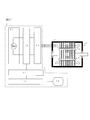
- FIG. 1 is a diagram showing an example of an insulation inspection apparatus for inspecting a rotating electrical machine by an interphase insulation partial discharge inspection method according to the present invention.
- the insulation inspection apparatus 1 includes an impulse power supply unit 11, a partial discharge measuring instrument 12, a wiring switching mechanism 13, a data collection storage unit 14, a pass / fail determination processing unit 15, and a display unit 16.
- Reference numeral 2 denotes an inverter-driven low-voltage rotating electrical machine to be inspected, which will be simply referred to as a motor below.
- the motor 2 includes a stator coil 5 that generates a rotating magnetic field, a stator 4 that houses the stator coil 5, and a rotor 6 that rotates with the rotating magnetic field.
- a secondary winding is inserted into the rotor 6, and when the motor is a permanent magnet synchronous motor, a magnet is inserted at a position 8.
- the rotor 6 and the stator 4 of the motor 2 are housed in a frame 7.
- FIG. 1 shows the motor 2 with the rotor 6 inserted, since the object to be inspected is the stator coil 5, the inspection can be performed even when the rotor 6 is not inserted.
- the impulse power supply 11 is connected to the wiring switching mechanism 13 via the partial discharge measuring instrument 12.
- the motor 2 is connected to the wiring switching mechanism 13.
- the wiring switching mechanism 13 distributes the output wiring of the partial discharge measuring instrument 12 into the three phases U, V, and W of the motor 2.
- the data collection storage unit 14 records the magnitude of the test voltage applied to the motor 2 by the impulse power supply 11 and the partial discharge pulse signal measured by the partial discharge measuring instrument 12.
- a partial discharge measurement method for example, a well-known method described in Non-Patent Documents 1 and 2 or Japanese Patent Application Laid-Open No. 2007-232517 is used.
- the acceptance / rejection determination processing unit 15 determines that the partial discharge pulse signal is not generated at the specified test voltage, and determines that the partial discharge pulse signal has been generated.
- the display unit 16 is a liquid crystal display or a CRT, and displays a pass / fail judgment result of the motor 2 insulation test.
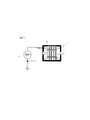
- Fig. 2 shows an example of a test circuit for motor phase insulation inspection.
- an impulse voltage 21 is applied between the phases to be inspected.
- the other phase and the motor frame 7 are set to a floating potential.
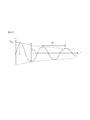
- Fig. 3 shows the impulse voltage waveform used for the interphase insulation inspection of Fig. 1.
- an impulse voltage that first rises at a voltage rise time tr and then oscillates damped is used.
- the voltage applied between the rotating electrical machine winding turns can be suppressed by using such a voltage waveform.
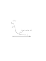
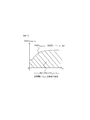
- FIG. 4 shows the winding turn-to-turn voltage Vcoil when the impulse voltage rise time tr is changed.
- the winding turn voltage V coil is smaller than the partial discharge start voltage PDIV, and the occurrence of partial discharge between the motor winding turns can be suppressed. That is, by using the voltage rise time tr and the impulse voltage having the peak value V max included in the hatched region, it is possible to suppress the occurrence of partial discharge between the motor winding turns. Therefore, Tr and V max must satisfy the following formula (1).
- V max ⁇ PDIV (motor-tt) PDIV / ( ⁇ coil / tr) (1)
- the rise time tr of the impulse voltage may be lengthened.
- FIG. 6 shows an impulse test voltage waveform when the rise time tr of the impulse voltage is increased in FIG.
- the rise time tr of the impulse voltage has an upper limit.
- the rise time tr needs to satisfy the following expression (3).
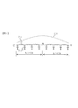
- FIG. 7 shows an example of generation of a standing wave when a high frequency vibration voltage is applied to the motor winding.
- Both the U phase and the V phase are composed of X coils.
- the motor winding is represented by a distributed constant circuit in which an inductance 71 of the coil and a capacitance 72 between the coil and the core (ground) are connected.
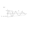
- Fig. 8 shows the test voltage waveform when the impulse voltage oscillates damped.
- an impulse power source can instantaneously generate energy, but cannot permanently generate a vibration wave. That is, unless the energy is continuously supplied from the outside, the voltage peak value attenuates as shown in FIG. For this reason, if the frequency f of the damped vibration is too low, there arises a problem that the negative side peak voltage is lowered.
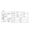
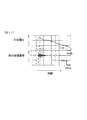
- FIG. 9 shows the measurement result in the case of the above. Also shown in FIG. 9 are PDIVs of insulating materials used for motor winding turns, interphase, and ground insulation.
- the partial discharge start voltage PDIV for interphase insulation is 3.6 kVp-p. This is twice as high as 1.8 kVo-p of the partial discharge start voltage PDIV of the insulating material used for the interphase insulation, which indicates that the partial discharge of the interphase insulation of the motor can be correctly measured.
- the interphase insulation partial discharge start voltage PDIV is 2.3 kVp-p
- the original interphase insulation partial discharge start voltage PDIV (1.8 kVo-p (3 It is measured lower than 6 kVp-p)).
- FIG. 10 shows an example of a voltage waveform and a partial discharge signal waveform when a partial discharge of motor phase insulation is measured using a conventional steep impulse voltage.
- the partial discharge pulse signal 91 is generated only at the steep voltage rising portion.
- the polarity of the partial discharge pulse signal is reversed within the range of the steep voltage rise, the voltage between winding turns suddenly increases due to a steep voltage change, and then immediately decreases. The cause suggests the possibility of such a waveform. That is, there is a possibility that partial discharge has occurred between winding turns.
- partial discharge is not generated between winding turns, It is possible to inspect the partial discharge characteristics of the interphase insulation by accurately applying a test voltage to the interphase insulation.
Landscapes
- Physics & Mathematics (AREA)
- General Physics & Mathematics (AREA)
- Engineering & Computer Science (AREA)
- Power Engineering (AREA)
- Testing Relating To Insulation (AREA)
- Tests Of Circuit Breakers, Generators, And Electric Motors (AREA)
- Testing Of Short-Circuits, Discontinuities, Leakage, Or Incorrect Line Connections (AREA)
Abstract
Description
tr>(τcoil・Vmax)/(PDIV) …(A1)
本発明の第2の態様によると、第1の態様のインバータ駆動回転電機において、インパルス電圧は振動周波数fを有する振動電圧であり、電圧立ち上がり時間trが次式(A2)を満足するように設定されているのが好ましい。
tr≦1/(4f) …(A2)
本発明の第3の態様によると、第2の態様のインバータ駆動回転電機において、インパルス電圧は振動周波数fおよび時定数Kを有する減衰振動電圧であり、振動周波数fは次式(A3)を満足するように設定されていることが好ましい
-1/(2K・ln((Vtest/Vmax)-1)≦f≦1/(2√(L・C)) …(A3)
本発明の第4の態様によると、第1乃至3の態様のいずれか一のインバータ駆動回転電機において、定格電圧が700Vrms以下に設定されているのが好ましい。
本発明の第5の態様によると、相間絶縁部分放電検査方法は、次式(A1)を満足する電圧立ち上がり時間trのインパルス電圧を回転電機に印加する工程と、部分放電が発生したか否かを確認する工程と、部分放電の発生が確認されない場合に回転電機の相間絶縁性能を合格と判定する工程と、を有する。ただし、τcoilは回転電機巻線の1コイルのサージ伝播時間、PDIVは巻線ターン間の部分放電開始電圧、Vmaxは相間絶縁の部分放電試験電圧のピークである。
tr>(τcoil・Vmax)/(PDIV) …(A1)
本発明の第6の態様によると、第5の態様の相間絶縁部分放電検査方法において、インパルス電圧は振動周波数fを有する振動電圧であり、電圧立ち上がり時間trが次式(A2)を満足するように設定されていることが好ましい。
tr≦1/(4f) …(A2)
本発明の第7の態様によると、第6の態様の相間絶縁部分放電検査方法において、インパルス電圧は振動周波数fおよび時定数Kを有する減衰振動電圧であり、振動周波数fは次式(A3)を満足するように設定されていることが好ましい。
-1/(2K・ln((Vtest/Vmax)-1)≦f≦1/(2√(L・C)) …(A3)
本発明の第8の態様によると、相間絶縁部分放電検査装置は、次式(A1)を満足する電圧立ち上がり時間trのインパルス電圧を回転電機に印加するインパルス電源と、インパルス電圧を回転電機に印加したときに発生する部分放電を計測する計測部と、計測部で部分放電が計測されない場合に相間絶縁性能合格と判定する判定部と、を備える。ただし、τcoilは回転電機巻線の1コイルのサージ伝播時間、PDIVは巻線ターン間の部分放電開始電圧、Vmaxは相間絶縁の部分放電試験電圧のピークである。
tr>(τcoil・Vmax)/(PDIV) …(A1)
本発明の第9の態様によると、第8の態様の相間絶縁部分放電検査装置において、インパルス電圧は振動周波数fを有する振動電圧であり、電圧立ち上がり時間trが次式(A2)を満足するように設定されていることが好ましい。
tr≦1/(4f) …(A2)
本発明の第10の態様によると、第9の態様の相間絶縁部分放電検査装置において、インパルス電圧は振動周波数fおよび時定数Kを有する減衰振動電圧であり、振動周波数fは次式(A3)を満足するように設定されていることが好ましい。
-1/(2K・ln((Vtest/Vmax)-1)≦f≦1/(2√(L・C)) …(A3)
Vmax<PDIV(motor-t-t)=PDIV/(τcoil/tr) …(1)
tr>(τcoil・Vmax)/(PDIV) …(2)
tr≦1/(4f) …(3)
λ/2>2X …(4)
v=f・λ=1/√(l・c) …(5)
f<1/(4X√(l・c)) …(6)
L=2X・l …(7)
C=2X・c …(8)
f<1/(2√(L・C)) …(9)
Vmax ・exp(-(1/2f)/K) …(10)
Vmax{1+exp(-(1/2f)/K)} …(11)
Vmax{1+exp(-(1/2f)/K)}≧Vtest …(12)
-1/(2K・ln((Vtest/Vmax)-1)≦f …(13)
Claims (10)
- 次式(A1)を満足する電圧立ち上がり時間trおよび電圧ピークVmaxを有するインパルス電圧が印加された場合でも部分放電が発生しないように、回転電機巻線の1コイルのサージ伝播時間τcoilおよび巻線ターン間の部分放電開始電圧PDIVが設定されているインバータ駆動回転電機。
tr>(τcoil・Vmax)/(PDIV) …(A1) - 請求項1に記載のインバータ駆動回転電機において、
前記インパルス電圧は振動周波数fを有する振動電圧であり、
前記電圧立ち上がり時間trが次式(A2)を満足するように設定されていることを特徴とするインバータ駆動回転電機。
tr≦1/(4f) …(A2) - 請求項2に記載のインバータ駆動回転電機において、
前記インパルス電圧は振動周波数fおよび時定数Kを有する減衰振動電圧であり、
前記振動周波数fは次式(A3)を満足するように設定されていることを特徴とするインバータ駆動回転電機。
-1/(2K・ln((Vtest/Vmax)-1)≦f≦1/(2√(L・C))…(A3) - 請求項1乃至3のいずれか一項に記載のインバータ駆動回転電機において、
定格電圧が700Vrms以下に設定されていることを特徴とするインバータ駆動回転電機。 - 次式(A1)を満足する電圧立ち上がり時間trのインパルス電圧を回転電機に印加する工程と、
部分放電が発生したか否かを確認する工程と、
部分放電の発生が確認されない場合に前記回転電機の相間絶縁性能を合格と判定する工程と、を有するインバータ駆動回転電機の相間絶縁部分放電検査方法。ただし、τcoilは回転電機巻線の1コイルのサージ伝播時間、PDIVは巻線ターン間の部分放電開始電圧、Vmaxは相間絶縁の部分放電試験電圧のピークである。
tr>(τcoil・Vmax)/(PDIV) …(A1) - 請求項5に記載のインバータ駆動回転電機の相間絶縁部分放電検査方法において、
前記インパルス電圧は振動周波数fを有する振動電圧であり、
前記電圧立ち上がり時間trが次式(A2)を満足するように設定されていることを特徴とするインバータ駆動回転電機の相間絶縁部分放電検査方法。
tr≦1/(4f) …(A2) - 請求項6に記載のインバータ駆動回転電機の相間絶縁部分放電検査方法において、
前記インパルス電圧は振動周波数fおよび時定数Kを有する減衰振動電圧であり、
前記振動周波数fは次式(A3)を満足するように設定されていることを特徴とするインバータ駆動回転電機の相間絶縁部分放電検査方法。
-1/(2K・ln((Vtest/Vmax)-1)≦f≦1/(2√(L・C))…(A3) - 次式(A1)を満足する電圧立ち上がり時間trのインパルス電圧を回転電機に印加するインパルス電源と、
前記インパルス電圧を回転電機に印加したときに発生する部分放電を計測する計測部と、
前記計測部で部分放電が計測されない場合に相間絶縁性能合格と判定する判定部と、を備えたインバータ駆動回転電機の相間絶縁部分放電検査装置。ただし、τcoilは回転電機巻線の1コイルのサージ伝播時間、PDIVは巻線ターン間の部分放電開始電圧、Vmaxは相間絶縁の部分放電試験電圧のピークである。
tr>(τcoil・Vmax)/(PDIV) …(A1) - 請求項8に記載のインバータ駆動回転電機の相間絶縁部分放電検査装置において、
前記インパルス電圧は振動周波数fを有する振動電圧であり、
前記電圧立ち上がり時間trが次式(A2)を満足するように設定されていることを特徴とするインバータ駆動回転電機の相間絶縁部分放電検査装置。
tr≦1/(4f) …(A2) - 請求項9に記載のインバータ駆動回転電機の相間絶縁部分放電検査装置において、
前記インパルス電圧は振動周波数fおよび時定数Kを有する減衰振動電圧であり、
前記振動周波数fは次式(A3)を満足するように設定されていることを特徴とするインバータ駆動回転電機の相間絶縁部分放電検査装置。
-1/(2K・ln((Vtest/Vmax)-1)≦f≦1/(2√(L・C))…(A3)
Priority Applications (5)
| Application Number | Priority Date | Filing Date | Title |
|---|---|---|---|
| PCT/JP2011/060167 WO2012147163A1 (ja) | 2011-04-26 | 2011-04-26 | インバータ駆動回転電機、相間絶縁部分放電検査方法および相間絶縁部分放電検査装置 |
| CN201180070406.1A CN103492889B (zh) | 2011-04-26 | 2011-04-26 | 相间绝缘部分放电检查方法和相间绝缘部分放电检查装置 |
| US14/112,828 US10024896B2 (en) | 2011-04-26 | 2011-04-26 | Inverter-driven rotary electric machine, phase-to-phase insulation partial discharge inspection method and phase-to-phase insulation partial discharge inspection apparatus |
| DE112011105190.5T DE112011105190T5 (de) | 2011-04-26 | 2011-04-26 | Durch einen Wechselrichter angesteuerte rotierende elektrische Maschine, ein Phase-zu-Phase-Isolierungs-Teilentladungs-Prüfverfahren und eine Phase-zu-Phase-Isolierungs-Teilentladungs-Prüfvorrichtung |
| JP2013511823A JP5677690B2 (ja) | 2011-04-26 | 2011-04-26 | 相間絶縁部分放電検査方法および相間絶縁部分放電検査装置 |
Applications Claiming Priority (1)
| Application Number | Priority Date | Filing Date | Title |
|---|---|---|---|
| PCT/JP2011/060167 WO2012147163A1 (ja) | 2011-04-26 | 2011-04-26 | インバータ駆動回転電機、相間絶縁部分放電検査方法および相間絶縁部分放電検査装置 |
Publications (1)
| Publication Number | Publication Date |
|---|---|
| WO2012147163A1 true WO2012147163A1 (ja) | 2012-11-01 |
Family
ID=47071705
Family Applications (1)
| Application Number | Title | Priority Date | Filing Date |
|---|---|---|---|
| PCT/JP2011/060167 Ceased WO2012147163A1 (ja) | 2011-04-26 | 2011-04-26 | インバータ駆動回転電機、相間絶縁部分放電検査方法および相間絶縁部分放電検査装置 |
Country Status (5)
| Country | Link |
|---|---|
| US (1) | US10024896B2 (ja) |
| JP (1) | JP5677690B2 (ja) |
| CN (1) | CN103492889B (ja) |
| DE (1) | DE112011105190T5 (ja) |
| WO (1) | WO2012147163A1 (ja) |
Cited By (1)
| Publication number | Priority date | Publication date | Assignee | Title |
|---|---|---|---|---|
| WO2024057418A1 (ja) | 2022-09-13 | 2024-03-21 | 日新パルス電子株式会社 | インバータパルス絶縁試験装置 |
Families Citing this family (12)
| Publication number | Priority date | Publication date | Assignee | Title |
|---|---|---|---|---|
| JPWO2012147162A1 (ja) * | 2011-04-26 | 2014-07-28 | 日立オートモティブシステムズ株式会社 | インバータ駆動回転電機、絶縁検査方法および絶縁検査装置 |
| US9797955B2 (en) | 2012-11-29 | 2017-10-24 | Mitsubishi Electric Corporation | Insulation inspection device for motors and insulation inspection method for motors |
| US20170030957A1 (en) * | 2015-07-31 | 2017-02-02 | Aktiebolaget Skf | Partial discharge detection relay matrix for multiple lead analysis |
| CN109946487B (zh) * | 2019-03-14 | 2021-02-26 | 安徽天兵电子科技股份有限公司 | 一种tr组件的旋转式检测工装 |
| JP7255322B2 (ja) * | 2019-04-03 | 2023-04-11 | 株式会社デンソー | 絶縁検査装置および絶縁検査方法 |
| CN111175621B (zh) * | 2020-01-07 | 2023-03-10 | 岭东核电有限公司 | 核电站中、高压旋转电机绝缘缺陷检测方法、系统及设备 |
| CN113189459B (zh) * | 2021-04-29 | 2021-11-02 | 四川大学 | 一种基于三曲线法的驱动电机绝缘薄弱点检测方法 |
| DE102021124670B3 (de) * | 2021-09-23 | 2023-01-26 | Audi Aktiengesellschaft | Prüfvorrichtung zum Lokalisieren einer Teilentladung in oder an einer elektrischen Komponente sowie Verfahren zum Lokalisieren der Teilentladung |
| CN115792315A (zh) * | 2022-11-09 | 2023-03-14 | 格至达智能科技(江苏)有限公司 | 匝间测试标准波形选取方法 |
| CN116566095B (zh) * | 2023-03-22 | 2026-07-17 | 东方电气(德阳)电动机技术有限责任公司 | 一种变频电机定子线圈柔性绝缘结构和防晕结构 |
| CN119199424B (zh) * | 2024-10-08 | 2025-05-16 | 国网青海省电力公司海北供电公司 | 多元应力下电缆接头局部放电检测方法 |
| CN119087300A (zh) * | 2024-11-07 | 2024-12-06 | 三峡金沙江云川水电开发有限公司 | 一种干式变压器匝间绝缘故障检测方法及系统 |
Citations (2)
| Publication number | Priority date | Publication date | Assignee | Title |
|---|---|---|---|---|
| JPH09298853A (ja) * | 1996-05-02 | 1997-11-18 | Toshiba Corp | 電機巻線 |
| JP2010166813A (ja) * | 2010-04-23 | 2010-07-29 | Hitachi Industrial Equipment Systems Co Ltd | 電力変換装置、モータ及びモータ駆動システム |
Family Cites Families (6)
| Publication number | Priority date | Publication date | Assignee | Title |
|---|---|---|---|---|
| JP2714031B2 (ja) * | 1988-09-14 | 1998-02-16 | 株式会社東芝 | コイルの劣化診断方法 |
| DE10060243A1 (de) | 2000-12-05 | 2002-06-06 | Berton Farhad | Zerstörungsfreies Verfahren zur Diagnose des Isolationssystems der elektrischen Maschinen durch die Anwendung der Stoßspannungs- und Teilentladungsmessung |
| JP4557616B2 (ja) * | 2004-07-02 | 2010-10-06 | 株式会社日立産機システム | 電力変換装置 |
| JP4418320B2 (ja) * | 2004-07-28 | 2010-02-17 | 株式会社日立産機システム | モータ巻線ターン間部分放電計測方法 |
| JP4904989B2 (ja) * | 2006-08-24 | 2012-03-28 | 株式会社日立製作所 | 回転電機,巻線機,回転電機システム,ハイブリッド自動車,燃料電池自動車、及び電気自動車 |
| JP2009115505A (ja) | 2007-11-02 | 2009-05-28 | Mitsubishi Electric Corp | 巻線の検査装置及び検査方法 |
-
2011
- 2011-04-26 US US14/112,828 patent/US10024896B2/en active Active
- 2011-04-26 JP JP2013511823A patent/JP5677690B2/ja active Active
- 2011-04-26 CN CN201180070406.1A patent/CN103492889B/zh active Active
- 2011-04-26 WO PCT/JP2011/060167 patent/WO2012147163A1/ja not_active Ceased
- 2011-04-26 DE DE112011105190.5T patent/DE112011105190T5/de active Pending
Patent Citations (2)
| Publication number | Priority date | Publication date | Assignee | Title |
|---|---|---|---|---|
| JPH09298853A (ja) * | 1996-05-02 | 1997-11-18 | Toshiba Corp | 電機巻線 |
| JP2010166813A (ja) * | 2010-04-23 | 2010-07-29 | Hitachi Industrial Equipment Systems Co Ltd | 電力変換装置、モータ及びモータ駆動システム |
Cited By (1)
| Publication number | Priority date | Publication date | Assignee | Title |
|---|---|---|---|---|
| WO2024057418A1 (ja) | 2022-09-13 | 2024-03-21 | 日新パルス電子株式会社 | インバータパルス絶縁試験装置 |
Also Published As
| Publication number | Publication date |
|---|---|
| CN103492889A (zh) | 2014-01-01 |
| DE112011105190T5 (de) | 2014-01-23 |
| JPWO2012147163A1 (ja) | 2014-07-28 |
| JP5677690B2 (ja) | 2015-02-25 |
| CN103492889B (zh) | 2015-11-25 |
| US10024896B2 (en) | 2018-07-17 |
| US20140180617A1 (en) | 2014-06-26 |
Similar Documents
| Publication | Publication Date | Title |
|---|---|---|
| JP5677690B2 (ja) | 相間絶縁部分放電検査方法および相間絶縁部分放電検査装置 | |
| JP4418320B2 (ja) | モータ巻線ターン間部分放電計測方法 | |
| Zhang et al. | A novel online stator ground-wall insulation monitoring scheme for inverter-fed AC motors | |
| Mirafzal et al. | Universal induction motor model with low-to-high frequency-response characteristics | |
| JP5882019B2 (ja) | インバータ駆動回転電機の試験方法、及び回転電機の試験方法 | |
| JP5663318B2 (ja) | インバータ駆動回転電機の部分放電試験法 | |
| WO2012147162A1 (ja) | インバータ駆動回転電機、絶縁検査方法および絶縁検査装置 | |
| Zheng et al. | An improved online stator insulation monitoring method based on common-mode impedance spectrum considering the effect of aging position | |
| JP5134602B2 (ja) | インバータ駆動モータの絶縁設計方法及び製造方法 | |
| Mirafzal et al. | A failure mode for PWM inverter-fed AC motors due to the antiresonance phenomenon | |
| Zoeller et al. | Inverter-fed drive stator insulation monitoring based on reflection phenomena stimulated by voltage step excitation | |
| JP2002365326A (ja) | 回転電機の絶縁診断方法および絶縁診断装置 | |
| JP2011117844A (ja) | 絶縁診断装置 | |
| Zheng et al. | Comparative study of neutral-voltage-based and leakage-current-based online condition monitoring methods for stator insulation of inverter-fed machines | |
| Ruiz-Sarrio et al. | Broadband technique analysis for insulation fault detection and condition monitoring in rotating electrical machines | |
| Kang et al. | The influence of the rotor on surge pd testing of low voltage AC motor stator windings | |
| JP2013124913A (ja) | 部分放電測定方法および回転電機の製造方法 | |
| Zheng et al. | An improved broadband common-mode electrical machine model for online condition monitoring of stator insulation degradation | |
| JP5414376B2 (ja) | 部分放電検査方法および回転電機 | |
| JP6110783B2 (ja) | 電動機巻線の繰り返しインパルス部分放電試験方法およびそのための装置 | |
| JP2020169986A (ja) | 絶縁検査装置および絶縁検査方法 | |
| Pan et al. | Double-ring high-frequency common-mode switching oscillation current sensor for inverter-fed machine winding insulation monitoring | |
| Drif et al. | The use of the stator instantaneous complex apparent impedance signature analysis for discriminating stator winding faults and supply voltage unbalance in three-phase induction motors | |
| JP6314875B2 (ja) | インバータ駆動モータの検査方法 | |
| Montero et al. | Comprehensive Classification of Motor Winding Insulation Aging Scenarios Based on Transient Current Oscillations |
Legal Events
| Date | Code | Title | Description |
|---|---|---|---|
| 121 | Ep: the epo has been informed by wipo that ep was designated in this application |
Ref document number: 11864421 Country of ref document: EP Kind code of ref document: A1 |
|
| ENP | Entry into the national phase |
Ref document number: 2013511823 Country of ref document: JP Kind code of ref document: A |
|
| WWE | Wipo information: entry into national phase |
Ref document number: 1120111051905 Country of ref document: DE Ref document number: 112011105190 Country of ref document: DE |
|
| WWE | Wipo information: entry into national phase |
Ref document number: 14112828 Country of ref document: US |
|
| 122 | Ep: pct application non-entry in european phase |
Ref document number: 11864421 Country of ref document: EP Kind code of ref document: A1 |