WO2012147154A1 - ワイヤーハーネスの製造方法 - Google Patents
ワイヤーハーネスの製造方法 Download PDFInfo
- Publication number
- WO2012147154A1 WO2012147154A1 PCT/JP2011/060115 JP2011060115W WO2012147154A1 WO 2012147154 A1 WO2012147154 A1 WO 2012147154A1 JP 2011060115 W JP2011060115 W JP 2011060115W WO 2012147154 A1 WO2012147154 A1 WO 2012147154A1
- Authority
- WO
- WIPO (PCT)
- Prior art keywords
- sheet
- peripheral surface
- outer peripheral
- jig
- electric wire
- Prior art date
- Legal status (The legal status is an assumption and is not a legal conclusion. Google has not performed a legal analysis and makes no representation as to the accuracy of the status listed.)
- Ceased
Links
Images



Classifications
-
- H—ELECTRICITY
- H01—ELECTRIC ELEMENTS
- H01B—CABLES; CONDUCTORS; INSULATORS; SELECTION OF MATERIALS FOR THEIR CONDUCTIVE, INSULATING OR DIELECTRIC PROPERTIES
- H01B13/00—Apparatus or processes specially adapted for manufacturing conductors or cables
- H01B13/012—Apparatus or processes specially adapted for manufacturing conductors or cables for manufacturing wire harnesses
-
- H—ELECTRICITY
- H02—GENERATION; CONVERSION OR DISTRIBUTION OF ELECTRIC POWER
- H02G—INSTALLATION OF ELECTRIC CABLES OR LINES, OR OF COMBINED OPTICAL AND ELECTRIC CABLES OR LINES
- H02G3/00—Installations of electric cables or lines or protective tubing therefor in or on buildings, equivalent structures or vehicles
- H02G3/02—Details
- H02G3/04—Protective tubing or conduits, e.g. cable ladders or cable troughs
- H02G3/0462—Tubings, i.e. having a closed section
- H02G3/0487—Tubings, i.e. having a closed section with a non-circular cross-section
-
- B—PERFORMING OPERATIONS; TRANSPORTING
- B60—VEHICLES IN GENERAL
- B60R—VEHICLES, VEHICLE FITTINGS, OR VEHICLE PARTS, NOT OTHERWISE PROVIDED FOR
- B60R16/00—Electric or fluid circuits specially adapted for vehicles and not otherwise provided for; Arrangement of elements of electric or fluid circuits specially adapted for vehicles and not otherwise provided for
- B60R16/02—Electric or fluid circuits specially adapted for vehicles and not otherwise provided for; Arrangement of elements of electric or fluid circuits specially adapted for vehicles and not otherwise provided for electric constitutive elements
- B60R16/0207—Wire harnesses
- B60R16/0215—Protecting, fastening and routing means therefor
-
- Y—GENERAL TAGGING OF NEW TECHNOLOGICAL DEVELOPMENTS; GENERAL TAGGING OF CROSS-SECTIONAL TECHNOLOGIES SPANNING OVER SEVERAL SECTIONS OF THE IPC; TECHNICAL SUBJECTS COVERED BY FORMER USPC CROSS-REFERENCE ART COLLECTIONS [XRACs] AND DIGESTS
- Y10—TECHNICAL SUBJECTS COVERED BY FORMER USPC
- Y10T—TECHNICAL SUBJECTS COVERED BY FORMER US CLASSIFICATION
- Y10T29/00—Metal working
- Y10T29/49—Method of mechanical manufacture
- Y10T29/49002—Electrical device making
- Y10T29/49117—Conductor or circuit manufacturing
Definitions
- the present invention relates to a method of manufacturing a wire harness, and more particularly, to a method of manufacturing a wire harness provided with a protector that protects an electric wire (single electric wire and a plurality of electric wire groups) constituting the wire harness. .
- a wire harness for connecting electrical equipment and electronic equipment to each other is routed.
- the wire harness is formed by bundling a predetermined type of electric wire into a predetermined shape.
- a protector may be attached to a predetermined portion of the electric wire constituting the wire harness in order to prevent damage due to an external load or the like.
- protectors There are various types of protectors.
- a molded product having a hollow shell shape is widely used.
- the configuration to which the protector of the molded product is applied it is possible to prevent a load from being applied to the electric wire from the outside by accommodating the electric wire in the space inside the protector. For this reason, damage of an electric wire etc. can be prevented.
- the configuration to which the protector for a molded product is applied has the following problems.
- Patent Document 2 As a configuration in which the welded portion does not protrude from the outer peripheral surface of the electric wire group, for example, a configuration described in Japanese Patent Laid-Open No. 9 (1997) -298015 of Patent Document 2 has been proposed.
- a group of electric wires constituting a wire harness is covered with a flexible sheet, and both side portions of the flexible sheet are superimposed on the outer peripheral surface of the group of electric wires.
- An adhesive for melting is applied, and in this state, the electric wire group and the flexible sheet are pressed while being heated by a heating press.
- the overlapped portion of the flexible sheet is pressurized and heated, the overlapped portion is bonded by an adhesive for hot melt.
- each electric wire constituting the wire harness generally has a configuration in which a conductive wire is covered with a covering material, and the covering material is formed of a resin composition having thermoplasticity. For this reason, when an electric wire group is heated, the coating
- Patent Document 2 is not a configuration in which only the overlapping portion of the flexible sheet is directly pressed by the pressing die of the heating press, but the side portion of the flexible sheet that forms the overlapping portion.
- One of these is indirectly pressurized through a group of wires. For this reason, if the electric wire group is deformed at the time of pressurization, there is a possibility that sufficient pressurizing force may not be applied to the overlapping portion of the flexible sheet. For this reason, the overlapping portion of the flexible sheet is not sufficiently bonded, and the bonding strength may be reduced. If the applied pressure is increased in order to improve the bonding strength, the applied pressure applied to the electric wire group also increases, which may damage the electric wire group.
- the pressure applied to the overlapping portion of the flexible sheet during pressurization may be affected by the deformation mode of the wire group, but it is possible to control the deformation of the wire group to be uniform. Since it is difficult, the pressure applied to the overlapping portion of the flexible sheet may be non-uniform. As a result, there is a possibility that the bonding strength of the overlapped portion is not uniform.
- the problem to be solved by the present invention is a wire that can reduce the size of a protector mounted around an electric wire (including both a single electric wire and a bundle of plural electric wires) for protection.
- a method for manufacturing a wire harness winds a sheet-like member around an outer peripheral surface of a predetermined portion of an electric wire (including a single electric wire and an electric wire bundle including a plurality of electric wires). And overlapping the both sides of the sheet-like member on the outer peripheral surface of the predetermined portion of the electric wire, and the outer peripheral surface of the predetermined portion of the electric wire and the overlapping portion of the sheet-like member Including a step of disposing a jig between the peripheral surface and pressurizing and welding at least a part of the overlapped portion of the sheet-like member with a pressure member of a welding machine. It is what.
- the “outer peripheral surface of the electric wire” refers to the outer peripheral surface of the member provided on the outermost side of the single electric wire (generally, the outer peripheral surface of the covering material). If the wire bundle is made of a wire bundle, the outer peripheral surface of the object when the wire bundle is regarded as a single object (however, the fine irregularities formed by each wire and the gaps formed between the wires are ignored. The outer surface of the modeled object).
- An ultrasonic welding machine can be applied to the welding machine, and in this case, a member made of a material capable of ultrasonic welding can be applied to the sheet-like member. And the structure welded by applying an ultrasonic vibration, pressing at least one part of the said overlapped part of the said sheet-like member is applicable.
- the jig may be a flat plate having a predetermined length in the axial direction of the electric wire or a substantially rod-shaped member having a cross-sectional arc shape along the shape of the outer peripheral surface of the electric wire.
- the jig is disposed in advance on the outer peripheral surface of the predetermined portion of the electric wire before the sheet-shaped member is wound around the predetermined portion of the electric wire, and both sides of the sheet-shaped member are cured on the side.
- the structure on which it overlaps on the outer peripheral surface of a tool may be sufficient.
- the jig is configured such that the outer peripheral surface of the predetermined portion of the electric wire and the overlapped portion of the sheet-like member The structure inserted between these may be sufficient.
- the step of joining both side portions of the sheet-like member at least a part of both side portions of the sheet-like member is a pressure member (welding of the welding machine). If the machine is an ultrasonic welder, it is sandwiched between the horn of the ultrasonic welder and the jig and pressed. For this reason, a predetermined pressurizing force can be applied to a predetermined portion of the sheet-like member (that is, a portion serving as a joint portion).
- the applied pressure applied to a sheet-like member can be enlarged, and the improvement of the joint strength in a junction part can be aimed at. Furthermore, since it becomes easy to control the applied pressure, when joining a plurality of locations sequentially, a uniform applied pressure can be applied to all locations, and the joining strength can be made uniform. Therefore, the quality of the wire harness is stabilized and quality control becomes easy.
- the present invention it is possible to prevent the joint strength from being lowered or improve the joint strength at the joint portion while preventing the joint portion of the material constituting the protector from projecting to the outside.
- FIG. 1 is a diagram schematically showing the configuration of a wire harness 1 manufactured using the method for manufacturing a wire harness according to an embodiment of the present invention.
- FIG. 1A is an external perspective view showing a part extracted
- FIG. 1B is a cross-sectional view taken along the line AA in FIG. FIG.
- the wire harness manufactured using the method for manufacturing the wire harness according to the embodiment of the present invention may be referred to as “the present wire harness”.
- the wire harness 1 as a whole has a configuration in which a predetermined type and a predetermined number of electric wires 11 are bundled to form an electric wire bundle 12, and the electric wire bundle 12 is formed in a predetermined shape. Predetermined connectors are attached to the end portions of the electric wires 11 constituting the electric wire bundle 12 of the wire harness 1 (not shown). And as shown to FIG. 1 (a), (b), the protector 13 is provided in the outer peripheral surface of the predetermined part of the wire bundle 12 of this wire harness 1. FIG. In addition, although the protector 13 is provided in the part which wants to protect among the wire bundles 12 of this wire harness 1, the structure provided in a part of the wire bundle 12 of this wire harness 1 may be sufficient, and it is provided in the whole. It may be a configuration.
- the protector 13 is formed by a sheet-like member 14 made of a material capable of ultrasonic welding (that is, a material having thermoplasticity).
- a material capable of ultrasonic welding that is, a material having thermoplasticity.
- sheets, nonwoven fabrics, foams and the like formed from various thermoplastic resin compositions can be applied.
- the protector 13 has a configuration in which a sheet-like member 14 is wound around the outer peripheral surface of the wire bundle 12. In other words, the protector 13 is formed by winding the sheet-like member 14 around the outer peripheral surface of the wire bundle 12.
- the protector 13 is formed with an overlapping portion 131.
- the overlapping portion 131 is a portion where one side portion 141 and the other side portion 142 of the sheet-like member 14 overlap on the outer peripheral surface of the wire bundle 12.
- the overlapping portion 131 is disposed such that one side portion 141 of the sheet-like member 14 is along the outer peripheral surface of the wire bundle 12, and the other side portion 142 is outside the one side portion 141.
- FIG. 1A shows a configuration in which the joints 132 are formed at a predetermined interval.
- the overlapping portion 131 and the joining portion 132 of the sheet-like member 14 constituting the protector 13 are formed along the outer peripheral surface of the wire bundle 12.
- the overlapping part 131 of the sheet-like member 14 constituting the protector 13 is configured not to protrude outward from the other part of the protector 13. Accordingly, the protector 13 can be reduced in size (particularly, the size and shape of the cut surface cut by a plane substantially perpendicular to the axial direction of the wire bundle 12), and can be easily routed in a narrow space.
- the part which protrudes toward the outer side from the outer peripheral surface of the wire bundle 12 is not formed in the protector 13, handling of this wire harness 1 becomes convenient. That is, if the protector 13 has a portion projecting outward, the projecting portion may be hindered by other objects and hinder routing work, etc. In the wire harness 1, There is no such thing.
- a conventional general ultrasonic welding machine (preferably, an ultrasonic spot welding machine, that is, an ultrasonic welding machine capable of welding an arbitrary specific range) can be applied to the method of manufacturing the wire harness according to the embodiment of the present invention. . Therefore, detailed description is omitted.
- a general ultrasonic welding machine includes an ultrasonic oscillator, an ultrasonic vibrator, and a horn.
- the ultrasonic oscillator can generate an electrical signal having an ultrasonic frequency (for example, AC electricity having an ultrasonic frequency).
- the ultrasonic vibrator is vibrated by an electric signal generated by the ultrasonic oscillator and generates ultrasonic waves.
- the jig 5 is a member that receives pressure from the horn 6 of the ultrasonic welder in the process of joining the both side portions 141 and 142 of the sheet-like member 14. That is, pressure is applied to both side portions 141 and 142 of the sheet-like member 14 by sandwiching both side portions 141 and 142 of the sheet-like member 14 between the horn 6 and the jig 5 of the ultrasonic welder. For this reason, the jig 5 has a strength that does not deform (or hardly deforms) even when it is subjected to the pressure applied by the horn 6 of the ultrasonic welder. However, the thickness dimension is preferably as small as possible. For this reason, the jig 5 is formed of, for example, a metal plate.
- the width dimension of the jig 5 is set based on the dimension and shape of the joint portion 132 of the protector 13. In other words, a portion pressed between the horn and the jig of the ultrasonic welder becomes the joint 132. For this reason, for example, when the size and shape of the joining portion 132 is the joining portion 132 that is the entire portion pressed against the tip of the horn of the ultrasonic welder, the tip of the horn 6 of the ultrasonic welder is used. The size and shape are set larger than the size and shape.
- the jig 5 may have a substantially flat plate shape as shown in FIGS. 2 (a) and 2 (b). However, the jig 5 has a predetermined cross-sectional shape (the cross section here is the longitudinal direction). It may be a structure having a cross section in a plane perpendicular to the surface.
- a configuration having a shape in which the sheet-like member 14 is not greatly deformed can be applied.
- the wire harness 1 is formed to have a substantially circular cross section, the wire harness 1 is formed to have a curved surface having a radius of curvature substantially equal to the radius of the circle formed by the wire bundle 12 of the wire harness 1. Is applicable.
- the length dimension of the jig 5 in the axial direction is set to a dimension larger than the distance from the one end in the axial direction of the wire bundle 12 of the sheet-like member 14 to the joint portion 132.
- the joint 132 can be formed at any position in the axial direction of the wire bundle 12 of the sheet-like member 14. it can.
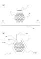
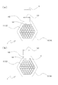
- FIG. 3 to 5 are schematic cross-sectional views schematically showing predetermined steps of the protector manufacturing method according to the embodiment of the present invention.
- FIG. 3A shows a state before the sheet-like member 14 is wound around the wire bundle 12
- FIG. 3B shows the sheet-like member 14 around the wire bundle 12.
- the state where is wound is shown.
- 4A shows a state in which the sheet-like member 14 is wound around the wire bundle 12, and
- FIG. 4B shows the jig 5 between the outer peripheral surface of the wire bundle 12 and the sheet-like member 14.
- FIG. Indicates the inserted state.
- FIG. 5A shows a process of welding one side 141 and the other side 142 of the sheet-like member 14 by an ultrasonic welding machine
- FIG. 5B shows a state where the welding is completed. Show.
- a sheet-like member 14 having a predetermined width dimension is prepared.
- the electric wire bundle 12 is formed in a substantially circular cross section as a whole, the electric wire bundle 12 is formed in a dimension larger than the circular circumferential length formed by the electric wire bundle 12.
- both side portions 141 and 142 of the sheet-like member 14 are on the outer surface of the jig (the surface opposite to the surface facing or contacting the wire bundle 12). It is wound so that it is located above. In other words, both side portions 141 and 142 of the sheet-like member 14 are wound so as to overlap on the outer surface of the jig 5. Thereby, the overlapping part 131 of the sheet-like member 14 is formed on the outer peripheral surface of the jig 5.
- the jig is inserted between the outer peripheral surface of the wire bundle 12 and the inner peripheral surface of the sheet-like member 14.
- FIG. 4A first, the sheet-like member 14 is wound around the outer peripheral surface of the wire bundle 12.
- FIG. 4B a jig is inserted between the outer peripheral surface of the wire bundle 12 and the inner peripheral surface of the sheet-like member 14.
- a portion where both side portions 141, 142 of the sheet-like member 14 wound on the outer peripheral surface of the wire bundle 12 overlap is super
- the horn 6 of the sonic welder is pressed by a predetermined pressure.
- the horn 6 of the ultrasonic welder is pressed to a portion where both side portions 141, 142 of the sheet-like member 14 are overlapped by a predetermined pressure, of the portions where both side portions 141, 142 of the sheet-like member 14 are overlapped
- a predetermined part at least a part of the overlapping part.
- a part of the overlapping part is pressed between the horn 6 and the jig 5 of the ultrasonic welder.
- the outer surface of one side 141 of the sheet-like member 14 and the inner surface of the other side 142 are in contact with each other with a predetermined pressure.
- the ultrasonic welder is operated.
- the ultrasonic vibration is applied to the portion between and pressed by 5) and the vicinity thereof. If it does so, the surface which contacts with a predetermined pressure will be heated by ultrasonic vibration between them.
- the outer surface of one side portion 141 and the inner surface of the other side portion 142 of the sheet-like member 14 have a predetermined pressure.
- the contact surface and the vicinity thereof are heated so as to have a temperature equal to or higher than the melting point of the resin composition.
- the sheet-like member 14 is made of a nonwoven fabric having the above-described configuration, the outer surface of one side 141 of the sheet-like member 14 and the inner surface of the other side 142 contact with a predetermined pressure.
- the surface to be heated and the vicinity thereof are heated so that the temperature is lower than the melting point of the core fiber of the basic fiber and the binder fiber and is equal to or higher than the melting point of the binder material of the core fiber.
- the jig 5 is extracted from between the wire bundle 12 and the sheet-like member 14.
- the protector 13 composed of the sheet-like member 14 is formed at a predetermined position on the outer peripheral surface of the wire bundle 12. And when the protector 13 is formed in the several position of the wire bundle 12, the above process is repeated in the position which requires. Thereby, this wire harness 1 which has a structure as shown in FIG. 1 is manufactured.
- the both side portions 141 and 142 of the sheet-like member 14 are ultrasonically welded. It is sandwiched between the machine horn 6 and the jig 5 and pressurized. As described above, the jig 5 is not deformed or hardly deformed even when the pressure of the horn 6 of the ultrasonic welder is applied. For this reason, a predetermined pressurizing force can be applied to predetermined portions of the side portions 141 and 142 of the sheet-like member 14 (that is, portions that become the joint portions 132).
- the jig 5 when the horn 6 of the ultrasonic welder is pressed to the outside of the side portions 141 and 142, the wire bundle 12 is deformed by the applied pressure, and the applied pressure is relaxed. . For this reason, it is difficult to apply a predetermined pressing force to both side portions 141 and 142, or it is difficult to apply a predetermined pressing force.
- the jig 5 receives the applied pressure of the horn 6 of the ultrasonic welder. And since a part of both side parts 141 and 142 of the sheet-like member 14 are pinched
- a predetermined portion of the overlapped portions of the both side portions 141 and 142 is determined.
- the portion is sandwiched between the horn 6 and the wire bundle 12 of the ultrasonic welder and pressed.
- the pressure applied to the predetermined portion is controlled. (Especially, making it uniform) becomes difficult. For this reason, when joining at a plurality of positions of the overlapped portions of the side portions 141 and 142, the pressure applied to the predetermined portions of the side portions 141 and 142 of the sheet-like member 14 when joining at each position is As a result, the joining strength at each joint 132 becomes non-uniform.
- the manufacturing method of the wire harness concerning embodiment of this invention, although the surface of the electric wire 11 which comprises the electric wire bundle 12 of the wire harness 1 is heated by heat transfer, the temperature rise is small. For this reason, the coating
Landscapes
- Engineering & Computer Science (AREA)
- Architecture (AREA)
- Civil Engineering (AREA)
- Structural Engineering (AREA)
- Manufacturing & Machinery (AREA)
- Details Of Indoor Wiring (AREA)
Abstract
Description
Claims (5)
- 電線の所定の部分の外周面にシート状の部材を巻き付けるととともに、前記シート状の部材の両側部を前記電線の所定の部分の外周面上において重ね合わせる工程と、
前記電線の所定の部分の外周面と前記シート状の部材の前記重ね合わせた部分の内周面との間に治具を配設し、溶着機の加圧部材とにより前記シート状の部材の前記重ね合わせた部分の少なくとも一部を加圧して溶着する工程と、
を含むことを特徴とするワイヤーハーネスの製造方法。 - 前記溶着機は超音波溶着機であり、前記シート状の部材は超音波溶着可能な材料からなり、前記シート状の部材の前記重ね合わせた部分の少なくとも一部を加圧しながら超音波振動を加えることにより溶着することを特徴とする請求項1に記載のワイヤーハーネスの製造方法。
- 前記治具は、前記電線の軸線方向に所定の長さを有する平板あるいは電線の外周面の形状に沿った断面円弧形状をした略棒状の部材であることを特徴とする請求項1または請求項2に記載のワイヤーハーネスの製造方法。
- 前記治具は、前記電線の所定の部分に前記シート状の部材を巻き付ける前に、あらかじめ前記電線の所定の部分の外周面上に配設され、前記シート状の部材は、その両側部が前記治具の外周面上において重ね合わせられることを特徴とする請求項1から請求項3のいずれか1項に記載のワイヤーハーネスの製造方法。
- 前記治具は、前記電線の所定の部分の外周面に前記シート状の部材が巻き付けられた後に、前記電線の所定の部分の外周面と前記シート状の部材の前記重ね合わせられた部分の内周面との間に挿入されることを特徴とする請求項1から請求項3のいずれか1項に記載のワイヤーハーネスの製造方法。
Priority Applications (5)
| Application Number | Priority Date | Filing Date | Title |
|---|---|---|---|
| CA2807624A CA2807624A1 (en) | 2011-04-26 | 2011-04-26 | Wire harness manufacturing method |
| CA2779963A CA2779963A1 (en) | 2011-04-26 | 2011-04-26 | Wire harness manufacturing method |
| PCT/JP2011/060115 WO2012147154A1 (ja) | 2011-04-26 | 2011-04-26 | ワイヤーハーネスの製造方法 |
| US13/583,029 US20140033524A1 (en) | 2011-04-26 | 2011-04-26 | Wire harness manufacturing method |
| CN2011800086168A CN102859614A (zh) | 2011-04-26 | 2011-04-26 | 线束制造方法 |
Applications Claiming Priority (1)
| Application Number | Priority Date | Filing Date | Title |
|---|---|---|---|
| PCT/JP2011/060115 WO2012147154A1 (ja) | 2011-04-26 | 2011-04-26 | ワイヤーハーネスの製造方法 |
Publications (1)
| Publication Number | Publication Date |
|---|---|
| WO2012147154A1 true WO2012147154A1 (ja) | 2012-11-01 |
Family
ID=47071003
Family Applications (1)
| Application Number | Title | Priority Date | Filing Date |
|---|---|---|---|
| PCT/JP2011/060115 Ceased WO2012147154A1 (ja) | 2011-04-26 | 2011-04-26 | ワイヤーハーネスの製造方法 |
Country Status (4)
| Country | Link |
|---|---|
| US (1) | US20140033524A1 (ja) |
| CN (1) | CN102859614A (ja) |
| CA (2) | CA2779963A1 (ja) |
| WO (1) | WO2012147154A1 (ja) |
Cited By (1)
| Publication number | Priority date | Publication date | Assignee | Title |
|---|---|---|---|---|
| JP2023182039A (ja) * | 2022-06-14 | 2023-12-26 | 古河電気工業株式会社 | 接合構造、接合方法、電線用外装体および外装体付きワイヤハーネス |
Families Citing this family (6)
| Publication number | Priority date | Publication date | Assignee | Title |
|---|---|---|---|---|
| CN103417304A (zh) * | 2013-08-08 | 2013-12-04 | 嘉兴君泰医用辅料有限公司 | 一种医用手术巾及其制备方法 |
| JP6644824B2 (ja) * | 2018-04-04 | 2020-02-12 | 矢崎総業株式会社 | 分岐回路体及び電線の分岐方法 |
| JP6691164B2 (ja) * | 2018-04-04 | 2020-04-28 | 矢崎総業株式会社 | 分岐回路体及び電線の分岐方法 |
| JP6852725B2 (ja) | 2018-11-26 | 2021-03-31 | 日立金属株式会社 | ケーブル及びハーネス |
| JP2021151103A (ja) * | 2020-03-19 | 2021-09-27 | 住友電装株式会社 | ワイヤハーネス |
| CN119008119B (zh) * | 2024-10-23 | 2024-12-27 | 南通大地电气股份有限公司 | 一种汽车拉线加工线束定位用穿线装置 |
Citations (6)
| Publication number | Priority date | Publication date | Assignee | Title |
|---|---|---|---|---|
| JPS6248989U (ja) * | 1986-02-13 | 1987-03-26 | ||
| JPH0158217U (ja) * | 1987-10-07 | 1989-04-12 | ||
| JPH02247911A (ja) * | 1989-03-20 | 1990-10-03 | Sumitomo Electric Ind Ltd | Lapシースケーブルの製造方法 |
| JPH0567126U (ja) * | 1992-02-06 | 1993-09-03 | 矢崎総業株式会社 | 電線保護シート |
| JPH09298015A (ja) | 1996-03-06 | 1997-11-18 | Yazaki Corp | フラットハーネス及びその製造方法 |
| JPH117856A (ja) | 1997-06-16 | 1999-01-12 | Sumitomo Wiring Syst Ltd | ワイヤハーネスへの保護材の外装構造 |
Family Cites Families (10)
| Publication number | Priority date | Publication date | Assignee | Title |
|---|---|---|---|---|
| JPH0955130A (ja) * | 1995-08-11 | 1997-02-25 | Sumitomo Wiring Syst Ltd | クランプ保持具およびこれを用いたクランプ取付具 |
| JP3435062B2 (ja) * | 1997-10-03 | 2003-08-11 | 矢崎総業株式会社 | シールド電線の接続構造及び接続方法並びに接続に用いられる超音波ホーン及び接続に用いる接地電線 |
| JP4889160B2 (ja) * | 2001-05-15 | 2012-03-07 | スリーエム イノベイティブ プロパティズ カンパニー | チューブ被覆物品、チューブ被覆装置及びチューブ被覆方法 |
| JP4914539B2 (ja) * | 2001-05-18 | 2012-04-11 | 矢崎総業株式会社 | シールドハーネスの組立方法 |
| JP2003115224A (ja) * | 2001-07-31 | 2003-04-18 | Yazaki Corp | 止水シート巻回治具 |
| JP4118769B2 (ja) * | 2003-09-03 | 2008-07-16 | 矢崎総業株式会社 | ワイヤーハーネスの止水処理方法およびワイヤーハーネス |
| DE202004006151U1 (de) * | 2004-04-19 | 2004-06-17 | Lindner, Michael | Vorrichtung zum Bündeln von Kabelbäumen u.dgl. |
| JP4412126B2 (ja) * | 2004-09-15 | 2010-02-10 | ヤマハ株式会社 | 束線用シート |
| JP4761797B2 (ja) * | 2005-03-14 | 2011-08-31 | 矢崎総業株式会社 | ワイヤハーネスの製造方法 |
| JP2010267412A (ja) * | 2009-05-12 | 2010-11-25 | Autonetworks Technologies Ltd | ワイヤーハーネスの製造方法 |
-
2011
- 2011-04-26 US US13/583,029 patent/US20140033524A1/en not_active Abandoned
- 2011-04-26 CA CA2779963A patent/CA2779963A1/en active Pending
- 2011-04-26 WO PCT/JP2011/060115 patent/WO2012147154A1/ja not_active Ceased
- 2011-04-26 CN CN2011800086168A patent/CN102859614A/zh active Pending
- 2011-04-26 CA CA2807624A patent/CA2807624A1/en not_active Abandoned
Patent Citations (6)
| Publication number | Priority date | Publication date | Assignee | Title |
|---|---|---|---|---|
| JPS6248989U (ja) * | 1986-02-13 | 1987-03-26 | ||
| JPH0158217U (ja) * | 1987-10-07 | 1989-04-12 | ||
| JPH02247911A (ja) * | 1989-03-20 | 1990-10-03 | Sumitomo Electric Ind Ltd | Lapシースケーブルの製造方法 |
| JPH0567126U (ja) * | 1992-02-06 | 1993-09-03 | 矢崎総業株式会社 | 電線保護シート |
| JPH09298015A (ja) | 1996-03-06 | 1997-11-18 | Yazaki Corp | フラットハーネス及びその製造方法 |
| JPH117856A (ja) | 1997-06-16 | 1999-01-12 | Sumitomo Wiring Syst Ltd | ワイヤハーネスへの保護材の外装構造 |
Cited By (1)
| Publication number | Priority date | Publication date | Assignee | Title |
|---|---|---|---|---|
| JP2023182039A (ja) * | 2022-06-14 | 2023-12-26 | 古河電気工業株式会社 | 接合構造、接合方法、電線用外装体および外装体付きワイヤハーネス |
Also Published As
| Publication number | Publication date |
|---|---|
| US20140033524A1 (en) | 2014-02-06 |
| CA2807624A1 (en) | 2012-11-01 |
| CA2779963A1 (en) | 2012-10-26 |
| CN102859614A (zh) | 2013-01-02 |
Similar Documents
| Publication | Publication Date | Title |
|---|---|---|
| JP5446855B2 (ja) | ワイヤーハーネスの製造方法 | |
| JP5920181B2 (ja) | ワイヤーハーネス及びワイヤーハーネスの製造方法 | |
| US20130020125A1 (en) | Wire harness, wire harness manufacturing method | |
| JP5573477B2 (ja) | 電線保護構造部及び電線保護構造部の製造方法 | |
| CN102859614A (zh) | 线束制造方法 | |
| JP2010267412A (ja) | ワイヤーハーネスの製造方法 | |
| JP2009093934A (ja) | シールド電線及びシールド電線の製造方法 | |
| JP5803473B2 (ja) | ワイヤーハーネス及びその製造方法 | |
| JP5359922B2 (ja) | 保護部材付電線 | |
| JP5884620B2 (ja) | ワイヤーハーネス、ワイヤーハーネスの製造方法及び保護部材 | |
| JP5601213B2 (ja) | ワイヤハーネス | |
| JPH117856A (ja) | ワイヤハーネスへの保護材の外装構造 | |
| WO2016158455A1 (ja) | 外装ワイヤーハーネス | |
| JP7648570B2 (ja) | 端子付き電線の接合方法 | |
| CN107408424B (zh) | 外装线束 | |
| WO2014038242A1 (ja) | ワイヤハーネス | |
| JP4577315B2 (ja) | フラットケーブルの製造装置 | |
| WO2014050196A1 (ja) | ワイヤーハーネス | |
| JP5768634B2 (ja) | ワイヤーハーネスの製造方法及びワイヤーハーネス | |
| JP2016162531A (ja) | ワイヤハーネスおよびワイヤハーネスの製造方法 | |
| JP2007128911A (ja) | フラットケーブルの製造装置 | |
| WO2017169795A1 (ja) | ワイヤーハーネス及びその製造方法 | |
| JP2009231004A (ja) | ワイヤハーネス | |
| JP3937746B2 (ja) | フラットケーブルの製造装置 | |
| JP5640907B2 (ja) | ワイヤハーネス及びワイヤハーネスの製造方法 |
Legal Events
| Date | Code | Title | Description |
|---|---|---|---|
| WWE | Wipo information: entry into national phase |
Ref document number: 201180008616.8 Country of ref document: CN |
|
| WWE | Wipo information: entry into national phase |
Ref document number: 2807624 Country of ref document: CA |
|
| WWE | Wipo information: entry into national phase |
Ref document number: 2011864516 Country of ref document: EP |
|
| WWE | Wipo information: entry into national phase |
Ref document number: 13583029 Country of ref document: US |
|
| 121 | Ep: the epo has been informed by wipo that ep was designated in this application |
Ref document number: 11864516 Country of ref document: EP Kind code of ref document: A1 |
|
| WWE | Wipo information: entry into national phase |
Ref document number: 1201003713 Country of ref document: TH |
|
| NENP | Non-entry into the national phase |
Ref country code: DE |
|
| NENP | Non-entry into the national phase |
Ref country code: JP |