WO2012144484A1 - 燃料電池用接着性シール部材 - Google Patents
燃料電池用接着性シール部材 Download PDFInfo
- Publication number
- WO2012144484A1 WO2012144484A1 PCT/JP2012/060333 JP2012060333W WO2012144484A1 WO 2012144484 A1 WO2012144484 A1 WO 2012144484A1 JP 2012060333 W JP2012060333 W JP 2012060333W WO 2012144484 A1 WO2012144484 A1 WO 2012144484A1
- Authority
- WO
- WIPO (PCT)
- Prior art keywords
- seal member
- less
- rubber
- fuel cell
- adhesive seal
- Prior art date
Links
Images


Classifications
-
- H—ELECTRICITY
- H01—ELECTRIC ELEMENTS
- H01M—PROCESSES OR MEANS, e.g. BATTERIES, FOR THE DIRECT CONVERSION OF CHEMICAL ENERGY INTO ELECTRICAL ENERGY
- H01M8/00—Fuel cells; Manufacture thereof
- H01M8/02—Details
- H01M8/0271—Sealing or supporting means around electrodes, matrices or membranes
- H01M8/028—Sealing means characterised by their material
- H01M8/0284—Organic resins; Organic polymers
-
- C—CHEMISTRY; METALLURGY
- C08—ORGANIC MACROMOLECULAR COMPOUNDS; THEIR PREPARATION OR CHEMICAL WORKING-UP; COMPOSITIONS BASED THEREON
- C08L—COMPOSITIONS OF MACROMOLECULAR COMPOUNDS
- C08L23/00—Compositions of homopolymers or copolymers of unsaturated aliphatic hydrocarbons having only one carbon-to-carbon double bond; Compositions of derivatives of such polymers
- C08L23/02—Compositions of homopolymers or copolymers of unsaturated aliphatic hydrocarbons having only one carbon-to-carbon double bond; Compositions of derivatives of such polymers not modified by chemical after-treatment
- C08L23/16—Elastomeric ethene-propene or ethene-propene-diene copolymers, e.g. EPR and EPDM rubbers
-
- H—ELECTRICITY
- H01—ELECTRIC ELEMENTS
- H01M—PROCESSES OR MEANS, e.g. BATTERIES, FOR THE DIRECT CONVERSION OF CHEMICAL ENERGY INTO ELECTRICAL ENERGY
- H01M8/00—Fuel cells; Manufacture thereof
- H01M8/02—Details
- H01M8/0202—Collectors; Separators, e.g. bipolar separators; Interconnectors
- H01M8/0258—Collectors; Separators, e.g. bipolar separators; Interconnectors characterised by the configuration of channels, e.g. by the flow field of the reactant or coolant
- H01M8/026—Collectors; Separators, e.g. bipolar separators; Interconnectors characterised by the configuration of channels, e.g. by the flow field of the reactant or coolant characterised by grooves, e.g. their pitch or depth
-
- H—ELECTRICITY
- H01—ELECTRIC ELEMENTS
- H01M—PROCESSES OR MEANS, e.g. BATTERIES, FOR THE DIRECT CONVERSION OF CHEMICAL ENERGY INTO ELECTRICAL ENERGY
- H01M8/00—Fuel cells; Manufacture thereof
- H01M8/02—Details
- H01M8/0202—Collectors; Separators, e.g. bipolar separators; Interconnectors
- H01M8/0267—Collectors; Separators, e.g. bipolar separators; Interconnectors having heating or cooling means, e.g. heaters or coolant flow channels
-
- H—ELECTRICITY
- H01—ELECTRIC ELEMENTS
- H01M—PROCESSES OR MEANS, e.g. BATTERIES, FOR THE DIRECT CONVERSION OF CHEMICAL ENERGY INTO ELECTRICAL ENERGY
- H01M8/00—Fuel cells; Manufacture thereof
- H01M8/02—Details
- H01M8/0271—Sealing or supporting means around electrodes, matrices or membranes
-
- H—ELECTRICITY
- H01—ELECTRIC ELEMENTS
- H01M—PROCESSES OR MEANS, e.g. BATTERIES, FOR THE DIRECT CONVERSION OF CHEMICAL ENERGY INTO ELECTRICAL ENERGY
- H01M8/00—Fuel cells; Manufacture thereof
- H01M8/02—Details
- H01M8/0271—Sealing or supporting means around electrodes, matrices or membranes
- H01M8/0276—Sealing means characterised by their form
-
- H—ELECTRICITY
- H01—ELECTRIC ELEMENTS
- H01M—PROCESSES OR MEANS, e.g. BATTERIES, FOR THE DIRECT CONVERSION OF CHEMICAL ENERGY INTO ELECTRICAL ENERGY
- H01M8/00—Fuel cells; Manufacture thereof
- H01M8/24—Grouping of fuel cells, e.g. stacking of fuel cells
- H01M8/241—Grouping of fuel cells, e.g. stacking of fuel cells with solid or matrix-supported electrolytes
-
- H—ELECTRICITY
- H01—ELECTRIC ELEMENTS
- H01M—PROCESSES OR MEANS, e.g. BATTERIES, FOR THE DIRECT CONVERSION OF CHEMICAL ENERGY INTO ELECTRICAL ENERGY
- H01M8/00—Fuel cells; Manufacture thereof
- H01M8/24—Grouping of fuel cells, e.g. stacking of fuel cells
- H01M8/2457—Grouping of fuel cells, e.g. stacking of fuel cells with both reactants being gaseous or vaporised
-
- C—CHEMISTRY; METALLURGY
- C08—ORGANIC MACROMOLECULAR COMPOUNDS; THEIR PREPARATION OR CHEMICAL WORKING-UP; COMPOSITIONS BASED THEREON
- C08K—Use of inorganic or non-macromolecular organic substances as compounding ingredients
- C08K5/00—Use of organic ingredients
- C08K5/04—Oxygen-containing compounds
- C08K5/14—Peroxides
-
- Y—GENERAL TAGGING OF NEW TECHNOLOGICAL DEVELOPMENTS; GENERAL TAGGING OF CROSS-SECTIONAL TECHNOLOGIES SPANNING OVER SEVERAL SECTIONS OF THE IPC; TECHNICAL SUBJECTS COVERED BY FORMER USPC CROSS-REFERENCE ART COLLECTIONS [XRACs] AND DIGESTS
- Y02—TECHNOLOGIES OR APPLICATIONS FOR MITIGATION OR ADAPTATION AGAINST CLIMATE CHANGE
- Y02E—REDUCTION OF GREENHOUSE GAS [GHG] EMISSIONS, RELATED TO ENERGY GENERATION, TRANSMISSION OR DISTRIBUTION
- Y02E60/00—Enabling technologies; Technologies with a potential or indirect contribution to GHG emissions mitigation
- Y02E60/30—Hydrogen technology
- Y02E60/50—Fuel cells
Definitions
- the present invention relates to an adhesive seal member for sealing a fuel cell component, and more particularly to an adhesive seal member having good sealability even at very low temperatures.
- Fuel cells that generate electricity by the electrochemical reaction of gases have high power generation efficiency, clean exhaust gases, and very little impact on the environment. Above all, polymer electrolyte fuel cells can be operated at relatively low temperatures and have large power density. For this reason, various uses, such as an electric power supply and a motor vehicle power supply, are anticipated.
- a cell in which a membrane electrode assembly (MEA) or the like is sandwiched by separators is a power generation unit.
- the MEA includes a polymer membrane (electrolyte membrane) serving as an electrolyte, and a pair of electrode catalyst layers (fuel electrode (anode) catalyst layer, oxygen electrode (cathode) catalyst layer) disposed on both sides in the thickness direction of the electrolyte membrane. It consists of On the surface of the pair of electrode catalyst layers, a porous layer for diffusing a gas is further disposed. A fuel gas such as hydrogen is supplied to the fuel electrode side, and an oxidant gas such as oxygen or air is supplied to the oxygen electrode side.
- the polymer electrolyte fuel cell is configured by clamping a cell stack in which a large number of the cells are stacked, with end plates or the like arranged at both ends in the cell stacking direction.
- a flow path of a gas supplied to each electrode, and a flow path of a refrigerant for reducing heat generation at the time of power generation are formed.
- mixing of the gases supplied to the respective electrodes causes problems such as a decrease in power generation efficiency.
- the electrolyte membrane has proton conductivity in the state of containing water. For this reason, at the time of operation, it is necessary to keep the electrolyte membrane wet. Therefore, in order to prevent gas mixture, gas and refrigerant leakage, and to keep the inside of the cell wet, it is important to secure the seal around the MEA and porous layer, and between adjacent separators. It becomes.
- seal members for sealing these constituent members for example, in Patent Documents 1 and 2, rubber materials using ethylene-propylene rubber (EPM), ethylene-propylene-diene rubber (EPDM) or the like are proposed.
- a polymer membrane such as an all-fluorinated sulfonic acid membrane is used.
- an electrolyte membrane may not deteriorate by the heating at the time of bridge
- the rubber composition constituting the seal member described in Patent Documents 1 and 2 can be crosslinked in a relatively short time at a low temperature of 130 ° C. or less. Therefore, the sealing member is also applicable to the vicinity of the electrolyte membrane. Moreover, the said sealing member contains an adhesion component. Therefore, it is possible to adhere to the member without using any other adhesive. However, at a very low temperature of about -20 to -30 ° C., the rubber elasticity of EPM or EPDM may be lost. For this reason, when using a fuel cell in a cold district etc., it is difficult to secure a desired sealability.
- the present invention has been made in view of such a situation, and it is possible to provide an adhesive seal member for a fuel cell, which can be crosslinked at a low temperature and in a short time, and has excellent sealability even at extremely low temperatures. It will be an issue.
- the first adhesive seal member for a fuel cell of the present invention (hereinafter appropriately referred to as “the first adhesive seal member of the present invention") comprises the following (A) to (E) And a cross-linked product of the rubber composition, and sealing the components of the fuel cell.
- A One or more rubber components selected from ethylene-propylene rubber and ethylene-propylene-diene rubber.
- B An organic peroxide having a one-hour half-life temperature of 130 ° C. or less.
- C Crosslinking auxiliary agent.
- D One or more adhesive components selected from resorcinol compounds and melamine compounds, aluminate coupling agents, and silane coupling agents.
- Softener having a pour point of -40 ° C or less.
- Patent Documents 3 and 4 disclose a rubber composition containing a softener such as poly- ⁇ -olefin. According to this document, the softener is only blended to improve the lubricity and flexibility of the rubber molded body. Thus, the pour point of the softener is not considered at all.
- the first adhesive seal member of the present invention contains a softener having a pour point of ⁇ 40 ° C. or less ((E) above).
- the first adhesive seal member of the present invention is excellent in sealability even at extremely low temperatures.
- a second adhesive seal member for a fuel cell according to the present invention is a rubber composition containing the following (A) to (D)
- the present invention is characterized in that the components of the fuel cell are sealed.
- A) One or more rubber components selected from ethylene-propylene rubber and ethylene-propylene-diene rubber having an ethylene content of 53% by mass or less.
- B) An organic peroxide having a one-hour half-life temperature of 130 ° C. or less.
- C Crosslinking auxiliary agent.
- the ethylene content of EPM and EPDM is not taken into consideration.
- the ethylene content of EPM and EPDM used as a rubber component was limited. EPM and EPDM are less likely to be crystallized at extremely low temperatures of about -20 to -30 ° C. as the ethylene content is lower. That is, EPM and EPDM having a low ethylene content are unlikely to reduce rubber elasticity even at extremely low temperatures.
- the second adhesive seal member of the present invention uses, as a rubber component, one or more of EPM and EPDM having a low ethylene content of 53% by mass or less. Therefore, when a softener having a pour point of ⁇ 40 ° C. or less is included, it is possible to maintain rubber elasticity at a very low temperature, even without including the softener. Therefore, the second adhesive seal member of the present invention is excellent in sealability even at extremely low temperatures.
- the first and second adhesive seal members of the present invention both contain an adhesive component ((D) above).
- the adhesive seal member of the present invention can be adhered to the member without using any other adhesive.
- the adhesive component contains a resorcinol compound and a melamine compound
- the melamine compound is a methylene donor
- the resorcinol compound is a methylene donor.
- a chemical bond is formed between the resorcinol compound and the rubber component, and between the resorcinol compound and the member to be bonded, by donating a methylene group.
- the rubber component (adhesive seal member) and the member are adhered.
- the adhesive seal member and the member are adhered via the aluminate coupling agent.
- a silane coupling agent is contained as the adhesive component, the adhesive seal member and the member are adhered via the silane coupling agent.
- the adhesion of these adhesive components is large.
- the adhesion is unlikely to be reduced even in the fuel cell operating environment. Therefore, according to the adhesive seal member of the present invention, good sealability is secured even when the fuel cell is operated for a long time. That is, the operation reliability of the fuel cell can be improved.
- to seal the components of the fuel cell means to seal around the components and between the components.
- the adhesive seal member of the present invention has rubber elasticity in a wide temperature range from the operating temperature of the fuel cell to about -30.degree. For this reason, according to the adhesive seal member of the present invention, not only sealing by adhesion but also sealing by stress becomes possible. For example, when the adhesive seal member of the present invention is disposed between opposing members, a mode in which the adhesive seal member of the present invention is adhered to only one member and the other member is sealed by stress. It can be adopted. Of course, the adhesive seal member of the present invention may be adhered to both members to form an adhesive seal between the members.
- the adhesive seal member of the present invention When the rubber elasticity is lost at a low temperature, the sealability of the stress seal is apt to be reduced rather than the adhesive seal.
- the rubber elasticity is maintained even at a very low temperature, so that the sealability is unlikely to be deteriorated even if it is a stress seal.
- an organic peroxide having a one-hour half-life temperature of 130 ° C. or less is used as the crosslinking agent (the above (B)).
- the “half life” is the time until the concentration of the organic peroxide reaches half of the initial value. Therefore, the “half-life temperature” is an index indicating the decomposition temperature of the organic peroxide.
- the “one-hour half-life temperature” is a temperature at which the half-life is one hour. That is, the lower the one-hour half-life temperature, the easier it is to decompose at low temperature.
- crosslinking can be performed at a lower temperature (specifically, 150 ° C. or less) and in a short time. Therefore, for example, the adhesive seal member of the present invention can be used also in the vicinity of the electrolyte membrane of a polymer electrolyte fuel cell.
- FIG. 1 is a perspective view of a polymer electrolyte fuel cell using the adhesive seal member of the present invention. It is a perspective view of the laminated
- the adhesive seal member for a fuel cell of the present invention is not limited to the following embodiment, and various changes, improvements, etc. which can be made by those skilled in the art without departing from the scope of the present invention. It can implement in a form.
- the first adhesive seal member of the present invention is composed of a crosslinked product of the rubber composition containing the above (A) to (E).
- the second adhesive seal member of the present invention comprises a cross-linked product of the rubber composition containing the above (A) to (D).
- the rubber component of (A) will be described.
- the rubber component used for the first adhesive seal member of the present invention is one or more selected from ethylene-propylene rubber (EPM) and ethylene-propylene-diene rubber (EPDM).
- EPM ethylene-propylene rubber
- EPDM ethylene-propylene-diene rubber
- one of EPM and EPDM may be used, or both may be mixed and used.
- two or more of the same kind of rubber having different ethylene content etc. described later may be mixed and used.
- the rubber component desirably contains EPDM.
- EPM and EPDM having a low ethylene content are unlikely to reduce rubber elasticity even at extremely low temperatures. Therefore, it is desirable to use EPM and EPDM having an ethylene content of 53% by mass or less as the rubber component from the viewpoint of suppressing a decrease in rubber elasticity at a very low temperature and improving the sealability. EPM and EPDM having an ethylene content of 50% by mass or less are more preferable. On the other hand, if the ethylene content is too low, the physical properties of the rubber may be degraded. Therefore, it is desirable to use EPM and EPDM having an ethylene content of 40% by mass or more as the rubber component from the viewpoint of securing the elongation and tensile strength necessary for the adhesive seal member.
- the rubber component used for the second adhesive seal member of the present invention is at least one selected from ethylene-propylene rubber (EPM) and ethylene-propylene-diene rubber (EPDM) having an ethylene content of 53% by mass or less. If the ethylene content is 53% by mass or less, one of EPM and EPDM may be used, or both may be mixed and used. In addition, two or more of the same kind of rubber different in ethylene content etc. may be mixed and used. Similar to the first adhesive seal member of the present invention described above, in consideration of acid resistance and water resistance in the operating environment of the fuel cell, the rubber component desirably contains EPDM.
- EPM ethylene-propylene rubber
- EPDM ethylene-propylene-diene rubber
- EPM and EPDM having an ethylene content of 50% by mass or less are more preferable from the viewpoint of suppressing the decrease in rubber elasticity at a very low temperature and further improving the sealability.
- the ethylene content is too low, the physical properties of the rubber may be degraded. Therefore, it is desirable to use EPM and EPDM having an ethylene content of 40% by mass or more as the rubber component from the viewpoint of securing the elongation and tensile strength necessary for the adhesive seal member.
- organic peroxide (B) examples include peroxyketal, peroxy ester, diacyl peroxide, peroxy dicarbonate and the like.
- peroxyketals and peroxyesters having a one-hour half-life temperature of 100 ° C. or more are easy to crosslink at a temperature of about 130 ° C. and have excellent handleability of the rubber composition kneaded with the addition of a crosslinking agent. It is desirable to adopt at least one of In particular, those having a one-hour half-life temperature of 110 ° C. or higher are preferable.
- crosslinking can be performed in a shorter time by using a peroxyester.
- peroxyketal examples include n-butyl 4,4-di (t-butylperoxy) valerate, 2,2-di (t-butylperoxy) butane, 2,2-di (4,4-di) (T-Butylperoxy) cyclohexyl) propane, 1,1-di (t-butylperoxy) cyclohexane, 1,1-di (t-hexylperoxy) cyclohexane, 1,1-di (t-hexylperoxy) And the like), -3, 3,5-trimethylcyclohexane, 1,1-di (t-butylperoxy) -2-methylcyclohexane and the like.
- peroxy ester for example, t-butyl peroxybenzoate, t-butyl peroxy acetate, t-hexyl peroxybenzoate, 2,5-dimethyl-2,5-di (benzoylperoxy) hexane, t -Butyl peroxy 2-ethylhexyl monocarbonate, t-butyl peroxy laurate, t-butyl peroxy isopropyl monocarbonate, t-butyl peroxy-3,5,5-trimethylhexanoate, t-butyl peroxymaleine An acid, t-hexylperoxyisopropyl monocarbonate and the like can be mentioned.
- 1,1-di (t-butylperoxy) cyclohexane, t-butylperoxyacetate, and t-butylperoxyisopropyl monocarbonate are preferred because the reaction with the rubber component is relatively fast. .
- crosslinking can be performed in a shorter time.
- the crosslinking aid may be appropriately selected according to the type of the organic peroxide (B).
- the crosslinking assistant include maleimide compounds, triallyl cyanurate (TAC), triallyl isocyanurate (TAIC), and trimethylolpropane trimethacrylate (TMPT).
- TAC triallyl cyanurate
- TAIC triallyl isocyanurate
- TMPT trimethylolpropane trimethacrylate
- the rubber component When the rubber component is crosslinked, the molecules are constrained at the crosslinking point. For this reason, the rubber component is less likely to crystallize as the number of crosslinking points increases. That is, by increasing the crosslinking density, crystallization of the rubber component at a very low temperature can be suppressed.
- the compounding amount of the organic peroxide (B) or the coagent (C) may be increased. From such a viewpoint, it is desirable that the blending amount of the organic peroxide is 1 part by mass or more with respect to 100 parts by mass of the rubber component.
- the blending amount of the organic peroxide is desirably 10 parts by mass or less with respect to 100 parts by mass of the rubber component.
- the blending amount of the crosslinking aid is desirably 0.1 parts by mass or more with respect to 100 parts by mass of the rubber component.
- the blending amount of the crosslinking aid is preferably 3 parts by mass or less.
- the adhesive component (D) is at least one selected from resorcinol compounds and melamine compounds, aluminate coupling agents, and silane coupling agents. That is, a resorcinol compound and a melamine compound, an aluminate coupling agent, and a silane coupling agent may be used alone. In addition, it is possible to use a combination of resorcinol compound and melamine compound with aluminate coupling agent, resorcinol compound and melamine compound with silane coupling agent, aluminate coupling agent and silane coupling agent, respectively. Good. Furthermore, all of resorcinol compounds and melamine compounds, aluminate coupling agents, and silane coupling agents may be used.
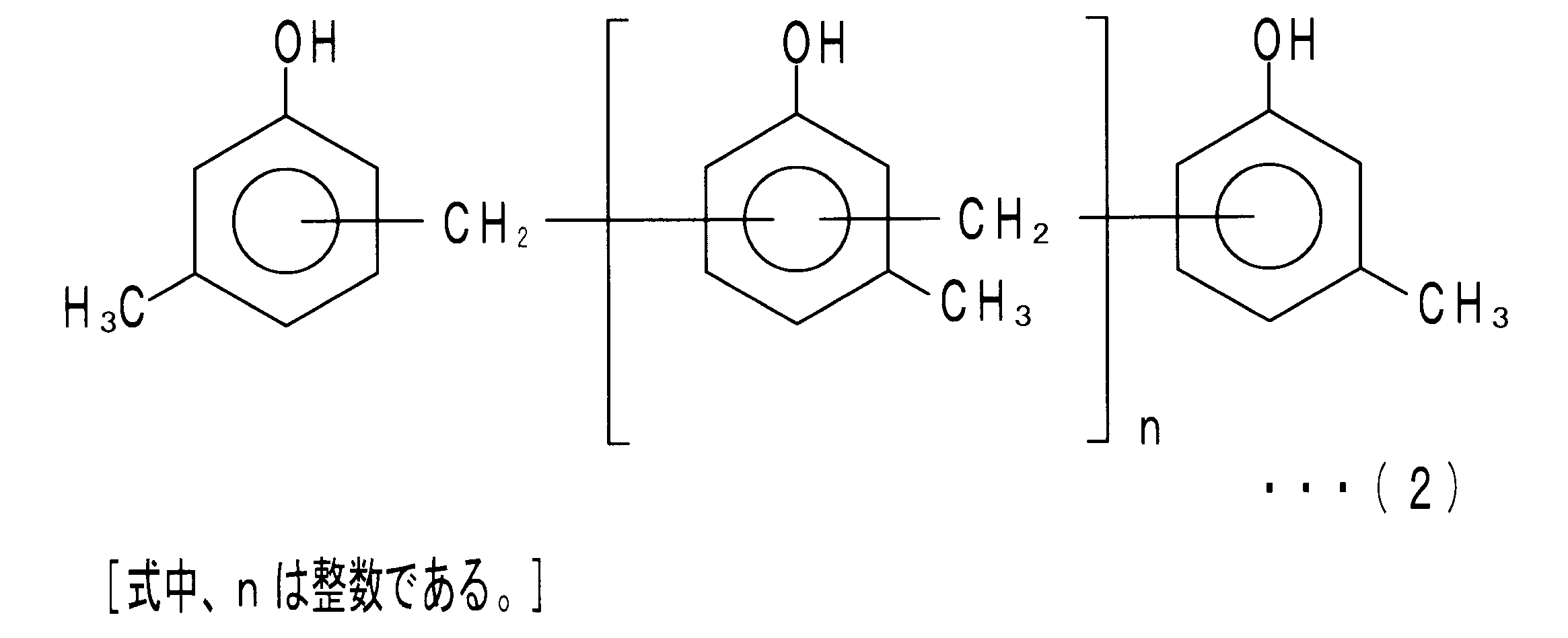
- resorcinol compounds include resorcin, modified resorcin / formaldehyde resin, resorcin / formaldehyde (RF) resin and the like. One of these may be used alone, or two or more may be mixed and used. Among them, the modified resorcinol / formaldehyde resin is preferable in terms of low volatility, low hygroscopicity, and excellent compatibility with rubber. Examples of the modified resorcin / formaldehyde resin include those represented by the following general formulas (1) to (3). In particular, those represented by the general formula (1) are preferable.
- the blending amount of the resorcinol compound is desirably 0.1 parts by mass or more with respect to 100 parts by mass of the rubber component. It is more preferable that it is 0.5 mass part or more. Moreover, since excessive compounding causes deterioration in the physical properties of the rubber, the compounding amount of the resorcinol compound is desirably 10 parts by mass or less. It is more preferable that it is 5 parts by mass or less.
- a melamine type compound the methylated thing of a formaldehyde * melamine polymer, hexamethylene tetramine, etc. are mentioned, for example. One of these may be used alone, or two or more may be mixed and used. These decompose under heating during crosslinking and supply formaldehyde to the system. Among them, methylated products of formaldehyde / melamine polymers are preferable in view of low volatility, low hygroscopicity, and excellent compatibility with rubber.
- the compounding ratio of the resorcinol compound to the melamine compound is preferably in the range of 1: 0.5 to 1: 2 by mass ratio.
- the range of 1: 0.77 to 1: 1.5 is more preferable.
- the aluminate coupling agent may be appropriately selected from aluminum organic compounds having a hydrolyzable alkoxy group and a portion having an affinity to the rubber component, in consideration of adhesion and the like.
- aluminum alkylacetoacetate / diisopropylate, aluminum ethylacetoacetate / diisopropylate, and aluminum trisethylacetoacetate are preferable.
- the compounding amount of the aluminate coupling agent is desirably 0.5 parts by mass or more with respect to 100 parts by mass of the rubber component. It is more preferable that it is 2 mass parts or more. In addition, excessive blending may lead to deterioration of the physical properties of the rubber, which may also reduce the processability. Therefore, the compounding amount of the aluminate coupling agent is preferably 10 parts by mass or less. It is more preferable that it is 6 parts by mass or less.
- the silane coupling agent may be appropriately selected from the group of compounds having an epoxy group, an amino group, a vinyl group or the like as a functional group, in consideration of adhesion and the like.
- One of these may be used alone, or two or more may be mixed and used. Above all, when one or more selected from a compound group having an epoxy group is used, the adhesion is improved, and the adhesion is not easily reduced even in the working environment of the fuel cell. Specifically, 3-glycidoxypropyltrimethoxysilane, 3-glycidoxypropyltriethoxysilane, 3-glycidoxypropylmethyldiethoxysilane, 2- (3,4-epoxycyclohexyl) ethyltrimethoxysilane Etc. are preferred.
- the blending amount of the silane coupling agent is desirably 0.5 parts by mass or more with respect to 100 parts by mass of the rubber component. It is more preferable that it is 2 mass parts or more. In addition, excessive blending may lead to deterioration of the physical properties of the rubber, which may also reduce the processability. For this reason, it is desirable for the compounding quantity of a silane coupling agent to be 10 mass parts or less. It is more preferable that it is 6 parts by mass or less.
- a softener having a pour point of ⁇ 40 ° C. or less is essential in the first adhesive seal member of the present invention, but is optional in the second adhesive seal member of the present invention. Also in the second adhesive seal member (rubber composition) of the present invention, it is desirable that a softener having a pour point of ⁇ 40 ° C. or less is included.
- Examples of the softener having a pour point of ⁇ 40 ° C. or less include poly ⁇ -olefin, dioctyl phthalate (DOP), dioctyl adipate (DOA), dioctyl sebacate (DOS), and dibutyl sebacate (DBS).
- DOP dioctyl phthalate
- DOA dioctyl adipate
- DOS dioctyl sebacate
- DBS dibutyl sebacate
- poly- ⁇ -olefins are preferable from the viewpoint of good compatibility with the rubber component and less bleeding.
- the poly ⁇ -olefin is obtained by polymerizing an ⁇ -olefin having 6 to 16 carbon atoms.
- the pour point of the more preferable softener is -50 ° C or less.
- the pour point of the softener is preferably ⁇ 80 ° C. or higher. The measurement of the pour point may be performed according to JIS K 2269 (1987).
- the blending amount of the softener is desirably 5 parts by mass or more with respect to 100 parts by mass of the rubber component.
- the first adhesive seal member of the present invention can maintain good sealability without losing its rubber elasticity even at very low temperatures.
- the sealability under cryogenic temperature can be improved. More preferably, it is 10 parts by mass or more, and further preferably 20 parts by mass or more.
- the compounding quantity of a softener is desirable to be 50 mass parts or less with respect to 100 mass parts of rubber components. More preferably, it is 40 parts by mass or less, and more preferably 30 parts by mass or less.
- the rubber composition constituting the adhesive seal member of the present invention may contain, in addition to the above (A) to (E), various additives which are usually used as additives for rubber.
- various additives which are usually used as additives for rubber.
- carbon black as a reinforcing agent.
- the grade of carbon black is not particularly limited, and may be appropriately selected from SAF, ISAF, HAF, MAF, FEF, GPF, SRF, FT, MT, and the like.
- the compounding amount of carbon black is increased, the adhesive seal member becomes hard. Thereby, there is a possibility that tensile strength and elongation may fall. For this reason, it is desirable to make the compounding quantity of carbon black into 10 mass parts or more and 70 mass parts or less with respect to 100 mass parts of a rubber component.
- additives include anti-aging agents, tackifiers, processing aids and the like.
- anti-aging agents phenols, imidazoles, waxes and the like can be mentioned.
- the antioxidant may be blended in an amount of about 0.5 to 10 parts by mass with respect to 100 parts by mass of the rubber component. Further, together with the above-mentioned softener (E), a softener having a pour point higher than ⁇ 40 ° C. may be blended.
- softeners that can be used in combination include process oils, lubricating oils, petroleum softeners such as paraffin, liquid paraffin, petrolatum and the like, castor oil, linseed oil, rapeseed oil, fatty oils such as rapeseed oil, coconut oil, tall oil And waxes such as beeswax, carnauba wax and lanolin, linoleic acid, palmitic acid, stearic acid, lauric acid and the like.
- petroleum softeners such as paraffin, liquid paraffin, petrolatum and the like, castor oil, linseed oil, rapeseed oil, fatty oils such as rapeseed oil, coconut oil, tall oil And waxes such as beeswax, carnauba wax and lanolin, linoleic acid, palmitic acid, stearic acid, lauric acid and the like.
- the first adhesive seal member of the present invention is produced by crosslinking the rubber composition containing the above (A) to (E) and, if necessary, various additives.
- the second adhesive seal member of the present invention is produced by crosslinking the rubber composition containing the above-mentioned (A) to (D) and, if necessary, the softening agent of (E) and various additives.
- the rubber composition may be prepared, for example, as follows. First, materials other than (B) organic peroxide, (C) cross-linking aid, and (D) adhesive component are premixed and kneaded at 80 to 140 ° C. for several minutes.
- the resulting kneaded product is cooled, and (B) organic peroxide, (C) crosslinking aid, and (D) adhesive component are added. Then, using rolls such as an open roll, kneading is carried out at a roll temperature of 40 to 70 ° C. for 5 to 30 minutes.
- the adhesive component (D) may be blended at the preliminary mixing stage.
- the prepared rubber composition is crosslinked at a predetermined temperature.
- the rubber composition becomes the adhesive seal member of the present invention.
- the crosslinking temperature is desirably 150 ° C. or less.
- the adhesive seal member of the present invention can be used, for example, also in the vicinity of the electrolyte membrane of a polymer electrolyte fuel cell.
- the adhesive seal member can be attached to the member to be easily crosslinked and adhered. In this case, since the complicated alignment of the constituent members of the fuel cell becomes unnecessary, continuous processing becomes easy. In addition, if the adhesive seal member is laminated on the member in advance, the bonding operation is further facilitated. Thus, by making the adhesive seal member of the present invention in the form of a film, for example, the productivity of the fuel cell can be further improved. Further, it is also possible to integrally mold by putting a component such as MEA of a fuel cell, a separator and the like and the adhesive sealing member of the present invention in a mold and heating.
- the crosslink density should be high.
- the value of 100% modulus can be used as an index.
- the 100% modulus of the adhesive seal member of the present invention is desirably 2 MPa or more and 4 MPa or less.
- the 100% modulus is a value obtained by dividing the tensile force when the dumbbell-shaped test piece is elongated 100% by the initial cross-sectional area of the dumbbell-shaped test piece.
- the 100% modulus may be measured according to JIS K6251 (2010).
- the adhesive seal member of the present invention is excellent in sealability even at extremely low temperatures. This is also apparent from the fact that the Gehman torsion test temperature T2 of the adhesive seal member of the present invention is ⁇ 40 ° C. or lower, as will be shown later in the Examples.
- the Gehman torsion test may be performed according to JIS K6261 (2006).
- T2 is a temperature at which the specific modulus is doubled with respect to the modulus at room temperature (23 ° C. ⁇ 2 ° C.).
- T 2 is ⁇ 40 ° C. or less, rubber elasticity is maintained even at a very low temperature, and desired sealability can be secured.
- the adhesive seal member of the present invention seals components of a fuel cell.
- the fuel cell to be applied may be one that operates at a temperature at which the rubber component of the adhesive seal member of the present invention can be used.
- a polymer electrolyte fuel cell PEFC
- DMFC direct methanol fuel cell
- the part to be sealed varies depending on the type and structure of the fuel cell. That is, the adhesive seal member of the present invention is required to be airtight and liquid tight, and can be used for any portion where the seal member has been conventionally disposed. In addition, the adhesive seal member of the present invention may be used in all parts where sealing is required in a fuel cell, or in part of parts where sealing is necessary.
- part between the separators and separators which pinched
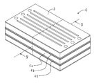
- FIG. 1 shows a perspective view of a polymer electrolyte fuel cell using the adhesive seal member of the present invention.
- the polymer electrolyte fuel cell 1 is configured by stacking a large number of cells C.
- FIG. 2 shows a perspective view of the stacked cells C (only three pieces).
- FIG. 3 shows an exploded perspective view of a single cell C.
- FIG. 4 shows a IV-IV cross-sectional view of FIG.
- the cell C includes the MEA 2, the separator 3, and the adhesive seal member 4 a.
- the MEA 2 includes an electrolyte membrane 20 and a pair of electrodes 21a and 21b.
- the electrolyte membrane 20 has a rectangular thin plate shape.
- the pair of electrodes 21a and 21b have a rectangular thin plate shape.
- the pair of electrodes 21 a and 21 b are disposed on both sides in the stacking direction (vertical direction) with the electrolyte membrane 20 interposed therebetween.
- the separator 3 is made of metal and has a rectangular thin plate shape.
- the separator 3 is provided with a total of six grooves extending in the longitudinal direction.
- the cross section of the separator 3 has an uneven shape due to the groove (see FIG. 4).
- the separators 3 are disposed to face each other on both sides in the stacking direction of the MEA 2.
- a gas flow path 30 for supplying a gas to the electrodes 21a and 21b is partitioned between the MEA 2 and the separator 3 by using the uneven shape.
- a refrigerant flow path 31 for flowing the refrigerant is partitioned between the separators 3 facing each other in the cell C adjacent in the stacking direction, using the uneven shape.
- the adhesive seal member 4a has a rectangular frame shape with a large thickness in the stacking direction.
- the adhesive seal member 4 a is bonded to the periphery of the MEA 2 and the separator 3 to be stacked. Moreover, the adhesive seal member 4 a seals the periphery of the MEA 2 between the facing separators 3.
- An adhesive seal member 4 b is interposed between the facing separators 3 of the cells C adjacent in the stacking direction.
- the adhesive seal member 4 b has a rectangular frame shape with a thin thickness in the stacking direction.
- the lower surface of the adhesive seal member 4b is bonded to the upper surface of the separator 3 disposed below.
- a frame-shaped lip portion 40b is formed on the upper surface peripheral portion of the adhesive seal member 4b (in FIG. 3, the adhesive seal member 4b shown above the cell C is shown by hatching).
- the lip portion 40 b is in contact with the lower surface of the separator 3 disposed above.
- the lip portion 40 b is pressed and deformed by the fastening force in the stacking direction when the solid electrolyte fuel cell 1 is assembled by stacking the cells C. Thereby, the seal line is formed, and the leakage of the refrigerant is suppressed.
- Adhesive seal members 4a and 4b are included in the adhesive seal member of the present invention.
- the polymer electrolyte fuel cell 1 fuel gas and oxidant gas are respectively supplied through the gas flow path 30.
- the refrigerant flows through the refrigerant flow path 31 in order to reduce the heat generation at the time of power generation.
- the periphery of the MEA 2 is sealed by the adhesive seal member 4 a.
- the adhesive seal member 4a can be bonded at a low temperature of about 150 ° C. and in a short time. Therefore, there is little possibility that the electrolyte membrane 20 may be deteriorated at the time of adhesion processing.
- the adhesive seal member 4 b also seals between the separators 3 facing each other in the cells C adjacent in the stacking direction. For this reason, the refrigerant is unlikely to leak out of the refrigerant channel 31. In addition, the sealability of the adhesive seal members 4a and 4b is unlikely to decrease even at a very low temperature of about -20 to -30 ° C. Furthermore, the adhesiveness of the adhesive seal members 4 a and 4 b is unlikely to be degraded even in the operating environment of the polymer electrolyte fuel cell 1. Therefore, the polymer electrolyte fuel cell 1 is excellent in durability. That is, the polymer electrolyte fuel cell 1 can be stably operated over a long period of time.
- EPDM (4): "Keltan (registered trademark) 4903” manufactured by DSM (ethylene content 48% by mass).
- C Crosslinking auxiliary maleimide compound: "Barnock (registered trademark) PM” manufactured by Ouchi Emerging Chemical Industry Co., Ltd.
- Adhesive component resorcinol compound "Takkirol (registered trademark) 620” manufactured by Taoka Chemical Industry Co., Ltd.
- the rubber compositions of Examples 1 to 13 and Comparative Example 1 were crosslinked by holding at 150 ° C. for 10 minutes to produce a seal member.
- the seal members of Examples 1-11 are included in both the first and second adhesive seal members of the present invention.
- the seal member of Example 12 is included in the first adhesive seal member of the present invention.
- the seal member of Example 13 is included in the second adhesive seal member of the present invention.
- the 100% modulus of each of the seal members of the example was 2 MPa or more, and was larger than the 100% modulus of the seal member of Comparative Example 1.
- the blending amount of the crosslinking aid is larger than that of the seal members of the comparative example. For this reason, in the seal member of the example, the crosslink density increased and the 100% modulus increased.
- a 90 ° peel test in accordance with JIS K 6256-2 (2006) was conducted to evaluate the adhesiveness of the seal members of the examples and comparative examples.
- a flat rubber composition having a width of 25 mm, a length of 60 mm and a thickness of 5 mm was disposed on the surface of a stainless steel plate having a width of 25 mm, a length of 60 mm and a thickness of 2 mm.
- a test piece was produced by holding at 150 ° C. for 10 minutes for crosslinking and adhesion.
- the produced test piece was attached to a predetermined
- the peel strength of each test piece in the 90 ° peel test is summarized in Table 1 above.
- Table 1 when the peel strength of the seal member of Comparative Example 1 is used as a reference (100), the index of the peel strength of each seal member is shown.
- the peel strengths of the seal members of the examples were all the same as the peel strength of the seal member of Comparative Example 1. Thus, the adhesiveness of the seal member of the example is good.
- T2 of the seal member of Comparative Example 1 was -31.degree. C.
- T2 of the seal members of the examples was -40.degree. C. or less. From this result, it is understood that the seal member of the example is hard to be hard even at a very low temperature of ⁇ 20 to ⁇ 30 ° C., and the rubber elasticity can be maintained.
- Example 12 using the same EPDM is compared with Comparative Example 1, the seal member of Example 12 containing poly ⁇ -olefin (2) having a pour point of -48 ° C has a pour point of -15 ° C. T2 was lower than that of the seal member of Comparative Example 1 containing paraffinic process oil. From this result, it is possible to confirm the effect of suppressing the decrease in rubber elasticity by the softener having a pour point of -40 ° C or less.
- Example 13 containing only paraffinic process oil having a pour point of -15 ° C. is compared with Comparative Example 1 as a softener, EPDM (4) having an ethylene content of 48% by mass is used.
- the seal member had a lower T2 than the seal member of Comparative Example 1 using EPDM (1) having an ethylene content of 54% by mass. From this result, it can be confirmed that when the ethylene content of EPDM is 53% by mass or less, crystallization at a very low temperature is suppressed, and a decrease in rubber elasticity can be suppressed.
- the seal member of Example 2 contains, as a softener, both of poly ⁇ -olefin (1) having a pour point of ⁇ 60 ° C. and paraffinic process oil having a pour point of ⁇ 15 ° C. For this reason, in the seal member of Example 2, T2 was slightly increased as compared with the seal member of Example 1 containing the same amount of poly ⁇ -olefin (1) having a pour point of -60 ° C.
- compression set strain test The compression set test based on JIS K6262 (2006) was performed on the seal members of the example and the comparative example.
- the compression set test was performed in two types, a low temperature test at ⁇ 30 ° C. and a high temperature test at 100 ° C.
- a low temperature test After compression at -30 ° C. for 24 hours, it was released, and the thickness after 30 minutes under the same temperature was measured to calculate the compression set.
- the high temperature test after compression at 100 ° C. for 24 hours, it was released, and the thickness after 30 minutes at room temperature was measured to calculate the compression set.
- the compression rate was 25% in all the tests.
- Table 1 The measurement results are summarized in Table 1 above. In Table 1, the compression set at ⁇ 30 ° C. and 100 ° C.
- the compression set was smaller than that of the seal member of Comparative Example 1 including the paraffinic process oil having a pour point of -15.degree. From this result, it is possible to confirm the effect of suppressing the decrease in rubber elasticity by the softener having a pour point of -40 ° C or less. Further, when Example 13 containing only paraffinic process oil having a pour point of -15 ° C. is compared with Comparative Example 1 as a softener, EPDM (4) having an ethylene content of 48% by mass is used. The compression set of the seal member was smaller than that of the seal member of Comparative Example 1 in which EPDM (1) having an ethylene content of 54% by mass was used. From this result, it can be confirmed that when the ethylene content of EPDM is 53% by mass or less, crystallization at a very low temperature is suppressed, and a decrease in rubber elasticity can be suppressed.
- the seal member of the example is resistant to settling at a high temperature of 100 ° C. and a cryogenic temperature of ⁇ 30 ° C. Therefore, according to the adhesive seal member of the present invention, it is possible to realize the improvement of the sealing property under the cryogenic temperature without sacrificing the sealing property under the high temperature.
- the adhesive seal member of the present invention adhesion to the member is possible at a low temperature and in a short time without using any other adhesive.
- the adhesive seal member of the present invention does not lose its rubber elasticity even at a very low temperature of about -20 to -30 ° C. For this reason, a good sealing performance is exhibited even in cold regions.
- both adhesive and stress seals are possible over the wide temperature range in which the fuel cell is used.
Landscapes
- Chemical & Material Sciences (AREA)
- Chemical Kinetics & Catalysis (AREA)
- Sustainable Development (AREA)
- Life Sciences & Earth Sciences (AREA)
- Sustainable Energy (AREA)
- Manufacturing & Machinery (AREA)
- Engineering & Computer Science (AREA)
- Electrochemistry (AREA)
- General Chemical & Material Sciences (AREA)
- Health & Medical Sciences (AREA)
- Medicinal Chemistry (AREA)
- Polymers & Plastics (AREA)
- Organic Chemistry (AREA)
- Fuel Cell (AREA)
Abstract
本発明の燃料電池用接着性シール部材は、以下の(A)~(E)を含むゴム組成物の架橋物からなる。(A)エチレン-プロピレンゴムおよびエチレン-プロピレン-ジエンゴムから選ばれる一種以上のゴム成分、(B)1時間半減期温度が130℃以下の有機過酸化物、(C)架橋助剤、(D)レゾルシノール系化合物およびメラミン系化合物と、アルミネート系カップリング剤と、シランカップリング剤と、から選ばれる一種以上の接着成分、(E)流動点が-40℃以下の軟化剤。ゴム成分(A)のエチレン-プロピレンゴムおよびエチレン-プロピレン-ジエンゴムのエチレン含有量が53質量%以下の場合、ゴム組成物は、流動点が-40℃以下の軟化剤(E)を含まなくてもよい。
Description
本発明は、燃料電池の構成部材をシールする接着性シール部材に関し、詳しくは、極低温下でもシール性が良好な接着性シール部材に関する。
ガスの電気化学反応により電気を発生させる燃料電池は、発電効率が高く、排出されるガスがクリーンで環境に対する影響が極めて少ない。なかでも固体高分子型燃料電池は、比較的低温で作動させることができ、大きな出力密度を有する。このため、発電用、自動車用電源等、種々の用途が期待される。
固体高分子型燃料電池においては、膜電極接合体(MEA)等をセパレータで挟持したセルが発電単位となる。MEAは、電解質となる高分子膜(電解質膜)と、電解質膜の厚さ方向両面に配置された一対の電極触媒層(燃料極(アノード)触媒層、酸素極(カソード)触媒層)と、からなる。一対の電極触媒層の表面には、さらにガスを拡散させるための多孔質層が配置される。燃料極側には水素等の燃料ガスが、酸素極側には酸素や空気等の酸化剤ガスがそれぞれ供給される。供給されたガスと電解質と電極触媒層との三相界面における電気化学反応により、発電が行われる。固体高分子型燃料電池は、上記セルを多数積層したセル積層体を、セル積層方向の両端に配置したエンドプレート等により締め付けて構成される。
セパレータには、各々の電極に供給されるガスの流路や、発電の際の発熱を緩和するための冷媒の流路が形成される。例えば、各々の電極に供給されるガスが混合すると、発電効率が低下する等の問題が生じる。また、電解質膜は、水を含んだ状態でプロトン導電性を有する。このため、作動時には、電解質膜を湿潤状態に保つ必要がある。したがって、ガスの混合、ガスおよび冷媒の漏れを防止すると共に、セル内を湿潤状態に保持するためには、MEAおよび多孔質層の周囲や、隣り合うセパレータ間のシール性を確保することが重要となる。これらの構成部材をシールするシール部材としては、例えば、特許文献1、2において、エチレン-プロピレンゴム(EPM)、エチレン-プロピレン-ジエンゴム(EPDM)等を用いたゴム材料が提案されている。
固体高分子型燃料電池の電解質膜には、全フッ素系スルホン酸膜等の高分子膜が用いられる。このため、ゴム組成物を電解質膜の近くに配置して架橋、接着する場合には、架橋時の加熱により、電解質膜が劣化しないよう配慮する必要がある。つまり、シール部材の架橋、接着工程を、より低温で、かつ短時間で行うことが望ましい。
この点、上記特許文献1、2に記載のシール部材を構成するゴム組成物は、130℃以下の低温で、比較的短時間で架橋することができる。したがって、当該シール部材は、電解質膜の近傍にも適用可能である。また、当該シール部材は、接着成分を含む。このため、他の接着剤を使用しなくても、部材と接着することができる。しかしながら、-20~-30℃程度の極低温下では、EPMやEPDMのゴム弾性が失われるおそれがある。このため、寒冷地等において燃料電池を使用する場合、所望のシール性を確保することが難しい。
本発明はこのような実状に鑑みてなされたものであり、低温かつ短時間で架橋することができると共に、極低温下においてもシール性が良好な燃料電池用接着性シール部材を提供することを課題とする。
上記課題を解決するため、本発明の第一の燃料電池用接着性シール部材(以下、適宜「本発明の第一の接着性シール部材」と称す)は、以下の(A)~(E)を含むゴム組成物の架橋物からなり、燃料電池の構成部材をシールすることを特徴とする。
(A)エチレン-プロピレンゴムおよびエチレン-プロピレン-ジエンゴムから選ばれる一種以上のゴム成分。
(B)1時間半減期温度が130℃以下の有機過酸化物。
(C)架橋助剤。
(D)レゾルシノール系化合物およびメラミン系化合物と、アルミネート系カップリング剤と、シランカップリング剤と、から選ばれる一種以上の接着成分。
(E)流動点が-40℃以下の軟化剤。
(A)エチレン-プロピレンゴムおよびエチレン-プロピレン-ジエンゴムから選ばれる一種以上のゴム成分。
(B)1時間半減期温度が130℃以下の有機過酸化物。
(C)架橋助剤。
(D)レゾルシノール系化合物およびメラミン系化合物と、アルミネート系カップリング剤と、シランカップリング剤と、から選ばれる一種以上の接着成分。
(E)流動点が-40℃以下の軟化剤。
EPMやEPDMに軟化剤を配合すると、ガラス転移点(Tg)が低下する。しかしながら、軟化剤の流動点が高い場合、軟化剤を配合しても、極低温下におけるゴム弾性の低下を改善することはできない。例えば、上記特許文献3、4には、ポリαオレフィン等の軟化剤を含むゴム組成物が開示されている。同文献によると、軟化剤は、ゴム成形体の潤滑性や柔軟性を向上させるために、配合されているにすぎない。よって、軟化剤の流動点は、何ら考慮されていない。この点、本発明の第一の接着性シール部材は、流動点が-40℃以下の軟化剤を含む(上記(E))。流動点が-40℃以下の軟化剤は、-20~-30℃程度の極低温下においても、粘度が小さく流れやすい。このため、EPMやEPDMに当該軟化剤を配合すると、極低温下におけるゴム弾性の低下を抑制することができる。したがって、本発明の第一の接着性シール部材は、極低温下においてもシール性に優れる。
また、本発明の第二の燃料電池用接着性シール部材(以下、適宜「本発明の第二の接着性シール部材」と称す)は、以下の(A)~(D)を含むゴム組成物の架橋物からなり、燃料電池の構成部材をシールすることを特徴とする。
(A)エチレン含有量が53質量%以下のエチレン-プロピレンゴムおよびエチレン-プロピレン-ジエンゴムから選ばれる一種以上のゴム成分。
(B)1時間半減期温度が130℃以下の有機過酸化物。
(C)架橋助剤。
(D)レゾルシノール系化合物およびメラミン系化合物と、アルミネート系カップリング剤と、シランカップリング剤と、から選ばれる一種以上の接着成分。
(A)エチレン含有量が53質量%以下のエチレン-プロピレンゴムおよびエチレン-プロピレン-ジエンゴムから選ばれる一種以上のゴム成分。
(B)1時間半減期温度が130℃以下の有機過酸化物。
(C)架橋助剤。
(D)レゾルシノール系化合物およびメラミン系化合物と、アルミネート系カップリング剤と、シランカップリング剤と、から選ばれる一種以上の接着成分。
上記特許文献1、2に記載のシール部材においては、EPM、EPDMのエチレン含有量は、考慮されていない。これに対して、本発明の第二の接着性シール部材においては、ゴム成分として用いるEPM、EPDMのエチレン含有量を限定した。EPM、EPDMは、エチレン含有量が少ないほど、-20~-30℃程度の極低温下で結晶化しにくい。つまり、エチレン含有量が少ないEPM、EPDMは、極低温下においてもゴム弾性が低下しにくい。本発明の第二の接着性シール部材は、ゴム成分として、エチレン含有量が53質量%以下と少ないEPMおよびEPDMの一種以上を用いる。このため、流動点が-40℃以下の軟化剤を含む場合は勿論、当該軟化剤を含まなくても、極低温下においてゴム弾性を維持することができる。したがって、本発明の第二の接着性シール部材は、極低温下においてもシール性に優れる。
本発明の第一および第二の接着性シール部材(以下、まとめて「本発明の接着性シール部材」と称す)は、いずれも接着成分を含む(上記(D))。よって、本発明の接着性シール部材は、他の接着剤を使用することなく、部材と接着することができる。例えば、接着成分としてレゾルシノール系化合物およびメラミン系化合物を含む場合には、メラミン系化合物がメチレン供与体となり、レゾルシノール系化合物がメチレン授与体となる。架橋時に、メチレン基の供与により、レゾルシノール系化合物とゴム成分、およびレゾルシノール系化合物と接着対象の部材の間に、各々、化学結合が形成される。これにより、ゴム成分(接着性シール部材)と部材とが接着される。また、接着成分としてアルミネート系カップリング剤を含む場合には、アルミネート系カップリング剤を介して、接着性シール部材と部材とが接着される。同様に、接着成分としてシランカップリング剤を含む場合には、シランカップリング剤を介して、接着性シール部材と部材とが接着される。
これらの接着成分の接着力は大きい。加えて、燃料電池の作動環境においても、接着力は低下しにくい。したがって、本発明の接着性シール部材によると、燃料電池を長期間作動させた場合でも、良好なシール性が確保される。すなわち、燃料電池の作動信頼性を向上させることができる。
本発明の接着性シール部材において、「燃料電池の構成部材をシールする」とは、構成部材の周囲や、構成部材間をシールすることを意味する。本発明の接着性シール部材は、燃料電池の作動温度から-30℃程度までの広い温度範囲で、ゴム弾性を有する。このため、本発明の接着性シール部材によると、接着によるシールだけでなく、応力によるシールが可能となる。例えば、本発明の接着性シール部材を、対向する部材間に配置する場合、本発明の接着性シール部材を一方の部材にのみ接着して、他方の部材との間は応力によりシールする態様を採用することができる。勿論、本発明の接着性シール部材を両方の部材に各々接着して、部材間を接着シールする態様を採用してもよい。極低温下でゴム弾性が失われると、接着シールよりも、応力シールにおいてシール性が低下しやすい。この点、本発明の接着性シール部材によると、極低温下においてもゴム弾性が維持されるため、応力シールであってもシール性が低下しにくい。
また、本発明の接着性シール部材によると、架橋剤として、1時間半減期温度が130℃以下の有機過酸化物を用いる(上記(B))。ここで「半減期」とは、有機過酸化物の濃度が初期値の半分になるまでの時間である。よって、「半減期温度」は、有機過酸化物の分解温度を示す指標となる。上記「1時間半減期温度」は、半減期が1時間となる温度である。つまり、1時間半減期温度が低いほど、低温で分解しやすい。1時間半減期温度が130℃以下の有機過酸化物を用いることにより、架橋をより低温(具体的には150℃以下)で、かつ短時間で行うことができる。したがって、例えば、固体高分子型燃料電池の電解質膜の近傍においても、本発明の接着性シール部材を使用することができる。
1:固体高分子型燃料電池、2:MEA、20:電解質膜、21a、21b:電極、3:セパレータ、30:ガス流路、31:冷媒流路、4a、4b:接着性シール部材、40b:リップ部、C:セル。
以下に、本発明の燃料電池用接着性シール部材の実施形態を説明する。なお、本発明の燃料電池用接着性シール部材は、下記の実施形態に限定されるものではなく、本発明の要旨を逸脱しない範囲において、当業者が行い得る変更、改良等を施した種々の形態にて実施することができる。
<燃料電池用接着性シール部材>
上述したように、本発明の第一の接着性シール部材は、上記(A)~(E)を含むゴム組成物の架橋物からなる。本発明の第二の接着性シール部材は、上記(A)~(D)を含むゴム組成物の架橋物からなる。まず、(A)のゴム成分について説明する。
上述したように、本発明の第一の接着性シール部材は、上記(A)~(E)を含むゴム組成物の架橋物からなる。本発明の第二の接着性シール部材は、上記(A)~(D)を含むゴム組成物の架橋物からなる。まず、(A)のゴム成分について説明する。
本発明の第一の接着性シール部材に用いるゴム成分は、エチレン-プロピレンゴム(EPM)およびエチレン-プロピレン-ジエンゴム(EPDM)から選ばれる一種以上である。ゴム成分としては、EPM、EPDMの一方を用いてもよく、両方を混合して用いてもよい。また、後述するエチレン含有量等が異なる二つ以上の同種のゴムを、混合して用いてもよい。燃料電池の作動環境における耐酸性および耐水性を考慮すると、ゴム成分は、EPDMを含むことが望ましい。
EPM、EPDMは、エチレン含有量が少ないほど、極低温下で結晶化しにくい。つまり、エチレン含有量が少ないEPM、EPDMは、極低温下においてもゴム弾性が低下しにくい。したがって、極低温下におけるゴム弾性の低下を抑制し、シール性を向上させるという観点から、ゴム成分としては、エチレン含有量が53質量%以下のEPM、EPDMを用いることが望ましい。エチレン含有量が50質量%以下のEPM、EPDMが、より好適である。一方、エチレン含有量が少なすぎると、ゴムの物性が低下するおそれがある。したがって、接着性シール部材に必要な伸びや引張り強さを確保するという観点から、ゴム成分としては、エチレン含有量が40質量%以上のEPM、EPDMを用いることが望ましい。
本発明の第二の接着性シール部材に用いるゴム成分は、エチレン含有量が53質量%以下のエチレン-プロピレンゴム(EPM)およびエチレン-プロピレン-ジエンゴム(EPDM)から選ばれる一種以上である。エチレン含有量が53質量%以下であれば、EPM、EPDMの一方を用いてもよく、両方を混合して用いてもよい。また、エチレン含有量等が異なる二つ以上の同種のゴムを、混合して用いてもよい。上述した本発明の第一の接着性シール部材と同様、燃料電池の作動環境における耐酸性および耐水性を考慮すると、ゴム成分は、EPDMを含むことが望ましい。また、極低温下におけるゴム弾性の低下を抑制し、シール性をより向上させるという観点から、エチレン含有量が50質量%以下のEPM、EPDMが、より好適である。一方、エチレン含有量が少なすぎると、ゴムの物性が低下するおそれがある。したがって、接着性シール部材に必要な伸びや引張り強さを確保するという観点から、ゴム成分としては、エチレン含有量が40質量%以上のEPM、EPDMを用いることが望ましい。
次に、(B)の有機過酸化物について説明する。1時間半減期温度が130℃以下の有機過酸化物としては、パーオキシケタール、パーオキシエステル、ジアシルパーオキサイド、パーオキシジカーボネート等が挙げられる。なかでも、130℃程度の温度で架橋しやすく、架橋剤を加えて混練したゴム組成物の取扱性にも優れるという理由から、1時間半減期温度が100℃以上のパーオキシケタールおよびパーオキシエステルの少なくとも一種を採用することが望ましい。特に、1時間半減期温度が110℃以上のものが好適である。また、パーオキシエステルを用いると、より短時間で架橋を行うことができる。
パーオキシケタールとしては、例えば、n-ブチル4,4-ジ(t-ブチルパーオキシ)バレレート、2,2-ジ(t-ブチルパーオキシ)ブタン、2,2-ジ(4,4-ジ(t-ブチルパーオキシ)シクロヘキシル)プロパン、1,1-ジ(t-ブチルパーオキシ)シクロヘキサン、1,1-ジ(t-ヘキシルパーオキシ)シクロヘキサン、1,1-ジ(t-ヘキシルパーオキシ)-3,3,5-トリメチルシクロヘキサン、1,1-ジ(t-ブチルパーオキシ)-2-メチルシクロヘキサン等が挙げられる。
また、パーオキシエステルとしては、例えば、t-ブチルパーオキシベンゾエート、t-ブチルパーオキシアセテート、t-ヘキシルパーオキシベンゾエート、2,5-ジメチル-2,5-ジ(ベンゾイルパーオキシ)ヘキサン、t-ブチルパーオキシ2-エチルヘキシルモノカーボネート、t-ブチルパーオキシラウレート、t-ブチルパーオキシイソプロピルモノカーボネート、t-ブチルパーオキシ-3,5,5-トリメチルヘキサノエート、t-ブチルパーオキシマレイン酸、t-ヘキシルパーオキシイソプロピルモノカーボネート等が挙げられる。
これらのうち、ゴム成分との反応が比較的速いという理由から、1,1-ジ(t-ブチルパーオキシ)シクロヘキサン、t-ブチルパーオキシアセテート、t-ブチルパーオキシイソプロピルモノカーボネートが好適である。なかでも、t-ブチルパーオキシイソプロピルモノカーボネートを用いると、より短時間で架橋を行うことができる。
次に、(C)の架橋助剤について説明する。架橋助剤は、上記有機過酸化物(B)の種類に応じて適宜選択すればよい。架橋助剤としては、例えば、マレイミド化合物、トリアリルシアヌレート(TAC)、トリアリルイソシアヌレート(TAIC)、トリメチロールプロパントリメタクリレート(TMPT)等が挙げられる。なかでも、架橋密度や引張り強さの向上効果が大きいという理由から、マレイミド化合物を用いることが望ましい。
ゴム成分が架橋されると、架橋点において分子が拘束される。このため、架橋点が多いほど、ゴム成分は結晶化しにくい。すなわち、架橋密度を大きくすることにより、極低温下におけるゴム成分の結晶化を、抑制することができる。架橋密度を大きくするためには、例えば、有機過酸化物(B)や架橋助剤(C)の配合量を増加すればよい。このような観点から、有機過酸化物の配合量は、ゴム成分の100質量部に対して1質量部以上であることが望ましい。一方、有機過酸化物の配合量が多すぎると、架橋反応時に架橋密度が急激に上昇して、接着力の低下を招く。よって、有機過酸化物の配合量は、ゴム成分の100質量部に対して10質量部以下であることが望ましい。同様に、架橋助剤の配合量は、ゴム成分の100質量部に対して0.1質量部以上とすることが望ましい。一方、架橋助剤の配合量が多すぎると、架橋密度が大きくなりすぎて、接着力の低下を招く。このため、架橋助剤の配合量は、3質量部以下とすることが望ましい。
次に、(D)の接着成分について説明する。接着成分(D)は、レゾルシノール系化合物およびメラミン系化合物と、アルミネート系カップリング剤と、シランカップリング剤と、から選ばれる一種以上である。すなわち、レゾルシノール系化合物およびメラミン系化合物、アルミネート系カップリング剤、シランカップリング剤、を各々単独で用いてもよい。また、レゾルシノール系化合物およびメラミン系化合物とアルミネート系カップリング剤、レゾルシノール系化合物およびメラミン系化合物とシランカップリング剤、アルミネート系カップリング剤とシランカップリング剤、を各々組み合わせて使用してもよい。さらには、レゾルシノール系化合物およびメラミン系化合物と、アルミネート系カップリング剤と、シランカップリング剤と、を全て使用してもよい。
レゾルシノール系化合物としては、例えば、レゾルシン、変性レゾルシン・ホルムアルデヒド樹脂、レゾルシン・ホルムアルデヒド(RF)樹脂等が挙げられる。これらの一種を単独で用いてもよく、二種以上を混合して用いてもよい。なかでも、低揮発性、低吸湿性、ゴムとの相溶性が優れるという点で、変性レゾルシン・ホルムアルデヒド樹脂が好適である。変性レゾルシン・ホルムアルデヒド樹脂としては、例えば、次の一般式(1)~(3)で表されるものが挙げられる。特に、一般式(1)で表されるものが好適である。


所望の接着力を得るため、レゾルシノール系化合物の配合量は、ゴム成分の100質量部に対して、0.1質量部以上であることが望ましい。0.5質量部以上であるとより好適である。また、過剰な配合はゴムの物性低下を招くため、レゾルシノール系化合物の配合量は10質量部以下であることが望ましい。5質量部以下であるとより好適である。
メラミン系化合物としては、例えば、ホルムアルデヒド・メラミン重合物のメチル化物、ヘキサメチレンテトラミン等が挙げられる。これらの一種を単独で用いてもよく、二種以上を混合して用いてもよい。これらは、架橋の際の加熱下で分解し、ホルムアルデヒドを系に供給する。なかでも、低揮発性、低吸湿性、ゴムとの相溶性が優れるという点で、ホルムアルデヒド・メラミン重合物のメチル化物が好適である。ホルムアルデヒド・メラミン重合物のメチル化物としては、例えば、以下の一般式(4)で表されるものが好適である。特に、一般式(4)中、n=1の化合物が43~44質量%、n=2の化合物が27~30質量%、n=3の化合物が26~30質量%の混合物が好適である。

上記レゾルシノール系化合物とメラミン系化合物との配合比は、質量比で、1:0.5~1:2の範囲が望ましい。1:0.77~1:1.5の範囲がより好適である。レゾルシノール系化合物に対するメラミン系化合物の配合比が0.5未満の場合、ゴムの引張り強さ、伸び等が若干低下する傾向がみられる。反対に、メラミン系化合物の配合比が2を超えると、接着力が飽和する。このため、それ以上の配合は、コストアップにつながる。
アルミネート系カップリング剤は、加水分解可能なアルコキシ基と、ゴム成分と親和性がある部分と、を有するアルミニウム有機化合物の中から、接着性等を考慮して適宜選択すればよい。例えば、アルミニウムアルキルアセトアセテート・ジイソプロピレート、アルミニウムエチルアセトアセテート・ジイソプロピレート、アルミニウムトリスエチルアセトアセテート、アルミニウムイソプロピレート、アルミニウムジイソプロピレートモノセカンダリーブチレート、アルミニウムセカンダリーブチレート、アルミニウムエチレート、アルミニウムビスエチルアセトアセテート・モノアセチルアセトネート、アルミニウムトリスアセチルアセトネート、アルミニウムモノイソプロポキシモノオレキシエチルアセトアセテート等が挙げられる。これらの一種を単独で用いてもよく、二種以上を混合して用いてもよい。なかでも、アルミニウムアルキルアセトアセテート・ジイソプロピレート、アルミニウムエチルアセトアセテート・ジイソプロピレート、アルミニウムトリスエチルアセトアセテートが好適である。
所望の接着力を得るため、アルミネート系カップリング剤の配合量は、ゴム成分の100質量部に対して、0.5質量部以上であることが望ましい。2質量部以上であるとより好適である。また、過剰な配合はゴムの物性低下を招き、加工性も低下するおそれがある。このため、アルミネート系カップリング剤の配合量は10質量部以下であることが望ましい。6質量部以下であるとより好適である。
シランカップリング剤は、官能基としてエポキシ基、アミノ基、ビニル基等を有する化合物群の中から、接着性等を考慮して適宜選択すればよい。例えば、ビニルトリメトキシシラン、ビニルトリエトキシシラン、ビニル-トリス(2-メトキシエトキシ)シラン、3-メタクリロキシプロピルトリメトキシシラン、3-メタクリロキシプロピルトリエトキシシラン、3-グリシドキシプロピルトリメトキシシラン、3-グリシドキシプロピルトリエトキシシラン、3-グリシドキシプロピルメチルジエトキシシラン、2-(3,4-エポキシシクロヘキシル)エチルトリメトキシシラン、N-2(アミノエチル)3-アミノプロピルトリメトキシシラン、3-アミノプロピルトリメトキシシランおよびN-フェニル-3-アミノプロピルトリメトキシシラン等が挙げられる。これらの一種を単独で用いてもよく、二種以上を混合して用いてもよい。なかでも、エポキシ基を有する化合物群から選ばれる一種以上を用いると、接着力が向上すると共に、燃料電池の作動環境においても、接着力が低下しにくい。具体的には、3-グリシドキシプロピルトリメトキシシラン、3-グリシドキシプロピルトリエトキシシラン、3-グリシドキシプロピルメチルジエトキシシラン、2-(3,4-エポキシシクロヘキシル)エチルトリメトキシシラン等が好適である。
所望の接着力を得るため、シランカップリング剤の配合量は、ゴム成分の100質量部に対して、0.5質量部以上であることが望ましい。2質量部以上であるとより好適である。また、過剰な配合はゴムの物性低下を招き、加工性も低下するおそれがある。このため、シランカップリング剤の配合量は10質量部以下であることが望ましい。6質量部以下であるとより好適である。
次に、(E)の軟化剤について説明する。流動点が-40℃以下の軟化剤は、本発明の第一の接着性シール部材においては必須であるが、本発明の第二の接着性シール部材においては任意である。本発明の第二の接着性シール部材(ゴム組成物)においても、流動点が-40℃以下の軟化剤を含むことが望ましい。
流動点が-40℃以下の軟化剤としては、例えば、ポリαオレフィン、ジオクチルフタレート(DOP)、ジオクチルアジペート(DOA)、ジオクチルセバケート(DOS)、ジブチルセバケート(DBS)が挙げられる。これらの一種を単独で用いてもよく、二種以上を併用してもよい。なかでも、ゴム成分との相溶性が良好で、ブリードしにくいという観点から、ポリαオレフィンが好適である。ポリαオレフィンは、炭素数6~16のαオレフィンを重合させたものである。ポリαオレフィンにおいては、分子量が小さいほど、粘度が小さく流動点も低い。
軟化剤は、流動点が低いほど、極低温下において硬化しにくい。したがって、流動点が低いものほど、極低温下におけるゴム成分の結晶化抑制効果が大きい。より好適な軟化剤の流動点は、-50℃以下である。一方、流動点が低すぎると、燃料電池の作動時等において揮発しやすくなる。よって、軟化剤の流動点は、-80℃以上であることが望ましい。流動点の測定は、JIS K2269(1987)に準じて行えばよい。
軟化剤の配合量は、ゴム成分100質量部に対して5質量部以上とすることが望ましい。こうすることにより、本発明の第一の接着性シール部材が、極低温下においてもゴム弾性を失わず、良好なシール性を維持することができる。また、本発明の第二の接着性シール部材において、極低温下におけるシール性を向上させることができる。より好適には10質量部以上、さらには20質量部以上とするとよい。一方、軟化剤の配合量が多すぎると、ブリードして軟化剤の配合効果を得にくくなる。このため、軟化剤の配合量を、ゴム成分100質量部に対して50質量部以下とすることが望ましい。より好適には40質量部以下、さらには30質量部以下とするとよい。
本発明の接着性シール部材を構成するゴム組成物は、上記(A)~(E)の他、通常ゴム用の添加剤として用いられる各種添加剤を含んでいてもよい。例えば、補強剤としてカーボンブラックを含むことが望ましい。カーボンブラックのグレードは、特に限定されるものではなく、SAF級、ISAF級、HAF級、MAF級、FEF級、GPF級、SRF級、FT級、MT級等から適宜選択すればよい。カーボンブラックの配合量を多くすると、接着性シール部材が硬くなる。これにより、引張り強さや伸びが低下するおそれがある。このため、カーボンブラックの配合量を、ゴム成分の100質量部に対して10質量部以上70質量部以下とすることが望ましい。
他の添加剤としては、老化防止剤、粘着付与剤、加工助剤等が挙げられる。例えば、老化防止剤としては、フェノール系、イミダゾール系、ワックス等が挙げられる。老化防止剤は、ゴム成分の100質量部に対して0.5~10質量部程度配合するとよい。また、上記(E)の軟化剤と共に、流動点が-40℃より高い軟化剤を配合してもよい。併用可能な軟化剤としては、例えば、プロセスオイル、潤滑油、パラフィン、流動パラフィン、ワセリン等の石油系軟化剤、ヒマシ油、アマニ油、ナタネ油、ヤシ油等の脂肪油系軟化剤、トール油、サブ、蜜ロウ、カルナバロウ、ラノリン等のワックス類、リノール酸、パルミチン酸、ステアリン酸、ラウリン酸等が挙げられる。
<燃料電池用接着性シール部材の製造方法>
本発明の第一の接着性シール部材は、上記(A)~(E)および必要に応じて各種添加剤を含むゴム組成物を架橋して製造される。また、本発明の第二の接着性シール部材は、上記(A)~(D)、必要に応じて(E)の軟化剤、および各種添加剤を含むゴム組成物を架橋して製造される。ゴム組成物は、例えば、次のようにして調製すればよい。まず、(B)有機過酸化物、(C)架橋助剤、および(D)接着成分以外の材料を予備混合して、80~140℃で数分間混練する。次に、得られた混練物を冷却して、(B)有機過酸化物、(C)架橋助剤、および(D)接着成分を加える。そして、オープンロール等のロール類を用い、ロール温度40~70℃で5~30分間混練する。なお、(D)接着成分は、予備混合の段階で配合しても構わない。
本発明の第一の接着性シール部材は、上記(A)~(E)および必要に応じて各種添加剤を含むゴム組成物を架橋して製造される。また、本発明の第二の接着性シール部材は、上記(A)~(D)、必要に応じて(E)の軟化剤、および各種添加剤を含むゴム組成物を架橋して製造される。ゴム組成物は、例えば、次のようにして調製すればよい。まず、(B)有機過酸化物、(C)架橋助剤、および(D)接着成分以外の材料を予備混合して、80~140℃で数分間混練する。次に、得られた混練物を冷却して、(B)有機過酸化物、(C)架橋助剤、および(D)接着成分を加える。そして、オープンロール等のロール類を用い、ロール温度40~70℃で5~30分間混練する。なお、(D)接着成分は、予備混合の段階で配合しても構わない。
調製されたゴム組成物を、所定の温度下で架橋する。架橋することにより、ゴム組成物は、本発明の接着性シール部材となる。この際、部材に接触させながら架橋すると、当該部材と接着性シール部材とを接着することができる。ここで、架橋温度は150℃以下とすることが望ましい。低温かつ短時間で架橋を行うことにより、例えば、固体高分子型燃料電池の電解質膜の近傍においても、本発明の接着性シール部材を使用することができる。
また、調製されたゴム組成物は、所定の形状に成形しておくことが望ましい。例えば、フィルム状に成形すると、部材に接着性シール部材を貼り付けて、容易に架橋、接着させることができる。この場合、燃料電池の構成部材同士の煩雑な位置合わせが不要になるため、連続加工がしやすくなる。また、部材に予め接着性シール部材をラミネートしておけば、さらに接着作業が容易になる。このように、本発明の接着性シール部材をフィルム状にすることで、例えば、燃料電池の生産性をより向上させることができる。また、燃料電池のMEA、セパレータ等の構成部材と、本発明の接着性シール部材と、を金型に入れて加熱することにより、一体成形することも可能である。
上述したように、極低温下におけるゴム成分の結晶化を抑制するという観点から、架橋密度は大きい方がよい。架橋密度を判断する場合、100%モジュラスの値を指標とすることができる。例えば、本発明の接着性シール部材の100%モジュラスは、2MPa以上4MPa以下であることが望ましい。この場合、架橋密度が大きいため、極低温下においてもゴム弾性が低下しにくい。なお、100%モジュラスは、ダンベル状試験片を100%伸長した時の引張力を、ダンベル状試験片の初期断面積で除した値である。100%モジュラスは、JIS K6251(2010)に準じて測定すればよい。
本発明の接着性シール部材は、極低温下においてもシール性に優れる。これについては、後に実施例で示すように、本発明の接着性シール部材のゲーマン捻り試験温度T2が、-40℃以下であることからも明らかである。ゲーマン捻り試験は、JIS K6261(2006)に準じて行えばよい。T2は、室温(23℃±2℃)のモジュラスに対する比モジュラスが2倍になる温度である。T2が-40℃以下であれば、極低温下においてもゴム弾性が維持され、所望のシール性を確保することができる。
<燃料電池への適用>
本発明の接着性シール部材は、燃料電池の構成部材をシールする。適用対象となる燃料電池は、本発明の接着性シール部材のゴム成分が使用可能な温度で作動するものであればよい。例えば、固体高分子型燃料電池(PEFC)(ダイレクトメタノール型燃料電池(DMFC)を含む)が好適である。
本発明の接着性シール部材は、燃料電池の構成部材をシールする。適用対象となる燃料電池は、本発明の接着性シール部材のゴム成分が使用可能な温度で作動するものであればよい。例えば、固体高分子型燃料電池(PEFC)(ダイレクトメタノール型燃料電池(DMFC)を含む)が好適である。
シールする部位は、燃料電池の種類、構造等により様々である。すなわち、本発明の接着性シール部材は、気密性、液密性が要求され、従来よりシール部材が配置されていたいずれの部位に対しても使用することができる。また、本発明の接着性シール部材を、燃料電池においてシールが必要な全ての部位に使用してもよいし、シールが必要な部位の一部に使用してもよい。シール部位としては、例えば、MEAを挟んで対向するセパレータとセパレータとの間、MEAや多孔質層の周囲、隣り合うセルを各々構成するセパレータとセパレータとの間等が挙げられる。
以下に、本発明の接着性シール部材を使用した固体高分子型燃料電池の一実施形態を示す。図1に、本発明の接着性シール部材を使用した固体高分子型燃料電池の斜視図を示す。図1に示すように、固体高分子型燃料電池1は、セルCが多数積層されて構成されている。図2に、積層されたセルC(三枚分のみ)の斜視図を示す。図3に、単一のセルCの分解斜視図を示す。図4に、図2のIV-IV断面図を示す。図2~図4に示すように、セルCは、MEA2と、セパレータ3と、接着性シール部材4aと、を備えている。
MEA2は、電解質膜20と、一対の電極21a、21bと、からなる。電解質膜20は、矩形薄板状を呈している。一対の電極21a、21bは、矩形薄板状を呈している。一対の電極21a、21bは、電解質膜20を挟んで積層方向(上下方向)両側に配置されている。
セパレータ3は、金属製であり、矩形薄板状を呈している。セパレータ3には、長手方向に延在する溝が合計六つ凹設されている。当該溝により、セパレータ3の断面は、凹凸形状を呈している(図4参照)。セパレータ3は、MEA2の積層方向両側に、対向して配置されている。MEA2とセパレータ3との間には、凹凸形状を利用して、電極21a、21bにガスを供給するためのガス流路30が区画されている。また、積層方向に隣接するセルCの、背向するセパレータ3同士の間には、凹凸形状を利用して、冷媒を流すための冷媒流路31が区画されている。
接着性シール部材4aは、積層方向肉厚が厚い、矩形枠状を呈している。接着性シール部材4aは、MEA2の周囲、および積層されるセパレータ3に接着されている。また、接着性シール部材4aは、対向するセパレータ3間においてMEA2の周囲を封止している。
積層方向に隣接するセルCの、背向するセパレータ3同士の間には、接着性シール部材4bが介装されている。接着性シール部材4bは、積層方向肉厚が薄い、矩形枠状を呈している。接着性シール部材4bの下面は、下方に配置されるセパレータ3の上面に接着されている。接着性シール部材4bの上面周縁部には、枠状のリップ部40bが形成されている(図3中、セルCの上方に示した接着性シール部材4bにハッチングで示す)。リップ部40bは、上方に配置されるセパレータ3の下面に接触している。リップ部40bは、セルCを積層して固体高分子型燃料電池1を組み立てる際に、積層方向の締結力により押圧され変形する。これにより、シールラインが形成され、冷媒の漏れが抑制される。接着性シール部材4a、4bは、本発明の接着性シール部材に含まれる。
固体高分子型燃料電池1の作動時には、燃料ガスおよび酸化剤ガスが、各々ガス流路30を通じて供給される。また、発電の際の発熱を緩和するために、冷媒が冷媒流路31を流れる。ここで、MEA2の周囲は、接着性シール部材4aによりシールされている。このため、ガスの混合や漏れは生じない。また、電解質膜20の湿潤状態も保持される。さらに、接着性シール部材4aは、150℃程度の低温、かつ短時間で接着可能である。よって、接着加工時に電解質膜20が劣化するおそれは小さい。また、積層方向に隣接するセルCの、背向するセパレータ3同士の間も、接着性シール部材4bによりシールされている。このため、冷媒流路31から外部に冷媒が漏出しにくい。また、-20~-30℃程度の極低温下においても、接着性シール部材4a、4bのシール性は低下しにくい。さらに、接着性シール部材4a、4bの接着性は、固体高分子型燃料電池1の作動環境においても低下しにくい。したがって、固体高分子型燃料電池1は耐久性に優れる。すなわち、長期間に亘り、固体高分子型燃料電池1を安定して作動させることができる。
次に、実施例を挙げて、本発明をより詳細に説明する。
<ゴム組成物の調製>
下記表1に示す原料を配合して、実施例および比較例の各々のゴム組成物を調製した。表1中、各原料については以下のものを使用した。
(A)ゴム成分
EPDM(1):JSR(株)製「JSR EP27」(エチレン含有量=54質量%)。
EPDM(2):住友化学(株)製「エスプレン(登録商標)505A」(エチレン含有量=50質量%)。
EPDM(3):三井化学(株)製「三井EPT 4045M」(エチレン含有量=45質量%)。
EPDM(4):DSM社製「ケルタン(登録商標)4903」(エチレン含有量=48質量%)。
EPDM(5):三井化学(株)製「三井EPT 9090M」(エチレン含有量=41質量%)。
(B)有機過酸化物
パーオキシケタール:日油(株)製「パーヘキサ(登録商標)C-40」(1,1-ジ(t-ブチルパーオキシ)シクロヘキサン、純度40%、1時間半減期温度=111.1℃)。
(C)架橋助剤
マレイミド化合物:大内新興化学工業(株)製「バルノック(登録商標)PM」。
(D)接着成分
レゾルシノール系化合物:田岡化学工業(株)製「タッキロール(登録商標)620」。メラミン系化合物:住友化学(株)製「スミカノール(登録商標)507AP」。
シランカップリング剤:信越化学工業(株)製「KBM403」(3-グリシドキシプロピルトリメトキシシラン)。
(E)軟化剤
パラフィン系プロセスオイル:出光興産(株)製「ダイアナ(登録商標)プロセスオイルPW380」(流動点=-15℃)。
ポリαオレフィン(1):エクソンモービル社製「SpectraSyn(登録商標)4」(流動点=-60℃)
ポリαオレフィン(2):エクソンモービル社製「SpectraSyn 10」(流動点=-48℃)
ポリαオレフィン(3):エクソンモービル社製「SpectraSyn 2C」(流動点=-57℃)
ポリαオレフィン(4):新日鉄化学(株)製「シンフルード(登録商標)401」(流動点=-73℃)
(F)補強剤
カーボンブラック(GPF級):キャボットジャパン(株)製「ショウブラック(登録商標)IP200」。
まず、表1中、(A)ゴム成分、(E)軟化剤、および(F)補強剤を、バンバリーミキサーを用いて120℃で5分間混練した。混練物を冷却した後、(B)有機過酸化物、(C)架橋助剤、および(D)接着成分を追加して、オープンロールを用いて50℃で10分間混練し、ゴム組成物を得た。得られたゴム組成物を、プレスにより所定の厚さの平板状に成形した。
<シール部材の製造、および引張り特性の評価>
実施例1~13および比較例1のゴム組成物を、150℃で10分間保持することにより架橋して、シール部材を製造した。実施例1~11のシール部材は、本発明の第一および第二の両方の接着性シール部材に含まれる。実施例12のシール部材は、本発明の第一の接着性シール部材に含まれる。実施例13のシール部材は、本発明の第二の接着性シール部材に含まれる。
実施例1~13および比較例1のゴム組成物を、150℃で10分間保持することにより架橋して、シール部材を製造した。実施例1~11のシール部材は、本発明の第一および第二の両方の接着性シール部材に含まれる。実施例12のシール部材は、本発明の第一の接着性シール部材に含まれる。実施例13のシール部材は、本発明の第二の接着性シール部材に含まれる。
実施例および比較例のシール部材について、100%モジュラスを測定した。100%モジュラスの測定は、JIS K6251(2010)に準拠して行った。試験片には、ダンベル状5号形を用いた。測定結果を、上記表1にまとめて示す。
表1に示すように、実施例のシール部材の100%モジュラスは、いずれも2MPa以上であり、比較例1のシール部材の100%モジュラスよりも大きくなった。実施例のシール部材においては、いずれも、比較例のシール部材と比較して、架橋助剤の配合量が多い。このため、実施例のシール部材については、架橋密度が大きくなり、100%モジュラスが大きくなった。
<接着性の評価>
JIS K6256-2(2006)に準拠した90°剥離試験を行い、実施例および比較例のシール部材の接着性を評価した。まず、幅25mm、長さ60mm、厚さ5mmの平板状のゴム組成物を、幅25mm、長さ60mm、厚さ2mmのステンレス板の表面に配置した。続いて、ゴム組成物側から押圧しながら150℃で10分間保持して架橋、接着させることより、試験片を作製した。次に、作製した試験片を所定の試験ジグに取り付けて、90°剥離試験を行った。上記表1に、90°剥離試験における各試験片の剥離強さをまとめて示す。なお、表1には、比較例1のシール部材の剥離強さを基準(100)とした時の、各シール部材の剥離強さの指数を示す。剥離強さの指数については、次式(I)により算出した。
剥離強さ指数=(各シール部材の剥離強さ)/(比較例1のシール部材の剥離強さ)×100・・・(I)
表1に示すように、実施例のシール部材の剥離強さは、いずれも、比較例1のシール部材の剥離強さと同じであった。このように、実施例のシール部材の接着性は良好である。
<低温特性の評価>
[ゲーマン捻り試験]
実施例および比較例のシール部材について、JIS K6261(2006)に準拠したゲーマン捻り試験を行い、室温(23℃)のモジュラスに対する比モジュラスが2倍になる温度T2を測定した。測定結果を、上記表1にまとめて示す。
[ゲーマン捻り試験]
実施例および比較例のシール部材について、JIS K6261(2006)に準拠したゲーマン捻り試験を行い、室温(23℃)のモジュラスに対する比モジュラスが2倍になる温度T2を測定した。測定結果を、上記表1にまとめて示す。
表1に示すように、比較例1のシール部材のT2は-31℃であるのに対して、実施例のシール部材のT2は、いずれも-40℃以下であった。この結果から、実施例のシール部材は、-20~-30℃の極低温下においても硬くなりにくく、ゴム弾性を維持できることがわかる。
例えば、同じEPDMを使用した実施例12と比較例1とを比較すると、流動点が-48℃のポリαオレフィン(2)を含む実施例12のシール部材の方が、流動点が-15℃のパラフィン系プロセスオイルを含む比較例1のシール部材よりも、T2が低くなった。この結果から、流動点が-40℃以下の軟化剤による、ゴム弾性の低下抑制効果を確認できる。
また、軟化剤として流動点が-15℃のパラフィン系プロセスオイルのみを含む実施例13と比較例1とを比較すると、エチレン含有量が48質量%のEPDM(4)を使用した実施例13のシール部材の方が、エチレン含有量が54質量%のEPDM(1)を使用した比較例1のシール部材よりも、T2が低くなった。この結果から、EPDMのエチレン含有量を53質量%以下にすると、極低温下における結晶化が抑制され、ゴム弾性の低下を抑制できることが確認できる。
なお、実施例2のシール部材は、軟化剤として、流動点が-60℃のポリαオレフィン(1)と、流動点が-15℃のパラフィン系プロセスオイルと、の両方を含む。このため、実施例2のシール部材においては、流動点が-60℃のポリαオレフィン(1)のみを同量含む実施例1のシール部材と比較して、T2が若干上昇した。
[圧縮永久歪み試験]
実施例および比較例のシール部材について、JIS K6262(2006)に準拠した圧縮永久歪み試験を行った。圧縮永久歪み試験は、-30℃の低温試験、100℃の高温試験、の二種類行った。低温試験においては、-30℃下で24時間圧縮した後、解放し、そのままの温度下で30分経過した後の厚さを測定して、圧縮永久ひずみを算出した。高温試験においては、100℃下で24時間圧縮した後、解放し、室温下で30分経過した後の厚さを測定して、圧縮永久ひずみを算出した。いずれの試験においても、圧縮率は25%とした。測定結果を、上記表1にまとめて示す。なお、表1中、-30℃、100℃の圧縮永久歪みについては、各々、比較例1のシール部材を基準(100)とした時の指数を示す。圧縮永久歪みの指数については、次式(II)により算出した。
圧縮永久歪み指数=(各シール部材の圧縮永久歪み)/(比較例1のシール部材の圧縮永久歪み)×100・・・(II)
表1に示すように、低温、高温のいずれの試験においても、実施例のシール部材の圧縮永久歪みは、比較例1のシール部材の圧縮永久歪みと比較して、小さくなった。例えば、同じEPDMを使用した実施例12と比較例1とを比較すると、低温、高温のいずれの試験においても、流動点が-48℃のポリαオレフィン(2)を含む実施例12のシール部材の方が、流動点が-15℃のパラフィン系プロセスオイルを含む比較例1のシール部材よりも、圧縮永久歪みが小さくなった。この結果から、流動点が-40℃以下の軟化剤による、ゴム弾性の低下抑制効果を確認できる。また、軟化剤として流動点が-15℃のパラフィン系プロセスオイルのみを含む実施例13と比較例1とを比較すると、エチレン含有量が48質量%のEPDM(4)を使用した実施例13のシール部材の方が、エチレン含有量が54質量%のEPDM(1)を使用した比較例1のシール部材よりも、圧縮永久歪みが小さくなった。この結果から、EPDMのエチレン含有量を53質量%以下にすると、極低温下における結晶化が抑制され、ゴム弾性の低下を抑制できることが確認できる。
このように、実施例のシール部材は、100℃の高温下、-30℃の極低温下の両方において、へたりにくい。したがって、本発明の接着性シール部材によると、高温下でのシール性を犠牲にすることなく、極低温下でのシール性向上を実現することができる。
本発明の接着性シール部材によると、他の接着剤を使用することなく、低温かつ短時間で、部材との接着が可能である。また、本発明の接着性シール部材は、-20~-30℃程度の極低温下においてもゴム弾性を失わない。このため、寒冷地においても良好なシール性を発揮する。このように、本発明の接着性シール部材によると、燃料電池が使用される幅広い温度範囲で、接着シールと応力シールとの両方が可能である。
Claims (7)
- 以下の(A)~(E)を含むゴム組成物の架橋物からなり、燃料電池の構成部材をシールする燃料電池用接着性シール部材。
(A)エチレン-プロピレンゴムおよびエチレン-プロピレン-ジエンゴムから選ばれる一種以上のゴム成分。
(B)1時間半減期温度が130℃以下の有機過酸化物。
(C)架橋助剤。
(D)レゾルシノール系化合物およびメラミン系化合物と、アルミネート系カップリング剤と、シランカップリング剤と、から選ばれる一種以上の接着成分。
(E)流動点が-40℃以下の軟化剤。 - 以下の(A)~(D)を含むゴム組成物の架橋物からなり、燃料電池の構成部材をシールする燃料電池用接着性シール部材。
(A)エチレン含有量が53質量%以下のエチレン-プロピレンゴムおよびエチレン-プロピレン-ジエンゴムから選ばれる一種以上のゴム成分。
(B)1時間半減期温度が130℃以下の有機過酸化物。
(C)架橋助剤。
(D)レゾルシノール系化合物およびメラミン系化合物と、アルミネート系カップリング剤と、シランカップリング剤と、から選ばれる一種以上の接着成分。 - 前記ゴム組成物は、さらに(E)流動点が-40℃以下の軟化剤を含む請求項2に記載の燃料電池用接着性シール部材。
- 前記(E)の軟化剤は、ポリαオレフィンである請求項1または請求項3に記載の燃料電池用接着性シール部材。
- 前記(E)の軟化剤の配合量は、前記(A)のゴム成分100質量部に対して5質量部以上50質量部以下である請求項1、請求項3、および請求項4のいずれかに記載の燃料電池用接着性シール部材。
- 100%モジュラスは、2MPa以上4MPa以下である請求項1ないし請求項5のいずれかに記載の燃料電池用接着性シール部材。
- ゲーマン捻り試験温度T2は、-40℃以下である請求項1ないし請求項6のいずれかに記載の燃料電池用接着性シール部材。
Priority Applications (2)
| Application Number | Priority Date | Filing Date | Title |
|---|---|---|---|
| EP12774093.4A EP2701224B1 (en) | 2011-04-18 | 2012-04-17 | Adhesive sealing member for fuel cells |
| US13/738,095 US20130157173A1 (en) | 2011-04-18 | 2013-01-10 | Adhesive seal member for fuel cell |
Applications Claiming Priority (4)
| Application Number | Priority Date | Filing Date | Title |
|---|---|---|---|
| JP2011092159A JP5719668B2 (ja) | 2011-04-18 | 2011-04-18 | 燃料電池用接着性シール部材 |
| JP2011092165A JP5719669B2 (ja) | 2011-04-18 | 2011-04-18 | 燃料電池用接着性シール部材 |
| JP2011-092159 | 2011-04-18 | ||
| JP2011-092165 | 2011-04-18 |
Related Child Applications (1)
| Application Number | Title | Priority Date | Filing Date |
|---|---|---|---|
| US13/738,095 Continuation US20130157173A1 (en) | 2011-04-18 | 2013-01-10 | Adhesive seal member for fuel cell |
Publications (1)
| Publication Number | Publication Date |
|---|---|
| WO2012144484A1 true WO2012144484A1 (ja) | 2012-10-26 |
Family
ID=47041590
Family Applications (1)
| Application Number | Title | Priority Date | Filing Date |
|---|---|---|---|
| PCT/JP2012/060333 WO2012144484A1 (ja) | 2011-04-18 | 2012-04-17 | 燃料電池用接着性シール部材 |
Country Status (3)
| Country | Link |
|---|---|
| US (1) | US20130157173A1 (ja) |
| EP (1) | EP2701224B1 (ja) |
| WO (1) | WO2012144484A1 (ja) |
Cited By (2)
| Publication number | Priority date | Publication date | Assignee | Title |
|---|---|---|---|---|
| WO2013147020A1 (ja) * | 2012-03-30 | 2013-10-03 | 東海ゴム工業株式会社 | ゴム組成物および燃料電池シール体 |
| EP2919309A1 (en) * | 2013-03-28 | 2015-09-16 | Sumitomo Riko Company Limited | Seal member for fuel cell and fuel cell seal body using same |
Families Citing this family (3)
| Publication number | Priority date | Publication date | Assignee | Title |
|---|---|---|---|---|
| FR3008428B1 (fr) * | 2013-07-11 | 2015-08-07 | Ceth² | Joint pour pile d'electrolyseur et pile d'electrolyseur equipee d'un tel joint |
| US10680256B2 (en) * | 2016-03-31 | 2020-06-09 | Sumitomo Riko Company Limited | Sealing member for a fuel cell |
| KR20200023635A (ko) * | 2017-06-28 | 2020-03-05 | 에누오케 가부시키가이샤 | 고무 조성물 및 연료전지 세퍼레이터용 시일재 |
Citations (5)
| Publication number | Priority date | Publication date | Assignee | Title |
|---|---|---|---|---|
| EP0315363A2 (en) | 1987-11-02 | 1989-05-10 | Ford Motor Company Limited | Elastomer compositions with superior low temperature flexibility |
| JP2004150591A (ja) | 2002-10-31 | 2004-05-27 | Nsk Ltd | シール |
| JP2009094056A (ja) | 2007-09-21 | 2009-04-30 | Tokai Rubber Ind Ltd | 燃料電池用接着性シール部材 |
| JP2010146781A (ja) | 2008-12-17 | 2010-07-01 | Tokai Rubber Ind Ltd | 燃料電池用接着性シール部材 |
| JP2010244690A (ja) * | 2009-04-01 | 2010-10-28 | Tokai Rubber Ind Ltd | 燃料電池モジュールの製造方法、および燃料電池の製造方法 |
Family Cites Families (3)
| Publication number | Priority date | Publication date | Assignee | Title |
|---|---|---|---|---|
| JP3396178B2 (ja) * | 1999-02-10 | 2003-04-14 | 住友ゴム工業株式会社 | 低弾性率ゴム組成物 |
| FI20002884A (fi) * | 2000-10-12 | 2002-04-13 | Duraban Oy | Elastomeerien polyalfaolefiinipehmittimet |
| US8487033B2 (en) * | 2007-05-16 | 2013-07-16 | Exxonmobil Chemical Patents Inc. | Thermoplastic elastomer compositions, methods for making the same, and articles made therefrom |
-
2012
- 2012-04-17 WO PCT/JP2012/060333 patent/WO2012144484A1/ja active Application Filing
- 2012-04-17 EP EP12774093.4A patent/EP2701224B1/en active Active
-
2013
- 2013-01-10 US US13/738,095 patent/US20130157173A1/en not_active Abandoned
Patent Citations (5)
| Publication number | Priority date | Publication date | Assignee | Title |
|---|---|---|---|---|
| EP0315363A2 (en) | 1987-11-02 | 1989-05-10 | Ford Motor Company Limited | Elastomer compositions with superior low temperature flexibility |
| JP2004150591A (ja) | 2002-10-31 | 2004-05-27 | Nsk Ltd | シール |
| JP2009094056A (ja) | 2007-09-21 | 2009-04-30 | Tokai Rubber Ind Ltd | 燃料電池用接着性シール部材 |
| JP2010146781A (ja) | 2008-12-17 | 2010-07-01 | Tokai Rubber Ind Ltd | 燃料電池用接着性シール部材 |
| JP2010244690A (ja) * | 2009-04-01 | 2010-10-28 | Tokai Rubber Ind Ltd | 燃料電池モジュールの製造方法、および燃料電池の製造方法 |
Non-Patent Citations (1)
| Title |
|---|
| See also references of EP2701224A4 * |
Cited By (4)
| Publication number | Priority date | Publication date | Assignee | Title |
|---|---|---|---|---|
| WO2013147020A1 (ja) * | 2012-03-30 | 2013-10-03 | 東海ゴム工業株式会社 | ゴム組成物および燃料電池シール体 |
| EP2919309A1 (en) * | 2013-03-28 | 2015-09-16 | Sumitomo Riko Company Limited | Seal member for fuel cell and fuel cell seal body using same |
| EP2919309A4 (en) * | 2013-03-28 | 2015-12-30 | Sumitomo Riko Co Ltd | SEALING MEMBER FOR FUEL CELL AND SEALING BODY FOR FUEL CELL USING SAME |
| US9543596B2 (en) | 2013-03-28 | 2017-01-10 | Sumitomo Riko Company Limited | Seal member for fuel cell and fuel cell seal body using same |
Also Published As
| Publication number | Publication date |
|---|---|
| EP2701224A4 (en) | 2014-09-10 |
| US20130157173A1 (en) | 2013-06-20 |
| EP2701224B1 (en) | 2016-03-09 |
| EP2701224A1 (en) | 2014-02-26 |
Similar Documents
| Publication | Publication Date | Title |
|---|---|---|
| JP5186317B2 (ja) | 燃料電池用接着性シール部材 | |
| JP5396337B2 (ja) | 燃料電池用接着性シール部材 | |
| JP5219774B2 (ja) | 燃料電池用接着性シール部材 | |
| JP4526093B2 (ja) | 燃料電池モジュール | |
| JP6190607B2 (ja) | 燃料電池シール体 | |
| WO2013147020A1 (ja) | ゴム組成物および燃料電池シール体 | |
| JP6681247B2 (ja) | 燃料電池用シール部材 | |
| US9543596B2 (en) | Seal member for fuel cell and fuel cell seal body using same | |
| WO2012144484A1 (ja) | 燃料電池用接着性シール部材 | |
| JP6688718B2 (ja) | 燃料電池用シール部材 | |
| JP5719669B2 (ja) | 燃料電池用接着性シール部材 | |
| JP5719668B2 (ja) | 燃料電池用接着性シール部材 | |
| JP6190608B2 (ja) | 燃料電池シール体 | |
| US10680256B2 (en) | Sealing member for a fuel cell | |
| JP5268313B2 (ja) | 燃料電池用接着性シール部材 | |
| JP6067417B2 (ja) | 積層体の製法 | |
| JP5941804B2 (ja) | 積層体およびその製法 | |
| JP6681246B2 (ja) | 燃料電池用シール部材の製造方法 | |
| CN110799585A (zh) | 橡胶组合物及燃料电池隔板用密封材料 | |
| EP4223510A1 (en) | Multilayer body | |
| EP3647355A1 (en) | Rubber composition and sealant for fuel cell separator |
Legal Events
| Date | Code | Title | Description |
|---|---|---|---|
| 121 | Ep: the epo has been informed by wipo that ep was designated in this application |
Ref document number: 12774093 Country of ref document: EP Kind code of ref document: A1 |
|
| WWE | Wipo information: entry into national phase |
Ref document number: 2012774093 Country of ref document: EP |
|
| NENP | Non-entry into the national phase |
Ref country code: DE |