WO2012144242A1 - タービン静翼およびガスタービン - Google Patents
タービン静翼およびガスタービン Download PDFInfo
- Publication number
- WO2012144242A1 WO2012144242A1 PCT/JP2012/051198 JP2012051198W WO2012144242A1 WO 2012144242 A1 WO2012144242 A1 WO 2012144242A1 JP 2012051198 W JP2012051198 W JP 2012051198W WO 2012144242 A1 WO2012144242 A1 WO 2012144242A1
- Authority
- WO
- WIPO (PCT)
- Prior art keywords
- turbine
- circumferential direction
- retainer
- flow path
- blade
- Prior art date
Links
Images


Classifications
-
- F—MECHANICAL ENGINEERING; LIGHTING; HEATING; WEAPONS; BLASTING
- F16—ENGINEERING ELEMENTS AND UNITS; GENERAL MEASURES FOR PRODUCING AND MAINTAINING EFFECTIVE FUNCTIONING OF MACHINES OR INSTALLATIONS; THERMAL INSULATION IN GENERAL
- F16J—PISTONS; CYLINDERS; SEALINGS
- F16J15/00—Sealings
- F16J15/02—Sealings between relatively-stationary surfaces
- F16J15/06—Sealings between relatively-stationary surfaces with solid packing compressed between sealing surfaces
- F16J15/08—Sealings between relatively-stationary surfaces with solid packing compressed between sealing surfaces with exclusively metal packing
- F16J15/0887—Sealings between relatively-stationary surfaces with solid packing compressed between sealing surfaces with exclusively metal packing the sealing effect being obtained by elastic deformation of the packing
-
- F—MECHANICAL ENGINEERING; LIGHTING; HEATING; WEAPONS; BLASTING
- F01—MACHINES OR ENGINES IN GENERAL; ENGINE PLANTS IN GENERAL; STEAM ENGINES
- F01D—NON-POSITIVE DISPLACEMENT MACHINES OR ENGINES, e.g. STEAM TURBINES
- F01D11/00—Preventing or minimising internal leakage of working-fluid, e.g. between stages
- F01D11/005—Sealing means between non relatively rotating elements
-
- F—MECHANICAL ENGINEERING; LIGHTING; HEATING; WEAPONS; BLASTING
- F01—MACHINES OR ENGINES IN GENERAL; ENGINE PLANTS IN GENERAL; STEAM ENGINES
- F01D—NON-POSITIVE DISPLACEMENT MACHINES OR ENGINES, e.g. STEAM TURBINES
- F01D9/00—Stators
- F01D9/02—Nozzles; Nozzle boxes; Stator blades; Guide conduits, e.g. individual nozzles
- F01D9/04—Nozzles; Nozzle boxes; Stator blades; Guide conduits, e.g. individual nozzles forming ring or sector
-
- F—MECHANICAL ENGINEERING; LIGHTING; HEATING; WEAPONS; BLASTING
- F02—COMBUSTION ENGINES; HOT-GAS OR COMBUSTION-PRODUCT ENGINE PLANTS
- F02C—GAS-TURBINE PLANTS; AIR INTAKES FOR JET-PROPULSION PLANTS; CONTROLLING FUEL SUPPLY IN AIR-BREATHING JET-PROPULSION PLANTS
- F02C7/00—Features, components parts, details or accessories, not provided for in, or of interest apart form groups F02C1/00 - F02C6/00; Air intakes for jet-propulsion plants
- F02C7/28—Arrangement of seals
-
- F—MECHANICAL ENGINEERING; LIGHTING; HEATING; WEAPONS; BLASTING
- F16—ENGINEERING ELEMENTS AND UNITS; GENERAL MEASURES FOR PRODUCING AND MAINTAINING EFFECTIVE FUNCTIONING OF MACHINES OR INSTALLATIONS; THERMAL INSULATION IN GENERAL
- F16J—PISTONS; CYLINDERS; SEALINGS
- F16J15/00—Sealings
- F16J15/02—Sealings between relatively-stationary surfaces
- F16J15/06—Sealings between relatively-stationary surfaces with solid packing compressed between sealing surfaces
-
- F—MECHANICAL ENGINEERING; LIGHTING; HEATING; WEAPONS; BLASTING
- F16—ENGINEERING ELEMENTS AND UNITS; GENERAL MEASURES FOR PRODUCING AND MAINTAINING EFFECTIVE FUNCTIONING OF MACHINES OR INSTALLATIONS; THERMAL INSULATION IN GENERAL
- F16J—PISTONS; CYLINDERS; SEALINGS
- F16J15/00—Sealings
- F16J15/44—Free-space packings
- F16J15/447—Labyrinth packings
- F16J15/4476—Labyrinth packings with radial path
-
- F—MECHANICAL ENGINEERING; LIGHTING; HEATING; WEAPONS; BLASTING
- F05—INDEXING SCHEMES RELATING TO ENGINES OR PUMPS IN VARIOUS SUBCLASSES OF CLASSES F01-F04
- F05D—INDEXING SCHEME FOR ASPECTS RELATING TO NON-POSITIVE-DISPLACEMENT MACHINES OR ENGINES, GAS-TURBINES OR JET-PROPULSION PLANTS
- F05D2240/00—Components
- F05D2240/55—Seals
Definitions
- the present invention relates to a turbine stationary blade and a gas turbine that generate combustion gas from taken-in air and rotate a rotor.
- a gas turbine that rotates and drives a rotor in which a plurality of stages of turbine stationary blades and turbine rotor blades are alternately arranged is known.
- compressed air is generated from the air taken in in the process of passing through the compressor, the compressed air is supplied to the combustor and fuel is burned to generate combustion gas.
- the rotor is driven to rotate by passing through a range where the stationary blades and the turbine rotor blades are arranged.
- FIG. 6A is a cross-sectional view of a main part showing an example of such a gas turbine
- FIG. 6B is an enlarged cross-sectional view of the main part (see Patent Document 1).
- 21 is a turbine stationary blade
- 22 is a turbine blade
- 23 is a turbine disk to which the turbine blade 22 is attached
- 24 is an intermediate shaft cover
- 25 is fixed to the intermediate shaft cover 24 via bolts 26. It is a support ring.
- the first-stage turbine stationary blade hereinafter referred to as “one-stage stationary blade” 21 to which the tail cylinder 27 of the combustor (not shown) is connected, and this one-stage.
- the description will be given as a first stage turbine blade (hereinafter referred to as a “first stage blade”) 22 adjacent to the downstream side (right side in the drawing) of the stationary blade 21.
- the first stage stationary blade 21 is basically formed in an annular shape by arranging a plurality of the same segments along the circumferential direction of the turbine.
- the one-stage stationary vane 21 includes an outer shroud 21a that constitutes an outer peripheral wall, an inner shroud 21b that constitutes an inner peripheral wall, a wing body 21c that is installed between the outer shroud 21a and the inner shroud 21b, and an inner shroud 21b. And a retainer 21d protruding from the back surface (lower side in the figure). Further, the first stage stationary blade 21 abuts the downstream surface of the retainer 21 d against the support ring 25 and is fixed to the support ring 25 via a pin 28.
- the inner shroud 21b of each segment of the one-stage stationary blade 21 is formed in a substantially parallelogram (diamond) in front view.
- the inner shrouds 21b of a plurality of segments are connected so as to abut each other in the turbine circumferential direction, and a slight division gap K1 is formed on the division surface.
- the wing body 21c has an arcuate shape so as to taper toward the downstream side (the right side in the figure).
- the support ring 25 against which the downstream surface of the retainer 21d is abutted receives a load in the thrust direction (rotor axial direction) due to the differential pressure of the combustion gas G applied to the blade body 21c.
- the support ring 25 prevents the first stage stationary blade 21 from being displaced in a direction approaching the first stage moving blade 22.
- the combustion gas G flows from the left side to the right side on the paper surface of FIG.
- the one-stage moving blade 22 includes a platform 22 a that forms an inner peripheral wall, and a blade body that protrudes outward from the surface of the platform 22 a in the turbine radial direction (hereinafter simply referred to as “radial direction”). 22b.
- a split ring 29 located on the inner periphery of a turbine casing (not shown) is disposed opposite the tip of the first stage moving blade 22.
- a main flow path R through which the combustion gas G passes is formed between the outer shroud 21a and the split ring 29 and the inner shroud 21b and the platform 22a.
- the blade body 21c of the first stage stationary blade 21 and the blade body 22b of the first stage moving blade 22 are arranged.
- a vehicle interior S for storing the cooling air discharged from the compressor exists on the radially inner side of the inner shroud 21b of the first stage stationary blade 21.
- a seal plate 31 is disposed in the rotor axial direction along the dividing surface of each segment in order to shut off the main flow path R and the casing S through which the combustion gas G flows.
- a seal plate 32 is arranged so as to extend in the radial direction along the retainer 21d.
- an annular space N that forms a slight gap exists between the support ring 25 and a portion of the inner shroud 21b on the downstream side of the retainer 21d. Since the space N is separated from the casing S by the retainer 21 d and the support ring 25, the space N has substantially the same pressure as the interstage pressure between the first stage stationary blade 21 and the first stage moving blade 22. That is, since the pressure of the combustion gas G flowing through the main flow path R corresponding to the position of the space N is higher than that of the space N, the combustion gas G enters the space N along the seal plate 31 from the divided gap K1 shown in FIG. Easy to flow. That is, there is a problem that a part of the leak gas LG of the combustion gas G is caught in the space N from the division gap K1 and burns the back surface of the inner shroud 21b and the upper surface of the support ring 25.
- An object of the present invention is to provide a turbine vane that reduces the entrainment of combustion gas from a division gap and a gas turbine including the turbine vane.
- a plurality of turbine stationary blades according to the present invention are provided adjacent to each other along the circumferential direction of the turbine, an outer shroud constituting an outer wall of the main flow path, and a plurality adjacent to each other along the circumferential direction of the turbine.
- An inner shroud that constitutes the inner wall of the inner shroud, a blade body that protrudes from the surface of the inner shroud to define a flow of combustion gas from the upstream side to the downstream side of the main flow path, and a turbine circumferential direction that protrudes from the back surface of the inner shroud
- a retainer extending along the turbine, wherein the retainer connects between a minimum inscribed circle formed between the blade bodies adjacent in the circumferential direction of the turbine and a contact point between each of the blade bodies. It arrange
- the turbine vane of the present invention it is possible to further suppress the leakage of combustion gas from the main flow path to the back surface side of the inner shroud, and to arrange on the back surface side of the inner shroud accompanying the leakage of high-temperature and high-pressure combustion gas. It is possible to prevent burning of components such as the back surface of the inner shroud and the support ring, and to suppress breakage and cracking of the welded portion.
- the retainer may be fixed to the turbine main body via a support ring with which a downstream surface abuts, and a seal member may be provided between the retainer and the support ring. Good.
- the gas turbine of the present invention may include the above-described turbine stationary blade.
- burnout of the inner shroud and the support ring is improved, the gas turbine can be operated for a long time, and the reliability of the gas turbine is improved.
- the turbine stationary blade and the gas turbine according to the present invention can control the leakage of the combustion gas from the main flow path to the space on the back surface side of the inner shroud through the dividing gap. It is possible to suppress damage and cracking of components and welds arranged on the back side of the inner shroud.
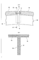
- FIG. 1 shows a structure of a turbine stationary blade seal plate according to an embodiment of the present invention, in which (A) is a cross-sectional view of an essential part taken along line AA in FIG. 3, and (B) is taken along line BB in (A). It is an expanded sectional view of the principal part in alignment.
- FIG. 1 shows a structure of a turbine stationary blade seal plate according to an embodiment of the present invention, in which (A) is a cross-sectional view of an essential part taken along line AA in FIG. 3, and (B) is taken along line BB in (A). It is an expanded sectional view of the principal part in alignment.
- FIG. 2 is a cross-sectional view taken along line CC in FIG. 3 and FIG. 7B is a cross-sectional view taken along line DD in FIG. 7; It is.
- the conventional turbine stationary blade is shown, (A) is sectional drawing of the principal part, (B) is an expanded sectional view of the principal part. It is a front view of the principal part of the conventional turbine stationary blade.
- Example shown below is a suitable specific example in the gas turbine of this invention, and there may be various technically preferable restrictions.
- the technical scope of the present invention is not limited to these embodiments unless specifically described to limit the present invention.
- the constituent elements in the embodiments shown below can be appropriately replaced with existing constituent elements and the like, and various variations including combinations with other existing constituent elements are possible. Therefore, the description of the embodiment described below does not limit the contents of the invention described in the claims.
- FIG. 1 is a longitudinal sectional view showing a schematic configuration of a gas turbine according to an embodiment of the present invention.
- a gas turbine 1 includes a compressor 2, a plurality of combustors 3, a turbine 4, and an exhaust chamber 5 from the upstream side in the supply / exhaust direction of compressed air C and combustion gas G to the downstream side.
- the compressor 2 generates compressed air C.
- the plurality of combustors 3 temporarily store the compressed air C supplied from the compressor 2 in the passenger compartment S, and further mix the compressed air C and fuel to generate a combustion gas G that is a working fluid.
- the turbine 4 generates rotational power by the combustion gas G supplied from the combustor 3.
- the exhaust chamber 5 exhausts the combustion gas G that has passed through the turbine 4.
- the gas turbine 1 includes a rotor 6 that rotates in the circumferential direction R of the turbine 4 with the axis O as the center of rotation.
- the turbine 4 includes a turbine stationary blade 8 and a turbine rotor blade 9 inside.
- the turbine stationary blades 8 and the turbine rotor blades 9 are alternately arranged along the axial direction of the rotor 6.
- the thermal energy of the combustion gas G is converted into rotational energy and taken out as electric power.
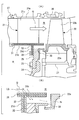
- FIG. 2A is a cross-sectional view of the main part showing an example of the turbine stationary blade 8 of such a gas turbine 1.
- the first-stage turbine stationary blade hereinafter referred to as “one-stage stationary blade” 8 connected to the uppermost stream side (left side in the drawing) to which the transition piece 3a of the combustor 3 is connected, and this A first stage turbine blade (hereinafter referred to as a “first stage blade”) 9 adjacent to the downstream side (right side in the drawing) of the first stage stationary blade 8 will be described as an example.
- the first stage stationary blade 8 is basically formed in an annular shape by arranging a plurality of the same segments along the turbine circumferential direction.
- the one-stage stationary blade 8 includes an outer shroud 8a that constitutes an outer peripheral wall, an inner shroud 8b that constitutes an inner peripheral wall, a blade body 8c that is constructed between the outer shroud 8a and the inner shroud 8b, and an inner shroud 8b. And a retainer 8d protruding from the back surface (lower side in the figure).
- the first stage stationary blade 8 abuts the downstream surface of the retainer 8 d against the support ring 10 and is fixed to the support ring 10 via a pin 11.
- the support ring 10 is fixed to the intermediate shaft cover 12 via bolts 13.
- the inner shroud 8b has one segment formed in a substantially parallelogram (diamond) in front view.
- Inner shrouds 8b of a plurality of segments are connected by a dividing surface so as to abut each other in the turbine circumferential direction.
- a horizontal seal plate 14 straddling between the butted end surfaces of the adjacent inner shrouds 8b is installed on the divided surface between the adjacent inner shrouds 8b so as to close the dividing gap K1 in the turbine circumferential direction of the inner shroud 8b. (See FIGS. 3 and 4A and 4B).
- the wing body 8c has an arc shape so as to be tapered toward the downstream side (right side in FIG. 3).
- one wing body 8c is provided for one inner shroud 8b.
- the retainer 8d extends in an annular shape along the circumferential direction of the turbine.
- the support ring 10 against which the downstream surface of the retainer 21d is abutted receives the load in the thrust direction (direction along the axis O serving as the rotor shaft) due to the differential pressure.
- the support ring 10 prevents the first stage stationary blade 8 from being displaced in a direction approaching the first stage moving blade 9.
- a vertical seal plate 15 extending between the butted end surfaces of the retainers 8d adjacent in the turbine circumferential direction is installed in the circumferential direction.
- the retainer 8d has a throat line P connecting the minimum inscribed circle SN formed between the adjacent blade main bodies 8c and the contacts X1 and X2 between the blade main bodies, and a dividing gap K1 between the adjacent inner shrouds 8b. It is arrange
- a seal member 16 such as an E-ring as a seal member is provided between the retainer 8d and the support ring 10 as shown in FIG.
- the retainer 8d and the support ring 10 function as a partition wall of the passenger compartment S.
- the casing S on the upstream side of the retainer 8d has a high pressure
- the space N on the downstream side of the retainer 8d has a low pressure.
- the pressure of the combustion gas G in the main flow path R passing through the blade body 8c is high on the upstream side of the throat line P, but the pressure is suddenly reduced on the downstream side of the throat line P, so that The interstage pressure between the stationary blade 8 and the one-stage moving blade 9 is almost the same pressure.
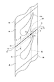
- FIG. 5 shows the specifics of the intersection point Q between the throat line P where the pressure of the combustion gas G changes and the dividing gap K1, and the intersection points T1, T2 between the retainer and the dividing gap K1, in contrast to the conventional turbine vane.
- the positional relationship is shown by a cross section in the rotor radial direction.
- FIG. 5A shows the positional relationship between the intersection point Q and the intersection point T1 in the present embodiment.
- FIG. 5B shows the positional relationship between the intersection point Q and the intersection point T2 in the conventional turbine vane.
- FIG. 5 the position of the intersection point Q in the combustion gas flow direction (rotor axial direction) (left and right direction on the paper surface in FIG. 5) is displayed so as to match in FIGS. 5A and 5B. is doing. Further, for convenience, a vertical line QV standing perpendicular to the rotor passing through the intersection point Q is indicated by a broken line.
- the pressure of the combustion gas G changes abruptly at the throat line P, but the pressure of the combustion gas in the vicinity of the division gap K1 may be considered to change along the division gap K1. Accordingly, the pressure of the combustion gas G along the dividing gap K1 in the vicinity of the dividing gap K1 is high on the upstream side at the intersection Q between the dividing gap K1 and the throat line P. descend.
- the intersection point T1 between the retainer 8d and the dividing gap K1 is disposed downstream of the intersection point Q.
- a division gap K1 on the downstream side from the intersection T1 is an area adjacent to the space N with the seal plate 14 interposed therebetween.
- intersection point T1 is arranged downstream of the intersection point Q (on the right side of the point Q on the paper surface).
- FIG. 7 displaying a conventional turbine vane
- an intersection T2 between the retainer 21d and the dividing gap K1 is disposed upstream of the throat line P.
- FIG. 5B which displays this in a cross section along the rotor axis direction
- the intersection point T2 is upstream of the intersection point Q (left side of the point Q on the paper surface). In the position of the intersection T2 shown in FIG.
- the retainer 8d is disposed downstream of the intersection point Q between the throat line P and the dividing gap K1, so that the pressure of the main flow path R downstream of the throat line P and the space N There is almost no pressure difference. Therefore, the amount of combustion gas that leaks from the main flow path R into the space N via the dividing gap K1 is reduced, so that the back surface of the inner shroud 8b and the support ring 10 are burned out and weld cracks are reduced.
- a seal member 16 accommodated in the seal groove 10a is interposed between the retainer 8d and the support ring 10. Therefore, the retainer 8d and the support ring 10 on the back surface side of the inner shroud 8b ensure the airtightness of the partition function that partitions the upstream side and the downstream side of the passenger compartment S, thereby preventing the loss of the passenger compartment air.
- the amount of combustion gas that leaks from the main flow path R into the space N via the division gap K1 by disposing the retainer 8d downstream of the intersection Q between the throat line P and the division gap K2. Therefore, it is possible to avoid burnout and weld cracking of the back surface of the inner shroud 8b and the upper portion of the support ring 10 (outside in the turbine radial direction). Therefore, the gas turbine 1 can be operated for a long time, and the reliability of the gas turbine 1 is improved.
- the turbine stationary blade and the gas turbine of the present invention it is possible to suppress breakage and cracking of components and welds arranged on the back side of the inner shroud due to leakage of high-temperature and high-pressure combustion gas.
- Gas turbine 8 Turbine stationary blade (single stage stationary blade) 8a ... outer shroud 8b ... inner shroud 8c ... wing body 8d ... retainer 8e ... rib 10 ... support ring 16 ... seal member (E-ring) G ... Combustion gas N ... Space P ... Throat line Q ... Intersection of throat line and split gap R ... Main flow path T1, T2 ... Intersection of retainer and split gap K1 ... Clearance (split gap)
Abstract
Description
図1において、ガスタービン1は、圧縮機2と、複数の燃焼器3と、タービン4と、排気室5と、を圧縮空気C及び燃焼ガスGの供給・排気方向の上流側から下流側に向けてこの順に備えている。圧縮機2は、圧縮空気Cを生成する。複数の燃焼器3は、圧縮機2から供給される圧縮空気Cを一旦車室Sに貯め、さらに圧縮空気Cと燃料とを混合して作動流体である燃焼ガスGを生成する。タービン4は、燃焼器3から供給される燃焼ガスGにより回転動力を発生させる。排気室5は、タービン4を通過した燃焼ガスGを排気する。また、ガスタービン1は、軸線Oを回転中心としてタービン4の周方向Rに回転するロータ6を備えている。
8…タービン静翼(一段静翼)
8a…外側シュラウド
8b…内側シュラウド
8c…翼本体
8d…リテーナ
8e…リブ
10…サポートリング
16…シール部材(Eリング)
G…燃焼ガス
N…空間
P…スロートライン
Q…スロートラインと分割隙間の交点
R…主流路
T1、T2…リテーナと分割隙間の交点
K1…隙間(分割隙間)
Claims (3)
- タービン周方向に沿って複数隣接して設けられると共に、主流路の外壁を構成する外側シュラウドと、
タービン周方向に沿って複数隣接して設けられると共に、前記主流路の内壁を構成する内側シュラウドと、
該前記内側シュラウドの表面から突出して前記主流路の上流側から下流側に向う燃焼ガスの流れを規定する翼本体と、
前記内側シュラウドの裏面から突出してタービン周方向に沿って延びるリテーナと、を備えるタービン静翼であって、
前記リテーナは、タービン周方向で隣接する前記翼本体の間に形成される最小内接円と前記翼本体それぞれとの接点間を結ぶスロートラインと、タービン周方向で隣接する前記内側シュラウドの分割隙間との交点よりも下流側に配置されているタービン静翼。 - 前記リテーナは、その下流側の面が突き当たるサポートリングを介してタービン本体に固定され、前記リテーナと前記サポートリングとの間にはシール部材が設けられている請求項1に記載のタービン静翼。
- 請求項1または請求項2のいずれか1項に記載のタービン静翼を備えるガスタービン。
Priority Applications (4)
| Application Number | Priority Date | Filing Date | Title |
|---|---|---|---|
| CN201280018906.5A CN103502577B (zh) | 2011-04-19 | 2012-01-20 | 涡轮静叶片及燃气轮机 |
| EP12773911.8A EP2700789A4 (en) | 2011-04-19 | 2012-01-20 | TURBINE STATOR DAWN AND GAS TURBINE |
| KR1020137024161A KR101531779B1 (ko) | 2011-04-19 | 2012-01-20 | 터빈 정익 및 가스 터빈 |
| JP2013510901A JP5848335B2 (ja) | 2011-04-19 | 2012-01-20 | タービン静翼およびガスタービン |
Applications Claiming Priority (2)
| Application Number | Priority Date | Filing Date | Title |
|---|---|---|---|
| JP2011-093045 | 2011-04-19 | ||
| JP2011093045 | 2011-04-19 |
Publications (1)
| Publication Number | Publication Date |
|---|---|
| WO2012144242A1 true WO2012144242A1 (ja) | 2012-10-26 |
Family
ID=47021475
Family Applications (1)
| Application Number | Title | Priority Date | Filing Date |
|---|---|---|---|
| PCT/JP2012/051198 WO2012144242A1 (ja) | 2011-04-19 | 2012-01-20 | タービン静翼およびガスタービン |
Country Status (6)
| Country | Link |
|---|---|
| US (1) | US20120269622A1 (ja) |
| EP (1) | EP2700789A4 (ja) |
| JP (1) | JP5848335B2 (ja) |
| KR (1) | KR101531779B1 (ja) |
| CN (1) | CN103502577B (ja) |
| WO (1) | WO2012144242A1 (ja) |
Cited By (2)
| Publication number | Priority date | Publication date | Assignee | Title |
|---|---|---|---|---|
| JP2017036710A (ja) * | 2015-08-11 | 2017-02-16 | 三菱日立パワーシステムズ株式会社 | 静翼、及びこれを備えているガスタービン |
| JP2019052639A (ja) * | 2017-09-15 | 2019-04-04 | ゼネラル・エレクトリック・カンパニイ・ポルスカ・エスピー・ズィーオー・オーGeneral Electric Company Polska Sp. Zo.O. | 傾斜した内側バンドフランジを有するタービンノズル |
Families Citing this family (4)
| Publication number | Priority date | Publication date | Assignee | Title |
|---|---|---|---|---|
| WO2015076906A2 (en) * | 2013-09-10 | 2015-05-28 | United Technologies Corporation | Plug seal for gas turbine engine |
| KR102084162B1 (ko) * | 2018-09-19 | 2020-03-03 | 두산중공업 주식회사 | 터빈 스테이터, 터빈 및 이를 포함하는 가스터빈 |
| US11215063B2 (en) * | 2019-10-10 | 2022-01-04 | General Electric Company | Seal assembly for chute gap leakage reduction in a gas turbine |
| KR102519905B1 (ko) | 2022-06-17 | 2023-04-11 | 최영환 | 프로펠러 감시 기능을 구비한 선박 |
Citations (9)
| Publication number | Priority date | Publication date | Assignee | Title |
|---|---|---|---|---|
| JPS4992415A (ja) * | 1972-09-05 | 1974-09-03 | ||
| JPS5316108A (en) * | 1976-07-29 | 1978-02-14 | Gen Electric | Fluiddcooled element |
| JPS5768103U (ja) * | 1980-10-13 | 1982-04-23 | ||
| JPH05187259A (ja) * | 1991-07-22 | 1993-07-27 | General Electric Co <Ge> | タービンノズル支持体 |
| JPH10266807A (ja) | 1997-03-27 | 1998-10-06 | Mitsubishi Heavy Ind Ltd | ガスタービンシール装置 |
| JP2000064807A (ja) * | 1998-08-20 | 2000-02-29 | General Electric Co <Ge> | 選択的断熱溶射皮膜を有する弓形ノズルベ―ン |
| US6481959B1 (en) * | 2001-04-26 | 2002-11-19 | Honeywell International, Inc. | Gas turbine disk cavity ingestion inhibitor |
| JP2006342804A (ja) * | 2005-06-06 | 2006-12-21 | General Electric Co <Ge> | 可変複合フィレットを備えたタービン翼形部 |
| US7534088B1 (en) * | 2006-06-19 | 2009-05-19 | United Technologies Corporation | Fluid injection system |
Family Cites Families (12)
| Publication number | Priority date | Publication date | Assignee | Title |
|---|---|---|---|---|
| US3752598A (en) * | 1971-11-17 | 1973-08-14 | United Aircraft Corp | Segmented duct seal |
| GB1605219A (en) * | 1975-10-02 | 1984-08-30 | Rolls Royce | Stator vane for a gas turbine engine |
| DE3003469A1 (de) * | 1980-01-31 | 1981-08-06 | MTU Motoren- und Turbinen-Union München GmbH, 8000 München | Einrichtung zur verbindung einander rotationssymmetrisch zugeordneter bauteile fuer stroemungsmaschinen, insbesondere gasturbinentriebwerke |
| US5174715A (en) * | 1990-12-13 | 1992-12-29 | General Electric Company | Turbine nozzle |
| US5154577A (en) * | 1991-01-17 | 1992-10-13 | General Electric Company | Flexible three-piece seal assembly |
| JP3782637B2 (ja) * | 2000-03-08 | 2006-06-07 | 三菱重工業株式会社 | ガスタービン冷却静翼 |
| US6752592B2 (en) * | 2001-12-28 | 2004-06-22 | General Electric Company | Supplemental seal for the chordal hinge seals in a gas turbine |
| JP4412081B2 (ja) * | 2004-07-07 | 2010-02-10 | 株式会社日立製作所 | ガスタービンとガスタービンの冷却方法 |
| US7172388B2 (en) * | 2004-08-24 | 2007-02-06 | Pratt & Whitney Canada Corp. | Multi-point seal |
| DE502006006344D1 (de) * | 2006-10-16 | 2010-04-15 | Siemens Ag | Turbinenschaufel für eine Turbine mit einem Kühlmittelkanal |
| US7798768B2 (en) * | 2006-10-25 | 2010-09-21 | Siemens Energy, Inc. | Turbine vane ID support |
| US8388307B2 (en) * | 2009-07-21 | 2013-03-05 | Honeywell International Inc. | Turbine nozzle assembly including radially-compliant spring member for gas turbine engine |
-
2012
- 2012-01-20 KR KR1020137024161A patent/KR101531779B1/ko active IP Right Grant
- 2012-01-20 EP EP12773911.8A patent/EP2700789A4/en not_active Withdrawn
- 2012-01-20 CN CN201280018906.5A patent/CN103502577B/zh active Active
- 2012-01-20 JP JP2013510901A patent/JP5848335B2/ja active Active
- 2012-01-20 WO PCT/JP2012/051198 patent/WO2012144242A1/ja active Application Filing
- 2012-01-24 US US13/357,179 patent/US20120269622A1/en not_active Abandoned
Patent Citations (9)
| Publication number | Priority date | Publication date | Assignee | Title |
|---|---|---|---|---|
| JPS4992415A (ja) * | 1972-09-05 | 1974-09-03 | ||
| JPS5316108A (en) * | 1976-07-29 | 1978-02-14 | Gen Electric | Fluiddcooled element |
| JPS5768103U (ja) * | 1980-10-13 | 1982-04-23 | ||
| JPH05187259A (ja) * | 1991-07-22 | 1993-07-27 | General Electric Co <Ge> | タービンノズル支持体 |
| JPH10266807A (ja) | 1997-03-27 | 1998-10-06 | Mitsubishi Heavy Ind Ltd | ガスタービンシール装置 |
| JP2000064807A (ja) * | 1998-08-20 | 2000-02-29 | General Electric Co <Ge> | 選択的断熱溶射皮膜を有する弓形ノズルベ―ン |
| US6481959B1 (en) * | 2001-04-26 | 2002-11-19 | Honeywell International, Inc. | Gas turbine disk cavity ingestion inhibitor |
| JP2006342804A (ja) * | 2005-06-06 | 2006-12-21 | General Electric Co <Ge> | 可変複合フィレットを備えたタービン翼形部 |
| US7534088B1 (en) * | 2006-06-19 | 2009-05-19 | United Technologies Corporation | Fluid injection system |
Non-Patent Citations (1)
| Title |
|---|
| See also references of EP2700789A4 * |
Cited By (3)
| Publication number | Priority date | Publication date | Assignee | Title |
|---|---|---|---|---|
| JP2017036710A (ja) * | 2015-08-11 | 2017-02-16 | 三菱日立パワーシステムズ株式会社 | 静翼、及びこれを備えているガスタービン |
| WO2017026314A1 (ja) * | 2015-08-11 | 2017-02-16 | 三菱日立パワーシステムズ株式会社 | 静翼、及びこれを備えているガスタービン |
| JP2019052639A (ja) * | 2017-09-15 | 2019-04-04 | ゼネラル・エレクトリック・カンパニイ・ポルスカ・エスピー・ズィーオー・オーGeneral Electric Company Polska Sp. Zo.O. | 傾斜した内側バンドフランジを有するタービンノズル |
Also Published As
| Publication number | Publication date |
|---|---|
| JPWO2012144242A1 (ja) | 2014-07-28 |
| KR20130129282A (ko) | 2013-11-27 |
| EP2700789A1 (en) | 2014-02-26 |
| CN103502577A (zh) | 2014-01-08 |
| CN103502577B (zh) | 2015-06-24 |
| JP5848335B2 (ja) | 2016-01-27 |
| EP2700789A4 (en) | 2015-03-18 |
| US20120269622A1 (en) | 2012-10-25 |
| KR101531779B1 (ko) | 2015-06-25 |
Similar Documents
| Publication | Publication Date | Title |
|---|---|---|
| JP5848439B2 (ja) | シール部材、タービン、及びガスタービン | |
| JP5848335B2 (ja) | タービン静翼およびガスタービン | |
| JP6633640B2 (ja) | 飛行機のタービンエンジンの噴射システムと燃料噴射ノズルの間の封止デバイス | |
| US20170009989A1 (en) | Gas turbine combustion chamber with integrated turbine inlet guide vane ring as well as method for manufacturing the same | |
| CN108930594B (zh) | 交叉涡轮发动机的空气轴承和热管理喷嘴布置 | |
| US10280798B2 (en) | Rotatable full ring fairing for a turbine engine | |
| EP2549121B1 (en) | Gas turbine engine comprising a stator vane assembly | |
| JP5885935B2 (ja) | タービン静翼およびガスタービン | |
| US9689272B2 (en) | Gas turbine and outer shroud | |
| WO2019131011A1 (ja) | 航空機用ガスタービン及び航空機用ガスタービンの動翼 | |
| US11067277B2 (en) | Component assembly for a gas turbine engine | |
| US11118469B2 (en) | Seal assembly for a turbo machine | |
| US20180045218A1 (en) | Shim for gas turbine engine | |
| WO2019187435A1 (ja) | 航空機用ガスタービン | |
| US20220243618A1 (en) | Outlet guide vane assembly in gas turbine engine | |
| US10968762B2 (en) | Seal assembly for a turbo machine | |
| US10774661B2 (en) | Shroud for a turbine engine | |
| JP2009215897A (ja) | ガスタービンエンジン | |
| JP2020094508A (ja) | タービン静翼及びガスタービン | |
| US20140154060A1 (en) | Turbomachine seal assembly and method of sealing a rotor region of a turbomachine |
Legal Events
| Date | Code | Title | Description |
|---|---|---|---|
| 121 | Ep: the epo has been informed by wipo that ep was designated in this application |
Ref document number: 12773911 Country of ref document: EP Kind code of ref document: A1 |
|
| ENP | Entry into the national phase |
Ref document number: 2013510901 Country of ref document: JP Kind code of ref document: A |
|
| ENP | Entry into the national phase |
Ref document number: 20137024161 Country of ref document: KR Kind code of ref document: A |
|
| WWE | Wipo information: entry into national phase |
Ref document number: 2012773911 Country of ref document: EP |
|
| NENP | Non-entry into the national phase |
Ref country code: DE |