WO2012144097A1 - ワイヤハーネス用プロテクタ - Google Patents
ワイヤハーネス用プロテクタ Download PDFInfo
- Publication number
- WO2012144097A1 WO2012144097A1 PCT/JP2011/073561 JP2011073561W WO2012144097A1 WO 2012144097 A1 WO2012144097 A1 WO 2012144097A1 JP 2011073561 W JP2011073561 W JP 2011073561W WO 2012144097 A1 WO2012144097 A1 WO 2012144097A1
- Authority
- WO
- WIPO (PCT)
- Prior art keywords
- wire harness
- flat plate
- protector
- concave
- convex
- Prior art date
- Legal status (The legal status is an assumption and is not a legal conclusion. Google has not performed a legal analysis and makes no representation as to the accuracy of the status listed.)
- Ceased
Links
Images



Classifications
-
- B—PERFORMING OPERATIONS; TRANSPORTING
- B60—VEHICLES IN GENERAL
- B60R—VEHICLES, VEHICLE FITTINGS, OR VEHICLE PARTS, NOT OTHERWISE PROVIDED FOR
- B60R16/00—Electric or fluid circuits specially adapted for vehicles and not otherwise provided for; Arrangement of elements of electric or fluid circuits specially adapted for vehicles and not otherwise provided for
- B60R16/02—Electric or fluid circuits specially adapted for vehicles and not otherwise provided for; Arrangement of elements of electric or fluid circuits specially adapted for vehicles and not otherwise provided for electric constitutive elements
- B60R16/0207—Wire harnesses
- B60R16/0215—Protecting, fastening and routing means therefor
-
- H—ELECTRICITY
- H02—GENERATION; CONVERSION OR DISTRIBUTION OF ELECTRIC POWER
- H02G—INSTALLATION OF ELECTRIC CABLES OR LINES, OR OF COMBINED OPTICAL AND ELECTRIC CABLES OR LINES
- H02G3/00—Installations of electric cables or lines or protective tubing therefor in or on buildings, equivalent structures or vehicles
- H02G3/02—Details
- H02G3/04—Protective tubing or conduits, e.g. cable ladders or cable troughs
- H02G3/0462—Tubings, i.e. having a closed section
- H02G3/0487—Tubings, i.e. having a closed section with a non-circular cross-section
-
- H—ELECTRICITY
- H02—GENERATION; CONVERSION OR DISTRIBUTION OF ELECTRIC POWER
- H02G—INSTALLATION OF ELECTRIC CABLES OR LINES, OR OF COMBINED OPTICAL AND ELECTRIC CABLES OR LINES
- H02G3/00—Installations of electric cables or lines or protective tubing therefor in or on buildings, equivalent structures or vehicles
- H02G3/02—Details
- H02G3/04—Protective tubing or conduits, e.g. cable ladders or cable troughs
- H02G3/0406—Details thereof
- H02G3/0418—Covers or lids; Their fastenings
Definitions
- the present invention relates to a protector for a wire harness.
- the protector for a wire harness described in Patent Document 1 is made of a resin, and is configured by a flat plate including a main body portion through which the wire harness is inserted and a lid portion that covers the main body portion and closes the opening surface thereof.
- a flat plate including a main body portion through which the wire harness is inserted and a lid portion that covers the main body portion and closes the opening surface thereof.
- Each recessed part is a slanting straight narrow groove, and has the same shape.
- the present invention has been completed based on the above circumstances, and an object of the present invention is to provide a wire harness protector that realizes weight reduction and ensures a predetermined rigidity.
- the invention of claim 1 is a protector made of resin for protecting a wire harness, and covers a main body portion through which the wire harness is inserted and an opening surface of the main body portion.
- a flat plate having an edge convex portion that defines a missing portion of the concave portion is provided.
- the weight of the flat plate can be reduced, and the incomplete recesses can be formed by the edge protrusions on the outer edge of the flat plate.
- partitioning the rigidity of the flat plate can be ensured.
- the present invention may further have the following configuration.
- the plurality of concave portions and the convex portions are formed on the inner surface of the flat plate. This prevents foreign matter such as dust from accumulating in the recess.
- the plurality of concave portions and the convex portions are formed on both the main body portion and the lid portion. If it carries out like this, the whole flat plate can be reduced in weight sufficiently.
- the said convex part is made into the rib shape form which surrounds the circumference
- the plurality of recesses are repeatedly arranged over almost the entire surface of at least one surface of the flat plate.
- the edge convex portion is formed linearly along the outer edge of the flat plate. If it carries out like this, the rigidity of the outer edge of a flat plate will be improved more.
- the complete recess is circular. In this case, since the corner portion is eliminated from the complete recess, it is possible to prevent a change in performance due to the lack of the corner portion.
- the incomplete concave portion is bordered by an arc-shaped arc portion and an arc-shaped portion formed by connecting both ends of the arc portion linearly.
- the structure of the mold for forming the incomplete recess is not particularly complicated.
- the complete recess has a hexagonal shape.
- a large number of complete recesses can be closely arranged on at least one surface of the flat plate.
- the plurality of concave portions and the convex portions have a honeycomb structure as a whole. If it carries out like this, the request
- a protector for a wire harness that realizes weight reduction and ensures a predetermined rigidity.
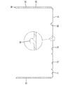
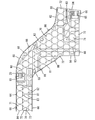
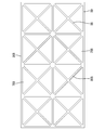
- FIG. 3 is a sectional view taken along line XX in FIG. 2. It is a bottom view of a cover part. It is a bottom view of the cover part of the protector for wire harnesses which concerns on Embodiment 2. FIG. It is a bottom view of the cover part of the protector for wire harnesses which concerns on a reference example.
- the wire harness protector 10 protects the wire harness 90 and includes a flat plate 20 including a main body 30 and a lid 60.
- the flat plate 20 is made of a resin such as polypropylene having a low specific gravity.
- the flat plate 20 is configured to extend in the front-rear direction as a whole while being bent substantially in an S shape.
- the main body 30 has a substantially square concave cross section as a whole, and includes a bottom plate 31 and a pair of side plates 32 rising from both side edges of the bottom plate 31.
- An insertion space into which the wire harness 90 is inserted is formed in the main body 30. Then, the wire harness 90 is placed on the inner surface of the bottom plate 31, and the wire harness 90 is brought into contact with the inner surfaces of the both side plates 32 from the inside to define the wiring direction.
- the main body portion 30 intersects the obtuse angle with the first insertion portion 33 that extends substantially straight in the front-rear direction and the front portion of the first insertion portion 33 obliquely forward.
- the second insertion portion 34 extends and a third insertion portion 35 that intersects the obtuse angle with the front portion of the second insertion portion 34 and extends substantially straight in the front-rear direction.
- Both front and rear ends of the first insertion part 33 and the front end of the third insertion part 35 are opened as openings 36A, 36B, and 36C.
- the wiring path of the wire harness 90 includes a path that is routed substantially straight through the openings 36A and 36B before and after the first insertion part 33, and an opening 36A and a third insertion part 35 at the rear end of the first insertion part 33. It is possible to select a route that is shifted and arranged in the width direction through the opening 36C at the front end.
- the main body 30 is formed with a mounting portion 37 between the first and second insertion portions 33 and 34 so that a fixing tool such as a clip (not shown) can be mounted.
- a plurality of lock receiving portions 38 are formed on the upper edge of the side plates 32 with a predetermined interval.
- Each lock receiving portion 38 has a portal frame shape, and a slit-like lock space is formed therein.
- the lid 60 is put on the main body 30 so as to cover the upper opening surface of the main body 30.
- the lid 60 has a single-plate-like lid main body 61 that is attached to the main body 30 and is disposed at a position facing the bottom plate 31 and placed on the upper edge of the side plates 32. Yes.
- the lid main body 61 includes a first lid 62 that extends substantially straight in the front-rear direction, and a second lid 63 that intersects the obtuse angle with the front of the first lid 62 and extends obliquely forward.
- the third lid body 64 includes a front portion of the second lid body 63 and a third lid body 64 that intersects an obtuse angle and extends substantially straight in the front-rear direction.
- a mounting portion 65 to which a fixture can be mounted is formed so as to protrude outward.
- the protector 10 is fixed to the attachment object by attaching the fixture to the attachment parts 37 and 65 and attaching the fixture to the attachment object such as the vehicle body.
- a plurality of lock portions 66 are formed on both side edges of the lid portion main body 61 so as to hang down at positions corresponding to the lock receiving portions 38. As shown in FIG. 1, a lock claw 68 is formed at the tip of each lock portion 66 so as to protrude outward.
- each lock portion 66 is inserted into the lock space of the lock receiving portion 38, and the lock claw 68 elastically locks the lock receiving portion 38.
- the lid 60 is held closed with respect to the main body 30.
- edge ribs 69 are formed on the outer edge of the lid main body 61 so as to protrude downward except for positions corresponding to the openings 36A, 36B, 36C. The edge ribs 69 are overlapped on the outer sides of the side plates 32 with the lid closed.
- a plurality of recesses 70 are formed on the inner surface of the lid main body 61 and the inner surface of the bottom plate 31, that is, the inner surface of the flat plate 20.
- the concave portions 70 are repeatedly arranged in alignment over almost the entire inner surface of the flat plate 20.
- convex portions 80 that partition the periphery of the concave portions 70 are formed.
- the convex portion 80 is in the form of a rib that surrounds the periphery of each concave portion 70 over the entire circumference.
- Each recess 70 has a circular shape having a predetermined shape, specifically, a perfect circular recess 71 having a perfect circle shape, and is not a predetermined shape, that is, a shape different from the complete recess 71 and is a part of the complete recess 71. And an incomplete recess 72 formed by lacking.
- a plurality of complete recesses 71 are arranged side by side along the front-rear direction on the inner side of the flat plate 20, and are shifted in a staggered manner in the width direction.
- the incomplete recess 72 includes an arc-shaped arc 73 and a chord 74 formed by connecting both ends of the arc 73 linearly.
- a plurality of incomplete recesses 72 are arranged along the outer edge of the flat plate 20.
- Each incomplete recess 72 is composed of a plurality of types such as a quadrant or a semicircular arc according to the difference in the amount of missing from each complete recess 71 serving as a base.
- the incomplete recess 72 is also formed on the periphery of the mounting portions 37 and 65.
- the convex portion 80 includes an inner convex portion 83 that divides the arcuate portion 73 of the complete recess portion 71 and the incomplete recess portion 72 inside the flat plate 20, and a string-like portion 74 of the incomplete recess portion 72 at the outer edge of the flat plate 20. It has the edge convex part 84 which divides (missing part).
- the edge convex part 84 is made into the form extended linearly along the outer edge (part corresponding to opening part 36A, 36B, 36C) of the flat plate 20.
- FIG. The incomplete recess 72 is also partitioned by the edge rib 69 and the side plate 32 in addition to the edge protrusion 84.
- each recess 70 is a substantially flat flat surface.
- the thickness of the bottom plate 31 corresponding to each concave portion 70 is made thinner than the thickness of the side plate 32, and the thickness of the bottom plate 31 corresponding to the convex portion 80 is made thicker than the thickness of the side plate 32.
- the thickness of the bottom plate 31 corresponding to each recess 70 is approximately half of the protrusion amount of the protrusion 80.
- the weight of the flat plate 20 is reduced by each concave portion 70, so that the weight of the flat plate 20 is reduced. Further, the rigidity of the flat plate 20 is ensured by the convex portion 80.
- the edge convex part 84 is arrange
- the rigidity in the outer edge of the flat plate 20 is improved. Since the incomplete concave portion 72 is arranged on the outer edge side of the flat plate 20 and is partitioned by the edge convex portion 84, the inner surface on the outer edge side of the flat plate 20 is sufficiently thinned, and the weight of the flat plate 20 is reduced. The Therefore, according to this embodiment, the protector 10 in which weight reduction is realized and predetermined rigidity is ensured is provided.
- FIG. 5 shows a second embodiment of the present invention.
- the form of each concave portion 70A and convex portion 80A is different from that of the first embodiment.
- Each recess 70A is a hexagon having a predetermined shape, more specifically, a regular hexagon complete recess 71A, and a polygon that is different from the complete recess 71A and lacks a part of the complete recess 71A.
- the incomplete recess 72A A plurality of complete recesses 71A are arranged inside the flat plate 20A, and a plurality of incomplete recesses 72A are arranged along the outer edge of the flat plate 20A.
- Each incomplete recess 72A is composed of a plurality of types such as a triangle (for example, an isosceles triangle) and a trapezoid (for example, an isosceles trapezoid) depending on a difference in the amount of missing from each complete recess 71A as a base.
- each recessed part 70A is repeatedly formed in alignment over the whole inner surface of the flat plate 20A, and has taken the honeycomb structure as a whole with the convex part 80A.
- the convex portion 80A is formed in a rib shape having substantially the same thickness as a whole, and a honeycomb-shaped inner convex portion 83A that partitions a part of the complete recess portion 71A and the incomplete recess portion 72A inside the flat plate 20A, and a flat plate It has a frame-like edge convex part 84A that defines the missing part of the incomplete concave part 72A by surrounding the outer edge of 20A over the entire circumference.
- the honeycomb structure including the concave portions 70A and the convex portions 80A is formed on the entire inner surface of the flat plate 20A, the rigidity of the flat plate 20A is increased.
- the same effects as those of the first embodiment can be enjoyed.
- FIG. 6 shows a reference example.
- a plurality of concave portions 70B and convex portions 80B are formed in alignment on the inner surface of the flat plate 20B.
- Each of the concave portions 70B has the same shape, and has a triangular shape as a whole, specifically an isosceles triangle.
- the four recesses 70B are arranged concentrically with their vertices facing each other.
- the convex portion 80B is in the form of a rib that divides each concave portion 70B over the entire circumference on the inner surface of the flat plate 20B.
- the convex portion 80B includes a unit composed of an X-shaped bracing portion 88 that partitions the oblique side of each concave portion 70B and a rectangular frame portion 89 that defines the bottom side of each concave portion 70B. And a plurality of them arranged in the width direction.
- the weight of the flat plate 20B can be reduced by the concave portions 70B, and the rigidity of the flat plate 20B can be secured by the convex portions 80B.
- Each concave part and convex part may be formed only on either one of the front and back surfaces of a flat plate.
- Each recessed part and convex part may be formed only in any one of a main-body part and a cover part.
- Each recessed part and convex part may make a different shape between the lid part and the main body part.
- the complete recess may be a polygon other than a hexagon.
- the shape and type of the protector are arbitrary.
- the lid may be integrally connected to the main body via a hinge, and a plurality of lids are attached to one main body. Also good.
Landscapes
- Engineering & Computer Science (AREA)
- Architecture (AREA)
- Civil Engineering (AREA)
- Structural Engineering (AREA)
- Mechanical Engineering (AREA)
- Details Of Indoor Wiring (AREA)
Abstract
軽量化を実現するとともに、所定の剛性を確保したワイヤハーネス用プロテクタを提供する。 プロテクタ(10)の平板(20)の少なくとも一面には、複数の凹部(70)と、各凹部(70)の周囲を区画する凸部(80)とが形成されている。各凹部(70)は、所定形状をなす完全形凹部(71)と、所定形状をなさずに完全形凹部(71)の一部を欠落してなる不完全形凹部(72)とを有する。凸部(80)は、平板(20)の外縁に配置される端縁凸部(84)を有する。端縁凸部(84)は、不完全形凹部(72)の欠落部分を区画している。
Description
本発明は、ワイヤハーネス用プロテクタに関する。
特許文献1に記載のワイヤハーネス用プロテクタは、樹脂製であって、ワイヤハーネスを挿通する本体部と、本体部に被さってその開口面を閉じる蓋部とからなる平板で構成されている。平板(本体部及び蓋部)の外面には、複数の凹部が肉抜きにより形成されている。各凹部は、斜め直線状の細溝であって、互いに同形とされている。
ところで、上記従来のプロテクタの場合、各凹部によって平板の軽量化を実現することが可能であり、かつ各凹部の周囲を区画する凸部によって平板の剛性を確保することが可能であった。しかし、平板の外面に占める各凹部の占有面積が大きいと、凸部の占有面積が相対的に小さくなって、平板の剛性が低下する一方、平板の外面に占める各凹部の占有面積が小さいと、凸部の占有面積が相対的に大きくなって、平板の軽量化を実現するのが困難になるという事情があった。
本発明は上記のような事情に基づいて完成されたものであって、軽量化を実現するとともに、所定の剛性を確保したワイヤハーネス用プロテクタを提供することを目的とする。
上記の目的を達成するための手段として、請求項1の発明は、ワイヤハーネスを保護する樹脂製のプロテクタであって、前記ワイヤハーネスが挿通される本体部と前記本体部に被さってその開口面を閉じる蓋部とからなる板状の形態をなし、内外両面のうちの少なくとも一面に、複数の凹部と、前記複数の凹部の周囲を区画する凸部とが形成され、前記複数の凹部が、所定形状をなす完全形凹部と、前記完全形凹部の一部を欠落してなる完全形凹部とは異形の不完全形凹部とを有し、さらに、前記凸部が、外縁において前記不完全形凹部の欠落部分を区画する端縁凸部を有する平板を備えているところに特徴を有する。
このように、複数の凹部が完全形凹部ばかりでなく不完全形凹部を有することにより、平板の軽量化を実現することができ、さらに、不完全形凹部が平板の外縁で端縁凸部によって区画されることにより、平板の剛性を確保することができる。
このように、複数の凹部が完全形凹部ばかりでなく不完全形凹部を有することにより、平板の軽量化を実現することができ、さらに、不完全形凹部が平板の外縁で端縁凸部によって区画されることにより、平板の剛性を確保することができる。
また、本発明は、さらに次のような構成をとり得る。
(1)前記複数の凹部及び前記凸部が、前記平板の内面に形成されている。こうすると、凹部に塵埃等の異物が堆積するのが防止される。
(2)前記複数の凹部及び前記凸部が、前記本体部と前記蓋部の両方に形成されている。こうすると、平板全体を充分に軽量化することができる。
(3)前記凸部が、前記複数の凹部の周囲を全周に亘って取り囲むリブ状の形態とされている。こうすると、平板の剛性がより高められる。
(4)前記複数の凹部が、前記平板の少なくとも一面のほぼ全面に亘って繰り返して配置されている。こうすると、平板を充分に軽量化することができるとともに、平板の剛性も充分に確保することができる。
(5)前記端縁凸部が、前記平板の前記外縁に沿って直線状に形成されている。こうすると、平板の外縁の剛性がより高められる。
(6)前記完全形凹部が、円形をなしている。こうすると、完全形凹部から角部が無くなるので、角部が欠けることに起因する性能変化を防止することができる。
(7)前記不完全形凹部が、円弧形の円弧部と、前記円弧部の両端を直線状に結んでなる弧状部とによって縁取られている。これによれば、不完全形凹部を成形する金型の構造が格別複雑になることもない。
(8)前記完全形凹部が、六角形をなしている。こうすると、平板の少なくとも一面に多数の完全形凹部を緊密に配置させることができる。
(9)前記複数の凹部及び前記凸部が、全体としてハニカム構造をとっている。こうすると、平板の軽量化及び高剛性化の要求に充分に応えることができる。
(1)前記複数の凹部及び前記凸部が、前記平板の内面に形成されている。こうすると、凹部に塵埃等の異物が堆積するのが防止される。
(2)前記複数の凹部及び前記凸部が、前記本体部と前記蓋部の両方に形成されている。こうすると、平板全体を充分に軽量化することができる。
(3)前記凸部が、前記複数の凹部の周囲を全周に亘って取り囲むリブ状の形態とされている。こうすると、平板の剛性がより高められる。
(4)前記複数の凹部が、前記平板の少なくとも一面のほぼ全面に亘って繰り返して配置されている。こうすると、平板を充分に軽量化することができるとともに、平板の剛性も充分に確保することができる。
(5)前記端縁凸部が、前記平板の前記外縁に沿って直線状に形成されている。こうすると、平板の外縁の剛性がより高められる。
(6)前記完全形凹部が、円形をなしている。こうすると、完全形凹部から角部が無くなるので、角部が欠けることに起因する性能変化を防止することができる。
(7)前記不完全形凹部が、円弧形の円弧部と、前記円弧部の両端を直線状に結んでなる弧状部とによって縁取られている。これによれば、不完全形凹部を成形する金型の構造が格別複雑になることもない。
(8)前記完全形凹部が、六角形をなしている。こうすると、平板の少なくとも一面に多数の完全形凹部を緊密に配置させることができる。
(9)前記複数の凹部及び前記凸部が、全体としてハニカム構造をとっている。こうすると、平板の軽量化及び高剛性化の要求に充分に応えることができる。
本発明によれば、軽量化を実現するとともに、所定の剛性を確保したワイヤハーネス用プロテクタが提供される。
<実施形態1>
本発明の実施形態1を図1ないし図4によって説明する。本実施形態に係るワイヤハーネス用プロテクタ10は、ワイヤハーネス90を保護するものであって、本体部30と蓋部60とからなる平板20を備えている。平板20は、比重の軽いポリプロピレン等の樹脂で構成されている。本実施形態の場合、平板20は、ほぼS字形に屈曲しつつ全体として前後方向に延びる形態とされている。
本発明の実施形態1を図1ないし図4によって説明する。本実施形態に係るワイヤハーネス用プロテクタ10は、ワイヤハーネス90を保護するものであって、本体部30と蓋部60とからなる平板20を備えている。平板20は、比重の軽いポリプロピレン等の樹脂で構成されている。本実施形態の場合、平板20は、ほぼS字形に屈曲しつつ全体として前後方向に延びる形態とされている。
本体部30は、図3に示すように、全体として断面略角凹状をなし、底板31と底板31の両側縁から立ち上がる一対の側板32とを有している。本体部30内には、ワイヤハーネス90が挿通される挿通空間が形成されている。そして、底板31の内面にはワイヤハーネス90が載せられ、両側板32の内面にはワイヤハーネス90が内側から当接されてその配索方向が規定される。
具体的には、本体部30は、図1及び図2に示すように、前後方向にほぼ真直ぐ延びる第1挿通部33と、第1挿通部33の前部と鈍角に交差して斜め前方に延びる第2挿通部34と、第2挿通部34の前部と鈍角に交差して前後方向にほぼ真直ぐ延びる第3挿通部35とからなる。第1挿通部33の前後両端及び第3挿通部35の前端は開口部36A、36B、36Cとして開口されている。ワイヤハーネス90の配索経路は、第1挿通部33の前後の開口部36A、36Bを通してほぼ真直ぐ配索される経路と、第1挿通部33の後端の開口部36A及び第3挿通部35の前端の開口部36Cを通して幅方向にシフトして配索される経路とに選択可能とされている。
本体部30には、第1、第2挿通部33、34間に、図示しないクリップ等の固定具を装着可能な装着部37が外側に突出して形成されている。また、両側板32の上端縁には、所定間隔をかけて複数のロック受け部38が形成されている。各ロック受け部38は、門型枠状をなし、その内部に、スリット状のロック空間が形成されている。
蓋部60は、本体部30の上方開口面を覆うように本体部30に被せ付けられる。そして、蓋部60は、本体部30に取り付けられた状態で、底板31と対向する位置に配置され、かつ両側板32の上端縁に載せられる一枚板状の蓋部本体61を有している。蓋部本体61は、図4に示すように、前後方向にほぼ真直ぐ延びる第1蓋体62と、第1蓋体62の前部と鈍角に交差して斜め前方に延びる第2蓋体63と、第2蓋体63の前部と鈍角に交差して前後方向にほぼ真直ぐ延びる第3蓋体64とからなる。第1、第3蓋体62、64には、固定具を装着可能な装着部65が外側に突出して形成されている。固定具が装着部37、65に装着され、かつ車体等の取付対象に取り付けられることにより、プロテクタ10が取付対象に固定されるようになっている。また、蓋部本体61の両側縁には、各ロック受け部38と対応する位置に、複数のロック部66が垂下して形成されている。各ロック部66の先端部には、図1に示すように、ロック爪68が外側に突出して形成されている。ここで、本体部30の上方開口面が蓋部60によって閉止され、各ロック部66がロック受け部38のロック空間内に挿入され、かつロック爪68がロック受け部38を弾性的に係止することにより、蓋部60が本体部30に対して閉じ状態に保持される。さらに、蓋部本体61の外縁には、開口部36A、36B、36Cと対応する位置を除いて端縁リブ69が下側へ突出して形成されている。端縁リブ69は、蓋閉め状態で両側板32の外側に重ねられる。
さて、蓋部本体61の内面及び底板31の内面、つまり平板20の内面には、図2及び図4に示すように、複数の凹部70が形成されている。各凹部70は、平板20の内面のほぼ全面に亘って繰り返して整列に配置されている。また、平板20の内面には、各凹部70の周囲を区画する凸部80が形成されている。かかる凸部80は、各凹部70の周囲を全周に亘って取り囲むリブ状の形態とされている。
そして、各凹部70は、所定形状となる円形、詳細には真円形の完全形凹部71と、所定形状ではない、つまり完全形凹部71とは異形の形状であって完全形凹部71の一部を欠落してなる不完全形凹部72とからなる。完全形凹部71は、平板20の内側において、前後方向に沿って複数並んで配置され、幅方向では千鳥にシフトして配置されている。
不完全形凹部72は、円弧形の円弧部73と、円弧部73の両端を直線状に結んでなる弦状部74とからなる。そして、不完全形凹部72は、平板20の外縁に沿って複数並んで配置されている。各不完全形凹部72は、母体となる各完全形凹部71に対する欠落量の違いに応じ、四半円弧状又は半円弧状等の複数種で構成されている。なお、不完全形凹部72は、装着部37、65の周縁にも形成されている。
また、凸部80のうち、前後方向及び幅方向で向き合う3つの凹部70間に位置する部分は厚肉の厚肉部81とされ、前後方向で並び合う2つの凹部70間に位置する部分は薄肉の薄肉部82とされている。そして、凸部80は、平板20の内側において完全形凹部71及び不完全形凹部72の円弧部73を区画する内側凸部83と、平板20の外縁において不完全形凹部72の弦状部74(欠落部分)を区画する端縁凸部84とを有している。端縁凸部84は、平板20の外縁(開口部36A、36B、36Cと対応する部分)に沿って直線状に延びる形態とされている。なお、不完全形凹部72は端縁凸部84以外に端縁リブ69及び側板32によっても区画されている。
図3に示すように、各凹部70の底面は、ほぼ平坦なフラット面とされている。そして、各凹部70に対応する底板31の厚みは、側板32の厚みよりも薄くされ、凸部80と対応する底板31の厚みは、側板32の厚みよりも厚くされている。本実施形態の場合、各凹部70と対応する底板31の厚みは、凸部80の突出量の概ね半分とされている。
本実施形態によれば、各凹部70によって平板20の重量が減少するため、平板20の軽量化が実現される。また、凸部80によって平板20の剛性が確保される。この場合に、端縁凸部84が平板20の外縁に沿って配置されているため、平板20の外縁における剛性が高められる。そして、不完全形凹部72が平板20の外縁側に配置されて端縁凸部84で区画されているため、平板20の外縁側の内面が充分に肉抜きされ、平板20の重量が軽減される。したがって、本実施形態によれば、軽量化が実現され、かつ所定の剛性が確保されたプロテクタ10が提供される。
<実施形態2>
図5は、本発明の実施形態2を示す。実施形態2では、各凹部70A及び凸部80Aの形態が実施形態1とは異なっている。
図5は、本発明の実施形態2を示す。実施形態2では、各凹部70A及び凸部80Aの形態が実施形態1とは異なっている。
各凹部70Aは、所定形状となる六角形、詳細には正六角形の完全形凹部71Aと、完全形凹部71Aとは異形の形状であって完全形凹部71Aの一部を欠落してなる多角形の不完全形凹部72Aとからなる。完全形凹部71Aは平板20Aの内側に複数配置され、不完全形凹部72Aは平板20Aの外縁に沿って複数配置されている。各不完全形凹部72Aは、母体となる各完全形凹部71Aに対する欠落量の違いに応じ、三角形(例えば二等辺三角形)、台形(例えば等脚台形)等の複数種で構成されている。そして、各凹部70Aは、平板20Aの内面の全面に亘って繰り返して整列に形成され、凸部80Aとともに全体としてハニカム構造をとっている。
凸部80Aは、全体にほぼ同じ厚みを有するリブ状の形態とされ、平板20Aの内側において完全形凹部71A及び不完全形凹部72Aの一部を区画するハニカム状の内側凸部83Aと、平板20Aの外縁を全周に亘って取り囲むことで不完全形凹部72Aの欠落部分を区画する枠状の端縁凸部84Aとを有している。実施形態2によれば、平板20Aの内面全体に凹部70A及び凸部80Aからなるハニカム構造が形成されているため、平板20Aの剛性が高められる。その他、実施形態2によれば、実施形態1と同様の効果を享受し得る。
<参考例>
図6は、参考例を示す。参考例では、平板20Bの内面に、複数の凹部70B及び凸部80Bが整列して形成されている。各凹部70Bは、いずれも同形であって全体として三角形、詳細には二等辺三角形をなしている。ここでは、4つの凹部70Bが互いの頂点を向き合わせて同心状に配置されている。
図6は、参考例を示す。参考例では、平板20Bの内面に、複数の凹部70B及び凸部80Bが整列して形成されている。各凹部70Bは、いずれも同形であって全体として三角形、詳細には二等辺三角形をなしている。ここでは、4つの凹部70Bが互いの頂点を向き合わせて同心状に配置されている。
凸部80Bは、平板20Bの内面において各凹部70Bを全周に亘って区画するリブ状の形態とされている。具体的には、凸部80Bは、各凹部70Bの斜辺を区画するX字状の筋交部88と、各凹部70Bの底辺を区画する方形状の枠部89とからなるユニットが、前後方向及び幅方向に複数整列してなるものである。この参考例によっても、各凹部70Bによって平板20Bの軽量化を図れるとともに、凸部80Bによって平板20Bの剛性を確保することが可能となる。
<他の実施形態>
本発明は上記記述及び図面によって説明した実施形態に限定されるものではなく、例えば次のような実施形態も本発明の技術的範囲に含まれる。
(1)各凹部及び凸部が、平板の表裏両面のいずれか一面のみに形成されるものであってもよい。
(2)各凹部及び凸部が、本体部と蓋部のいずれか一方のみに形成されるものであってもよい。
(3)各凹部及び凸部が、蓋部と本体部とで異なる形状をなすものであってもよい。
(4)完全形凹部が、六角形以外の多角形であってもよい。
(5)プロテクタの形状、種類は任意であり、例えば、蓋部がヒンジを介して本体部に一体に連結されていてもよく、また、複数の蓋部が一つの本体部に取り付けられていてもよい。
本発明は上記記述及び図面によって説明した実施形態に限定されるものではなく、例えば次のような実施形態も本発明の技術的範囲に含まれる。
(1)各凹部及び凸部が、平板の表裏両面のいずれか一面のみに形成されるものであってもよい。
(2)各凹部及び凸部が、本体部と蓋部のいずれか一方のみに形成されるものであってもよい。
(3)各凹部及び凸部が、蓋部と本体部とで異なる形状をなすものであってもよい。
(4)完全形凹部が、六角形以外の多角形であってもよい。
(5)プロテクタの形状、種類は任意であり、例えば、蓋部がヒンジを介して本体部に一体に連結されていてもよく、また、複数の蓋部が一つの本体部に取り付けられていてもよい。
10…ワイヤハーネス用プロテクタ
20、20A…平板
30…本体部
60…蓋部
70、70A…凹部
71、71A…完全形凹部
72、72B…不完全形凹部
80、80A…凸部
84、84A…端縁凸部
90…ワイヤハーネス
20、20A…平板
30…本体部
60…蓋部
70、70A…凹部
71、71A…完全形凹部
72、72B…不完全形凹部
80、80A…凸部
84、84A…端縁凸部
90…ワイヤハーネス
Claims (10)
- ワイヤハーネスを保護する樹脂製のプロテクタであって、
前記ワイヤハーネスが挿通される本体部と前記本体部に被さってその開口面を閉じる蓋部とからなる板状の形態をなし、内外両面のうちの少なくとも一面に、複数の凹部と、前記複数の凹部の周囲を区画する凸部とが形成され、前記複数の凹部が、所定形状をなす完全形凹部と、前記完全形凹部の一部を欠落してなる完全形凹部とは異形の不完全形凹部とを有し、さらに、前記凸部が、外縁において前記不完全形凹部の欠落部分を区画する端縁凸部を有する平板を備えていることを特徴とするワイヤハーネス用プロテクタ。 - 前記複数の凹部及び前記凸部が、前記平板の内面に形成されていることを特徴とする請求項1記載のワイヤハーネス用プロテクタ。
- 前記複数の凹部及び前記凸部が、前記本体部と前記蓋部の両方に形成されていることを特徴とする請求項1又は2記載のワイヤハーネス用プロテクタ。
- 前記凸部が、前記複数の凹部の周囲を全周に亘って取り囲むリブ状の形態とされていることを特徴とする請求項1ないし3のいずれか1項記載のワイヤハーネス用プロテクタ。
- 前記複数の凹部が、前記平板の少なくとも一面のほぼ全面に亘って繰り返して配置されていることを特徴とする請求項1ないし4のいずれか1項記載のワイヤハーネス用プロテクタ。
- 前記端縁凸部が、前記平板の前記外縁に沿って直線状に形成されていることを特徴とする請求項1ないし5のいずれか1項記載のワイヤハーネス用プロテクタ。
- 前記完全形凹部が、円形をなしている請求項1ないし6のいずれか1項記載のワイヤハーネス用プロテクタ。
- 前記不完全形凹部が、円弧形の円弧部と、前記円弧部の両端を直線状に結んでなる弧状部とによって縁取られていることを特徴とする請求項7記載のワイヤハーネス用プロテクタ。
- 前記完全形凹部が、六角形をなしている請求項1ないし6のいずれか1項記載のワイヤハーネス用プロテクタ。
- 前記複数の凹部及び前記凸部が、全体としてハニカム構造をとっていることを特徴とする請求項9記載のワイヤハーネス用プロテクタ。
Applications Claiming Priority (2)
| Application Number | Priority Date | Filing Date | Title |
|---|---|---|---|
| JP2011093140A JP2012228057A (ja) | 2011-04-19 | 2011-04-19 | ワイヤハーネス用プロテクタ |
| JP2011-093140 | 2011-04-19 |
Publications (1)
| Publication Number | Publication Date |
|---|---|
| WO2012144097A1 true WO2012144097A1 (ja) | 2012-10-26 |
Family
ID=47041235
Family Applications (1)
| Application Number | Title | Priority Date | Filing Date |
|---|---|---|---|
| PCT/JP2011/073561 Ceased WO2012144097A1 (ja) | 2011-04-19 | 2011-10-13 | ワイヤハーネス用プロテクタ |
Country Status (2)
| Country | Link |
|---|---|
| JP (1) | JP2012228057A (ja) |
| WO (1) | WO2012144097A1 (ja) |
Cited By (1)
| Publication number | Priority date | Publication date | Assignee | Title |
|---|---|---|---|---|
| EP2703228A1 (en) * | 2012-08-29 | 2014-03-05 | Yazaki Corporation | Protector |
Families Citing this family (4)
| Publication number | Priority date | Publication date | Assignee | Title |
|---|---|---|---|---|
| JP5704195B2 (ja) * | 2013-07-01 | 2015-04-22 | 株式会社オートネットワーク技術研究所 | プロテクタおよびプロテクタ付きワイヤーハーネス |
| KR101890233B1 (ko) * | 2018-03-02 | 2018-08-21 | 주식회사 경신 | 와이어 하네스 보호용 프로텍터 |
| KR101890231B1 (ko) * | 2018-03-02 | 2018-08-21 | 주식회사 경신 | 와이어 하네스 보호용 프로텍터 |
| KR101890232B1 (ko) * | 2018-03-02 | 2018-08-21 | 주식회사 경신 | 와이어 하네스 보호용 프로텍터 |
Citations (2)
| Publication number | Priority date | Publication date | Assignee | Title |
|---|---|---|---|---|
| JP2000323858A (ja) * | 1999-05-13 | 2000-11-24 | Omron Corp | ケーシング構造およびスイッチ |
| JP2006025515A (ja) * | 2004-07-07 | 2006-01-26 | Auto Network Gijutsu Kenkyusho:Kk | ワイヤーハーネス用プロテクタ |
-
2011
- 2011-04-19 JP JP2011093140A patent/JP2012228057A/ja not_active Withdrawn
- 2011-10-13 WO PCT/JP2011/073561 patent/WO2012144097A1/ja not_active Ceased
Patent Citations (2)
| Publication number | Priority date | Publication date | Assignee | Title |
|---|---|---|---|---|
| JP2000323858A (ja) * | 1999-05-13 | 2000-11-24 | Omron Corp | ケーシング構造およびスイッチ |
| JP2006025515A (ja) * | 2004-07-07 | 2006-01-26 | Auto Network Gijutsu Kenkyusho:Kk | ワイヤーハーネス用プロテクタ |
Cited By (2)
| Publication number | Priority date | Publication date | Assignee | Title |
|---|---|---|---|---|
| EP2703228A1 (en) * | 2012-08-29 | 2014-03-05 | Yazaki Corporation | Protector |
| US9136678B2 (en) | 2012-08-29 | 2015-09-15 | Yazaki Corporation | Protector |
Also Published As
| Publication number | Publication date |
|---|---|
| JP2012228057A (ja) | 2012-11-15 |
Similar Documents
| Publication | Publication Date | Title |
|---|---|---|
| WO2012144097A1 (ja) | ワイヤハーネス用プロテクタ | |
| US9033381B2 (en) | Vehicle bumper mounting structure | |
| WO2015064420A1 (ja) | ラジエータグリル | |
| JP5200635B2 (ja) | 車両へのバッテリー搭載構造 | |
| CN104564965A (zh) | 紧固件 | |
| JP2010166750A (ja) | ワイヤハーネス用プロテクタ | |
| JPWO2019103030A1 (ja) | ワイヤハーネスプロテクタ及びハーネスアセンブリ | |
| WO2019107114A1 (ja) | バッテリ端子の被水防止構造 | |
| US11095105B2 (en) | Power distribution box | |
| JP5970273B2 (ja) | プロテクタ | |
| CN104247187B (zh) | 线束用保护器 | |
| JP5664963B2 (ja) | キャニスタ配管の固定構造 | |
| JP5742632B2 (ja) | ワイヤハーネス及び電線固定具 | |
| JP5923260B2 (ja) | プロテクタ及びプロテクタのロック方法 | |
| JP7405498B2 (ja) | バンパーの取付構造 | |
| JP2016025736A (ja) | 電気接続箱 | |
| JP7382066B2 (ja) | 持ち手カバー、及び、持ち手カバーを備える容器 | |
| JP2015180168A (ja) | ワイヤハーネス用プロテクタおよびワイヤハーネス | |
| WO2019176221A1 (ja) | ワイヤハーネス用プロテクタおよびそれを用いたワイヤハーネスの配索構造 | |
| JP2017089671A (ja) | パイプクランプ | |
| JP6466314B2 (ja) | プロテクタ付ワイヤーハーネス | |
| JP4408081B2 (ja) | フォグランプフィニッシャ構造 | |
| JP3631924B2 (ja) | グロメットの梱包箱 | |
| JP2020066444A (ja) | ブリスター包装容器 | |
| JP2020032972A (ja) | 車両用ドア構造 |
Legal Events
| Date | Code | Title | Description |
|---|---|---|---|
| 121 | Ep: the epo has been informed by wipo that ep was designated in this application |
Ref document number: 11864029 Country of ref document: EP Kind code of ref document: A1 |
|
| NENP | Non-entry into the national phase |
Ref country code: DE |
|
| 122 | Ep: pct application non-entry in european phase |
Ref document number: 11864029 Country of ref document: EP Kind code of ref document: A1 |