WO2012143995A1 - 二次電池 - Google Patents
二次電池 Download PDFInfo
- Publication number
- WO2012143995A1 WO2012143995A1 PCT/JP2011/059536 JP2011059536W WO2012143995A1 WO 2012143995 A1 WO2012143995 A1 WO 2012143995A1 JP 2011059536 W JP2011059536 W JP 2011059536W WO 2012143995 A1 WO2012143995 A1 WO 2012143995A1
- Authority
- WO
- WIPO (PCT)
- Prior art keywords
- gas discharge
- electrode group
- secondary battery
- gas
- battery
- Prior art date
- Legal status (The legal status is an assumption and is not a legal conclusion. Google has not performed a legal analysis and makes no representation as to the accuracy of the status listed.)
- Ceased
Links
Images



Classifications
-
- H—ELECTRICITY
- H01—ELECTRIC ELEMENTS
- H01M—PROCESSES OR MEANS, e.g. BATTERIES, FOR THE DIRECT CONVERSION OF CHEMICAL ENERGY INTO ELECTRICAL ENERGY
- H01M50/00—Constructional details or processes of manufacture of the non-active parts of electrochemical cells other than fuel cells, e.g. hybrid cells
- H01M50/10—Primary casings; Jackets or wrappings
- H01M50/102—Primary casings; Jackets or wrappings characterised by their shape or physical structure
- H01M50/103—Primary casings; Jackets or wrappings characterised by their shape or physical structure prismatic or rectangular
-
- H—ELECTRICITY
- H01—ELECTRIC ELEMENTS
- H01M—PROCESSES OR MEANS, e.g. BATTERIES, FOR THE DIRECT CONVERSION OF CHEMICAL ENERGY INTO ELECTRICAL ENERGY
- H01M10/00—Secondary cells; Manufacture thereof
- H01M10/05—Accumulators with non-aqueous electrolyte
- H01M10/058—Construction or manufacture
- H01M10/0587—Construction or manufacture of accumulators having only wound construction elements, i.e. wound positive electrodes, wound negative electrodes and wound separators
-
- H—ELECTRICITY
- H01—ELECTRIC ELEMENTS
- H01M—PROCESSES OR MEANS, e.g. BATTERIES, FOR THE DIRECT CONVERSION OF CHEMICAL ENERGY INTO ELECTRICAL ENERGY
- H01M10/00—Secondary cells; Manufacture thereof
- H01M10/04—Construction or manufacture in general
- H01M10/0431—Cells with wound or folded electrodes
-
- H—ELECTRICITY
- H01—ELECTRIC ELEMENTS
- H01M—PROCESSES OR MEANS, e.g. BATTERIES, FOR THE DIRECT CONVERSION OF CHEMICAL ENERGY INTO ELECTRICAL ENERGY
- H01M10/00—Secondary cells; Manufacture thereof
- H01M10/05—Accumulators with non-aqueous electrolyte
- H01M10/052—Li-accumulators
- H01M10/0525—Rocking-chair batteries, i.e. batteries with lithium insertion or intercalation in both electrodes; Lithium-ion batteries
-
- H—ELECTRICITY
- H01—ELECTRIC ELEMENTS
- H01M—PROCESSES OR MEANS, e.g. BATTERIES, FOR THE DIRECT CONVERSION OF CHEMICAL ENERGY INTO ELECTRICAL ENERGY
- H01M50/00—Constructional details or processes of manufacture of the non-active parts of electrochemical cells other than fuel cells, e.g. hybrid cells
- H01M50/30—Arrangements for facilitating escape of gases
- H01M50/35—Gas exhaust passages comprising elongated, tortuous or labyrinth-shaped exhaust passages
- H01M50/367—Internal gas exhaust passages forming part of the battery cover or case; Double cover vent systems
-
- H—ELECTRICITY
- H01—ELECTRIC ELEMENTS
- H01M—PROCESSES OR MEANS, e.g. BATTERIES, FOR THE DIRECT CONVERSION OF CHEMICAL ENERGY INTO ELECTRICAL ENERGY
- H01M2220/00—Batteries for particular applications
- H01M2220/20—Batteries in motive systems, e.g. vehicle, ship, plane
-
- Y—GENERAL TAGGING OF NEW TECHNOLOGICAL DEVELOPMENTS; GENERAL TAGGING OF CROSS-SECTIONAL TECHNOLOGIES SPANNING OVER SEVERAL SECTIONS OF THE IPC; TECHNICAL SUBJECTS COVERED BY FORMER USPC CROSS-REFERENCE ART COLLECTIONS [XRACs] AND DIGESTS
- Y02—TECHNOLOGIES OR APPLICATIONS FOR MITIGATION OR ADAPTATION AGAINST CLIMATE CHANGE
- Y02E—REDUCTION OF GREENHOUSE GAS [GHG] EMISSIONS, RELATED TO ENERGY GENERATION, TRANSMISSION OR DISTRIBUTION
- Y02E60/00—Enabling technologies; Technologies with a potential or indirect contribution to GHG emissions mitigation
- Y02E60/10—Energy storage using batteries
-
- Y—GENERAL TAGGING OF NEW TECHNOLOGICAL DEVELOPMENTS; GENERAL TAGGING OF CROSS-SECTIONAL TECHNOLOGIES SPANNING OVER SEVERAL SECTIONS OF THE IPC; TECHNICAL SUBJECTS COVERED BY FORMER USPC CROSS-REFERENCE ART COLLECTIONS [XRACs] AND DIGESTS
- Y02—TECHNOLOGIES OR APPLICATIONS FOR MITIGATION OR ADAPTATION AGAINST CLIMATE CHANGE
- Y02P—CLIMATE CHANGE MITIGATION TECHNOLOGIES IN THE PRODUCTION OR PROCESSING OF GOODS
- Y02P70/00—Climate change mitigation technologies in the production process for final industrial or consumer products
- Y02P70/50—Manufacturing or production processes characterised by the final manufactured product
-
- Y—GENERAL TAGGING OF NEW TECHNOLOGICAL DEVELOPMENTS; GENERAL TAGGING OF CROSS-SECTIONAL TECHNOLOGIES SPANNING OVER SEVERAL SECTIONS OF THE IPC; TECHNICAL SUBJECTS COVERED BY FORMER USPC CROSS-REFERENCE ART COLLECTIONS [XRACs] AND DIGESTS
- Y02—TECHNOLOGIES OR APPLICATIONS FOR MITIGATION OR ADAPTATION AGAINST CLIMATE CHANGE
- Y02T—CLIMATE CHANGE MITIGATION TECHNOLOGIES RELATED TO TRANSPORTATION
- Y02T10/00—Road transport of goods or passengers
- Y02T10/60—Other road transportation technologies with climate change mitigation effect
- Y02T10/70—Energy storage systems for electromobility, e.g. batteries
Definitions
- the present invention relates to a secondary battery.
- a sheet-like positive electrode and a negative electrode are laminated with a separator interposed to produce an electrode group, and this electrode group is housed in a metal or resin-made sealed container filled with an electrolytic solution, and the outside connected to both electrodes of the electrode group
- a lithium ion secondary battery provided with a terminal is widely known.
- the electrode group when the electrode group generates heat due to abnormal operation, a large amount of gas may be generated and the internal pressure of the battery may rise.
- the abnormal operation includes overcharging, heating, and internal short circuit due to external load.
- a gas discharge valve is provided in a battery container, and when the pressure inside the container rises, gas is discharged from the gas discharge valve to prevent the battery container from being ruptured.
- the electrode group may be moved by the internal pressure of the container and the gas discharge valve may be blocked.
- the electrode group and the side surface of the container prevent the gas discharge valve from being blocked even if the electrode group moves by gas generated from the electrode body.
- the cross-sectional area (first cross-sectional area) of the gap between them is larger than the cross-sectional area (second cross-sectional area) of the gap between the electrode group and the bottom of the container.
- the secondary battery according to the first aspect of the present invention has a battery outer case provided with a gas discharge valve and a positive and negative electrode external terminal, and a positive and negative electrode plates laminated with a separator interposed, and a current collector is provided at both ends.
- An electrode group and a positive and negative electrode current collector constituting a current path from the current collecting portion of the electrode group to the positive and negative electrode external terminals, and a gas generated inside the electrode group is discharged from the gas discharge valve
- the gas discharge flow path before being discharged is a secondary battery whose cross-sectional area is set to be larger toward the downstream.
- the secondary battery according to the second aspect of the present invention is the secondary battery according to the first aspect, wherein the opening area at the time of cleavage of the gas exhaust valve is disconnection of the gas exhaust flow path from the electrode group to the gas exhaust valve. It is set larger than the area.
- the secondary battery according to the third aspect of the present invention is the secondary battery according to the first or second aspect, wherein the gas discharge flow path is formed between the battery outer container and an electrode group, and from the electrode group
- the cross-sectional area of the first gas discharge flow passage is S1
- the cross-sectional area of the second gas discharge flow passage is S2
- the cross-sectional area of the gas discharge valve opening is S3
- S1 ⁇ S2 ⁇ S3 is set.
- the secondary battery according to a fourth aspect of the present invention is the secondary battery according to the third aspect, wherein the electrode group is formed by winding positive and negative electrode plates with the separator interposed, and a pair of front and back flat portions It has a thin shape having a curved portion continuous with the flat portion, the current collecting portion is a compressed laminated body, and gas generated inside the electrode group is discharged from an end face of the curved portion. .
- the secondary battery according to the fifth aspect of the present invention is the secondary battery according to the first or second aspect, wherein the electrode group is configured by winding the positive and negative electrode plates with the separator interposed, A thin portion having a portion and a curved portion continuing the flat portion, the current collecting portion is a compressed laminated body, and gas generated inside the electrode group is discharged from an end face of the curved portion It is.
- the secondary battery according to a sixth aspect of the present invention is the secondary battery according to the fifth aspect, wherein the outer container is a thin rectangular parallelepiped formed of a pair of wide front and back surfaces, a pair of narrow left and right surfaces, and a bottom surface
- the flat portion of the thin-shaped electrode group has a battery can and a battery lid covering and covering the opening of the battery can that faces the bottom surface and having the gas discharge valve, and the flat portion of the thin-shaped electrode group Opposite, both end faces of the electrode group face the narrow surface, the curved portion of the electrode group faces the battery lid, and the first gas discharge flow path includes the both end faces of the electrode group and the width It is a vertical flow passage formed in a space facing a narrow surface, and the second gas discharge flow passage is a horizontal flow passage formed in a space where a curved portion of the electrode group and the battery lid face each other.
- the secondary battery according to a seventh aspect of the present invention is the secondary battery according to the sixth aspect, wherein the cross-sectional area of the first gas discharge flow path is S1, the cross-sectional area of the second gas discharge flow path is S2, gas When the opening cross-sectional area of the discharge valve is S3, S1 ⁇ S2 ⁇ S3.
- the battery of the present invention can suppress an increase in internal pressure of the battery outer container even after the gas discharge valve is opened.
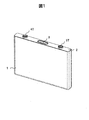
- FIG. 1 is an external perspective view showing a first embodiment of a secondary battery according to the present invention.
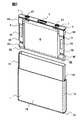
- FIG. 2 is a perspective view showing a wound electrode group in the secondary battery of FIG. 1;
- FIG. 2 is a longitudinal sectional view showing the flow of gas at the time of gas discharge valve breakage in the secondary battery of FIG. 1;
- FIG. 5 is a cross-sectional view taken along the line V-V in FIG.
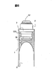
- FIG. 7 is a longitudinal sectional view taken along line VII-VII in FIG. 4;
- FIG. 1 is an external perspective view showing a first embodiment of a secondary battery according to the present invention.
- FIG. 2 is a perspective view showing a wound
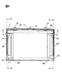
- FIG. 5 is a plan view of FIG. 4;
- the conceptual diagram which shows that the flow-path cross-sectional area of the gas flow path in 1st Embodiment is S1 ⁇ S2 ⁇ S3.
- the longitudinal cross-sectional view which shows the flow of the gas at the time of gas discharge valve cleavage in 2nd Embodiment of the thin lithium ion secondary battery by this invention.
- the thin lithium ion secondary battery has a thin shape having a substantially rectangular parallelepiped appearance.
- the secondary battery has a metal can 1 with a bottom and a flat metal lid 2 whose contour matches the opening of the battery can 1.
- the battery can 1 is made of, for example, a material of aluminum alloy into a thin rectangular parallelepiped having a pair of wide surfaces 1W, a pair of narrow narrow surfaces 1N, and a bottom surface 1B.
- the battery cover 2 is made of an aluminum alloy in this example.
- the outer peripheral contour of the battery lid 2 is joined to the inner peripheral portion of the opening 10 of the battery can 1 by laser (beam) welding, and the opening 10 of the battery can 1 is sealed.
- the battery can 1 and the battery lid 2 constitute a battery outer case.
- a gas discharge valve 3 is provided for releasing the gas outside when the pressure in the battery outer container rises and the pressure is preset.
- the gas discharge valve 3 is a thin film member made of substantially the same metal material as the battery lid 2 and is joined to the battery lid 2 by laser welding or the like.
- a wrapping-like insulating sheet 12 is accommodated, and the wound electrode group 6 is accommodated in the insulating sheet 12.
- the wound electrode group 6 is insulated from the battery case.
- an electrolytic solution and the like are accommodated in the battery outer container.
- the battery can 1 and the battery cover 2 are neutral with no polarity.
- the wound electrode group 6 has a flat wound structure in which a band-shaped separator 6C, a band-shaped negative electrode plate 6E, a band-shaped separator 6C, and a band-shaped positive electrode 6D are sequentially stacked and wound.
- a separator 6C is wound several turns around the winding start end of the wound electrode group 6, and positive and negative electrode plates 6D and 6E are wound on the circumferential surface thereof with the separator 6C interposed.
- the separator 6C is wound several turns, and the outermost periphery (the lowermost surface in FIG. 2) of the separator 6C is adhered by an adhesive tape (not shown) to prevent unwinding. It is stopped.
- the positive electrode plate 6D is manufactured by applying a positive electrode active material mixture on both sides of an aluminum alloy foil.
- a positive electrode active material mixture containing a lithium-containing transition metal double oxide such as lithium manganate is applied (coated) substantially uniformly and substantially uniformly.
- a positive electrode uncoated portion 6A to which the positive electrode active material mixture is not applied is formed on both surfaces at one end in the winding axial direction along the longitudinal direction (rolling direction) of the aluminum alloy foil. That is, in the positive electrode uncoated portion 6A, the aluminum alloy foil (positive electrode current collector) is exposed.
- the negative electrode plate 6E is manufactured by applying a negative electrode active material mixture on both sides of a copper alloy foil.
- a negative electrode active material mixture containing a carbon material such as graphite capable of storing and releasing lithium ions is applied substantially uniformly and substantially uniformly.
- a negative electrode uncoated portion 6B in which the negative electrode active material mixture is not coated is formed on both sides at the other end in the winding axial direction along the longitudinal direction (rolling direction) of the copper alloy foil. That is, in the negative electrode uncoated portion 6B, the copper alloy foil (negative electrode current collector) is exposed.
- the separator 6C is made of a microporous sheet material through which lithium ions can pass.
- a polyethylene sheet several tens of ⁇ m thick is used.
- through holes for connecting the inside and the outside of the battery are formed in the left and right end portions of the battery lid 2, and the positive electrode conductive member 4 and the negative electrode conductive member 5 are formed in the through holes.
- Each is mounted via the insulating sealing material 7.
- the positive electrode conductive member 4 and the negative electrode conductive member 5 exposed to the outside of the battery cover 2 are respectively positive and negative electrode external terminals 4T and 5T, and connect the wound electrode group 6 and an electrical load and a charging power source outside the battery.
- the positive electrode conductive member 4 and the negative electrode conductive member 5 extending into the inside of the battery can are a positive electrode current collector 4S and a negative electrode current collector 5S.
- the positive electrode current collector 4S is bonded to the positive electrode uncoated portion 6A at the flat positive electrode side bonding portion 4A, and the negative electrode current collector 5S is bonded to the negative electrode uncoated portion 6B at the flat negative electrode side bonding portion 5A. It is done.
- the wound electrode group 6 is integrated with the battery cover 2 by the positive and negative electrode conductive members 4 and 5, and is supported by the battery cover 2 in a cantilever state.
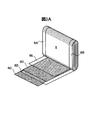
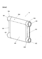
- FIG. 3B is a perspective view of the electrode assembly 6 in which the central regions of the uncoated portions 6A and 6B are compressed.
- a flat portion 6P is formed in the central portion, and a compressed laminated body flat portion 6S is formed in the central region at both ends.
- curved portions 6W are formed along with the winding.
- the curved portion 6W is formed by bending the positive and negative electrode foils at the time of winding, and the positive and negative electrode foils are laminated, but they are not compressed.
- the four corners of the curved portion 6W are referred to as a laminate curved end 6E.
- the flat portion 6P on the front and back faces the pair of wide surfaces 1W of the battery can 1 with a predetermined gap in the battery can 1, and four curved end portions 6E are left and right of the battery can 1. It faces the narrow surface 1N at a predetermined gap. Further, the upper surface of the curved portion 6W is disposed so as to face the inner surface of the battery lid 2 with a predetermined gap, and the lower surface of the curved portion 6W is opposed to the bottom surface 1B of the battery can 1 with a predetermined gap. These four gaps are locations that can be channels for the gas generated inside the electrode group 6. The gas flow path will be described later.
- the region where the wound electrode group 6 is joined to the positive and negative electrode current collectors 4S and 5S at the uncoated portions 6A and 6B is the above-described laminated body compressed flat portion 6S.
- the laminate compression flat portion 6S of the positive and negative electrode foils wound a plurality of times is ultrasonically bonded to the positive and negative electrode current collectors 4S and 5S, and the gaps between the positive and negative electrode foils are also bonded. Therefore, the gas generated by a short circuit, heat generation and the like inside the wound electrode group 6 is hardly discharged outside the electrode group from the laminated body compression flat portion 6S.
- the laminate curved end portion 6E at the four corners of the electrode group 6 functions as a gas discharge portion.
- the gas discharge flow path until the gas generated in the battery can 1 is discharged from the gas discharge valve 3 will be described.
- a minute gap through which gas flows is present between the laminated plurality of foils.
- the broken line arrow A1 indicates the flow of the minute gap in the positive electrode side curved end 6E
- the broken line arrow A2 indicates the minute gap flow in the negative electrode side gas discharge unit 6E. That is, as indicated by dashed arrows A1 and A2 in FIG. 4, the gas generated inside the wound electrode group 6 flows in the winding axial direction of the wound electrode group 6 in the curved portion end 6E.
- the gas discharged from the curved end 6E of the electrode group 6 is a vertical flow path formed by the four curved ends 6E of the electrode group 6 facing the left and right narrow surfaces 1N of the battery can 1 with a predetermined gap.
- This vertical flow passage is referred to as a first gas discharge flow passage FL1.
- the gas having flowed through the first gas discharge flow path FL1 reaches the gas discharge valve 3 via a horizontal flow path formed such that the upper surface of the curved portion 6W faces the inner surface of the battery lid 2 with a predetermined gap.
- This horizontal flow passage is referred to as a second gas discharge flow passage FL2.
- the gases A1 and A2 inside the electrode group 6 reach the space between the both end faces of the electrode group 6 and the battery can narrow surface 1N, and the first gas discharge flow path FL1 is directed vertically to the battery lid 2 Flow. Further, this gas flow flows into the horizontal flow passage which is the second gas discharge flow passage FL2 between the curved portion 6W of the electrode group 6 and the battery cover 2, and flows toward the gas discharge valve 3.
- vertical gases directed to the battery cover 2 on the positive electrode side and the negative electrode side are indicated by broken line arrows B1 and B2.
- horizontal gases directed to the gas discharge valve 3 on the positive electrode side and the negative electrode side are indicated by broken line arrows C1 and C2.
- the horizontal gas indicated by arrows C1 and C2 directed to the gas discharge valve 3 is finally discharged from the cleavage opening of the gas discharge valve 3 to the outside as indicated by the arrow D.
- FIG. 6 is a cross-sectional view of the main part shown by cutting along a VI-VI cutting line of FIG. 4
- FIG. 7 is a cross-sectional view of the main part shown by cutting along a VII-VII cutting line of FIG.
- the positive and negative electrode conductive members 4 and 5 are flow paths in the second gas discharge flow path FL2 through which the horizontal gases C1 and C2 flow. It extends orthogonally and further the sealing material 7 also protrudes, which is a narrow space including many obstacles. Therefore, the minimum flow passage cross-sectional area of the second gas discharge flow passage FL2 is the effective cross-sectional area of the horizontal flow passage.
- the effective cross-sectional area is a value obtained by excluding the area of the obstacle projecting to the horizontal flow path from the cross-sectional area of the flow path divided by the curved portion 6W of the electrode group 6 and the battery cover 2.
- the area of the obstacle is the area of the obstacle orthogonal to the flow path.
- the opening area of the gas discharge valve 3 provided at the center of the battery lid 2 is S3, which is the maximum area of the cleavage opening.
- the cleavage opening does not necessarily open up to the opening area S3, but usually has a value close to or equal to the opening area S3.
- the flow channel cross-sectional areas S1, S2, and S3 are set to satisfy S1 ⁇ S2 ⁇ S3, and the flow channel cross-sectional area is gradually enlarged toward the downstream.
- the gas discharge capacity of the first gas discharge passage FL1 through which the gas indicated by the broken arrows B1 and B2 flows is higher.
- the gas discharge capacity by the opening of the gas discharge valve 3 is higher than that of the second gas discharge flow path FL2 in which the gas indicated by the broken arrows C1 and C2 flows.
- the second gas discharge in which the gas indicated by the broken arrows C1 and C2 flows The gas discharge capacity of the flow path FL2 is lower than the gas discharge capacity of the first gas discharge flow path FL1 through which the gas indicated by the broken arrows B1 and B2 flows. Furthermore, the gas discharge capacity by the opening of the gas discharge valve 3 indicated by the broken line arrow D is lower than the gas discharge capacity of the second gas discharge passage FL2.
- the internal pressure of the battery can not be effectively reduced as follows.
- the maximum gas discharge flow rate in the first gas discharge flow path FL1 of the gas indicated by the broken line arrows B1 and B2 is 10 L / S
- the generated gas amount that is, the flow rate of the gas indicated by the broken line arrows A1 and A2 is 10 L / S
- the pressure of the first gas discharge passage FL1 increases.
- the maximum gas discharge amount of the gas discharge valve 3 is smaller than the maximum gas discharge amount in the second gas discharge passage FL2 indicated by the broken line arrows C1 and C2
- the pressure of the second gas discharge passage FL2 rises Do.
- the internal pressure of the battery outer container may not decrease.
- the cross-sectional areas of those gas flow paths are S1 ⁇ S2 ⁇ S3 and the cross-sectional areas of the gas flow paths are gradually expanded toward the downstream.
- the gas discharge capacity increases toward the downstream side, the gas is discharged very smoothly, and there is no risk that the pressure inside the battery outer container rises after the gas discharge valve 3 is cleaved.
- a thin lithium ion secondary battery having a channel cross-sectional area of S1 ⁇ S2 ⁇ S3 is prepared and used as sample 1 (embodiment), and the channel cross-sectional areas are S1 ⁇ S2 and S3 ⁇ S2.
- a thin lithium ion secondary battery was manufactured and used as Sample 2. Then, a nail having a diameter of 5 mm and a tip angle of 60 ° was penetrated in the center of the battery wide surface to cause a short circuit, and then the internal pressure was measured until the gas generation event ended.
- the battery capacities of the electrode groups 6 used in the samples 1 and 2 are approximately equal.
- the internal pressure increased by a large amount of gas generated by a forced internal short circuit, and the gas discharge valve 3 was cleaved at a preset cleavage pressure.
- the pressure inside the battery case increased to a pressure slightly higher than the cleavage pressure of the gas discharge valve 3.
- thin lithium ion secondary batteries are safe against pressure near the cleavage pressure, but when exposed to repeated heating over a long period, repeated stress, etc., the pressure increase near the cleavage pressure makes the battery outer container durable. There is a fear that sex will decline.
- the pressure is increased by a large amount of gas generated by a forced internal short circuit, the gas discharge valve 3 is cleaved by the cleavage pressure, and thereafter the gas is discharged smoothly. , The pressure rise was suppressed.
- Second Embodiment A second embodiment of a thin lithium ion secondary battery according to the present invention will be described with reference to FIG. In the figure, the same or corresponding portions as in the first embodiment are denoted by the same reference numerals, and the description will be omitted. In the second embodiment, the position of the gas discharge valve in the first embodiment is deviated from the center of the battery cover.
- the gas discharge valve 3 is offset from the center of the battery lid 2. For this reason, in the gas flow path along the battery lid 2, the flow path of the broken arrow C1 and the flow path of the broken arrow C2 are different.
- the influence of the bias of the gas discharge valve 3 on the battery cover 2 on the gas discharge performance was in a negligible range. That is, the second embodiment has the same effect as the first embodiment.
- the above description is one embodiment, and the present invention can be applied to secondary batteries of various structures without departing from the spirit of the present invention.
- the main feature of the present invention is that the cross-sectional area of the gas discharge flow passage until the gas generated inside the electrode group 6 is discharged from the gas discharge valve 3 is set larger toward the downstream. Therefore, the secondary battery having this main feature can be modified, for example, as follows.
- the separator 6C is wound a plurality of times to substitute for the axial core of the electrode group 6.
- the present invention can also be applied to an electrode assembly in which a separator, a negative electrode plate, a separator, and a positive electrode plate are wound on the outer peripheral surface of the shaft core.
- the secondary battery according to the present invention is not limited to the shape and configuration of such a conductive member.
- the present invention can be applied to a secondary battery in which the wide surface 1W of the battery can 1 is sealed with the battery lid 2 and the gas discharge valve 3 is provided on the battery lid 2.
- the cross-sectional area of the first gas discharge passage FL1 is described as being larger than the cross-sectional area of the second gas discharge passage FL2.
- the present invention also includes one in which the cross-sectional area of the first gas discharge passage FL1 and the cross-sectional area of the second gas discharge passage FL2 are substantially equal. Therefore, according to the present invention, the gas generated in the electrode group is discharged from the gas discharge valve, and the opening area at the time of cleavage of the gas discharge valve is set larger than the cross-sectional area of the gas discharge passage from the electrode group to the gas discharge valve Can be applied to any secondary battery.
- the present invention can be applied to various secondary batteries having a wound electrode group, such as a nickel-hydrogen secondary battery, other than the lithium ion secondary battery.
- the present invention can be applied to various lithium ion capacitors having a wound electrode group.
Landscapes
- Chemical & Material Sciences (AREA)
- Chemical Kinetics & Catalysis (AREA)
- Electrochemistry (AREA)
- General Chemical & Material Sciences (AREA)
- Engineering & Computer Science (AREA)
- Manufacturing & Machinery (AREA)
- Materials Engineering (AREA)
- Gas Exhaust Devices For Batteries (AREA)
- Secondary Cells (AREA)
- Sealing Battery Cases Or Jackets (AREA)
- Connection Of Batteries Or Terminals (AREA)
Abstract
Description
本発明の第2の態様による二次電池は、第1の態様による二次電池において、前記ガス排出弁の開裂時の開口面積が、前記電極群からガス排出弁まで至るガス排出流路の断面積よりも大きく設定したものである。
本発明の第3の態様による二次電池は、第1または2の態様による二次電池において、前記ガス排出流路は、前記電池外装容器と電極群との間に形成され、前記電極群から排出されるガスが前記ガス排出弁まで到達する際に垂直方向に流れる第1ガス排出流路と、前記第1ガス排出流路から流れ込んだガスが水平方向に流れる第2ガス排出流路とを有し、前記第1ガス排出流路の断面積をS1、前記第2ガス排出流路の断面積をS2、ガス排出弁の開口の断面積をS3とするとき、S1<S2<S3に設定したものである。
本発明の第4の態様による二次電池は、第3の態様による二次電池において、前記電極群は、前記セパレータを介在させて正負極板を捲回して構成され、表裏一対の平面部と前記平面部を連続する湾曲部とを有する薄型形状であり、前記集電部は圧縮された積層体とされ、前記電極群内部で発生したガスは前記湾曲部の端面から排出されるものである。
本発明の第5の態様による二次電池は、第1または2の態様による二次電池において、前記電極群は、前記セパレータを介在させて正負極板を捲回して構成され、表裏一対の平面部と前記平面部を連続する湾曲部とを有する薄型形状であり、前記集電部は圧縮された積層体とされ、前記電極群内部で発生したガスは前記湾曲部の端面から排出されるものである。
本発明の第6の態様による二次電池は、第5の態様による二次電池において、前記外装容器は、表裏一対の幅広面と左右一対の幅狭面と底面で形成される薄型直方体形状の電池缶と、前記底面と対向する電池缶の開口を覆って当該開口を封口し、前記ガス排出弁を有する電池蓋とを有し、前記薄型形状の電極群の前記平面部は前記幅広面と対向し、前記電極群の両端面は前記幅狭面と対向し、前記電極群の湾曲部は前記電池蓋と対向し、前記第1ガス排出流路は、前記電極群の両端面と前記幅狭面とが対向する空間に形成された垂直流路であり、前記第2ガス排出流路は、前記電極群の湾曲部と前記電池蓋とが対向する空間に形成された水平流路である。
本発明の第7の態様による二次電池は、第6の態様による二次電池において、前記第1ガス排出流路の断面積をS1、前記第2ガス排出流路の断面積をS2、ガス排出弁の開口断面積をS3とするとき、S1<S2<S3に設定したものである。
図1および図2に示すように、薄型リチウムイオン二次電池は、外観が略直方体の薄型形状を呈している。この二次電池は、有底の金属製の電池缶1と、電池缶1の開口部に輪郭が合致する平板状の金属製の電池蓋2とを有している。電池缶1は、例えばアルミニウム合金の素材から、一対の幅広面1Wと、一対の細長い幅狭面1Nと、底面1Bとを有する薄型直方体に作製される。
なお、本実施形態の二次電池は、電池缶1および電池蓋2が極性を持たない中性である。
捲回型電極群6は、正負極導電部材4、5により電池蓋2と一体化され、電池蓋2に片持ち状態で支持されている。
湾曲部端部6Eには、積層された複数枚の箔同士の間にガスが流れる微小な隙間が存在する。破線矢印A1は正極側湾曲端部6E内の微小隙間の流れを、破線矢印A2は負極側ガス排出部6E内の微小隙間流れを示す。すなわち、図4に破線矢印A1,A2で示すように、捲回型電極群6の内部で発生したガスは、湾曲部端部6E内で捲回型電極群6の捲回軸方向に流れる。
第1ガス排出流路FL1を流れたガスは、湾曲部6Wの上面が電池蓋2の内面と所定の間隙で対向して形成される水平流路を経由してガス排出弁3に至る。この水平流路を第2ガス排出流路FL2と呼ぶ。
S1=S1A+S1B 式(1)
と表される。
S2=S2A+S2B 式(2)
と表される。
例えば、破線矢印B1,B2で示されるガスの第1ガス排出流路FL1における最大ガス排出流量が10L/S、発生ガス量、すなわち、破線矢印A1、A2で示されるガスの流量が10L/Sであったとき、第2ガス排出流路FL2における最大ガス排出流量は10L/Sよりも少ないので、第1ガス排出流路FL1の圧力が上昇する。
同様に、ガス排出弁3の最大ガス排出量は、破線矢印C1,C2で示される第2ガス排出流路FL2における最大ガス排出量よりも少ないので、第2ガス排出流路FL2の圧力が上昇する。
ガス排出流路面積を変化させたリチウムイオン電池を製造し、異常な動作を想定した強制内部短絡試験を行い、本発明の効果を確認した。
一般に薄型リチウムイオン二次電池は開裂圧力近くの圧力に対しては安全であるが、長期間の繰り返し過熱、繰り返し応力等に曝された場合、開裂圧力近傍の圧力上昇により、電池外装容器の耐久性が低下する惧れがある。
本発明による薄型リチウムイオン二次電池の第2実施形態を、図12を参照して説明する。なお、図中、第1実施形態と同一もしくは相当部分には同一符号を付し、説明を省略する。第2実施形態は、第1実施形態におけるガス排出弁の位置を電池蓋の中央から偏倚させたものである。
以上の説明は一実施形態であり、本発明の趣旨に逸脱しない種々の構造の二次電池に本発明を適用することができる。本発明の主たる特徴は、電極群6の内部で発生したガスがガス排出弁3から排出されるまでのガス排出流路について、下流ほど断面積を大きく設定した点である。したがって、この主たる特徴を有する二次電池は、たとえば、以下のように変形して実施することができる。
Claims (7)
- ガス排出弁と正負極外部端子が設けられた電池外装容器と、
セパレータを介在させて正負極板を積層し、両端に集電部を設けた電極群と、
前記電極群の前記集電部から前記正負極外部端子に至る電流経路を構成する正負極集電体とを備え、
前記電極群の内部で発生したガスが前記ガス排出弁から排出されるガス排出流路は、下流に向かうほど断面積が大きく設定されている二次電池。 - 請求項1に記載の二次電池において、
前記ガス排出弁の開裂時の開口面積が、前記電極群からガス排出弁まで至るガス排出流路の断面積よりも大きく設定した二次電池。 - 請求項1または2に記載の二次電池において、
前記ガス排出流路は、前記電池外装容器と電極群との間に形成され、前記電極群から排出されるガス流が前記ガス排出弁まで到達する際に垂直方向に流れる第1ガス排出流路と、前記第1ガス排出流路から流れ込んだガスが水平方向に流れる第2ガス排出流路とを有し、
前記第1ガス排出流路の断面積をS1、前記第2ガス排出流路の断面積をS2、ガス排出弁の開口の断面積をS3とするとき、S1<S2<S3に設定した二次電池。 - 請求項3に記載の二次電池において、
前記電極群は、前記セパレータを介在させて正負極板を捲回して構成され、表裏一対の平面部と前記平面部を連続する湾曲部とを有する薄型形状であり、
前記集電部は圧縮された積層体とされ、前記電極群内部で発生したガスは前記湾曲部の端面から排出される二次電池。 - 請求項1または2に記載の二次電池において、
前記電極群は、前記セパレータを介在させて正負極板を捲回して構成され、表裏一対の平面部と前記平面部を連続する湾曲部とを有する薄型形状であり、
前記集電部は圧縮された積層体とされ、前記電極群内部で発生したガスは前記湾曲部の端面から排出される二次電池。 - 請求項5に記載の二次電池において、
前記外装容器は、
表裏一対の幅広面と左右一対の幅狭面と底面で形成される薄型直方体形状の電池缶と、前記底面と対向する電池缶の開口を覆って当該開口を封口し、前記ガス排出弁を有する電池蓋とを有し、
前記薄型形状の電極群の前記平面部は前記幅広面と対向し、前記電極群の両端面は前記幅狭面と対向し、前記電極群の湾曲部は前記電池蓋と対向し、
前記第1ガス排出流路は、前記電極群の両端面と前記幅狭面とが対向する空間に形成された垂直流路であり、
前記第2ガス排出流路は、前記電極群の湾曲部と前記電池蓋とが対向する空間に形成された水平流路である二次電池。 - 請求項6に記載の二次電池において、
前記第1ガス排出流路の断面積をS1、前記第2ガス排出流路の断面積をS2、ガス排出弁の開口の断面積をS3とするとき、S1<S2<S3に設定した二次電池。
Priority Applications (5)
| Application Number | Priority Date | Filing Date | Title |
|---|---|---|---|
| US14/112,146 US9391308B2 (en) | 2011-04-18 | 2011-04-18 | Secondary battery |
| CN201180070265.3A CN103493248B (zh) | 2011-04-18 | 2011-04-18 | 二次电池 |
| JP2013510751A JP5770836B2 (ja) | 2011-04-18 | 2011-04-18 | 二次電池 |
| PCT/JP2011/059536 WO2012143995A1 (ja) | 2011-04-18 | 2011-04-18 | 二次電池 |
| US15/177,771 US9843028B2 (en) | 2011-04-18 | 2016-06-09 | Secondary battery |
Applications Claiming Priority (1)
| Application Number | Priority Date | Filing Date | Title |
|---|---|---|---|
| PCT/JP2011/059536 WO2012143995A1 (ja) | 2011-04-18 | 2011-04-18 | 二次電池 |
Related Child Applications (2)
| Application Number | Title | Priority Date | Filing Date |
|---|---|---|---|
| US14/112,146 A-371-Of-International US9391308B2 (en) | 2011-04-18 | 2011-04-18 | Secondary battery |
| US15/177,771 Continuation US9843028B2 (en) | 2011-04-18 | 2016-06-09 | Secondary battery |
Publications (1)
| Publication Number | Publication Date |
|---|---|
| WO2012143995A1 true WO2012143995A1 (ja) | 2012-10-26 |
Family
ID=47041148
Family Applications (1)
| Application Number | Title | Priority Date | Filing Date |
|---|---|---|---|
| PCT/JP2011/059536 Ceased WO2012143995A1 (ja) | 2011-04-18 | 2011-04-18 | 二次電池 |
Country Status (4)
| Country | Link |
|---|---|
| US (2) | US9391308B2 (ja) |
| JP (1) | JP5770836B2 (ja) |
| CN (1) | CN103493248B (ja) |
| WO (1) | WO2012143995A1 (ja) |
Cited By (3)
| Publication number | Priority date | Publication date | Assignee | Title |
|---|---|---|---|---|
| JP2016115408A (ja) * | 2014-12-11 | 2016-06-23 | 株式会社Gsユアサ | 蓄電素子 |
| WO2017126689A1 (ja) | 2016-01-22 | 2017-07-27 | 旭化成株式会社 | 非水系リチウム蓄電素子 |
| JP2025505067A (ja) * | 2022-07-15 | 2025-02-20 | 香港時代新能源科技有限公司 | 電池と電力消費装置 |
Families Citing this family (4)
| Publication number | Priority date | Publication date | Assignee | Title |
|---|---|---|---|---|
| KR102299244B1 (ko) * | 2015-01-14 | 2021-09-07 | 삼성에스디아이 주식회사 | 이차 전지 및 그 팩 |
| JP7266567B2 (ja) * | 2020-11-09 | 2023-04-28 | プライムプラネットエナジー&ソリューションズ株式会社 | 角型電池 |
| CN116706416B (zh) * | 2023-08-07 | 2023-10-13 | 蜂巢能源科技股份有限公司 | 一种动力电池及电池包 |
| CN119674419B (zh) * | 2024-12-24 | 2025-09-09 | 蜂巢能源科技股份有限公司 | 电芯及电池包 |
Citations (4)
| Publication number | Priority date | Publication date | Assignee | Title |
|---|---|---|---|---|
| JPH10162801A (ja) * | 1996-11-29 | 1998-06-19 | Nissan Motor Co Ltd | 二次電池 |
| JP2006244756A (ja) * | 2005-03-01 | 2006-09-14 | Nec Lamilion Energy Ltd | フィルム外装電気デバイス及びフィルム外装電気デバイス集合体 |
| JP2007220418A (ja) * | 2006-02-15 | 2007-08-30 | Denso Corp | 電池 |
| JP2009289741A (ja) * | 2008-05-30 | 2009-12-10 | Samsung Sdi Co Ltd | キャップ組立体及びそれを用いた二次電池 |
Family Cites Families (5)
| Publication number | Priority date | Publication date | Assignee | Title |
|---|---|---|---|---|
| JP4397175B2 (ja) * | 2003-04-11 | 2010-01-13 | トヨタ自動車株式会社 | 蓄電素子 |
| JP5456967B2 (ja) * | 2007-12-06 | 2014-04-02 | 冨士発條株式会社 | アルミ角形2次電池ケース |
| JP5225805B2 (ja) * | 2008-10-27 | 2013-07-03 | 日立ビークルエナジー株式会社 | 二次電池およびその製造方法 |
| JP5277871B2 (ja) | 2008-11-04 | 2013-08-28 | トヨタ自動車株式会社 | 電池 |
| JP5507173B2 (ja) | 2009-09-25 | 2014-05-28 | パナソニック株式会社 | 電池モジュールとそれを用いた電池パック |
-
2011
- 2011-04-18 WO PCT/JP2011/059536 patent/WO2012143995A1/ja not_active Ceased
- 2011-04-18 US US14/112,146 patent/US9391308B2/en not_active Expired - Fee Related
- 2011-04-18 CN CN201180070265.3A patent/CN103493248B/zh not_active Expired - Fee Related
- 2011-04-18 JP JP2013510751A patent/JP5770836B2/ja not_active Expired - Fee Related
-
2016
- 2016-06-09 US US15/177,771 patent/US9843028B2/en not_active Expired - Fee Related
Patent Citations (4)
| Publication number | Priority date | Publication date | Assignee | Title |
|---|---|---|---|---|
| JPH10162801A (ja) * | 1996-11-29 | 1998-06-19 | Nissan Motor Co Ltd | 二次電池 |
| JP2006244756A (ja) * | 2005-03-01 | 2006-09-14 | Nec Lamilion Energy Ltd | フィルム外装電気デバイス及びフィルム外装電気デバイス集合体 |
| JP2007220418A (ja) * | 2006-02-15 | 2007-08-30 | Denso Corp | 電池 |
| JP2009289741A (ja) * | 2008-05-30 | 2009-12-10 | Samsung Sdi Co Ltd | キャップ組立体及びそれを用いた二次電池 |
Cited By (6)
| Publication number | Priority date | Publication date | Assignee | Title |
|---|---|---|---|---|
| JP2016115408A (ja) * | 2014-12-11 | 2016-06-23 | 株式会社Gsユアサ | 蓄電素子 |
| WO2017126689A1 (ja) | 2016-01-22 | 2017-07-27 | 旭化成株式会社 | 非水系リチウム蓄電素子 |
| KR20180084150A (ko) | 2016-01-22 | 2018-07-24 | 아사히 가세이 가부시키가이샤 | 비수계 리튬 축전 소자 |
| US10886533B2 (en) | 2016-01-22 | 2021-01-05 | Asahi Kasei Kabushiki Kaisha | Nonaqueous lithium power storage element |
| JP2025505067A (ja) * | 2022-07-15 | 2025-02-20 | 香港時代新能源科技有限公司 | 電池と電力消費装置 |
| JP7843358B2 (ja) | 2022-07-15 | 2026-04-09 | 香港時代新能源科技有限公司 | 電池と電力消費装置 |
Also Published As
| Publication number | Publication date |
|---|---|
| US9391308B2 (en) | 2016-07-12 |
| JP5770836B2 (ja) | 2015-08-26 |
| JPWO2012143995A1 (ja) | 2014-07-28 |
| US20160293919A1 (en) | 2016-10-06 |
| US9843028B2 (en) | 2017-12-12 |
| CN103493248B (zh) | 2016-03-09 |
| CN103493248A (zh) | 2014-01-01 |
| US20140038003A1 (en) | 2014-02-06 |
Similar Documents
| Publication | Publication Date | Title |
|---|---|---|
| JP7484992B2 (ja) | 蓄電素子 | |
| JP5803713B2 (ja) | 蓄電装置及び車両 | |
| CN106025373B9 (zh) | 方形二次电池以及使用其的组电池 | |
| JP2025094239A (ja) | 二次電池及びその製造方法 | |
| US10141560B2 (en) | Energy storage device including a pressing member pressing a separator toward an electrode assembly | |
| US9843028B2 (en) | Secondary battery | |
| JP6891930B2 (ja) | 角形二次電池及びそれを用いた組電池 | |
| US20170125848A1 (en) | Method for manufacturing prismatic secondary battery | |
| KR20170049014A (ko) | 테이핑을 이용하는 벤팅 구조의 전지셀 | |
| JP7304330B2 (ja) | 二次電池 | |
| KR20110105737A (ko) | 파우치형 케이스 및 이를 포함하는 전지팩 | |
| US12322760B2 (en) | Secondary battery | |
| JP2011181215A (ja) | 角形電池およびその製造方法 | |
| US20220069359A1 (en) | Rectangular secondary battery | |
| WO2021060009A1 (ja) | 二次電池及びその製造方法 | |
| JP2021120961A (ja) | 角形二次電池及びそれを用いた組電池 | |
| KR101821488B1 (ko) | 전지 | |
| JP6047632B2 (ja) | 二次電池 | |
| WO2018235768A1 (ja) | 蓄電素子 | |
| JP6089832B2 (ja) | 蓄電素子 | |
| JP6246540B2 (ja) | 非水電解質二次電池 | |
| JP7522718B2 (ja) | 二次電池 | |
| CN105591041A (zh) | 二次电池 | |
| JP2018116867A (ja) | 蓄電素子、及び蓄電素子の製造方法 | |
| JP7495917B2 (ja) | 二次電池 |
Legal Events
| Date | Code | Title | Description |
|---|---|---|---|
| WWE | Wipo information: entry into national phase |
Ref document number: 201180070265.3 Country of ref document: CN |
|
| 121 | Ep: the epo has been informed by wipo that ep was designated in this application |
Ref document number: 11864081 Country of ref document: EP Kind code of ref document: A1 |
|
| ENP | Entry into the national phase |
Ref document number: 2013510751 Country of ref document: JP Kind code of ref document: A |
|
| WWE | Wipo information: entry into national phase |
Ref document number: 14112146 Country of ref document: US |
|
| NENP | Non-entry into the national phase |
Ref country code: DE |
|
| 122 | Ep: pct application non-entry in european phase |
Ref document number: 11864081 Country of ref document: EP Kind code of ref document: A1 |