WO2012141259A1 - 充電装置 - Google Patents
充電装置 Download PDFInfo
- Publication number
- WO2012141259A1 WO2012141259A1 PCT/JP2012/060059 JP2012060059W WO2012141259A1 WO 2012141259 A1 WO2012141259 A1 WO 2012141259A1 JP 2012060059 W JP2012060059 W JP 2012060059W WO 2012141259 A1 WO2012141259 A1 WO 2012141259A1
- Authority
- WO
- WIPO (PCT)
- Prior art keywords
- lever member
- contact
- electronic device
- spring
- charging device
- Prior art date
- Legal status (The legal status is an assumption and is not a legal conclusion. Google has not performed a legal analysis and makes no representation as to the accuracy of the status listed.)
- Ceased
Links
Images





Classifications
-
- H—ELECTRICITY
- H02—GENERATION; CONVERSION OR DISTRIBUTION OF ELECTRIC POWER
- H02J—ELECTRIC POWER NETWORKS; CIRCUIT ARRANGEMENTS OR SYSTEMS FOR SUPPLYING OR DISTRIBUTING ELECTRIC POWER; SYSTEMS FOR STORING ELECTRIC ENERGY
- H02J7/00—Circuit arrangements for charging or discharging batteries or for supplying loads from batteries
- H02J7/70—Circuit arrangements for charging or discharging batteries or for supplying loads from batteries characterised by the mechanical construction
- H02J7/731—Circuit arrangements for charging or discharging batteries or for supplying loads from batteries characterised by the mechanical construction specially adapted for holding portable devices containing batteries
Definitions
- the present invention relates to a charging device, and more particularly, to a charging device configured to be connected to an electrode of an electronic device by displacing a contact when the electronic device is mounted.
- an electronic device represented by a portable terminal device has a built-in rechargeable battery, and the rechargeable battery is used as a power source by charging the rechargeable battery.
- a charging device (Credor) is used. Then, the electronic device is mounted on a mounting base of the charging device, and the charging contact of the charging device is connected to the charging electrode provided in the electronic device, thereby charging.
- the contacts In the state where the charging contact provided in the charging device is exposed from the mounting base, when the contact is deformed by an external force or the like, the contacts (normally two contacts are provided) are short-circuited or electronic The device cannot be properly connected to the electrode.
- the charging device is provided with a contact moving mechanism that protrudes the contact from the mounting base only when the electronic device is mounted on the charging device.
- this contact moving mechanism is configured to be rotatable around a support shaft, and a projection is formed that engages with an electronic device attached to one end, and a contact is provided at the other end. It has a lever member.
- the lever member is biased by a spring member in a direction in which the protrusion protrudes from the mounting base.
- the protrusion protrudes from the mounting base hereinafter referred to as an unmounted state
- the lever member is The provided contact is hidden inside the mounting base.
- the spring member that moves and urges the lever member together with the contact.
- the spring member is disposed on the rotation support shaft of the lever member, and the contact is disposed on the end of the lever member.
- the spring member needs to be a torsion spring, and there is a problem that sag is likely to occur due to the rotation operation of the lever member over time.
- the contact does not protrude from the mounting base even when the electronic device is mounted, or the contact remains protruding from the mounting base, and the movement stability of the contact decreases. . Therefore, the contact and the electrode of the electronic device may not be properly connected, and the reliability of the charging device is reduced.
- the present invention generally aims to provide an improved and useful charging device that solves the above-described problems of the prior art.
- a more detailed object of the present invention is to provide a charging device with improved stability of contact movement when an electronic device is mounted.
- the present invention provides: A mounting base (20) on which the electronic device (1) is mounted; A lever member (40) that moves from the unmounted position to the mounted position by mounting the electronic device (1) on the mounting table (20); A spring member (62) for urging and moving the lever member (40) from the mounted position toward the unmounted position; Provided on the lever member (40), when the lever member (40) moves to the mounting position, it protrudes from the wall (22a) of the mounting base (20) and is an electrode of the electronic device (1).
- a compression spring as a spring member, it is possible to suppress the occurrence of spring sag and to reduce the size of the charging device because the spring member and the contact point are disposed close to each other.
- the cross-sectional perspective view which expands and shows the non-wearing state of the charging device which is one Embodiment of this invention. It is a cross-sectional perspective view which expands and shows the mounting state of the charging device which is one Embodiment of this invention.
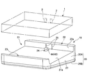
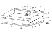
- FIG. 1, FIG. 2A, and FIG. 2B are diagrams for explaining the overall configuration of a charging device 10 that is an embodiment of the present invention.
- FIG. 1 is an exploded perspective view of the charging device 10
- FIGS. 2A and 2B are perspective views showing the appearance of the charging device 10.
- the electronic device 1 is attached to the charging device 10, and the electronic device 1 is charged in this attached state.
- the electronic device 1 is provided with a charging electrode 2 (see FIGS. 2A and 2B), and the contact 61 of the charging device 10 is connected to the electrode 2, whereby the electronic device 1 is connected to the electronic device 1. And charging.
- the details of the charging apparatus 10 will be described.
- the charging device 10 has a mounting base 20 and a contact moving mechanism 30.
- the mounting base 20 includes an upper half 20A and a lower half 20B, and the mounting base 20 is configured by combining and fixing the half halves 20A and 20B.
- the mounting table 20 is made of, for example, hard resin.
- the upper half 20A is provided with a mounting recess 21 in which the electronic device 1 is mounted. Further, standing portions 22 and 23 are formed in the upper half body 20A so as to sandwich the mounting recess 21. When the electronic device 1 is mounted in the mounting recess 21, the electronic device 1 is sandwiched between the pair of standing portions 22 and 23. Moreover, in order to improve the mounting property with respect to the mounting base 20 of the electronic device 1, the bottom surface 21a of the mounting recess 21 is an inclined surface having a predetermined angle.
- an opening 24 is formed at a predetermined position on the bottom surface 21a.
- a projection 44 of a lever member 40 described later is disposed in the opening 24.
- the wall portion 22a of the standing portion 22, a pair of contact windows 25 are formed.
- a contact 61 to be described later protrudes from the contact window 25 into the mounting recess 21 and is connected to the electrode 2 of the electronic device 1 (details will be described later).
- a bearing portion (not shown in the figure) for bearing a support shaft portion 43 of a lever member 40 described later is formed on the inner wall of the side wall 27 of the upper half body 20A.
- the lower half 20B has a boss 26 formed therein.
- a substrate 80 is fixed to the boss 26 by screws (not shown).
- the substrate 80, the lead portion 63 of the spring unit 60 which constitutes the contact moving mechanism 30 to be described later is connected.
- the contact moving mechanism 30 is disposed inside the mounting table 20 described above.
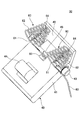
- the contact moving mechanism 30 has a lever member 40 and a spring unit 60 as shown in an enlarged view in FIG.
- the lever member 40 is a resin molded product and has a structure in which a lever main body 41, a unit mounting portion 42, a support shaft portion 43, and the like are integrally formed. Further, the lever main body 41 and the unit mounting portion 42 form a predetermined angle with the support shaft portion 43 as the center, and thus the lever member 40 has a substantially L shape in a side view.
- a protrusion 44 is formed on the lever body 41. Also, the unit mounting portion 42 mounting hole 45 for mounting the spring unit 60 is formed. Further, the support shaft portion 43 formed at the boundary portion between the lever main body 41 and the unit mounting portion 42 is supported by a bearing portion formed inside the side wall portion 27. Thereby, the lever member 40 becomes a structure which can rotate centering on the spindle part 43. As shown in FIG.
- the spring unit 60 is made of a metal wire having electrical conductivity and spring property, and as shown in an enlarged view in FIG. 4, a contact 61, a conical coil spring 62, a lead portion 63, and the like are integrally formed. .
- the contact 61 is connected to the electrode 2 of the electronic device 1 when the electronic device 1 is mounted on the mounting base 20.
- the contact 61 has a terminal structure by forming an extension 61a extending linearly from a connection 64 connected to a conical coil spring 62, which will be described later, and a bent end portion of the extension 61a. It is comprised by the contact part 61b.
- the contact 61 can be inserted into and removed from the contact window 25 formed in the wall portion 22a of the upper half 20A.
- Conical coil spring 62 has a structure formed by winding the metal wire conically.
- the conical coil spring 62 is set such that the diameter of the conical coil spring 62 on the side facing the wall portion 22a is larger than the diameter of the lever member 40 on the side where the unit mounting portion 42 is mounted.
- the end portion on the small diameter side of the conical coil spring 62 is connected to the contact point 61 (extending portion 61 a) described above at the connection portion 64.
- the end portion of the large diameter side of the conical coil spring 62, the lead portion 63 is provided.
- the lead portion 63 is extended downward, are connected to the substrate 80 (soldering).
- the contact 61 is configured to be electrically connected to the substrate 80 via the conical coil spring 62 and the lead portion 63.
- the conical coil spring 62 constitutes a compression spring in the present embodiment. Further, the contact 61 described above is configured to be located at the center position (axial position) in the conical coil spring 62 having a conical shape.
- the connecting portion 64 is mounted (fitted) in the mounting hole 45 of the unit mounting portion 42.
- the spring unit 60 with respect to the lever member 40 is two arranged. In a state where the pair of spring units 60 are disposed on the lever member 40, the lead portion 63 of one spring unit 60 is connected to the substrate 80 through the insertion hole 46 formed in the lever body 41, and the other The lead part 63 of the spring unit 60 passes through the outer part of the lever body 41 and is connected to the substrate 80 (see FIG. 3).
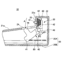
- FIG. 5A and FIG. 6A shows a state of mounting the contact moving mechanism 30 to the mounting stand 20.
- the conical coil spring 62 is disposed between the wall portion 22 a and the unit mounting portion 42 with the mounting base 20 mounted on the contact moving mechanism 30. Therefore, the conical coil spring 62 is disposed so as to face the wall portion 22a.
- the conical coil spring 62 urges the elastic force to rotate the lever member 40 about the support shaft portion 43 in the clockwise direction (arrow B2 direction) in FIGS. 5A and 5B.
- the lever main body 41 abuts against the back surface of the bottom surface 21a, further rotation of the lever member 40 is restricted.
- the protruding portion 44 formed on the lever member 40 is configured to protrude from the opening 24 to the upper portion of the bottom surface 21a.
- the unit mounting portion 42 is also displaced in the direction of the arrow B2, so that the wall portion 22a and the unit mounting portion 42 are largely separated. Therefore, the conical coil spring 62 disposed between the wall portion 22a and the unit mounting portion 42 is in an extended state.
- the length of the contact 61 be L1
- the length of the conical coil spring 62 be L2
- the thickness L3 of the wall 22a see FIG. 5A.
- the length L1 of the contact 61, the length L2 of the conical coil spring 62, and the thickness L3 of the wall portion 22a when the lever member 40 is not mounted are set to satisfy L2 ⁇ L1 ⁇ (L2 + L3). is doing.
- the contact 61 protrudes from the end portion on the large diameter side of the conical coil spring 62 in the unmounted state. Therefore, in the unmounted state, the contact 61 of the spring unit 60 is in a state where a part of the contact 61 enters the contact window 25 formed in the wall portion 22a.
- the length L1 of the contact 61 is smaller than the length (L2 + L3) obtained by adding the length L2 of the conical coil spring 62 and the thickness L3 of the wall portion 22a, the contact 61 is removed from the contact window 25 in the unmounted state. is not such as to protrude into the mounting recess 21 (FIGS. 2A, 5A, see Fig. 6A).
- the electronic device 1 is mounted from the top to the mounting base 20 of the charging device 10.
- a state in which the electronic device 1 is mounted on the charging device 10 is referred to as a mounted state.
- the electronic device 1 In the mounted state, as shown in FIG. 2B, the electronic device 1 is positioned in the mounting recess 21 of the mounting base 20 and is configured to be sandwiched between the pair of standing portions 22 and 23. Further, when the electronic device 1 is mounted in the mounting recess 21, the protrusion 44 of the lever member 40 protruding from the bottom surface 21 a is pressed downward. As a result, the lever member 40 is urged to rotate counterclockwise (arrow B1 direction) in FIGS. 5A and 5B, so that the lever member 40 rotates in the B1 direction against the elastic force of the conical coil spring 62.
- FIG. 2B, FIG. 5B, and FIG. 6B show a state in which the lever member 40 has been rotated to a position where it is pressed by the electronic device 1 to which the protruding portion 44 is attached and is substantially at the same height as the bottom surface 21a.
- the position of the lever member 40 in this mounting state is referred to as a mounting position.
- the unit mounting portion 42 When the lever member 40 moves from the unmounted position to the mounted position, the unit mounting portion 42 also rotates and moves in the B1 direction. As a result, the unit mounting portion 42 presses the end portion on the small diameter side of the conical coil spring 62 toward the wall portion 22a. Therefore, the conical coil spring 62 contracts while accumulating elastic force.
- the contact 61 is configured to extend in a substantially perpendicular direction from the unit mounting portion 42. For this reason, when the unit mounting portion 42 moves in the B1 direction, the tip of the contact 61 protrudes from the contact window 25 into the mounting recess 21.
- the formation position of the contact window 25 is set so as to correspond to the formation position of the electrode 2 of the electronic device 1 mounted on the mounting base 20.
- the contact 61 protrudes from the contact window 25, the contact 61 is pressed and electrically connected to the electrode 2 of the electronic device 1. At this time, since a part of the tip of the contact 61 is inserted into the contact window 25 in the non-mounted state as described above, the contact 61 becomes a wall when the lever member 40 moves from the non-mounted position to the mounted position. It can protrude smoothly from the contact window 25 without colliding with the part 22a.
- the conical coil spring 62 biases the lever member 40 from the mounting position toward the non-mounting position. Rotation toward the unmounted position (rotation in the direction of arrow B2) is started. Then, when the lever main body 41 comes into contact with the bottom surface 21a again, the movement of the lever member 40 is restricted, and the charging device 10 is in a state before being mounted.
- the charging device 10 uses the elastic force accumulated in the conical coil spring 62 as a driving force for returning the lever member 40 from the attachment position to the non-attachment position.
- a torsion spring is used separately from the contact point as a spring for returning the lever member from the mounted position to the unmounted position, and this torsion spring is disposed on the support shaft portion of the lever member.
- this torsion spring is used separately from the contact point as a spring for returning the lever member from the mounted position to the unmounted position, and this torsion spring is disposed on the support shaft portion of the lever member.
- the charging device 10 since the charging device 10 according to the present embodiment uses the spring unit 60 in which the contact 61 and the conical coil spring 62 are integrated, the number of parts can be reduced and the charging device 10 can be downsized. Can do.
- the expansion / contraction load in the axial direction of the spring wire constituting the torsion spring is large.
- a large diameter causes "sagging".
- the conical coil spring 62 is used as in the present embodiment, the load is applied in the direction perpendicular to the spring axis, and the expansion / contraction load is not applied in the axial direction of the spring wire. Therefore, it is possible to prevent the by using the conical coil spring 62, "sag" is generated.
- the torsion spring needs to be disposed on the support shaft portion to which the most stress of the lever member is applied. Therefore, in order to reliably return the lever member from the mounting position to the non-mounting position, it is necessary to use a thick wire with high rigidity.
- the conical coil spring 62 is not disposed at the support shaft portion 43 but at the arrangement position of the contact 61 (that is, the position away from the support shaft portion 43 of the unit mounting portion 42). Therefore, even if a relatively thin wire (for example, a ⁇ 0.15 mm piano wire) is used as the wire over the spring unit 60 in order to ensure the rotation of the lever member 40, the conical coil spring 62 can be used. It is possible to prevent “sagging” from occurring.
- a relatively thin wire for example, a ⁇ 0.15 mm piano wire
Landscapes
- Engineering & Computer Science (AREA)
- Power Engineering (AREA)
- Charge And Discharge Circuits For Batteries Or The Like (AREA)
- Secondary Cells (AREA)
Abstract
本発明は電子機器が装着されることにより接点が変位して電子機器の電極に接続する構成とされた充電装置に係り、電子機器が装着される装着台と、前記電子機器が前記装着台に装着されることにより、未装着位置から装着位置に移動するレバー部材と、前記レバー部材を前記装着位置から未装着位置に向け移動付勢するばね部材と、前記レバー部材に設けられており、前記レバー部材が前記装着位置に移動した際、前記装着台の壁部から突出して前記電子機器の電極に接続される接点とを有する充電装置であって、前記ばね部材として圧縮ばねを用いると共に、前記ばね部材を前記レバー部材の前記接点の配設位置に前記壁部と対向するよう配設する。
Description
本発明は充電装置に係り、特に電子機器が装着されることにより接点が変位して電子機器の電極に接続する構成とされた充電装置に関する。
近年、携帯端末装置に代表されるような電子機器は充電池を内蔵しており、この充電池に充電を行うことによりこれを電源とするものが多用されている。この種の電子機器に対して充電を行う場合、充電装置(クレドール)が用いられる。そして、電子機器を充電装置の装着台に装着し、充電装置の充電用の接点を電子機器に設けられた充電用の電極に接続し、これにより充電を行う構成とされている。
また、充電装置に設けられる充電用の接点が装着台から露出した状態では、接点が外力等により変形した場合、接点同士(通常、接点は2個設けられている)が短絡したり、また電子機器の電極に適正に接続することができなくなる。
このため充電装置では、電子機器が充電装置に装着された時にのみ接点を装着台から突出させる接点移動機構が設けられている。従来、この接点移動機構は支軸を中心として回転可能な構成とされており、一端部に装着される電子機器と係合する突起部が形成されると共に他端部に接点が配設されたレバー部材を有している。このレバー部材は、ばね部材により突起部が装着台から突出する方向に付勢されており、突起部が装着台から突出した状態(以下、未装着状態という)では、レバー部材の他端部に設けられた接点は、装着台の内側に隠れた状態となっている。
この未装着状態から装着台に電子機器が装着されると、突起部が電子機器に押圧されることによりレバー部材がばね部材の弾性力に抗して回転を行う。これにより、突起部が装着台の内部に移動すると共に、レバー部材の他端部に配設された端子が移動して装着台から突出し、これにより電子機器の電極と接続される構成とされていた(この状態を装着状態という)。また、この装着状態より電子機器を充電装置の装着台から取り外すと、前記のばね部材の弾性復元力によりレバー部材は移動を行う、再び未装着状態に戻る構成とされていた(特許文献1,2,3参照)。
上記のように接点移動機構を設けた充電装置では、接点と共にレバー部材を移動付勢するばね部材を設ける必要がある。従来では、ばね部材をレバー部材の回転支軸に配設すると共に、接点はレバー部材の端部に配設する構成とされていた。このため、ばね部材はトーションばねとする必要があり、レバー部材の経時的な回転動作によりへたりが発生しやすいという問題点があった。
ばね部材にへたりが発生した場合、電子機器を装着しても接点が装着台から突出しなくなったり、逆に接点が装着台から突出したままの状態となり、接点の移動安定性が低下してしまう。よって、接点と電子機器の電極が適正に接続されない場合が生じ、充電装置の信頼性が低下してしまう。
本発明は、上述した従来技術の問題を解決する、改良された有用な充電装置を提供することを総括的な目的とする。
本発明のより詳細な目的は、電子機器の装着時における接点の移動の安定性を向上させた充電装置を提供することにある。
この目的を達成するために、本発明は、
電子機器(1)が装着される装着台(20)と、
前記電子機器(1)が前記装着台(20)に装着されることにより、未装着位置から装着位置に移動するレバー部材(40)と、
前記レバー部材(40)を前記装着位置から未装着位置に向け移動付勢するばね部材(62)と、
前記レバー部材(40)に設けられており、前記レバー部材(40)が前記装着位置に移動した際、前記装着台(20)の壁部(22a)から突出して前記電子機器(1)の電極(2)に接続される接点(61)とを有する充電装置であって、
前記ばね部材(62)として圧縮ばねを用いると共に、
前記ばね部材(62)を前記レバー部材(40)の前記接点(61)の配設位置に前記壁部(22a)と対向するよう配設したことを特徴とする充電装置により解決することができる。
電子機器(1)が装着される装着台(20)と、
前記電子機器(1)が前記装着台(20)に装着されることにより、未装着位置から装着位置に移動するレバー部材(40)と、
前記レバー部材(40)を前記装着位置から未装着位置に向け移動付勢するばね部材(62)と、
前記レバー部材(40)に設けられており、前記レバー部材(40)が前記装着位置に移動した際、前記装着台(20)の壁部(22a)から突出して前記電子機器(1)の電極(2)に接続される接点(61)とを有する充電装置であって、
前記ばね部材(62)として圧縮ばねを用いると共に、
前記ばね部材(62)を前記レバー部材(40)の前記接点(61)の配設位置に前記壁部(22a)と対向するよう配設したことを特徴とする充電装置により解決することができる。
なお、上記の括弧書きした参照符号は、あくまでも参考であり、これによって特許請求の範囲の記載が限定されるものではない。
本発明によれば、ばね部材として圧縮ばねを用いることによりばねのへたりの発生を抑制できると共に、ばね部材と接点が近接して配設されるため充電装置の小型化を図ることができる。
1 電子機器
2 電極
10 充電装置
20 装着台
22,23 立設部
22a 壁部
24 開口部
25 接点窓
30 接点移動機構
40 レバー部材
41 レバー本体
42 ユニット装着部
43 支軸部
44 突起部
60 ばねユニット
61 接点
62 円錐コイルばね
63 リード部
2 電極
10 充電装置
20 装着台
22,23 立設部
22a 壁部
24 開口部
25 接点窓
30 接点移動機構
40 レバー部材
41 レバー本体
42 ユニット装着部
43 支軸部
44 突起部
60 ばねユニット
61 接点
62 円錐コイルばね
63 リード部
次に、本発明の実施の形態について図面と共に説明する。
図1、図2A、及び図2Bは、本発明の一実施形態である充電装置10の全体構成を説明するための図である。図1は充電装置10の分解斜視図であり、図2A,図2Bは充電装置10の外観を示す斜視図である。
この充電装置10には電子装置1が装着され、この装着状態において電子装置1に対して充電を行うものである。具体的には、電子装置1には充電用の電極2(図2A,図2B参照)が設けられており、この電極2に充電装置10の接点61が接続することにより、電子装置1に対して充電を行う構成とされている。以下、充電装置10の詳細について説明する。
充電装置10は、装着台20と接点移動機構30とを有している。装着台20は、上部半体20Aと下部半体20Bとにより構成されており、この各半体20A,20Bを組み合わせ固定することにより装着台20が構成される。この装着台20は、例えば硬質の樹脂により形成されている。
上部半体20Aは、電子装置1が装着される装着凹部21が形成されている。また、上部半体20Aにはこの装着凹部21を挟むように立設部22,23が形成されている。電子装置1が装着凹部21に装着された際、電子装置1はこの一対の立設部22,23により挟持される。また、電子装置1の装着台20に対する装着性を高めるため、装着凹部21の底面21aは所定の角度を有した傾斜面とされている。
また、底面21aの所定位置には開口部24が形成されている。この開口部24には、後述するレバー部材40の突起部44が配設される。
立設部22の壁部22aには、一対の接点窓25が形成されている。後述する接点61は、この接点窓25から装着凹部21内に突出し、電子装置1の電極2と接続される(この詳細については、後述する)。また、上部半体20Aの側壁27の内壁には、後述するレバー部材40の支軸部43を軸承する軸受け部(図に表れず)が形成されている。
下部半体20Bは、その内部にボス26が形成されている。このボス26には、図示しないねじにより基板80が固定される。この基板80には、後述する接点移動機構30を構成するばねユニット60のリード部63が接続される。
接点移動機構30は、上記した装着台20の内部に配設される。接点移動機構30は、図3に拡大して示すように、レバー部材40及びばねユニット60を有した構成とされている。
レバー部材40は樹脂成型品でありレバー本体41、ユニット装着部42、及び支軸部43等を一体的に形成した構成とされている。また、レバー本体41とユニット装着部42は支軸部43を中心として所定角度をなしており、よってレバー部材40は側面視で略L字形状を有している。
レバー本体41には、突起部44が形成されている。また、ユニット装着部42はばねユニット60を装着するための装着穴45が形成されている。また、レバー本体41とユニット装着部42との境界部に形成された支軸部43は、側壁部27の内部に形成された軸受け部に軸承される。これにより、レバー部材40は支軸部43を中心として回転可能な構成となる。
ばねユニット60は導電性及びばね性を有する金属線よりなり、図4に拡大して示すように、接点61、円錐コイルばね62、及びリード部63等を一体的に形成した構成とされている。
接点61は、電子装置1が装着台20に装着された際に電子装置1の電極2に接続される。この接点61は、後述する円錐コイルばね62と接続される接続部64から直線状に延出する延出部61aと、この延出部61aの先端部を折曲形成することにより端子構造とした接触部61bとにより構成されている。この接点61は、上部半体20Aの壁部22aに形成された接点窓25に挿入脱可能な構成とされている。
円錐コイルばね62は、前記した金属線を円錐状に巻回した構造を有している。この円錐コイルばね62は、装着状態において壁部22aと対向する側の直径が、レバー部材40のユニット装着部42に装着される側の直径に対して大きくなるよう設定されている。
この円錐コイルばね62の小径側の端部は、接続部64において前記した接点61(延出部61a)と接続している。また、円錐コイルばね62の大径側の端部は、リード部63が設けられている。このリード部63は下方に延出しており、基板80に接続(はんだ付け)される。これにより、接点61は、円錐コイルばね62及びリード部63を介して基板80と電気的に接続された構成となる。
上記の円錐コイルばね62は、本実施形態では圧縮ばねを構成している。また、前記した接点61は、円錐形状を有した円錐コイルばね62内の中心位置(軸位置)に位置するよう構成されている。
円錐コイルばね62をレバー部材40に取り付けるには、接続部64をユニット装着部42の装着穴45に装着(嵌着)する。図1及び図3に示すように、レバー部材40に対してばねユニット60は2個配設される。この一対のばねユニット60がレバー部材40に配設された状態で、一方のばねユニット60のリード部63はレバー本体41に形成された挿通穴46を挿通して基板80に接続され、他方のばねユニット60のリード部63はレバー本体41の外側部を通り基板80に接続される(図3参照)。
図5A及び図6Aは、接点移動機構30を装着台20に装着した状態を示している。
装着台20を接点移動機構30に装着した状態で、円錐コイルばね62は壁部22aとユニット装着部42との間に配設されている。よって、円錐コイルばね62は、壁部22aと対向するよう配設される。
この取付け状態おいて、円錐コイルばね62の小径側の端部(図5A,図5Bにおける右側)はユニット装着部42に取り付けられ、ユニット装着部42の大径側の端部(図5A,図5Bにおける左側)は上部半体20Aを構成する壁部22aの内面と当接するよう配設される。
また取付け状態おいて、円錐コイルばね62はレバー部材40を支軸部43を中心として図5A,図5Bにおける時計方向(矢印B2方向)に回転するよう弾性力を付勢している。しかしながら、レバー本体41が底面21aの背面と当接することにより、レバー部材40のそれ以上の回転が規制されている。
電子装置1が充電装置10に装着されていない状態(図2A、図5A、及び図6Aに示す状態)では、レバー部材40は前記のように矢印B2方向に回転した位置に移動している。以下、電子装置1が充電装置10に装着されていない状態を未装着状態といい、また未装着状態におけるレバー部材40の位置を未装着位置というものとする。
この未装着状態では、レバー部材40に形成された突起部44は、開口部24から底面21aの上部に突出した構成となっている。また、ユニット装着部42も矢印B2方向に変位しており、よって壁部22aとユニット装着部42の間は、大きく離間した状態となっている。従って、壁部22aとユニット装着部42との間に配設される円錐コイルばね62は、伸長した状態となっている。
ここで、レバー部材40が未装着位置にある状態における、接点61及び円錐コイルばね62の長さに注目する。
いま、接点61の長さをL1とし、円錐コイルばね62の長さをL2とし、壁部22aの厚さL3とする(図5A参照)。本実施形態では、レバー部材40が未装着位置における接点61の長さL1、円錐コイルばね62の長さL2、及び壁部22aの厚さL3が、L2<L1<(L2+L3)となるよう設定している。
上記構成とすることにより、未装着状態では接点61が円錐コイルばね62の大径側の端部から突出した状態となる。よって未装着状態において、ばねユニット60の接点61は、その一部が壁部22aに形成された接点窓25に入り込んだ状態となる。しかしながら、接点61の長さL1は円錐コイルばね62の長さL2と壁部22aの厚さL3とを加算した長さ(L2+L3)よりも小さいため、未装着状態では接点61は接点窓25から装着凹部21内に突出するようなことはない(図2A,図5A,図6A参照)。
次に、上記構成とされた充電装置10に対し、電子装置1が装着された時の動作について説明する。
図2Aに示すように、電子装置1は充電装置10の装着台20に対し上部から装着される。以下、電子装置1が充電装置10に装着された状態を装着状態という。
装着状態では、図2Bに示すように、電子装置1は装着台20の装着凹部21内に位置しており、一対の立設部22,23に挟持された構成とされている。また、電子装置1が装着凹部21内に装着されることにより、底面21aから突出していたレバー部材40の突起部44は、下方に向け押圧される。これによりレバー部材40は図5A,図5Bにおける反時計方向(矢印B1方向)に回転付勢され、よって円錐コイルばね62の弾性力に抗してレバー部材40はB1方向に回転する。
図2B,図5B,及び図6Bは、突起部44が装着される電子装置1に押圧され、底面21aと略同一高さとなる位置までレバー部材40が回転した状態を示している。以下、この装着状態におけるレバー部材40の位置を装着位置というものとする。
レバー部材40が未装着位置から装着位置に移動することにより、ユニット装着部42もB1方向に回転移動する。これにより、ユニット装着部42は円錐コイルばね62の小径側の端部を壁部22aに向け押圧する。従って、円錐コイルばね62は弾性力を蓄成しつつ収縮する。
これに対し、接点61はユニット装着部42から略直角方向に延出した構成とされている。このため、ユニット装着部42がB1方向に移動することにより、接点61の先端部は接点窓25から装着凹部21の内部に突出した状態となる。この接点窓25の形成位置は、装着台20に装着された電子装置1の電極2の形成位置と対応するよう設定されている。
よって、接点61が接点窓25から突出することにより、接点61は電子装置1の電極2に圧接されて電気的に接続する。この際、前記のように未装着状態において接点61の先端部の一部は接点窓25に挿入された状態であるため、レバー部材40が未装着位置から装着位置に移動する時に接点61は壁部22aと衝突することなく円滑に接点窓25から突出することができる。
上記の装着状態にある電子装置1が充電装置10から取り外されると、円錐コイルばね62はレバー部材40を装着位置から未装着位置に向け移動付勢しているため、レバー部材40は装着位置から未装着位置に向けた回転(矢印B2方向への回転)を開始する。そして、再びレバー本体41が底面21aと当接することにより、レバー部材40の移動は規制され充電装置10は装着前状態となる。
上記のように本実施形態に係る充電装置10は、レバー部材40を装着位置から未装着位置に戻す駆動力として円錐コイルばね62に蓄成される弾性力を用いている。
従来ではレバー部材を装着位置から未装着位置に戻すばねとしては接点と別個にトーションばねを用い、このトーションばねをレバー部材の支軸部に配設した構成としていた。しかしながら、この構成では部品点数が増大して充電装置が大型化してしまうことは前述した通りである。
これに対して本実施形態に係る充電装置10は、接点61と円錐コイルばね62を一体化したばねユニット60を用いているため、部品点数の削減を図れると共に充電装置10の小型化を図ることができる。
また、従来のようにトーションばね(捩じりばね)を用いてレバー部材を装着位置から未装着位置に戻す構成では、トーションばねを構成するばね線材の軸方向への伸縮荷重が大きく、よってばね径が大きなって"へたり"が発生する。これに対して本実施形態のように円錐コイルばね62を用いた場合、荷重はばね軸に垂直方向に印加され、ばね線材の軸方向へ伸縮荷重が印加されることはない。このため、円錐コイルばね62を用いることにより、"へたり"が発生することを防止できる。
更に、トーションばね(捩じりばね)を用いてレバー部材を装着位置から未装着位置に戻す構成では、トーションばねをレバー部材の最も応力が印加される支軸部に配設する必要がある。よって、レバー部材を確実に装着位置から未装着位置に戻すためには剛性が高い太い線材を用いる必要がある。
しかしながら、この構成とした場合にはレバー部材の回転がトーションばねのばね力により阻害されるため、電子装置の装着時におけるレバー部材の回転が円滑に行われないおそれがある。逆に、レバー部材の回転を円滑にするために剛性の低い細い線材よりなるトーションばねを用いる必要がある。しかしながら、最も応力が印加される支軸部に細い線材よりなるトーションばねを設けた構成では、トーションばねが比較的短時間でへたってしまい、充電装置の信頼性が低下してしまう。
これに対して本実施形態に係る充電装置10は、円錐コイルばね62が支軸部43ではなく、接点61の配設位置(即ち、ユニット装着部42の支軸部43から離間した位置)に設けられているため、レバー部材40の回転を確実に行うためにばねユニット60を越構成する線材として比較的細い線材(例えば、φ0.15mmのピアノ線)を用いても、円錐コイルばね62に"へたり"が発生することを防止することができる。
以上、本発明の好ましい実施形態について詳述したが、本発明は上記した特定の実施形態に限定されるものではなく、特許請求の範囲に記載された本発明の要旨の範囲内において、種々の変形・変更が可能なものである。
本国際出願は2011年4月15日に出願された日本国特許出願2011-090765号に基づく優先権を主張するものであり、日本特許出願2011-090765号の全内容をここに本国際出願に援用する。
Claims (3)
- 電子機器が装着される装着台と、
前記電子機器が前記装着台に装着されることにより、未装着位置から装着位置に移動するレバー部材と、
前記レバー部材を前記装着位置から未装着位置に向け移動付勢するばね部材と、
前記レバー部材に設けられており、前記レバー部材が前記装着位置に移動した際、前記装着台の壁部から突出して前記電子機器の電極に接続される接点とを有する充電装置であって、
前記ばね部材として圧縮ばねを用いると共に、
前記ばね部材を前記レバー部材の前記接点の配設位置に前記壁部と対向するよう配設したことを特徴とする充電装置。 - 前記ばね部材と前記接点とを一体的に形成し、
前記ばね部材を円錐状に巻回した円錐コイルばねとし、
前記接点を該円錐コイルばね内の中心位置に配設したことを特徴とする請求項1記載の充電装置。 - 前記レバー部材が前記未装着位置に位置している時における前記接点の長さをL1とし、前記ばね部材の長さをL2とし、前記壁部の厚さL3とした時、L2<L1<(L2+L3)となるよう設定したことを特徴とする請求項1又は2記載の充電装置。
Applications Claiming Priority (2)
| Application Number | Priority Date | Filing Date | Title |
|---|---|---|---|
| JP2011090765A JP2012227991A (ja) | 2011-04-15 | 2011-04-15 | 充電装置 |
| JP2011-090765 | 2011-04-15 |
Publications (1)
| Publication Number | Publication Date |
|---|---|
| WO2012141259A1 true WO2012141259A1 (ja) | 2012-10-18 |
Family
ID=47009426
Family Applications (1)
| Application Number | Title | Priority Date | Filing Date |
|---|---|---|---|
| PCT/JP2012/060059 Ceased WO2012141259A1 (ja) | 2011-04-15 | 2012-04-12 | 充電装置 |
Country Status (2)
| Country | Link |
|---|---|
| JP (1) | JP2012227991A (ja) |
| WO (1) | WO2012141259A1 (ja) |
Cited By (1)
| Publication number | Priority date | Publication date | Assignee | Title |
|---|---|---|---|---|
| CN103187774A (zh) * | 2013-03-21 | 2013-07-03 | 常熟市康达电器有限公司 | 矿用隔爆型充电机 |
Families Citing this family (1)
| Publication number | Priority date | Publication date | Assignee | Title |
|---|---|---|---|---|
| JP2014180161A (ja) * | 2013-03-15 | 2014-09-25 | Nec Casio Mobile Communications Ltd | 端末ユニット、端末台及び端末 |
Citations (3)
| Publication number | Priority date | Publication date | Assignee | Title |
|---|---|---|---|---|
| JPH0543737U (ja) * | 1991-11-15 | 1993-06-11 | 日本電気株式会社 | 充電器 |
| JP2003319566A (ja) * | 2002-04-23 | 2003-11-07 | Toshiba Corp | 携帯電子機器用充電器 |
| JP2006325320A (ja) * | 2005-05-18 | 2006-11-30 | Denso Wave Inc | 携帯機器用充電装置 |
Family Cites Families (1)
| Publication number | Priority date | Publication date | Assignee | Title |
|---|---|---|---|---|
| JPS6216028A (ja) * | 1985-07-12 | 1987-01-24 | 松下電器産業株式会社 | 充電装置 |
-
2011
- 2011-04-15 JP JP2011090765A patent/JP2012227991A/ja not_active Ceased
-
2012
- 2012-04-12 WO PCT/JP2012/060059 patent/WO2012141259A1/ja not_active Ceased
Patent Citations (3)
| Publication number | Priority date | Publication date | Assignee | Title |
|---|---|---|---|---|
| JPH0543737U (ja) * | 1991-11-15 | 1993-06-11 | 日本電気株式会社 | 充電器 |
| JP2003319566A (ja) * | 2002-04-23 | 2003-11-07 | Toshiba Corp | 携帯電子機器用充電器 |
| JP2006325320A (ja) * | 2005-05-18 | 2006-11-30 | Denso Wave Inc | 携帯機器用充電装置 |
Cited By (1)
| Publication number | Priority date | Publication date | Assignee | Title |
|---|---|---|---|---|
| CN103187774A (zh) * | 2013-03-21 | 2013-07-03 | 常熟市康达电器有限公司 | 矿用隔爆型充电机 |
Also Published As
| Publication number | Publication date |
|---|---|
| JP2012227991A (ja) | 2012-11-15 |
Similar Documents
| Publication | Publication Date | Title |
|---|---|---|
| CN211741677U (zh) | 驱动机构 | |
| US11493728B2 (en) | Lens driving system and circuit module thereof | |
| US20130035006A1 (en) | Contact terminal | |
| JP2004261740A (ja) | バイブレータとそのバイブレータを搭載した携帯端末機器 | |
| JP2007321983A (ja) | 係合装置 | |
| US9829929B1 (en) | Connector integrated into friction hinge | |
| CN101322305A (zh) | 用于驱动镜头的马达 | |
| TWM440543U (en) | The electronic communication device with antenna structure | |
| WO2013100064A1 (ja) | 電気接触子及び電気部品用ソケット | |
| US9083106B2 (en) | Receptacle connector | |
| JP5103406B2 (ja) | 置き台 | |
| JP7010555B2 (ja) | フローティングコネクタ | |
| JP5715882B2 (ja) | クリーニング機能を有する接点装置 | |
| WO2012141259A1 (ja) | 充電装置 | |
| CN103165991B (zh) | 接地装置及具有该接地装置的便携式终端 | |
| WO2014112441A1 (ja) | 開閉装置 | |
| US8299657B2 (en) | Linear motor | |
| CN113167364A (zh) | 驱动装置 | |
| CN114488457A (zh) | 镜头驱动装置 | |
| TWI697704B (zh) | 薄型位移驅動裝置 | |
| TW201110861A (en) | Electronic device and connecting mechanism thereof | |
| CN215755783U (zh) | 一种新型机械式自动回卷线盒 | |
| CN207396828U (zh) | 透镜驱动装置、照相装置以及电子设备 | |
| JP2008146981A (ja) | 導通ヒンジ | |
| JP2003045541A (ja) | コネクタ |
Legal Events
| Date | Code | Title | Description |
|---|---|---|---|
| 121 | Ep: the epo has been informed by wipo that ep was designated in this application |
Ref document number: 12771897 Country of ref document: EP Kind code of ref document: A1 |
|
| NENP | Non-entry into the national phase |
Ref country code: DE |
|
| 122 | Ep: pct application non-entry in european phase |
Ref document number: 12771897 Country of ref document: EP Kind code of ref document: A1 |