WO2012141098A1 - 照明装置および表示装置 - Google Patents
照明装置および表示装置 Download PDFInfo
- Publication number
- WO2012141098A1 WO2012141098A1 PCT/JP2012/059517 JP2012059517W WO2012141098A1 WO 2012141098 A1 WO2012141098 A1 WO 2012141098A1 JP 2012059517 W JP2012059517 W JP 2012059517W WO 2012141098 A1 WO2012141098 A1 WO 2012141098A1
- Authority
- WO
- WIPO (PCT)
- Prior art keywords
- light
- light sources
- guide plate
- light guide
- arranged along
- Prior art date
- Legal status (The legal status is an assumption and is not a legal conclusion. Google has not performed a legal analysis and makes no representation as to the accuracy of the status listed.)
- Ceased
Links
Images









Classifications
-
- G—PHYSICS
- G02—OPTICS
- G02B—OPTICAL ELEMENTS, SYSTEMS OR APPARATUS
- G02B6/00—Light guides; Structural details of arrangements comprising light guides and other optical elements, e.g. couplings
- G02B6/0001—Light guides; Structural details of arrangements comprising light guides and other optical elements, e.g. couplings specially adapted for lighting devices or systems
- G02B6/0011—Light guides; Structural details of arrangements comprising light guides and other optical elements, e.g. couplings specially adapted for lighting devices or systems the light guides being planar or of plate-like form
- G02B6/0066—Light guides; Structural details of arrangements comprising light guides and other optical elements, e.g. couplings specially adapted for lighting devices or systems the light guides being planar or of plate-like form characterised by the light source being coupled to the light guide
- G02B6/0068—Arrangements of plural sources, e.g. multi-colour light sources
-
- G—PHYSICS
- G02—OPTICS
- G02F—OPTICAL DEVICES OR ARRANGEMENTS FOR THE CONTROL OF LIGHT BY MODIFICATION OF THE OPTICAL PROPERTIES OF THE MEDIA OF THE ELEMENTS INVOLVED THEREIN; NON-LINEAR OPTICS; FREQUENCY-CHANGING OF LIGHT; OPTICAL LOGIC ELEMENTS; OPTICAL ANALOGUE/DIGITAL CONVERTERS
- G02F1/00—Devices or arrangements for the control of the intensity, colour, phase, polarisation or direction of light arriving from an independent light source, e.g. switching, gating or modulating; Non-linear optics
- G02F1/01—Devices or arrangements for the control of the intensity, colour, phase, polarisation or direction of light arriving from an independent light source, e.g. switching, gating or modulating; Non-linear optics for the control of the intensity, phase, polarisation or colour
- G02F1/13—Devices or arrangements for the control of the intensity, colour, phase, polarisation or direction of light arriving from an independent light source, e.g. switching, gating or modulating; Non-linear optics for the control of the intensity, phase, polarisation or colour based on liquid crystals, e.g. single liquid crystal display cells
- G02F1/133—Constructional arrangements; Operation of liquid crystal cells; Circuit arrangements
- G02F1/1333—Constructional arrangements; Manufacturing methods
- G02F1/1335—Structural association of cells with optical devices, e.g. polarisers or reflectors
- G02F1/1336—Illuminating devices
- G02F1/133615—Edge-illuminating devices, i.e. illuminating from the side
-
- G—PHYSICS
- G02—OPTICS
- G02F—OPTICAL DEVICES OR ARRANGEMENTS FOR THE CONTROL OF LIGHT BY MODIFICATION OF THE OPTICAL PROPERTIES OF THE MEDIA OF THE ELEMENTS INVOLVED THEREIN; NON-LINEAR OPTICS; FREQUENCY-CHANGING OF LIGHT; OPTICAL LOGIC ELEMENTS; OPTICAL ANALOGUE/DIGITAL CONVERTERS
- G02F1/00—Devices or arrangements for the control of the intensity, colour, phase, polarisation or direction of light arriving from an independent light source, e.g. switching, gating or modulating; Non-linear optics
- G02F1/01—Devices or arrangements for the control of the intensity, colour, phase, polarisation or direction of light arriving from an independent light source, e.g. switching, gating or modulating; Non-linear optics for the control of the intensity, phase, polarisation or colour
- G02F1/13—Devices or arrangements for the control of the intensity, colour, phase, polarisation or direction of light arriving from an independent light source, e.g. switching, gating or modulating; Non-linear optics for the control of the intensity, phase, polarisation or colour based on liquid crystals, e.g. single liquid crystal display cells
- G02F1/133—Constructional arrangements; Operation of liquid crystal cells; Circuit arrangements
- G02F1/1333—Constructional arrangements; Manufacturing methods
- G02F1/1335—Structural association of cells with optical devices, e.g. polarisers or reflectors
- G02F1/1336—Illuminating devices
- G02F1/133602—Direct backlight
- G02F1/133611—Direct backlight including means for improving the brightness uniformity
-
- G—PHYSICS
- G02—OPTICS
- G02F—OPTICAL DEVICES OR ARRANGEMENTS FOR THE CONTROL OF LIGHT BY MODIFICATION OF THE OPTICAL PROPERTIES OF THE MEDIA OF THE ELEMENTS INVOLVED THEREIN; NON-LINEAR OPTICS; FREQUENCY-CHANGING OF LIGHT; OPTICAL LOGIC ELEMENTS; OPTICAL ANALOGUE/DIGITAL CONVERTERS
- G02F1/00—Devices or arrangements for the control of the intensity, colour, phase, polarisation or direction of light arriving from an independent light source, e.g. switching, gating or modulating; Non-linear optics
- G02F1/01—Devices or arrangements for the control of the intensity, colour, phase, polarisation or direction of light arriving from an independent light source, e.g. switching, gating or modulating; Non-linear optics for the control of the intensity, phase, polarisation or colour
- G02F1/13—Devices or arrangements for the control of the intensity, colour, phase, polarisation or direction of light arriving from an independent light source, e.g. switching, gating or modulating; Non-linear optics for the control of the intensity, phase, polarisation or colour based on liquid crystals, e.g. single liquid crystal display cells
- G02F1/133—Constructional arrangements; Operation of liquid crystal cells; Circuit arrangements
- G02F1/1333—Constructional arrangements; Manufacturing methods
- G02F1/1335—Structural association of cells with optical devices, e.g. polarisers or reflectors
- G02F1/1336—Illuminating devices
- G02F1/133602—Direct backlight
- G02F1/133613—Direct backlight characterized by the sequence of light sources
Definitions
- the present invention relates to an illumination device and a display device, and more particularly to an illumination device and a display device including a plurality of light sources and a light guide plate that guides light from the light sources.
- a liquid crystal display device on which a non-luminous display panel (illuminated member) is mounted is usually also equipped with a backlight device (illumination device) that emits light to the display panel.
- a backlight device including a plurality of LEDs (light sources) and a light guide plate that guides light from the LEDs is known.
- FIG. 20 is a diagram showing a structure of a conventional backlight device.
- the conventional backlight device 1001 includes a plurality of LEDs 1002, a mounting substrate 1003 on which the plurality of LEDs 1002 are mounted, and a light guide plate 1004 that guides light from the plurality of LEDs 1002. Yes.
- the light guide plate 1004 includes a light emitting surface 1004a for emitting light to the display panel (not shown) side and four (four sides) side surfaces 1004b.
- the plurality of LEDs 1002 are arranged along the upper side surface 1004b of the light guide plate 1004 in the drawing.
- the plurality of LEDs 1002 are arranged at an equal pitch.
- a backlight device in which a plurality of light sources are arranged along the side surface of the light guide plate is disclosed in, for example, Patent Document 1.
- the luminance of the display panel is lowered, so that the luminance of the central portion of the display panel is lowered. If the brightness of the center of the display panel is higher than the brightness of the edge (peripheral), the brightness of the entire display panel will appear high due to psychological or physiological illusions, so it is important to ensure the brightness of the center. is there.
- the present invention has been made to solve the above-described problems, and an object of the present invention is to provide illumination capable of reducing the number of light sources while ensuring the luminance of the central portion of the illuminated member.
- An apparatus and a display device are provided.
- an illuminating device of the present invention is an illuminating device arranged on the back side of a member to be illuminated, and is configured to receive a plurality of light sources and light from the light sources and guide light from the light sources.
- a plurality of light sources arranged along at least one side surface of the light guide plate, and the arrangement density of the light sources at the center in the arrangement direction of the plurality of light sources is an end in the arrangement direction of the plurality of light sources. It is higher than the arrangement density of the light sources in the part.
- the light source arrangement density at the central portion in the arrangement direction of the plurality of light sources is made higher than the arrangement density of the light sources at the end portion in the arrangement direction of the plurality of light sources.
- the luminance at the center of the is higher than the luminance at the edge.
- the arrangement density of the light sources is preferably increased from the end toward the center. If comprised in this way, the brightness
- the plurality of light sources may be arranged along at least one side surface on the short side of the light guide plate.
- the plurality of light sources are arranged along the side surface on the short side of the light guide plate, preferably, the plurality of light sources are arranged along both side surfaces on the short side of the light guide plate.
- the plurality of light sources are arranged along both side surfaces on the short side of the light guide plate, the plurality of light sources are preferably arranged symmetrically with respect to the longitudinal center line of the light guide plate.
- the plurality of light sources may be arranged along at least one side surface on the long side of the light guide plate.
- the plurality of light sources are arranged along the side surface on the long side of the light guide plate, preferably, the plurality of light sources are arranged along both side surfaces on the long side of the light guide plate.
- the plurality of light sources are arranged along both side surfaces on the long side of the light guide plate, the plurality of light sources are preferably arranged symmetrically with respect to the center line in the short direction of the light guide plate.
- the power supplied to the light source at the end is larger than the power supplied to the light source at the center.
- the plurality of light sources are arranged along the upper side surface and the lower side surface of the light guide plate, and the number of light sources arranged along the lower side surface is arranged along the upper side surface.
- the number of light sources to be used may be smaller.
- the plurality of light sources are arranged along the upper side surface and the lower side surface of the light guide plate, and the power supplied to the light sources arranged along the lower side surface is the upper side. Smaller than the power supplied to the light sources arranged along the sides of the.
- the display device of the present invention includes the illumination device having the above-described configuration and a display panel illuminated by the illumination device.
- the present invention it is possible to illuminate by setting the light source arrangement density at the center in the arrangement direction of the plurality of light sources higher than the arrangement density of the light sources at the end in the arrangement direction of the plurality of light sources.
- the brightness at the center of the member is higher than the brightness at the end.
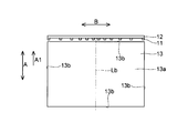
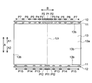
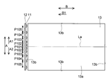
- FIG. 1 is a cross-sectional view illustrating a structure of a display device according to a first embodiment of the present invention. It is the figure which showed the structure of the light source and light guide plate of FIG. 1 from the light-projection surface side of the light guide plate. It is the figure which showed the structure of the light source and mounting substrate of FIG. 1 from the light-guide plate side. It is the figure which showed the structure around the light source of Example 1 from the light-projection surface side of the light-guide plate. It is the figure which showed the structure of the light source periphery of the comparative example 1 from the light-projection surface side of the light-guide plate.
- FIG. 6 is a diagram showing a luminance distribution on the light guide plate in the C1-C1 line of Example 1 and Comparative Example 1.
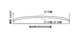
- FIG. 8 is a diagram illustrating a luminance distribution on the light guide plate along the C1-C1 line, the C2-C2 line, and the C3-C3 line of FIG. It is the figure which showed the luminance distribution on the light-guide plate in the C4-C4 line
- FIG. 6 is a cross-sectional view illustrating a structure of a display device according to a fourth embodiment of the present invention. It is the figure which showed the structure of the light source and light guide plate of FIG. 12 from the light-projection surface side of the light guide plate.
- FIG. 13 is a diagram for explaining the relationship between the operation of the display panel of FIG. 12 and light emission of a light source. It is the figure which showed the structure of the light source and light guide plate of the display apparatus by 5th Embodiment of this invention from the light-projection surface side of a light guide plate.
- FIG. 6 is a cross-sectional view illustrating a structure of a display device according to a fourth embodiment of the present invention. It is the figure which showed the structure of the light source and light guide plate of FIG. 12 from the light-projection surface side of the light guide plate.
- FIG. 13 is a diagram for explaining the relationship between the operation of the display panel of FIG. 12 and light emission of a light source. It is the figure which showed the structure of
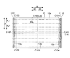
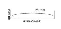
- FIG. 16 is a diagram showing a luminance distribution on the light guide plate taken along line C101-C101 in FIG.
- FIG. 16 is a diagram illustrating a luminance distribution on the light guide plate along C102-C102 line, C103-C103 line, and C104-C104 line of FIG. 15; It is a figure for demonstrating the electric power supplied to the light source of the display apparatus by 6th Embodiment of this invention. It is the figure which showed the luminance distribution on the light-guide plate of the display apparatus by 6th Embodiment of this invention. It is the figure which showed the structure of the backlight apparatus by an example of the past.
- the display device 1 constitutes, for example, a liquid crystal television receiver (not shown).
- the display device 1 includes a display panel 2 (illuminated member) and a lighting device 10 that is disposed on the back side of the display panel 2 and illuminates the display panel 2.
- the “rear surface (lower side in FIG. 1)” on the rear surface of the display panel 2 is an orientation concept applied to other components.
- the display device 1 can be placed vertically (placed with the display panel 2 standing in the vertical direction) or non-vertically placed.
- the non-vertical arrangement does not mean that the vertical arrangement is excluded, but the arrangement direction of the display panel 2 is not constant as in the case where the display device 1 is mounted on a portable device or the like, for example, display It means the case where the panel 2 is placed in the horizontal direction.
- display device 1 is arranged in a non-vertical manner
- a case where the display device 1 is arranged in a vertical manner will be described as necessary.
- the display panel 2 is composed of a liquid crystal display panel, and has two glass substrates that sandwich a liquid crystal layer (not shown).
- the display panel 2 displays an image by being illuminated by the illumination device 10.
- the lighting device 10 is an edge light type (also referred to as a side light type) backlight device, and guides light from a plurality of light sources 11, a mounting substrate 12 on which the plurality of light sources 11 are mounted, and a plurality of light sources 11.
- the light guide plate 13 that emits light
- the reflection sheet 14 that is disposed on the back side of the light guide plate 13
- the optical sheet 15 that is disposed on the light emitting surface 13a side of the light guide plate 13, and the backlight that is disposed on the back side thereof.
- a chassis 16 16.
- the light guide plate 13 has a function of guiding the light from the light source 11 while totally reflecting it and emitting it to the display panel 2 side. Further, as shown in FIG. 2, the light guide plate 13 includes a substantially rectangular light emitting surface 13a and four (four sides) side surfaces 13b. In this embodiment, one side surface (side surface on the A1 side) 13b on the long side of the four side surfaces 13b is a light incident surface. In order to simplify the description, the short direction of the light guide plate 13 is the A direction, and one side of the short direction is the A1 side. Moreover, let the longitudinal direction of the light-guide plate 13 be B direction.
- a processing portion (texture pattern, dot pattern, or prism) that changes the traveling direction of light incident from the side surface (light incident surface) 13b on the A1 side and emits light from the light exit surface 13a. Etc.) are formed. For this reason, the light that has reached the processed portion is reflected or refracted by the processed portion, so that the total reflection condition is not satisfied, and is emitted from the light emitting surface 13a to the display panel 2 side.
- the material of the light guide plate 13 include translucent resins such as polycarbonate resin and acrylic resin.
- the processed portion on the back surface of the light guide plate 13 is also center line Lb in the B direction of the light guide plate 13 Are formed symmetrically.
- the plurality of light sources 11 are arranged in the B direction (longitudinal direction of the light guide plate 13) along the side surface (light incident surface) 13b on the A1 side of the light guide plate 13.
- the light source 11 is configured to emit light toward the side surface (light incident surface) 13b on the A1 side.
- the light source 11 is comprised by LED which radiate
- the light source 11 may be composed of, for example, a red light emitting element, a green light emitting element, and a blue light emitting element, or may be composed of a blue light emitting element or an ultraviolet light emitting element and a phosphor.
- the plurality of light sources 11 are arranged at a predetermined pitch in the B direction and are arranged symmetrically with respect to the center line Lb in the B direction of the light guide plate 13.
- the arrangement pitch of the light sources 11 is P1, P2, P3, P4, P5, P6, and P7 in order from the center to the end in the B direction (arrangement direction)
- the B direction The arrangement pitch P1 of the light sources 11 in the center portion of the light source 11 is smaller than the arrangement pitch P7 of the light sources 11 at the end portion in the B direction. That is, the arrangement density of the light sources 11 in the central part in the B direction is higher than the arrangement density of the light sources 11 in the end part in the B direction.
- the arrangement pitch of the light sources 11 increases from the central portion in the B direction toward the end portion, and satisfies P1 ⁇ P2 ⁇ P3 ⁇ P4 ⁇ P5 ⁇ P6 ⁇ P7 (where P1 ⁇ P7). . That is, the arrangement density of the light sources 11 increases from the end in the B direction toward the center.
- the arrangement pitch of the light sources 11 preferably satisfies P1 ⁇ P2 ⁇ P3 ⁇ P4 ⁇ P5 ⁇ P6 ⁇ P7.
- the mounting substrate 12 is for supplying power to the light source 11, and may be formed so that the intensity of light emitted from the light source 11 can be adjusted for each light source 11.
- local dimming control for controlling the intensity of light emitted from each light source 11 in synchronization with the brightness of the display image can be performed. Thereby, it is possible to increase the contrast of the display image and reduce the power consumption of the lighting device 10.
- each light source 11 is supplied with the same amount of power, and the light emission amount of each light source 11 is substantially equal.
- the reflection sheet 14 has a function of reflecting light leaking from the back surface of the light guide plate 13 toward the light guide plate 13.
- the optical sheet 15 is composed of a plurality of sheets such as a diffusion plate, a prism sheet, and a lens sheet, and has a function of diffusing light from the light guide plate 13 or condensing it at a predetermined viewing angle. Note that the diffusion plate, the prism sheet, the lens sheet, and the like are provided as necessary and may be omitted.
- the backlight chassis 16 is formed of, for example, a metal plate.
- the arrangement density of the light sources 11 in the central part in the B direction is set higher than the arrangement density of the light sources 11 in the end part in the B direction.
- the arrangement density of the light sources 11 increases from the end toward the center.
- luminance of the display panel 2 can be gradually made high from an edge part toward a center part, and it can suppress that a brightness
- Example 1 As shown in FIG. 4, 14 light sources 11 were arranged along the side surface (light incident surface) 13b.
- the arrangement pitch of the light sources 11 is gradually increased from the central portion in the B direction toward the end portion, and is configured to satisfy P1 ⁇ P2 ⁇ P3 ⁇ P4 ⁇ P5 ⁇ P6 ⁇ P7.
- Other structures are the same as those in the first embodiment.
- Example 1 For Example 1 and Comparative Example 1, the luminance distribution on the light guide plate 13 at a position (line C1-C1 in FIGS. 4 and 5) located at a predetermined distance from the side surface (light incident surface) 13b was obtained. The result is shown in FIG.
- Example 1 has a higher brightness in the central portion in the B direction even though the number of light sources 11 is smaller than that in Comparative Example 1.
- the luminance at the center is set to the same value as in the prior art (Comparative Example 1), the number of light sources 11 can be further reduced and the power supplied to the light sources 11 can be reduced. did. It was also found that the luminance distribution is symmetric in the B direction.
- the plurality of light sources 11 are arranged along both long side surfaces 13 b (both side surfaces on the long side) of the four side surfaces 13 b of the light guide plate 13. Yes. That is, the plurality of light sources 11 are arranged along the side surface 13b (upper side surface) on the A1 side and the side surface 13b (lower side surface) on the A2 side (opposite side of the A1 side). Further, both the side surface 13b on the A1 side and the side surface 13b on the A2 side are light incident surfaces.
- the plurality of light sources 11 are arranged symmetrically with respect to the center line La in the A direction of the light guide plate 13. For this reason, the light sources 11 on the A2 side are arranged at the same arrangement pitch as the light sources 11 on the A1 side.
- the processed portion on the back surface of the light guide plate 13 is also in relation to the center lines La and Lb. Are formed symmetrically.
- the luminance at the center portion is higher than the luminance at the end portions in both the A direction and the B direction. Further, as shown in FIG. 8, it was found that the luminance distribution on the C1-C1 line and the luminance distribution on the C3-C3 line coincide. That is, it has been found that the luminance distribution is symmetric in the A direction. This is considered to be because the light source 11 is arranged symmetrically with respect to the center line La in the A direction of the light guide plate 13.
- the display device 1 is arranged vertically.
- the description will be made assuming that the A1 side is the upper side and the A2 side is the lower side.
- the temperature on the upper side (A1 side) of the lighting device 10 is higher than the temperature on the lower side (A2 side). That is, the ambient temperature of the upper light source 11 is higher than the ambient temperature of the lower light source 11. This is considered to be because the air containing the heat generated by the light source 11 moves upward and the heat rises above the lighting device 10.
- the light emission efficiency of the light source 11 decreases as the temperature during use increases. For this reason, when the display device 1 is used in a vertical arrangement, the light emission efficiency of the lower light source 11 is higher than the light emission efficiency of the upper light source 11. Thus, when the same amount of power is supplied to the upper light source 11 and the lower light source 11, the amount of light emitted from the lower plurality of light sources 11 is the amount of light emitted from the upper plurality of light sources 11. More than. For this reason, if the power supplied to the lower light source 11 is made smaller than the power supplied to the upper light source 11, the amount of light emitted from the lower light sources 11 is emitted from the upper light sources 11. It is possible to make it equal to the amount of light, and it is also possible to obtain the luminance distributions of FIGS. In this case, since the power supplied to the lower light source 11 is reduced, it is possible to reduce power consumption.
- the remaining structure of the second embodiment is the same as that of the first embodiment.
- the plurality of light sources 11 are arranged symmetrically with respect to the center line La in the A direction of the light guide plate 13.
- luminance of the A2 side part can be improved.
- the processed portion on the back surface of the light guide plate 13 may be formed symmetrically with respect to the center line La, the processed portion can be easily designed and manufactured.
- the power supplied to the lower light source 11 is smaller than the power supplied to the upper light source 11. Since the lower side of the light guide plate 13 is less likely to generate heat and less heat than the upper side, the lower light source 11 is less likely to have lower luminous efficiency. For this reason, by making the power supplied to the lower light source 11 smaller than the power supplied to the upper light source 11, the uniformity of the brightness of the upper part and the brightness of the lower part of the display panel 2 is improved. Can be improved.
- the third embodiment will be described assuming that the display device 1 is placed vertically, but the present invention can also be applied to the case where the display device 1 is placed vertically.
- the number (for example, 10) of light sources 11 on the A2 side (lower side) is equal to the number of light sources 11 on the A1 side (upper side) (for example, 14). Less).
- the arrangement pitch of the light sources 11 on the A2 side increases from the central portion in the B direction toward the end portion, and satisfies P11 ⁇ P12 ⁇ P13 ⁇ P14 ⁇ P15 (where P11 ⁇ P15).
- the arrangement density of the light sources 11 on the A2 side increases from the end in the B direction toward the center.
- the arrangement pitch of the light sources 11 on the A2 side preferably satisfies P11 ⁇ P12 ⁇ P13 ⁇ P14 ⁇ P15.
- the light source 11 on the A2 side is also arranged symmetrically with respect to the center line Lb in the B direction of the light guide plate 13.
- the remaining structure of the third embodiment is the same as that of the second embodiment.
- the plurality of light sources 11 are arranged along the side surfaces 13b on both the A1 side and the A2 side of the light guide plate 13. Thereby, even if the number of the light sources 11 on the A1 side is different from the number of the light sources 11 on the A2 side, the display panel 2 is compared with the case where the light sources 11 are arranged only on the A1 side as in the first embodiment. The uniformity of the luminance of the A1 side portion and the luminance of the A2 side portion can be improved.
- the upper side (A1 side) light source 11 and the lower side (A2 side) light source 11 have the same size.
- the amount of light emitted from the lower light source 11 is larger than the amount of light emitted from the upper light source 11.
- the luminance of the upper part of the display panel 2 and the lower side of the display panel 2 are reduced by making the number of the lower light sources 11 smaller than the number of the upper light sources 11. The uniformity with the luminance of the part can be improved.
- a display device 1 according to the fourth embodiment will be described with reference to FIGS.
- a display device 1 according to the fourth embodiment unlike the first to third embodiments, a case where a plurality of light sources 11 are arranged along one side surface (side surface on the B1 side) 13b on the short side of the light guide plate 13 will be described. .
- the plurality of light sources 11 are arranged along one side surface (side surface on the B1 side) 13 b on the short side of the four side surfaces 13 b of the light guide plate 13. ing.
- the B1 side surface 13b of the four side surfaces 13b is a light incident surface.
- one side in the longitudinal direction of the light guide plate 13 is defined as the B1 side.
- the plurality of light sources 11 are arranged at a predetermined pitch in the A direction and are arranged symmetrically with respect to the center line La in the A direction of the light guide plate 13.
- the arrangement pitch of the light sources 11 is P101, P102, P103, P104, and P105 in order from the central portion in the A direction (arrangement direction) to the end portion
- the arrangement pitch P101 of the light sources 11 in the central portion in the A direction Is smaller than the arrangement pitch P105 of the light sources 11 at the end in the A direction. That is, the arrangement density of the light sources 11 in the central part in the A direction is higher than the arrangement density of the light sources 11 in the end part in the A direction.
- the arrangement pitch of the light sources 11 increases from the center in the A direction toward the end, and satisfies P101 ⁇ P102 ⁇ P103 ⁇ P104 ⁇ P105 (where P101 ⁇ P105). That is, the arrangement density of the light sources 11 increases from the end in the A direction toward the center.
- the arrangement pitch of the light sources 11 preferably satisfies P101 ⁇ P102 ⁇ P103 ⁇ P104 ⁇ P105.
- the display panel 2 is configured to operate from the A1 side to the A2 side.
- the light source 11 emits light sequentially from the A1 side to the A2 side in synchronization with the operation of the display panel 2 with the light emission timings of the plurality of light sources 11.
- the remaining structure of the fourth embodiment is similar to that of the aforementioned first embodiment.
- the plurality of light sources 11 are arranged along the side surface 13b on the B1 side of the light guide plate 13. Thereby, the light source 11 can be made to emit light in order from the A1 side to the A2 side in synchronization with the operation of the display panel 2 at the light emission timings of the plurality of light sources 11. In this case, the afterimage effect of the display panel 2 can be suppressed and the moving image display performance can be improved. Further, if the light source 11 is made non-light emitting in a region of the display panel 2 where the operation is OFF (a region where the backlight is not transmitted), the power consumption of the lighting device 10 can be reduced.
- the plurality of light sources 11 are arranged along both side surfaces 13 b (both side surfaces on the short side) of the short side of the four side surfaces 13 b of the light guide plate 13. Yes. That is, the plurality of light sources 11 are arranged along the side surface 13b on the B1 side and the side surface 13b on the B2 side (the side opposite to the B1 side). Further, both the side surface 13b on the B1 side and the side surface 13b on the B2 side are light incident surfaces.
- the plurality of light sources 11 are arranged symmetrically with respect to the center line Lb in the B direction of the light guide plate 13. For this reason, the light sources 11 on the B2 side are arranged at the same arrangement pitch as the light sources 11 on the B1 side.
- the processed portion on the back surface of the light guide plate 13 is also in relation to the center lines La and Lb. Are formed symmetrically.
- the luminance at the center portion is higher than the luminance at the end portions in both the A direction and the B direction. Further, as shown in FIG. 17, it was found that the luminance distribution on the C102-C102 line and the luminance distribution on the C104-C104 line coincide. That is, it has been found that the luminance distribution is symmetric in the B direction. This is considered to be because the light source 11 is arranged symmetrically with respect to the center line Lb in the B direction of the light guide plate 13.
- the remaining structure of the fifth embodiment is similar to that of the aforementioned fourth embodiment.
- the plurality of light sources 11 are arranged symmetrically with respect to the center line Lb in the B direction of the light guide plate 13.
- luminance of the B2 side part can be improved.
- the processed portion on the back surface of the light guide plate 13 may be formed symmetrically with respect to the center line Lb, the processed portion can be easily designed and manufactured.
- the power supplied to the light source 11 at the end in the arrangement direction is larger than the power supplied to the light source 11 at the center in the arrangement direction.
- the power supplied to the light source 11 is Q1, Q2, Q3, Q4, and Q5 in order from the center to the end in the A direction (arrangement direction)
- the power supplied to the light source 11 is It becomes larger as it goes from the central part in the A direction toward the end part, and satisfies Q1 ⁇ Q2 ⁇ Q3 ⁇ Q4 ⁇ Q5 (Q1 ⁇ Q5).
- the power supplied to the light source 11 preferably satisfies Q1 ⁇ Q2 ⁇ Q3 ⁇ Q4 ⁇ Q5.
- the power when the power supplied to all the light sources 11 is equal is indicated by a triangle mark and a broken line.
- the luminance distribution at a predetermined position (C103-C103 line in FIG. 15) was obtained in the same manner as in the fifth embodiment. The result is shown in FIG. In FIG. 19, the luminance distribution in the case where the power supplied to all the light sources 11 is equal is indicated by a broken line.
- the remaining structure of the sixth embodiment is similar to that of the aforementioned fifth embodiment.
- the power supplied to the light source 11 at the end in the arrangement direction is made larger than the power supplied to the light source 11 at the center in the arrangement direction.
- the present invention is not limited thereto, and may be applied to a display panel other than the liquid crystal display panel.
- the backlight apparatus which illuminates a display panel was demonstrated as an example of an illuminating device, this invention is applicable not only to this but the illuminating device which illuminates to-be-illuminated members other than a display panel. is there.
- the light source is arranged along one or two of the four side surfaces of the light guide plate, but the present invention is not limited to this.
- the light sources may be arranged along three or four of the four side surfaces of the light guide plate.
- the A1 side light source and the A2 side light source are arranged symmetrically.
- the present invention is not limited to this.
- the light source on the A1 side and the light source on the A2 side need not be arranged symmetrically.
- the number of light sources on the A1 side and the number of light sources on the A2 side may be the same, and only the arrangement pitch may be varied. The same applies to the case where the light sources are arranged along the two side surfaces on the short side of the light guide plate.
- the power supplied to the light source at the end may be larger than the power supplied to the light source at the center.
- Display device 2 Display panel (illuminated member) DESCRIPTION OF SYMBOLS 10 Illuminating device 11 Light source 13 Light guide plate 13b Side surface La, Lb Centerline Q1-Q5 Electric power
Landscapes
- Physics & Mathematics (AREA)
- Nonlinear Science (AREA)
- General Physics & Mathematics (AREA)
- Optics & Photonics (AREA)
- Mathematical Physics (AREA)
- Chemical & Material Sciences (AREA)
- Crystallography & Structural Chemistry (AREA)
- Planar Illumination Modules (AREA)
Abstract
被照明部材の中央部の輝度を確保しながら、光源の数を少なくすることが可能な照明装置を提供する。この照明装置(10)は、複数の光源(11)と、光源からの光が入射され、光源からの光を導光する導光板(13)と、を備える。複数の光源は導光板の少なくとも1つの側面(13b)に沿って配列され、複数の光源の配列方向の中央部における光源の配置密度は、複数の光源の配列方向の端部における光源の配置密度よりも高い。
Description
この発明は、照明装置および表示装置に関し、特に、複数の光源と、光源からの光を導光する導光板とを備えた照明装置および表示装置に関する。
非発光型の表示パネル(被照明部材)を搭載する液晶表示装置(表示装置)には、通常、表示パネルに対して光を照射するバックライト装置(照明装置)も搭載される。このようなバックライト装置として、複数のLED(光源)と、LEDからの光を導光する導光板とを備えたバックライト装置が知られている。
図20は、従来の一例によるバックライト装置の構造を示した図である。従来の一例によるバックライト装置1001は図20に示すように、複数のLED1002と、複数のLED1002が実装された実装基板1003と、複数のLED1002からの光を導光する導光板1004とを備えている。導光板1004は表示パネル(図示せず)側に光を出射する光出射面1004aと、4つ(四辺)の側面1004bとを含んでいる。複数のLED1002は導光板1004の、図において上側の側面1004bに沿って配列されている。また、複数のLED1002は等しいピッチで配列されている。
なお、導光板の側面に沿って複数の光源が配列されるバックライト装置は、例えば特許文献1に開示されている。
しかしながら、図20に示したバックライト装置1001では、コスト低減のためにLED1002の数を少なくすると、表示パネルの輝度が低下するので、表示パネルの中央部の輝度が低下するという問題点がある。表示パネルの中央部の輝度が端部(周辺部)の輝度よりも高ければ、心理的あるいは生理的な錯覚により表示パネル全体の輝度が高く見えるので、中央部の輝度を確保することは重要である。
この発明は、上記のような課題を解決するためになされたものであり、この発明の目的は、被照明部材の中央部の輝度を確保しながら、光源の数を少なくすることが可能な照明装置および表示装置を提供することである。
上記目的を達成するために、この発明の照明装置は、被照明部材の背面側に配置される照明装置であって、複数の光源と、光源からの光が入射され、光源からの光を導光する導光板と、を備え、複数の光源は導光板の少なくとも1つの側面に沿って配列され、複数の光源の配列方向の中央部における光源の配置密度は、複数の光源の配列方向の端部における光源の配置密度よりも高い。
この照明装置では、上記のように、複数の光源の配列方向の中央部における光源の配置密度を、複数の光源の配列方向の端部における光源の配置密度よりも高くすることによって、被照明部材の中央部の輝度は端部の輝度よりも高くなる。
上記照明装置において、好ましくは、光源の配置密度は端部から中央部に向かうにしたがって高くなる。このように構成すれば、被照明部材の輝度を端部から中央部に向かって徐々に高くすることができ、被照明部材に輝度ムラが発生するのを抑制することができる。
上記照明装置において、複数の光源は導光板の短辺側の少なくとも1つの側面に沿って配列されていてもよい。
上記複数の光源が導光板の短辺側の側面に沿って配列されている照明装置において、好ましくは、複数の光源は導光板の短辺側の両側面に沿って配列されている。
上記複数の光源が導光板の短辺側の両側面に沿って配列されている照明装置において、好ましくは、複数の光源は導光板の長手方向の中心線に対して対称に配置されている。
上記照明装置において、複数の光源は導光板の長辺側の少なくとも1つの側面に沿って配列されていてもよい。
上記複数の光源が導光板の長辺側の側面に沿って配列されている照明装置において、好ましくは、複数の光源は導光板の長辺側の両側面に沿って配列されている。
上記複数の光源が導光板の長辺側の両側面に沿って配列されている照明装置において、好ましくは、複数の光源は導光板の短手方向の中心線に対して対称に配置されている。
上記照明装置において、好ましくは、端部の光源に供給される電力は、中央部の光源に供給される電力よりも大きい。
上記照明装置において、複数の光源は導光板の上辺側の側面および下辺側の側面に沿って配列され、下辺側の側面に沿って配列される光源の数は、上辺側の側面に沿って配列される光源の数よりも少なくてもよい。
上記照明装置において、好ましくは、複数の光源は導光板の上辺側の側面および下辺側の側面に沿って配列され、下辺側の側面に沿って配列される光源に供給される電力は、上辺側の側面に沿って配列される光源に供給される電力よりも小さい。
この発明の表示装置は、上記の構成の照明装置と、照明装置に照明される表示パネルとを備える。
以上のように、本発明によれば、複数の光源の配列方向の中央部における光源の配置密度を、複数の光源の配列方向の端部における光源の配置密度よりも高くすることによって、被照明部材の中央部の輝度は端部の輝度よりも高くなる。これにより、光源の数を少なくした場合であっても、被照明部材の中央部の輝度を確保することができる。また、光源の数を少なくできるので、照明装置を軽量化および低コスト化することができる。
以下、本発明の実施形態について図面を参照して説明する。なお、理解を容易にするために、断面図であってもハッチングを施さない場合がある。
(第1実施形態)
まず、図1~図3を参照して、本発明の第1実施形態による表示装置1の構造について説明する。
まず、図1~図3を参照して、本発明の第1実施形態による表示装置1の構造について説明する。
本発明の第1実施形態による表示装置1は例えば液晶テレビジョン受像機(図示せず)などを構成するものである。また、表示装置1は図1に示すように、表示パネル2(被照明部材)と、表示パネル2の背面側に配置され、表示パネル2を照明する照明装置10とによって構成されている。なお、表示パネル2の背面の「背面(図1では下側)」は、他の構成要素にも適用される方位概念である。また、表示装置1は縦置き配置(表示パネル2を鉛直方向に立てて配置)や非縦置き配置することが可能である。ここで、非縦置き配置とは、縦置き配置を除外するという意味ではなく、表示装置1を携帯機器等に搭載する場合のように表示パネル2の配置方向が一定ではない場合や、例えば表示パネル2を水平方向に寝かせて配置する場合を意味する。以下の説明では主として表示装置1を非縦置き配置する場合について説明し、必要に応じて表示装置1を縦置き配置する場合についても説明する。
表示パネル2は液晶表示パネルからなり、図示しない液晶層を挟み込む2つのガラス基板を有する。また、表示パネル2は照明装置10に照明されることにより画像を表示する。
照明装置10はエッジライト型(サイドライト型とも言う)のバックライト装置であって、複数の光源11と、複数の光源11が実装される実装基板12と、複数の光源11からの光を導光する導光板13と、導光板13の背面側に配置される反射シート14と、導光板13の光出射面13a側に配置される光学シート15と、これらの背面側に配置されるバックライトシャーシ16とを含んでいる。
導光板13は光源11からの光を全反射させながら導光し表示パネル2側に出射する機能を有する。また、導光板13は図2に示すように、略矩形状の光出射面13aと、4つ(四辺)の側面13bとを含んでいる。本実施形態では、4つの側面13bのうちの長辺側の一方の側面(A1側の側面)13bが光入射面となっている。なお、説明を簡単にするために、導光板13の短手方向をA方向とし、短手方向の一方側をA1側とする。また、導光板13の長手方向をB方向とする。
また、導光板13の背面には、A1側の側面(光入射面)13bから入射した光の進行方向を変更して光出射面13aから光を出射させる加工部(シボパターン、ドットパターンまたはプリズムなど)が形成されている。このため、加工部に到達した光は、加工部で反射や屈折されることにより全反射条件を満たさなくなり、光出射面13aから表示パネル2側に出射される。導光板13の材質としては例えばポリカーボネート樹脂やアクリル樹脂などの透光性を有する樹脂が挙げられる。
なお、後述するように複数の光源11は導光板13のB方向の中心線Lbに対して対称に配置されるので、導光板13の背面の加工部も導光板13のB方向の中心線Lbに対して対称に形成されている。
複数の光源11は導光板13のA1側の側面(光入射面)13bに沿ってB方向(導光板13の長手方向)に配列されている。また、光源11はA1側の側面(光入射面)13bに向かって光を出射するように構成されている。また、光源11は例えば白色光を出射するLEDにより構成されている。この場合、光源11は例えば赤色発光素子、緑色発光素子および青色発光素子により構成されていてもよいし、青色発光素子または紫外光発光素子と蛍光体となどにより構成されていてもよい。
複数の光源11はB方向に所定のピッチで配列されているとともに、導光板13のB方向の中心線Lbに対して対称に配置されている。ここで、図3に示すように、光源11の配置ピッチをB方向(配列方向)の中央部から端部に向かって順にP1、P2、P3、P4、P5、P6、P7とすると、B方向の中央部における光源11の配置ピッチP1は、B方向の端部における光源11の配置ピッチP7よりも小さい。すなわち、B方向の中央部における光源11の配置密度は、B方向の端部における光源11の配置密度よりも高い。
また、光源11の配置ピッチは、B方向の中央部から端部に向かうにしたがって大きくなっており、P1≦P2≦P3≦P4≦P5≦P6≦P7(ただし、P1<P7)を満たしている。すなわち、光源11の配置密度はB方向の端部から中央部に向かうにしたがって高くなっている。なお、光源11の配置ピッチは、P1<P2<P3<P4<P5<P6<P7を満たすことが好ましい。
また、複数の光源11は図2に示すように、実装基板12に実装されている。この実装基板12は光源11に電力を供給するためのものであり、光源11から出射する光の強度を光源11毎に調整することが可能となるように形成されていてもよい。この場合、表示画像の明暗と同期して各光源11から出射する光の強度を制御するローカルディミング制御を行うことが可能となる。これにより、表示画像を高コントラスト化することが可能となるとともに、照明装置10の消費電力を低減することが可能となる。なお、以下の説明では特に記載がある場合を除き、各光源11には等しい大きさの電力が供給され、各光源11の発光量は略等しいものとする。
図1に示すように、反射シート14は導光板13の背面から漏れた光を導光板13側に反射する機能を有する。光学シート15は拡散板、プリズムシートおよびレンズシートなどの複数のシート類により構成されており、導光板13からの光を拡散させたり所定の視野角に集光する機能を有する。なお、拡散板、プリズムシートおよびレンズシートなどは、必要に応じて設けられるものであり、無くてもよい。バックライトシャーシ16は、例えば金属板により形成されている。
本実施形態では、上記のように、B方向(配列方向)の中央部における光源11の配置密度を、B方向の端部における光源11の配置密度よりも高くする。これにより、導光板13のB方向の中央部上の輝度は端部上の輝度よりも高くなるので、表示パネル2のB方向の中央部の輝度は端部の輝度よりも高くなる。このため、光源11の数を少なくした場合であっても、表示パネル2の中央部の輝度を確保することができる。また、光源11の数を少なくできるので、照明装置10を軽量化および低コスト化することができる。
また、上記のように、光源11の配置密度は端部から中央部に向かうにしたがって高くなる。これにより、表示パネル2の輝度を端部から中央部に向かって徐々に高くすることができ、表示パネル2に輝度ムラが発生するのを抑制することができる。
次に、図4~図6を参照して、上記した効果を確認するために行った確認実験について説明する。
この確認実験では、第1実施形態に対応した実施例1と、光源11の配置ピッチを等しくした比較例1とについて、所定の位置における導光板13上の輝度分布をシミュレーションにより求めた。
実施例1では図4に示すように、光源11を側面(光入射面)13bに沿って14個配列した。また、光源11の配置ピッチを、B方向の中央部から端部に向かうにしたがって徐々に大きくし、P1<P2<P3<P4<P5<P6<P7を満たすように構成した。なお、その他の構造は、上記第1実施形態と同様にした。
比較例1では図5に示したように、光源11を側面(光入射面)13bに沿って18個配列した。また、光源11の配置ピッチを全て等しくし、p1=p2=p3=p4=p5=p6=p7=p8=p9を満たすように構成した。なお、その他の構造は、実施例1と同様にした。
そして、実施例1および比較例1について、側面(光入射面)13bから所定の距離だけ内側の位置(図4および図5のC1-C1線)における導光板13上の輝度分布を求めた。その結果を図6に示す。
図6を参照して、実施例1は比較例1に比べて光源11の数を少なくしているにもかかわらず、B方向の中央部の輝度が高くなることが判明した。これにより、中央部の輝度を従来(比較例1)と同じ値にするのであれば、光源11の数をさらに減らすことや、光源11に供給する電力を小さくすることが可能であることが判明した。また、輝度分布がB方向に対称になることが判明した。
(第2実施形態)
この第2実施形態では図7~図10を参照して、上記第1実施形態と異なり、複数の光源11を導光板13の2つの側面13bに沿って配列する場合について説明する。
この第2実施形態では図7~図10を参照して、上記第1実施形態と異なり、複数の光源11を導光板13の2つの側面13bに沿って配列する場合について説明する。
第2実施形態では図7に示すように、複数の光源11は導光板13の4つの側面13bのうちの長辺側の両方の側面13b(長辺側の両側面)に沿って配列されている。すなわち、複数の光源11はA1側の側面13b(上辺側の側面)と、A2側(A1側とは反対側)の側面13b(下辺側の側面)とに沿って配列されている。また、A1側の側面13bとA2側の側面13bとの両方が光入射面となっている。
また、複数の光源11は導光板13のA方向の中心線Laに対して対称に配置されている。このため、A2側の光源11はA1側の光源11と同じ配置ピッチで配置されている。
なお、複数の光源11は導光板13のA方向の中心線LaおよびB方向の中心線Lbに対して対称に配置されるので、導光板13の背面の加工部も中心線LaおよびLbに対して対称に形成されている。
この構成において、所定の位置(図7のC1-C1線、C2-C2線、C3-C3線、C4-C4線)における導光板13上の輝度分布を上記第1実施形態と同様に求めた。その結果を図8および図9に示す。
図8および図9を参照して、A方向およびB方向の両方向において、中央部の輝度が端部の輝度よりも高くなることが判明した。また、図8に示すように、C1-C1線における輝度分布とC3-C3線における輝度分布とが一致することが判明した。すなわち、輝度分布がA方向に対称になることが判明した。これは、導光板13のA方向の中心線Laに対して対称に光源11を配置しているためであると考えられる。
次に、表示装置1を縦置き配置する場合について説明する。ここでは、A1側を上側、A2側を下側として説明する。
本実施形態の表示装置1を縦置き配置して使用した場合、図10に示すように、照明装置10の上側(A1側)の温度が下側(A2側)の温度よりも高くなる。すなわち、上側の光源11の周囲温度が下側の光源11の周囲温度よりも高くなる。これは、光源11で発生した熱を含んだ空気が上側に移動し、照明装置10の上側で熱が籠るためであると考えられる。
光源11は使用時の温度が高くなると発光効率が低下する。このため、表示装置1を縦置き配置して使用した場合、下側の光源11の発光効率は上側の光源11の発光効率よりも高くなる。これにより、上側の光源11と下側の光源11とに同じ大きさの電力を供給すると、下側の複数の光源11から出射する光の量が上側の複数の光源11から出射する光の量よりも多くなる。このため、下側の光源11に供給する電力を上側の光源11に供給する電力よりも小さくすれば、下側の複数の光源11から出射する光の量を上側の複数の光源11から出射する光の量と等しくすることが可能であり、図8および図9の輝度分布を得ることも可能である。この場合、下側の光源11に供給する電力を小さくするので、消費電力を低減することが可能である。
なお、第2実施形態のその他の構造は、上記第1実施形態と同様である。
本実施形態では、上記のように、複数の光源11を導光板13のA方向の中心線Laに対して対称に配置する。これにより、表示パネル2のA1側の部分の輝度とA2側の部分の輝度との均一性を向上させることができる。また、導光板13の背面の加工部を中心線Laに対して対称に形成すればよいので、加工部を容易に設計・製造できる。
また、上記のように、表示装置1を縦置き配置する場合、下側の光源11に供給される電力は、上側の光源11に供給される電力よりも小さい。導光板13の下側は上側に比べて熱が籠りにくく高温になりにくいので、下側の光源11は発光効率が低下しにくい。このため、下側の光源11に供給する電力を、上側の光源11に供給する電力よりも小さくすることによって、表示パネル2の上側の部分の輝度と下側の部分の輝度との均一性を向上させることができる。
第2実施形態のその他の効果は、上記第1実施形態と同様である。
(第3実施形態)
この第3実施形態では表示装置1を縦置き配置する場合を想定して説明するが、表示装置1を非縦置き配置する場合にも適用可能である。第3実施形態では図11に示すように、上記第2実施形態と異なり、A2側(下側)の光源11の数(例えば10個)はA1側(上側)の光源11の数(例えば14個)よりも少ない。また、A2側の光源11の配置ピッチは、B方向の中央部から端部に向かうにしたがって大きくなっており、P11≦P12≦P13≦P14≦P15(ただし、P11<P15)を満たしている。すなわち、A2側の光源11の配置密度はB方向の端部から中央部に向かうにしたがって高くなっている。なお、A2側の光源11の配置ピッチは、P11<P12<P13<P14<P15を満たすことが好ましい。また、A2側の光源11も、導光板13のB方向の中心線Lbに対して対称に配置される。
この第3実施形態では表示装置1を縦置き配置する場合を想定して説明するが、表示装置1を非縦置き配置する場合にも適用可能である。第3実施形態では図11に示すように、上記第2実施形態と異なり、A2側(下側)の光源11の数(例えば10個)はA1側(上側)の光源11の数(例えば14個)よりも少ない。また、A2側の光源11の配置ピッチは、B方向の中央部から端部に向かうにしたがって大きくなっており、P11≦P12≦P13≦P14≦P15(ただし、P11<P15)を満たしている。すなわち、A2側の光源11の配置密度はB方向の端部から中央部に向かうにしたがって高くなっている。なお、A2側の光源11の配置ピッチは、P11<P12<P13<P14<P15を満たすことが好ましい。また、A2側の光源11も、導光板13のB方向の中心線Lbに対して対称に配置される。
なお、第3実施形態のその他の構造は、上記第2実施形態と同様である。
本実施形態では、上記のように、複数の光源11を導光板13のA1側およびA2側の両方の側面13bに沿って配列する。これにより、A1側の光源11の数とA2側の光源11の数とが異なっていても、上記第1実施形態のようにA1側のみに光源11を配置する場合に比べて、表示パネル2のA1側の部分の輝度とA2側の部分の輝度との均一性を向上させることができる。
また、上記第2実施形態で説明したように、表示装置1を縦置き配置して使用する場合、上側(A1側)の光源11と下側(A2側)の光源11とに同じ大きさの電力を供給すると、下側の光源11から出射する光の量が上側の光源11から出射する光の量よりも多くなる。このため、表示装置1を縦置き配置して使用する場合、下側の光源11の数を上側の光源11の数よりも少なくすることによって、表示パネル2の上側の部分の輝度と下側の部分の輝度との均一性を向上させることができる。
第3実施形態のその他の効果は、上記第1および第2実施形態と同様である。
(第4実施形態)
次に、図12~図14を参照して、第4実施形態による表示装置1について説明する。この第4実施形態では、上記第1~第3実施形態と異なり、複数の光源11を導光板13の短辺側の一方の側面(B1側の側面)13bに沿って配列する場合について説明する。
次に、図12~図14を参照して、第4実施形態による表示装置1について説明する。この第4実施形態では、上記第1~第3実施形態と異なり、複数の光源11を導光板13の短辺側の一方の側面(B1側の側面)13bに沿って配列する場合について説明する。
第4実施形態では図12および図13に示すように、複数の光源11は導光板13の4つの側面13bのうちの短辺側の一方の側面(B1側の側面)13bに沿って配列されている。本実施形態では、4つの側面13bのうちのB1側の側面13bが光入射面となっている。なお、説明を簡単にするために、導光板13の長手方向の一方側をB1側とする。
複数の光源11は図13に示すように、A方向に所定のピッチで配列されているとともに、導光板13のA方向の中心線Laに対して対称に配置されている。ここで、光源11の配置ピッチを、A方向(配列方向)の中央部から端部に向かって順にP101、P102、P103、P104、P105とすると、A方向の中央部における光源11の配置ピッチP101は、A方向の端部における光源11の配置ピッチP105よりも小さい。すなわち、A方向の中央部における光源11の配置密度は、A方向の端部における光源11の配置密度よりも高い。
また、光源11の配置ピッチは、A方向の中央部から端部に向かうにしたがって大きくなっており、P101≦P102≦P103≦P104≦P105(ただし、P101<P105)を満たしている。すなわち、光源11の配置密度はA方向の端部から中央部に向かうにしたがって高くなっている。なお、光源11の配置ピッチは、P101<P102<P103<P104<P105を満たすことが好ましい。
また、図14に示すように、表示パネル2はA1側からA2側に動作するように構成されている。また、複数の光源11の発光タイミングが表示パネル2の動作に同期して、A1側からA2側に順に光源11が発光する。
なお、第4実施形態のその他の構造は、上記第1実施形態と同様である。
本実施形態では、上記のように、複数の光源11を導光板13のB1側の側面13bに沿って配列する。これにより、複数の光源11の発光タイミングを表示パネル2の動作に同期させて、A1側からA2側に順に光源11を発光させることができる。この場合、表示パネル2の残像効果を抑制することができるとともに、動画表示性能を向上させることができる。また、表示パネル2のうちの動作OFFの領域(バックライト光を透過しない領域)において光源11を非発光にすれば、照明装置10の消費電力を低減することができる。
第4実施形態のその他の効果は、上記第1実施形態と同様である。
(第5実施形態)
この第5実施形態では図15~図17を参照して、上記第4実施形態と異なり、複数の光源11を導光板13の短辺側の2つの側面13bに沿って配列する場合について説明する。
この第5実施形態では図15~図17を参照して、上記第4実施形態と異なり、複数の光源11を導光板13の短辺側の2つの側面13bに沿って配列する場合について説明する。
第5実施形態では図15に示すように、複数の光源11は導光板13の4つの側面13bのうちの短辺側の両方の側面13b(短辺側の両側面)に沿って配列されている。すなわち、複数の光源11はB1側の側面13bと、B2側(B1側とは反対側)の側面13bとに沿って配列されている。また、B1側の側面13bとB2側の側面13bとの両方が光入射面となっている。
また、複数の光源11は導光板13のB方向の中心線Lbに対して対称に配置されている。このため、B2側の光源11はB1側の光源11と同じ配置ピッチで配置されている。
なお、複数の光源11は導光板13のA方向の中心線LaおよびB方向の中心線Lbに対して対称に配置されるので、導光板13の背面の加工部も中心線LaおよびLbに対して対称に形成されている。
この構成において、所定の位置(図15のC101-C101線、C102-C102線、C103-C103線、C104-C104線)における導光板13上の輝度分布を上記第2実施形態と同様に求めた。その結果を図16および図17に示す。
図16および図17を参照して、A方向およびB方向の両方向において、中央部の輝度が端部の輝度よりも高くなることが判明した。また、図17に示すように、C102-C102線における輝度分布とC104-C104線における輝度分布とが一致することが判明した。すなわち、輝度分布がB方向に対称になることが判明した。これは、導光板13のB方向の中心線Lbに対して対称に光源11を配置しているためであると考えられる。
なお、第5実施形態のその他の構造は、上記第4実施形態と同様である。
本実施形態では、上記のように、複数の光源11を導光板13のB方向の中心線Lbに対して対称に配置する。これにより、表示パネル2のB1側の部分の輝度とB2側の部分の輝度との均一性を向上させることができる。また、導光板13の背面の加工部を中心線Lbに対して対称に形成すればよいので、加工部を容易に設計・製造できる。
第5実施形態のその他の効果は、上記第4実施形態と同様である。
(第6実施形態)
この第6実施形態では図18および図19を参照して、上記第1~第5実施形態と異なり、複数の光源11のうちの配列方向の端部の光源11に供給される電力が、配列方向の中央部の光源11に供給される電力よりも大きい場合について説明する。
この第6実施形態では図18および図19を参照して、上記第1~第5実施形態と異なり、複数の光源11のうちの配列方向の端部の光源11に供給される電力が、配列方向の中央部の光源11に供給される電力よりも大きい場合について説明する。
第6実施形態では図18に示すように、配列方向(A方向)の端部の光源11に供給される電力は、配列方向の中央部の光源11に供給される電力よりも大きい。具体的には、光源11に供給される電力をA方向(配列方向)の中央部から端部に向かって順にQ1、Q2、Q3、Q4、Q5とすると、光源11に供給される電力は、A方向の中央部から端部に向かうにしたがって大きくなっており、Q1≦Q2≦Q3≦Q4≦Q5(ただし、Q1<Q5)を満たしている。また、光源11に供給される電力は、Q1<Q2<Q3<Q4<Q5を満たすことが好ましい。なお、図18には、全ての光源11に供給される電力を等しくした場合の電力を三角マークおよび破線で示している。
この構成において、所定の位置(図15のC103-C103線)における輝度分布を上記第5実施形態と同様に求めた。その結果を図19に示す。なお、図19には、全ての光源11に供給される電力を等しくした場合の輝度分布を破線で示している。
図19を参照して、全ての光源11に供給される電力を等しくする場合に比べて、A方向の端部の輝度が高くなるとともに、輝度の均一性が向上することが判明した。
なお、第6実施形態のその他の構造は、上記第5実施形態と同様である。
本実施形態では、上記のように、配列方向の端部の光源11に供給される電力を、配列方向の中央部の光源11に供給される電力よりも大きくする。これにより、導光板13の端部上の輝度が中央部上の輝度よりも低くなりすぎるのを抑制することができるので、表示パネル2の端部の輝度が中央部の輝度よりも低くなりすぎるのを抑制することができる。このため、表示パネル2の輝度の均一性をより向上させることができる。
第6実施形態のその他の効果は、上記第5実施形態と同様である。
なお、今回開示された実施形態および実施例は、すべての点で例示であって制限的なものではないと考えられるべきである。本発明の範囲は、上記した実施形態および実施例の説明ではなく請求の範囲によって示され、さらに請求の範囲と均等の意味および範囲内でのすべての変更が含まれる。
例えば、上記実施形態では、表示パネルを液晶表示パネルに適用した例について示したが、本発明はこれに限らず、液晶表示パネル以外の表示パネルに適用してもよい。
また、上記実施形態では、照明装置の一例として表示パネルを照明するバックライト装置について説明したが、本発明はこれに限らず、表示パネル以外の被照明部材を照明する照明装置にも適用可能である。
また、上記実施形態では、光源を導光板の4つの側面のうちの1つまたは2つの側面に沿って配列した例について示したが、本発明はこれに限らない。光源を導光板の4つの側面のうちの3つまたは4つの側面に沿って配列してもよい。
また、例えば上記第2実施形態では、光源を導光板の長辺側の2つの側面に沿って配列する場合に、A1側の光源とA2側の光源とを対称に配置した例について示したが、本発明はこれに限らない。A1側の光源とA2側の光源とを対称に配置しなくてもよい。例えば、A1側の光源の数とA2側の光源の数とを同じにして、配置ピッチだけを異ならせてもよい。このことは、光源を導光板の短辺側の2つの側面に沿って配列する場合も同様である。
また、上記第6実施形態では、上記第5実施形態と同様の構成において、端部の光源に供給する電力を中央部の光源に供給する電力よりも大きくした例について示したが、本発明はこれに限らない。上記第1~第4実施形態の構成においても、端部の光源に供給する電力を中央部の光源に供給する電力よりも大きくしてもよい。
1 表示装置
2 表示パネル(被照明部材)
10 照明装置
11 光源
13 導光板
13b 側面
La、Lb 中心線
Q1~Q5 電力
2 表示パネル(被照明部材)
10 照明装置
11 光源
13 導光板
13b 側面
La、Lb 中心線
Q1~Q5 電力
Claims (12)
- 被照明部材の背面側に配置される照明装置であって、
複数の光源と、
前記光源からの光が入射され、前記光源からの光を導光する導光板と、
を備え、
前記複数の光源は前記導光板の少なくとも1つの側面に沿って配列され、
前記複数の光源の配列方向の中央部における前記光源の配置密度は、前記複数の光源の配列方向の端部における前記光源の配置密度よりも高いことを特徴とする照明装置。 - 前記光源の配置密度は前記端部から前記中央部に向かうにしたがって高くなることを特徴とする請求項1に記載の照明装置。
- 前記複数の光源は前記導光板の短辺側の少なくとも1つの側面に沿って配列されていることを特徴とする請求項1または2に記載の照明装置。
- 前記複数の光源は前記導光板の短辺側の両側面に沿って配列されていることを特徴とする請求項3に記載の照明装置。
- 前記複数の光源は前記導光板の長手方向の中心線に対して対称に配置されていることを特徴とする請求項4に記載の照明装置。
- 前記複数の光源は前記導光板の長辺側の少なくとも1つの側面に沿って配列されていることを特徴とする請求項1~5のいずれか1項に記載の照明装置。
- 前記複数の光源は前記導光板の長辺側の両側面に沿って配列されていることを特徴とする請求項6に記載の照明装置。
- 前記複数の光源は前記導光板の短手方向の中心線に対して対称に配置されていることを特徴とする請求項7に記載の照明装置。
- 前記端部の前記光源に供給される電力は、前記中央部の前記光源に供給される電力よりも大きいことを特徴とする請求項1~8のいずれか1項に記載の照明装置。
- 前記複数の光源は前記導光板の上辺側の側面および下辺側の側面に沿って配列され、
前記下辺側の側面に沿って配列される前記光源の数は、前記上辺側の側面に沿って配列される前記光源の数よりも少ないことを特徴とする請求項1または2に記載の照明装置。 - 前記複数の光源は前記導光板の上辺側の側面および下辺側の側面に沿って配列され、
前記下辺側の側面に沿って配列される前記光源に供給される電力は、前記上辺側の側面に沿って配列される前記光源に供給される電力よりも小さいことを特徴とする請求項1または2に記載の照明装置。 - 請求項1~11のいずれか1項に記載の照明装置と、
前記照明装置に照明される表示パネルとを備えることを特徴とする表示装置。
Priority Applications (1)
| Application Number | Priority Date | Filing Date | Title |
|---|---|---|---|
| US14/007,398 US20140009965A1 (en) | 2011-04-13 | 2012-04-06 | Lighting device and display device |
Applications Claiming Priority (2)
| Application Number | Priority Date | Filing Date | Title |
|---|---|---|---|
| JP2011088864 | 2011-04-13 | ||
| JP2011-088864 | 2011-04-13 |
Publications (1)
| Publication Number | Publication Date |
|---|---|
| WO2012141098A1 true WO2012141098A1 (ja) | 2012-10-18 |
Family
ID=47009273
Family Applications (1)
| Application Number | Title | Priority Date | Filing Date |
|---|---|---|---|
| PCT/JP2012/059517 Ceased WO2012141098A1 (ja) | 2011-04-13 | 2012-04-06 | 照明装置および表示装置 |
Country Status (2)
| Country | Link |
|---|---|
| US (1) | US20140009965A1 (ja) |
| WO (1) | WO2012141098A1 (ja) |
Cited By (3)
| Publication number | Priority date | Publication date | Assignee | Title |
|---|---|---|---|---|
| WO2013145978A1 (ja) * | 2012-03-30 | 2013-10-03 | シャープ株式会社 | 光源モジュール及び液晶表示装置 |
| WO2014030375A1 (en) * | 2012-08-21 | 2014-02-27 | Kabushiki Kaisha Toshiba | Backlight unit and video display apparatus using the same |
| JP2023058369A (ja) * | 2021-10-13 | 2023-04-25 | 日亜化学工業株式会社 | 面発光デバイス |
Families Citing this family (3)
| Publication number | Priority date | Publication date | Assignee | Title |
|---|---|---|---|---|
| US8783931B2 (en) * | 2007-12-03 | 2014-07-22 | Rambus Delaware Llc | Light injection system and method for uniform luminosity of waveguide-based displays |
| KR102473305B1 (ko) | 2015-12-30 | 2022-12-01 | 엘지디스플레이 주식회사 | 백라이트 유닛과 이를 포함하는 모바일 전자 기기 |
| CN106847113A (zh) * | 2017-04-11 | 2017-06-13 | 靖江市永盛光电科技有限公司 | 一种背光源led排布工艺 |
Citations (2)
| Publication number | Priority date | Publication date | Assignee | Title |
|---|---|---|---|---|
| JP2006267780A (ja) * | 2005-03-25 | 2006-10-05 | Funai Electric Co Ltd | 液晶表示装置 |
| JP2010107753A (ja) * | 2008-10-30 | 2010-05-13 | Hitachi Ltd | 液晶表示装置 |
Family Cites Families (9)
| Publication number | Priority date | Publication date | Assignee | Title |
|---|---|---|---|---|
| KR20070058087A (ko) * | 2005-12-01 | 2007-06-07 | 삼성전자주식회사 | 백라이트 유닛, 그 구동방법 및 이를 포함하는액정표시장치 |
| CN101438097A (zh) * | 2006-07-11 | 2009-05-20 | 夏普株式会社 | 灯组件、背光源、前光源、和显示装置 |
| US7461962B2 (en) * | 2007-01-22 | 2008-12-09 | Samsung Electronics Co., Ltd. | Backlight assembly, display device provided with the same, and method thereof |
| JP5210667B2 (ja) * | 2008-03-06 | 2013-06-12 | 株式会社ジャパンディスプレイイースト | 液晶表示装置 |
| TWI410714B (zh) * | 2008-09-25 | 2013-10-01 | Au Optronics Corp | 側光式背光模組及其操作方法 |
| KR20100097515A (ko) * | 2009-02-26 | 2010-09-03 | 엘지디스플레이 주식회사 | 액정표시장치용 백라이트 유닛 |
| WO2011044076A2 (en) * | 2009-10-05 | 2011-04-14 | American Panel Corporation | Nvis compatible backlight device and lcd using the same |
| WO2011104972A1 (ja) * | 2010-02-25 | 2011-09-01 | シャープ株式会社 | 光源装置、表示装置 |
| CN101956935A (zh) * | 2010-07-30 | 2011-01-26 | 深圳市华星光电技术有限公司 | 背光模组以及液晶显示装置 |
-
2012
- 2012-04-06 WO PCT/JP2012/059517 patent/WO2012141098A1/ja not_active Ceased
- 2012-04-06 US US14/007,398 patent/US20140009965A1/en not_active Abandoned
Patent Citations (2)
| Publication number | Priority date | Publication date | Assignee | Title |
|---|---|---|---|---|
| JP2006267780A (ja) * | 2005-03-25 | 2006-10-05 | Funai Electric Co Ltd | 液晶表示装置 |
| JP2010107753A (ja) * | 2008-10-30 | 2010-05-13 | Hitachi Ltd | 液晶表示装置 |
Cited By (5)
| Publication number | Priority date | Publication date | Assignee | Title |
|---|---|---|---|---|
| WO2013145978A1 (ja) * | 2012-03-30 | 2013-10-03 | シャープ株式会社 | 光源モジュール及び液晶表示装置 |
| JP2013211215A (ja) * | 2012-03-30 | 2013-10-10 | Sharp Corp | 光源モジュール及び液晶表示装置 |
| WO2014030375A1 (en) * | 2012-08-21 | 2014-02-27 | Kabushiki Kaisha Toshiba | Backlight unit and video display apparatus using the same |
| JP2023058369A (ja) * | 2021-10-13 | 2023-04-25 | 日亜化学工業株式会社 | 面発光デバイス |
| JP7751185B2 (ja) | 2021-10-13 | 2025-10-08 | 日亜化学工業株式会社 | 面発光デバイス |
Also Published As
| Publication number | Publication date |
|---|---|
| US20140009965A1 (en) | 2014-01-09 |
Similar Documents
| Publication | Publication Date | Title |
|---|---|---|
| US8235541B2 (en) | Backlight module and display device | |
| JP5011151B2 (ja) | 液晶ディスプレイ機器 | |
| JP4156348B2 (ja) | 照明装置及びこれをバックライトに用いた表示装置 | |
| CN101479525B (zh) | 照明装置和液晶显示装置 | |
| CN101975361B (zh) | 侧面入光式背光模块 | |
| JP4896120B2 (ja) | バックライトユニット及びこれを用いた液晶表示装置 | |
| TWI468802B (zh) | 背光模組 | |
| JP2004520695A (ja) | 照明システム及びディスプレイ装置 | |
| KR20060000977A (ko) | 액정표시장치의 백라이트 유닛 | |
| JP2007005791A (ja) | 発光ダイオードを含むバックライトアセンブリ及びこれを含む表示装置 | |
| CN101509619A (zh) | 面状照明装置及显示装置 | |
| JP2010506371A (ja) | 薄型イルミネーションデバイス、ディスプレイデバイス及び照明デバイス | |
| JP2022509576A (ja) | 発光機構及びバックライトモジュール | |
| US20090097240A1 (en) | Spread illuminating apparatus | |
| WO2012141098A1 (ja) | 照明装置および表示装置 | |
| CN103939791A (zh) | 照明装置及使用其的图像显示装置 | |
| US20120113682A1 (en) | Surface lighting apparatus | |
| US8545048B2 (en) | LED illumination structure without light guide plate | |
| JP2012174370A (ja) | 照明装置、及び液晶表示装置 | |
| JP2010170897A (ja) | エッジライト型部分駆動バックライトユニット及び液晶表示装置 | |
| JP2021144790A (ja) | 照明装置および表示装置 | |
| CN103364991B (zh) | 一种背光模组和显示装置 | |
| KR20110073210A (ko) | 백라이트 유닛 | |
| KR101070514B1 (ko) | 직하형 백라이트 어셈블리 | |
| KR101097699B1 (ko) | 백라이트 어셈블리 및 이를 구비한 액정표시장치 |
Legal Events
| Date | Code | Title | Description |
|---|---|---|---|
| 121 | Ep: the epo has been informed by wipo that ep was designated in this application |
Ref document number: 12772012 Country of ref document: EP Kind code of ref document: A1 |
|
| WWE | Wipo information: entry into national phase |
Ref document number: 14007398 Country of ref document: US |
|
| NENP | Non-entry into the national phase |
Ref country code: DE |
|
| 122 | Ep: pct application non-entry in european phase |
Ref document number: 12772012 Country of ref document: EP Kind code of ref document: A1 |
|
| NENP | Non-entry into the national phase |
Ref country code: JP |