WO2012141091A1 - 植物栽培装置、栽培管理装置、栽培管理方法およびそのプログラム、太陽光発電装置設計装置、太陽光発電装置設計方法およびそのプログラム - Google Patents
植物栽培装置、栽培管理装置、栽培管理方法およびそのプログラム、太陽光発電装置設計装置、太陽光発電装置設計方法およびそのプログラム Download PDFInfo
- Publication number
- WO2012141091A1 WO2012141091A1 PCT/JP2012/059501 JP2012059501W WO2012141091A1 WO 2012141091 A1 WO2012141091 A1 WO 2012141091A1 JP 2012059501 W JP2012059501 W JP 2012059501W WO 2012141091 A1 WO2012141091 A1 WO 2012141091A1
- Authority
- WO
- WIPO (PCT)
- Prior art keywords
- power generation
- phosphor
- plant
- solar
- generation device
- Prior art date
- Legal status (The legal status is an assumption and is not a legal conclusion. Google has not performed a legal analysis and makes no representation as to the accuracy of the status listed.)
- Ceased
Links
Images









Classifications
-
- H—ELECTRICITY
- H10—SEMICONDUCTOR DEVICES; ELECTRIC SOLID-STATE DEVICES NOT OTHERWISE PROVIDED FOR
- H10F—INORGANIC SEMICONDUCTOR DEVICES SENSITIVE TO INFRARED RADIATION, LIGHT, ELECTROMAGNETIC RADIATION OF SHORTER WAVELENGTH OR CORPUSCULAR RADIATION
- H10F77/00—Constructional details of devices covered by this subclass
- H10F77/40—Optical elements or arrangements
- H10F77/42—Optical elements or arrangements directly associated or integrated with photovoltaic cells, e.g. light-reflecting means or light-concentrating means
- H10F77/45—Wavelength conversion means, e.g. by using luminescent material, fluorescent concentrators or up-conversion arrangements
-
- A—HUMAN NECESSITIES
- A01—AGRICULTURE; FORESTRY; ANIMAL HUSBANDRY; HUNTING; TRAPPING; FISHING
- A01G—HORTICULTURE; CULTIVATION OF VEGETABLES, FLOWERS, RICE, FRUIT, VINES, HOPS OR SEAWEED; FORESTRY; WATERING
- A01G9/00—Cultivation in receptacles, forcing-frames or greenhouses; Edging for beds, lawn or the like
- A01G9/24—Devices or systems for heating, ventilating, regulating temperature, illuminating, or watering, in greenhouses, forcing-frames, or the like
- A01G9/243—Collecting solar energy
-
- Y—GENERAL TAGGING OF NEW TECHNOLOGICAL DEVELOPMENTS; GENERAL TAGGING OF CROSS-SECTIONAL TECHNOLOGIES SPANNING OVER SEVERAL SECTIONS OF THE IPC; TECHNICAL SUBJECTS COVERED BY FORMER USPC CROSS-REFERENCE ART COLLECTIONS [XRACs] AND DIGESTS
- Y02—TECHNOLOGIES OR APPLICATIONS FOR MITIGATION OR ADAPTATION AGAINST CLIMATE CHANGE
- Y02A—TECHNOLOGIES FOR ADAPTATION TO CLIMATE CHANGE
- Y02A40/00—Adaptation technologies in agriculture, forestry, livestock or agroalimentary production
- Y02A40/10—Adaptation technologies in agriculture, forestry, livestock or agroalimentary production in agriculture
- Y02A40/25—Greenhouse technology, e.g. cooling systems therefor
-
- Y—GENERAL TAGGING OF NEW TECHNOLOGICAL DEVELOPMENTS; GENERAL TAGGING OF CROSS-SECTIONAL TECHNOLOGIES SPANNING OVER SEVERAL SECTIONS OF THE IPC; TECHNICAL SUBJECTS COVERED BY FORMER USPC CROSS-REFERENCE ART COLLECTIONS [XRACs] AND DIGESTS
- Y02—TECHNOLOGIES OR APPLICATIONS FOR MITIGATION OR ADAPTATION AGAINST CLIMATE CHANGE
- Y02B—CLIMATE CHANGE MITIGATION TECHNOLOGIES RELATED TO BUILDINGS, e.g. HOUSING, HOUSE APPLIANCES OR RELATED END-USER APPLICATIONS
- Y02B10/00—Integration of renewable energy sources in buildings
- Y02B10/10—Photovoltaic [PV]
-
- Y—GENERAL TAGGING OF NEW TECHNOLOGICAL DEVELOPMENTS; GENERAL TAGGING OF CROSS-SECTIONAL TECHNOLOGIES SPANNING OVER SEVERAL SECTIONS OF THE IPC; TECHNICAL SUBJECTS COVERED BY FORMER USPC CROSS-REFERENCE ART COLLECTIONS [XRACs] AND DIGESTS
- Y02—TECHNOLOGIES OR APPLICATIONS FOR MITIGATION OR ADAPTATION AGAINST CLIMATE CHANGE
- Y02E—REDUCTION OF GREENHOUSE GAS [GHG] EMISSIONS, RELATED TO ENERGY GENERATION, TRANSMISSION OR DISTRIBUTION
- Y02E10/00—Energy generation through renewable energy sources
- Y02E10/50—Photovoltaic [PV] energy
- Y02E10/52—PV systems with concentrators
-
- Y—GENERAL TAGGING OF NEW TECHNOLOGICAL DEVELOPMENTS; GENERAL TAGGING OF CROSS-SECTIONAL TECHNOLOGIES SPANNING OVER SEVERAL SECTIONS OF THE IPC; TECHNICAL SUBJECTS COVERED BY FORMER USPC CROSS-REFERENCE ART COLLECTIONS [XRACs] AND DIGESTS
- Y02—TECHNOLOGIES OR APPLICATIONS FOR MITIGATION OR ADAPTATION AGAINST CLIMATE CHANGE
- Y02P—CLIMATE CHANGE MITIGATION TECHNOLOGIES IN THE PRODUCTION OR PROCESSING OF GOODS
- Y02P60/00—Technologies relating to agriculture, livestock or agroalimentary industries
- Y02P60/12—Technologies relating to agriculture, livestock or agroalimentary industries using renewable energies, e.g. solar water pumping
Definitions
- the present invention relates to a plant cultivation apparatus.
- the present invention also relates to a cultivation management device, a cultivation management method, and a program.
- the present invention relates to a solar power generation device design apparatus, a solar power generation device design method, and a program.
- the present application is filed in Japanese Patent Application No. 2011-087595 filed in Japan on April 11, 2011, Japanese Patent Application No. 2011-091046 filed in Japan on April 15, 2011, and April 15, 2011.
- the priority is claimed based on Japanese Patent Application No. 2011-091195 filed in Japan, the contents of which are incorporated herein.
- the conventional greenhouse maintains the solar radiation and temperature in the greenhouse by using a material that transmits external light (for example, sunlight) such as glass.
- a material that transmits external light for example, sunlight
- plant cultivation apparatuses described in Patent Document 1 and Patent Document 2 are known.
- the plant cultivation apparatus (photovoltaic greenhouse) of patent document 1 installs a thin film solar cell in the lighting part of a plant cultivation room, uses the light incident on the thin film solar cell for power generation, and transmits light transmitted through the thin film solar cell. It is used for plant cultivation.
- the plant cultivation apparatus of Patent Document 2 installs a fluorescent light guide in which a phosphor is dispersed and a thin film solar cell in a daylighting unit of a plant cultivation room, and uses light incident on the thin film solar cell for power generation. At the same time, the fluorescence condensed on the end face of the fluorescent light guide is converted into thermal energy or electrical energy and used for plant cultivation. Further, the light transmitted through the fluorescent light guide and the thin-film solar cell is further cultivated. It is used for.
- the thin film solar cell may be removed, since the phosphor is used that "shifts the wavelength band that is harmful or harmful to plants to the long wavelength side", the type of phosphor In some cases, light having a wavelength that contributes to plant photosynthesis may be absorbed by the phosphor, and light having a wavelength suitable for plant cultivation may not be sufficiently supplied.
- An object of one embodiment of the present invention is to provide a plant cultivation apparatus that can perform plant cultivation and power generation by efficiently using external light.
- An object of another aspect of the present invention is to provide a cultivation management device, a cultivation management method, and a program capable of obtaining solar radiation suitable for cultivation on plants in a greenhouse while performing solar power generation.
- Still another object of the present invention is to provide a solar power generation device design apparatus for a greenhouse, a solar power generation device design method, and a solar power generation device that can suppress a decrease in solar radiation to plants in the greenhouse while performing solar power generation. To provide a program.
- the plant cultivation apparatus in one aspect of the present invention propagates a phosphor that absorbs part of external light incident from the first main surface and a part of the light emitted from the phosphor toward the first end surface.
- a plant cultivation device comprising a daylighting unit including a fluorescent light guide and a solar cell element that receives light collected on the first end face of the fluorescent light guide, and the peak of the absorption spectrum of the fluorescent material The wavelength is different from the peak wavelength of the absorption spectrum of the plant photosynthetic pigment.
- a plant cultivation room for cultivating plants may be further included, and the daylighting unit may be provided in the plant cultivation room.
- the phosphor emits light corresponding to the peak wavelength of the absorption spectrum of the plant photosynthetic pigment, and the fluorescent light guide emits part of the light emitted from the phosphor into the plant cultivation room. May be.
- the fluorescent light guide may be formed by dispersing the fluorescent material inside a transparent light guide.
- the fluorescent light guide may include a transparent light guide and a phosphor layer provided on a main surface of the transparent light guide and having the phosphor dispersed therein.
- the phosphor layer may be one in which the phosphor is dispersed inside a transparent film.
- the phosphor layer may be obtained by dispersing the phosphor in a transparent resin that adheres the transparent light guide and a transparent member laminated on the main surface of the transparent light guide.
- Another aspect of the present invention is a cultivation management device that manages plant cultivation in a greenhouse equipped with a solar power generation device, based at least on information indicating the power that the solar power generation device is generating,
- the solar radiation amount detection part which detects the solar radiation amount is provided.
- the above-described cultivation management device further includes a power generation device integrated solar radiation amount calculation unit that calculates an integrated solar radiation amount of the solar power generation device based on the solar radiation amount detected by the solar radiation amount detection unit.
- the solar radiation amount detection unit based on the degree of deterioration of the solar power generation device based on the integrated solar radiation amount of the solar power generation device, The solar radiation amount may be calculated.
- the cultivation management device further detects a target integrated solar radiation amount storage unit that stores information representing a target value of the integrated solar radiation amount according to the cultivation elapsed time, and the solar radiation amount detection unit detects.
- the integrated solar radiation amount calculation unit for calculating the cumulative solar radiation amount to the plant, and the integrated solar radiation amount calculated by the cumulative solar radiation amount calculation unit in the greenhouse
- a dimming control unit that controls the dimming device based on the comparison result, and a target value stored in the target integrated solar radiation amount storage unit.
- the solar power generation device is installed in a daylighting unit that can be opened and closed in the greenhouse, and the open / closed state of the daylighting unit is determined according to the room temperature in the greenhouse and the solar power generation. You may provide the opening-and-closing state control part determined based on the information which shows the electric power which the apparatus is generating.
- the solar power generation device includes a solar cell element and a phosphor that fluoresces at a predetermined wavelength in sunlight, and guides the fluorescence to the solar cell element.
- transmitted the said light guide part may be arranged so that the said plant may be irradiated.
- Still another aspect of the present invention is a cultivation management method in a cultivation management device that manages plant cultivation in a greenhouse equipped with a photovoltaic power generation device, wherein the photovoltaic power generation device generates power.
- Still another aspect of the present invention provides a computer of a cultivation management device that manages cultivation of plants in a greenhouse equipped with a solar power generation device as information indicating the power generated by the solar power generation device.
- This is a program for functioning as a solar radiation amount detection unit for detecting the solar radiation amount based on at least.
- Still another aspect of the present invention includes a light guide plate including a phosphor and a solar cell that generates power by being irradiated with fluorescence emitted from the phosphor, and is designed to design a solar power generation device provided in a greenhouse.
- a power generation device design device which stores information relating to a plant to be cultivated, information indicating the type of phosphor, and information indicating the type of solar cell in association with each other, and information relating to a specified plant to be cultivated
- a solar cell selection unit that selects a phosphor type and a solar cell type based on information stored in the storage unit.
- the storage unit stores information associated with the cultivated plant and a wavelength band different from the wavelength band used for photosynthesis by the cultivated plant.
- the information on the plant to be cultivated may be information indicating the type of plant to be cultivated.
- the information on the plant to be cultivated may be information indicating a photosynthesis pigment used by the plant for photosynthesis.
- a solar power generation apparatus provided in a greenhouse which includes a light guide plate including a phosphor and a solar cell that generates power by being irradiated with fluorescence emitted from the phosphor.
- a design method in a solar power generation device design apparatus which is associated with information relating to a specified plant to be cultivated, and information indicating the type of phosphor stored in the storage unit of the solar power generation device design apparatus and the sun Based on the information indicating the type of battery, a process of selecting the type of phosphor and the type of solar cell is included.
- a solar power generation apparatus provided in a greenhouse which includes a light guide plate including a phosphor and a solar cell that generates power by being irradiated with fluorescence emitted from the phosphor.
- Information indicating the type of phosphor and the type of solar cell stored in the storage unit of the solar power generation device design apparatus by associating the computer of the solar power generation device design apparatus with information on the plant to be cultivated Is a program for functioning as a solar cell selection unit that selects the type of the phosphor and the type of the solar cell based on the information indicating.
- FIG. 1 is a schematic diagram of a plant cultivation apparatus 1.
- the plant cultivation apparatus 1 includes a plant cultivation room 10 for cultivating plants, and daylighting units 13a, 13b, 13c, and 13d provided on the roof 11 and the outer wall 12 of the plant cultivation room 10.
- the daylighting units 13a, 13b, 13c, and 13d are configured as windows that can be opened and closed.
- the lighting parts 13a, 13b, and 13c have the same shape as the opening part in the wall surface of the roof 11, and the upper end is connected with the opening part by the hinge. It can be opened and closed by moving the daylighting portions 13a, 13b, and 13c so that the angle with respect to the roof 11 changes.
- the lighting part 13d has the same shape as the opening on the wall surface of the plant cultivation device 1, and the upper end thereof is connected to the opening by a hinge.
- the daylighting unit 13d Since the daylighting unit 13d is connected to the wall surface by the hinge in this way, it can be opened and closed by moving the angle with respect to the wall surface to change.
- the temperature and humidity of the plant cultivation room 10 are controlled by opening and closing the daylighting units 13a, 13b, 13c, and 13d.
- the greenhouse 100a as shown in FIG. 2 may be used as the plant cultivation apparatus 1.
- a greenhouse is a greenhouse with a simple structure in which a framework composed of wood, pipe material, etc. is covered with a resin sheet such as vinyl chloride.
- the resin sheet 102a covering the framework including the roof portion is a solar power generation device.
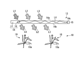
- FIG. 3 is a schematic diagram of the daylighting units 13a, 13b, 13c, and 13d of the first embodiment.
- Each of the daylighting units 13a, 13b, 13c, and 13d includes a light guide body 14 (also referred to as a fluorescent light guide body) and a solar cell element 15 that receives the light L4 collected on the end surface of the light guide body 14. I have.
- the plate-like portions of the daylighting portions 13a, 13b, 13c, and 13d are configured by the light guide 14, and the solar cell element 15 is provided on the end surface.
- the sheet 102a is similarly configured to include the light guide 14 and the solar cell element 15, but the resin sheet itself becomes the light guide 14. That is, the resin sheet itself includes the phosphor 16 and guides the fluorescence to the solar cell element 15 provided at the end of the resin sheet. In the sheet 102a, the solar cell element 15 is provided at the top of the greenhouse 100a.
- the light guide 14 is a substantially rectangular plate-like member having a first main surface 114a, a second main surface 114b, and an eleventh end surface 114c.
- the light guide 14 has a phosphor 16 dispersed in a base material (transparent light guide) 17 made of a highly transparent organic material or inorganic material that does not contain a phosphor such as acrylic resin, polycarbonate resin, or glass. It is a thing.
- the phosphor in the light guide plate 14 absorbs light in a predetermined wavelength band and emits fluorescence in a wavelength band different from the absorbed wavelength band.
- the phosphor 16 that does not absorb the light L3 having a wavelength that contributes to the photosynthesis of the plant 19 or a wavelength having a large contribution or that emits light L4 having a wavelength that contributes to the photosynthesis of the plant 19 or a wavelength having a large contribution is used. It is done. For example, it is preferable that the peak wavelength of the absorption spectrum of the phosphor 16 and the peak wavelength of the absorption spectrum of the photosynthetic pigment 19a of the plant 19 are different.
- the phosphor 16 preferably emits light L4 corresponding to the peak wavelength of the absorption spectrum of the photosynthetic pigment 19a of the plant 19. Thereby, light L3, L4 of the wavelength which contributes to the photosynthesis of the plant 19 or a wavelength with a large contribution can be sufficiently supplied into the plant cultivation room 10.
- the light guide 14 absorbs a part L1 of the external light incident from the first main surface 114a by the phosphor 16, and a part of the light L4 emitted from the phosphor 16 from the second main surface 114b to the plant cultivation room. Inject into 10 rooms. The light L4 emitted into the room of the plant cultivation room 10 is absorbed by the photosynthetic pigment 19a of the plant 19 and used for cultivation of the plant 19.
- the remaining part of the light L4 emitted from the phosphor 16 propagates toward the first end face 114c while being totally reflected inside the light guide 14 (totally reflected at the interface between the light guide 14 and the outside air). To do.
- the light L4 propagated toward the first end face 114c is collected on the first end face 114c, received by the solar cell element 15, and used for power generation.
- Part of the external light L2 and L3 that has not been absorbed by the phosphor 16 passes through the light guide 14 and is emitted into the plant cultivation room 10.
- a part L3 of the light L2 and L3 transmitted through the light guide body 14 is absorbed by the photosynthetic pigment 19a of the plant 19 together with the light L4 emitted from the phosphor 16, and is used for cultivation of the plant 19.
- the phosphor 16 is described as being uniformly distributed in the light guide 14, but a film containing the phosphor is sandwiched between two light guide plates not containing the phosphor.
- the light guide 14 may be configured.
- the solar cell element 15 an element which shows the maximum conversion efficiency at the peak wavelength of the emission spectrum of the phosphor 16 is used.
- known solar cells such as silicon solar cells, compound solar cells, and organic solar cells can be suitably used. Many of these solar cells can realize high conversion efficiency only in a narrow wavelength range.
- the light L4 incident on the solar cell element 15 is light in a narrow wavelength range radiated from the phosphor 16, if the solar cell element 15 suitable for the phosphor 16 is selected, the light L4 is incident on the solar cell element 15.
- the converted light L4 can be converted into electric energy with high conversion efficiency.
- FIG. 4 is an enlarged view of the daylighting unit 13a and its periphery.
- the daylighting unit 13a includes the light guide 14a and the solar cell element 15a as described above.
- the lighting part 13a can be opened and closed by moving the lower end part up and down by the opening and closing mechanism 112a.
- the roof 11 is also comprised including the light guide 211b and the solar cell element 212b as mentioned above.
- a light shielding device 109 that can shield light that passes through the roof 11 and enters the plant cultivation apparatus 1 is provided inside the roof 11.
- the light shielding device 109 includes a storage unit 21, a light shielding sheet 22, a string 23, and a rotating shaft 24.
- a storage unit 21 that is provided at the top of the roof 11 and stores the light shielding sheet 22, a light shielding sheet 22 that is spread so as to cover the inside of the roof 3 and shields light entering the plant cultivation apparatus 1, and a storage unit
- the light shielding sheet 22 in 21 is configured to include a string 23 that pulls the light shielding sheet 22 and a rotating shaft 24 that pulls the string 23 by winding the light so that the light shielding sheet 22 extends so as to cover the inside of the roof 3.
- FIG. 5 is a diagram showing the spectrum distribution of sunlight on the ground.
- the horizontal axis is the wavelength of sunlight
- the vertical axis is the intensity.
- the intensity on the vertical axis is a value normalized so that the maximum value is 1.
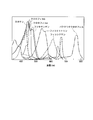
- FIG. 6 is a diagram showing absorption spectra of various photosynthetic pigments.
- the horizontal axis represents the wavelength of light to be absorbed
- the vertical axis represents the absorption intensity.
- FIG. 7 is a diagram showing an absorption spectrum and an emission spectrum when a BASF Lumogen F Yellow TM 170 (trade name) is used as a phosphor.
- the horizontal axis represents the wavelength of light to be absorbed
- the vertical axis represents the absorption intensity.
- the intensity on the vertical axis is a value normalized so that the maximum value is 1.
- the dotted line indicates the absorption spectrum
- the solid line indicates the emission spectrum.
- FIG. 8 is a diagram showing an absorption spectrum and an emission spectrum when BASF Lumogen F Red 305 (trade name) is used as the phosphor.
- the horizontal axis represents the wavelength of light to be absorbed
- the vertical axis represents the absorption intensity.
- the intensity on the vertical axis is a value normalized so that the maximum value is 1.
- a dotted line shows an absorption spectrum and a solid line shows an emission spectrum.
- the photosynthetic pigment has a characteristic absorption spectrum.
- sunlight includes light in a wide wavelength range from ultraviolet light to infrared light.
- a photosynthesis dye light of a specific wavelength is absorbed among these lights, and photosynthesis is performed. Used.
- the peak wavelength of the absorption spectrum differs for each photosynthetic pigment.
- chlorophyll a has peak wavelengths near 435 nm and 680 nm.
- Chlorophyll b has peak wavelengths around 450 nm and 650 nm.
- Caroten and fucoxanthin have a peak wavelength around 450 nm.
- Phycoerythrin has a peak wavelength around 550 nm.
- Phycocyanin has a peak wavelength around 610 nm.
- Bacteriochlorophyll has a peak wavelength around 770 nm.
- the phosphor 16 used for the light guide 14 absorbs light having a wavelength shorter than 550 nm and has a wavelength of around 550 nm.
- a phosphor that emits light of a wavelength is preferred.
- the phosphor Lumogen F Yellow® 170 (trade name) in FIG. 7 has absorption spectrum peak wavelengths near 450 nm and 470 nm, and emission spectrum peak wavelengths near 480 nm and 520 nm. Therefore, if the phosphor Lumogen F Yellow 170 (trade name) in FIG.
- light having a wavelength that does not contribute to the photosynthesis of phycoerythrin or a wavelength with a small contribution is converted into light having a wavelength that contributes to the photosynthesis of phycoerythrin or a light with a large contribution.
- light having a wavelength that contributes to the photosynthesis of phycoerythrin or a wavelength that has a large contribution among the sunlight incident on the light guide 14 can be transmitted as it is into the plant cultivation room 10 without being absorbed by the phosphor 16.
- Lumogen F Yellow 170 (trade name) has an absorption spectrum and an issuance spectrum as described above, and absorbs light in the blue wavelength band and emits fluorescence in the green wavelength band.
- the light guide 14 is irradiated with the light Bi of the blue wavelength band, the light Gi of the green wavelength band, and the light Ri of the red wavelength band, the light Bi is guided to a large part. Instead of being transmitted through the light body 14, it is absorbed by the phosphor 16.
- the light Bo transmitted without being reflected at the interface of the light guide 14 irradiates a plant or the like cultivated in the plant cultivation room 10.
- the light Gi and the light Ri are transmitted as they are to irradiate the plants cultivated in the plant cultivation room 10 as the light Go in the green wavelength band and the light Ro in the red wavelength band.
- the phosphor 16 used for the light guide 14 absorbs light having a wavelength shorter than 610 nm and is around 610 nm.
- a phosphor that emits light of a wavelength is preferred.
- the phosphor Lumogen F Red 305 (trade name) in FIG. 8 has an absorption spectrum peak wavelength around 450 nm and 580 nm, and an emission spectrum peak wavelength around 610 nm. Therefore, if the phosphor Lumogen F Red 305 (trade name) in FIG.
- the light having a wavelength that does not contribute to the photosynthesis of phycocyanin or a light having a small contribution is converted into light having a wavelength that contributes to the photosynthesis of phycocyanin or a wavelength having a large contribution.
- the light that has a wavelength that contributes to the photosynthesis of phycocyanin or a wavelength that contributes greatly to the photosynthesis of the sunlight incident on the light guide 14 can be directly supplied to the plant cultivation room 101 without being absorbed by the phosphor 16. It can penetrate into the chamber 10.
- the absorption spectrum and emission spectrum of the phosphor 16 applied to the light guide 14 are suitable for cultivation of the plant 19. Therefore, it is possible to cultivate the plant 19 and generate power using the outside light efficiently.
- FIG. 10 is a schematic diagram of the daylighting unit 20 of the second embodiment.
- the configuration other than the light guide 21 is the same as the daylighting unit 13 of the first embodiment. Therefore, only the configuration of the light guide 21 will be described here.
- symbol is attached
- the light guide 21 includes a transparent light guide 22, a phosphor layer 23, and a transparent protective film (transparent member) 24.
- the phosphor layer 23 is provided on the main surface 22 a of the transparent light guide 22, and the transparent protective film 24 is provided on the phosphor layer 23.
- the main surface of the transparent protective film 24 on the outside light incident side is the first main surface 21 a of the light guide 21, and the main surface of the transparent light guide 22 opposite to the outside light incident side is the first surface of the light guide 21. 2 is a main surface 21b.
- the end surfaces of the transparent light guide 22, the transparent protective film 24, and the phosphor layer 23 facing the solar cell elements 15 are the first end surface 21 c of the light guide 21.
- the phosphor layer 23 may be one in which the phosphor 16 is dispersed inside the transparent film 25.
- the phosphor layer 23 has the phosphor 16 dispersed in a transparent resin 25 that bonds the transparent light guide 22 and the transparent protective film 24 laminated on the main surface 22 a of the transparent light guide 22. It may be a thing.
- a highly transparent organic material or inorganic material that does not contain a phosphor such as acrylic resin, polycarbonate resin, or glass is used.
- a portion L1 of the external light that has passed through the transparent protective film 24 and entered the phosphor layer 23 is converted into fluorescence L4 and emitted toward the transparent light guide 22 and the transparent protective film 24.
- a part of the light L4 emitted from the phosphor layer 23 propagates toward the first end face 21c while totally reflecting the inside of the transparent light guide 22 and the transparent protective film 24.
- the light condensed on the first end face 21c enters the solar cell element 15 and is used for power generation.
- the remaining part of the light L4 radiated toward the transparent light guide 22 is emitted from the second main surface 21b into the plant cultivation room 10.
- the light L4 emitted into the room of the plant cultivation room 10 is absorbed by the photosynthetic pigment 19a of the plant 19 and used for cultivation of the plant 19.
- Part of the external light L2 and L3 that has not been absorbed by the phosphor 16 passes through the light guide 21 and is emitted into the plant cultivation room 10.
- a part L3 of the light L2 and L3 transmitted through the light guide 21 is absorbed by the photosynthetic pigment 19a of the plant 19 together with the light L4 emitted from the phosphor 16, and is used for cultivation of the plant 19.
- the light guide 21 is composed of a plurality of members including a transparent light guide 22 and a phosphor layer 23. Therefore, when the phosphor layer 23 deteriorates, only the phosphor layer 23 can be separated from the transparent light guide 22 and replaced. Therefore, the maintenance cost can be reduced as compared with the case where the entire light guide 21 is replaced.
- the light emitted from the phosphor is directly incident on the solar cell element.
- the light emitted from the phosphor is incident on the inside of the light guide or between the light guide and the solar cell element. It may be made to enter into a solar cell element, after converting into other wavelengths by the wavelength conversion member arranged in.
- “the light condensed on the first end face” received by the solar cell element is not only the light emitted from the phosphor, but also the light obtained by converting the light emitted from the phosphor into another wavelength. Is included.
- the power generation efficiency of the solar cell element is increased.
- the type of the solar cell element can be selected regardless of the type of phosphor (the type of plant photosynthetic pigment), the range of selection of the solar cell element is widened.
- FIG. 11 is a schematic block diagram showing the configuration of the cultivation management system in the present embodiment.
- a cultivation management system 2100 includes a commercial power supply 2101, a power receiving board 2102, a power conditioner 2103, a secondary battery 2104, a thermometer 2105, a cultivation management device 2106, a solar power generation device 2107, a light control device 2108, and an air conditioner 2111.
- an opening / closing mechanism 2112 is included.
- the cultivation management device 2106 acquires information indicating the power generated by the solar power generation device 2107 from the solar power generation device 2107.
- the solar power generation device 2107 is a solar power generation device that constitutes the daylighting units 13 a, 13 b, 13 c, and 13 d and the roof 11. Moreover, the cultivation management apparatus 2106 is installed in the plant cultivation apparatus 1 (greenhouse), and acquires the measurement result of the thermometer 2105 that measures the temperature in the plant cultivation apparatus 1. The cultivation management device 2106 is based on the information indicating the power and the measurement result of the thermometer 2105, and the opening / closing mechanism of the light control device 2120, the air conditioner 2111, and the daylighting units 13a, 13b, 13c, and 13d of the plant cultivation device 1. 2112 is controlled.
- the light control device 2108 includes the light shielding device 109 shown in FIG. 3 and the illumination device 110 provided in the plant cultivation device 1.
- the light shielding device 109 has the configuration shown in FIG.
- the air conditioner 2111 is an air conditioner that controls the temperature in the plant cultivation apparatus 1 and can operate as cooling to lower the temperature or operate as heating to increase the temperature.
- the opening / closing mechanism 2112 opens each of the daylighting units 13a, 13b, 13c, and 13d so that the outside air can be taken into the plant cultivation apparatus 1 or closed so that the outside air does not enter the plant cultivation apparatus 1. can do.
- the illuminating device 2110 is an illuminating device such as an LED (Light Emitting Diode) that is installed in the plant cultivating apparatus 1 and irradiates light to the plant being cultivated.
- the power conditioner 2103 converts the electric power generated by the solar power generation device 2108 and the electric power stored in the secondary battery 2104 into alternating current, and the light control device 2120 and the air conditioner via the power receiving panel 2102 2111, an opening / closing mechanism 2112, and a cultivation management apparatus 2106 are supplied as electric power for operating each apparatus.
- the power conditioner 2103 uses the difference power to recharge the secondary battery 2104.
- the power receiving board 2102 supplies the power supplied from the power conditioner 2103 to the light control device 2120, the air conditioner 2111, the opening / closing mechanism 2112, and the cultivation management device 2106.
- the power from the commercial power supply 2101 supplied by the power company or the like is also used.
- FIG. 12 is a schematic block diagram showing the configuration of the cultivation management device 2106.
- the cultivation management device 2106 includes a temperature management unit 2201, a temperature pattern storage unit 2202, an open / close state control unit 2203, an air conditioner control unit 2204, a solar radiation amount detection unit 2205, a power generation device integrated solar radiation amount calculation unit 2206, and a power generation device integrated solar radiation amount storage.
- a unit 2207, a greenhouse integrated solar radiation amount calculation unit 2208, a greenhouse integrated solar radiation amount storage unit 2209, a dimming control unit 2210, and a target integrated solar radiation amount storage unit 2211 are configured.
- the temperature management unit 2201 compares the measurement result of the thermometer 2105 with the target temperature at the time indicated by the temperature pattern read from the temperature pattern storage unit 2202. When the difference between these two values exceeds a predetermined range, the temperature management unit 2201 instructs the open / close state control unit 2203 and the air conditioner control unit 2204 so as to be within the predetermined range. For example, when the measurement result is larger than the target temperature by a predetermined threshold value ⁇ and each of the daylighting units 13a, 13b, 13c, and 13d is opened, the daylighting units 13a, 13b are opened with respect to the open / close state control unit 2203. , 13c, and 13d are instructed to close, and the air conditioner control unit 2204 is instructed to set the target temperature to the air conditioner 2111. Further, when the measurement result is larger than the target temperature by a predetermined threshold value ⁇ and each of the daylighting units 13a, 13b, 13c, and 13d is closed, the daylighting units 13a, 13b, Instruct to open 13c and 13d.
- the daylighting units 13a, 13b, 13c, and 13d are opened.
- the daylighting units 13a, 13b are opened with respect to the open / close state control unit 2203.
- 13c, and 13d are instructed to close.
- the air conditioner control unit 2204 sends the above-described target temperature to the air conditioner 2111. Instruct to set.
- the temperature pattern storage unit 2202 stores a temperature pattern indicating the target temperature at each time according to the plant being cultivated. This temperature pattern may be a pattern according to the number of days from the start of cultivation or the date.
- the open / close state control unit 2203 generates a signal instructing the open / close mechanism 2112 to open / close the daylighting units 13a, 13b, 13c, and 13d in accordance with an instruction from the temperature management unit 2201.
- the air conditioner control unit 2204 generates an operation start / stop instruction or a target temperature setting instruction signal for the air conditioner 2111 in accordance with the instruction from the temperature management unit 2201.
- the solar radiation amount detection unit 2205 first acquires the degree of deterioration of the solar power generation device 2107 based on the cumulative solar radiation amount stored in the power generation device integrated solar radiation amount storage unit 2207. Then, the amount of solar radiation is acquired by adding the degree of deterioration to the value indicating the power generated by the solar power generation device 2107.
- the degree of deterioration for example, the correspondence between the amount of integrated solar radiation and a coefficient representing the degree of deterioration is stored in advance, and this corresponds to the amount of integrated solar radiation stored in the power generation device integrated solar radiation amount storage unit 2207. There is a method of reading a coefficient.
- the coefficient representing the degree of deterioration is the ratio of the power to be generated and the power to be generated when it is not deteriorated. If it is 90% when the power to be generated is not deteriorated, it is “0.9”. is there. Since the light guide body 14 and the solar cell element 15 are deteriorated by the irradiated ultraviolet rays, the degree of deterioration can be obtained as a value corresponding to the integrated solar radiation amount.
- correspondence between the power generated by the solar power generation device 2107 and the amount of solar radiation is stored in advance, and the power generated by the solar power generation device 2107 corresponds to the integrated solar radiation amount.
- the power generation device integrated solar radiation amount calculation unit 2206 updates the integrated solar radiation amount related to the solar power generation device 2107 stored in the power generation device integrated solar radiation amount storage unit 2207 using the solar radiation amount calculated by the solar radiation amount detection unit 2205.
- the integrated solar radiation amount storage unit 2209 stores the integrated solar radiation amount calculation unit 2208 in the greenhouse using the solar radiation amount calculated by the solar radiation amount detection unit 2205 and the control result of the dimming device 2108 by the dimming control unit 2210.
- the accumulated solar radiation amount in the plant cultivation apparatus 1 to be updated is updated.
- the integrated solar radiation amount calculation unit 2208 in the greenhouse is controlled by the solar radiation amount detection unit 2205.
- a value obtained by subtracting the decrease due to the shielding from the calculated amount of solar radiation is regarded as the amount of solar radiation for the time period, and is added to the cumulative amount of solar radiation stored in the integrated solar radiation amount storage unit 2209 in the greenhouse.
- the integrated solar radiation amount calculation unit 2208 in the greenhouse uses the lighting device 2110 to calculate the solar radiation amount calculated by the solar radiation amount detection unit 2205.
- a value obtained by adding the amount of solar radiation is regarded as the amount of solar radiation for the time period, and is added to the cumulative amount of solar radiation stored in the integrated solar radiation amount storage unit 2209 in the greenhouse.
- the dimming control unit 2210 calculates the target integrated solar radiation amount at the current time among the integrated solar radiation amount stored in the greenhouse integrated solar radiation amount storage unit 2209 and the target integrated solar radiation amount stored in the target integrated solar radiation amount storage unit 2211. Compare The dimmer 2108 is controlled according to the result of this comparison and the amount of solar radiation calculated by the solar radiation amount detection unit 2205. For example, as a result of the comparison, when the integrated solar radiation amount is smaller than the target integrated solar radiation amount by a predetermined threshold A or more and the solar radiation amount has not reached the predetermined threshold B, the lighting device 2110 is turned on.
- the light shielding device 2109 blocks light.
- the target integrated solar radiation amount storage unit 2211 stores the cultivation elapsed time and the target integrated solar radiation amount in association with each other. Cultivation elapsed time is the elapsed time from the start of cultivation.
- the dimming control unit 2210 stores information indicating the date and time when cultivation is started, and calculates the cultivation elapsed time from this information and the current time.
- FIG. 13 is a flowchart for explaining the operation of the cultivation management system 2100 in the present embodiment.
- the cultivation management device 2106 stores a temperature pattern and a target integrated solar radiation amount according to a plant cultivated by the plant cultivation device 1 by a user operation. The time interval for monitoring temperature and solar radiation is also set.
- the solar radiation amount detection unit 2205 acquires a value indicating the electric power generated from the solar power generation device 2107, and calculates the solar radiation amount based on this value.
- the power generation device integrated solar radiation amount calculation unit 2206 updates the power generation device integrated solar radiation amount storage unit 2207
- the greenhouse integrated solar radiation amount calculation unit 2208 updates the greenhouse internal solar radiation amount storage unit 2209.
- the temperature management part 2201 acquires the temperature in the plant cultivation apparatus 1 which the thermometer 2105 measures.
- step S3 the dimming control unit 2210 determines whether the integrated solar radiation amount in the plant cultivation device 1 is within an appropriate range, and the temperature management unit 2210 has an appropriate temperature in the plant cultivation device 1. Determine if it is within range. If it is determined that it is within the appropriate range (S3-Yes), the process returns to step S2, and the process is repeated when the set time interval has elapsed. If it is determined in step S3 that it is not within the appropriate range (S3-No), the process proceeds to step S4. When the integrated solar radiation amount is outside the set range (S4-Yes), the process proceeds to step S6 through step S5 for controlling the solar radiation amount. When the cumulative solar radiation amount is not outside the set range (S4-No), the process proceeds to step S6. Transition to.
- step S6-Yes When the temperature in the plant cultivation apparatus 1 is outside the set range (S6-Yes), the process returns to step S2 through step S7 for controlling the temperature, and when not outside the set range (S6-No), The process returns to step S2 as it is, and the processing is repeated when the set time interval has elapsed. Details of the processes in steps S5 and S7 will be described later.
- FIG. 14 is a flowchart for explaining the process A of step S5 of FIG.
- the dimming control unit 2210 determines whether or not the integrated solar radiation amount is less than the set range (Sa1). When it is determined that it is less than the set range (Sa1-Yes), the process proceeds to step Sa3, the lighting device 2110 is turned on, and the process A is terminated. On the other hand, when it is determined that it is larger than the set range (Sa1-No), the process proceeds to step Sa2, the light shielding device 2109 is expanded, and the process A is terminated.
- FIG. 15 is a flowchart for explaining the process B of step S5 of FIG.
- the temperature management unit 2201 determines whether or not the temperature in the plant cultivation apparatus 1 is lower than the set range (Sb1). When it is determined that it is lower than the set range (Sb1-Yes), it is further determined whether or not the daylighting units 13a, 13b, 13c, and 13d are open (Sb2). When it is determined that the daylighting units 13a, 13b, 13c, and 13d are open (Sb2-Yes), the open / close state control unit 2203 is instructed to close the daylighting units 13a, 13b, 13c, and 13d.
- the temperature management unit 2201 determines whether or not the temperature is within the set range after a predetermined time has elapsed (Sb8). When it is within the set range (Sb8-Yes), the process B is terminated, and when it is not within the set range (Sb8-No), the process returns to step Sb1 to repeat the process.
- step Sb2 when it is determined in step Sb2 that the daylighting units 13a, 13b, 13c, and 13d are not opened (Sb2-No), the temperature management unit 2201 sets the target temperature in the air conditioner 111 and operates it. Thus, the air conditioner control unit 2204 is instructed (Sb4), and then the process proceeds to the above-described step Sb8.
- step Sb1 When it is determined in step Sb1 that the temperature is not lower than the set range (Sb1-No), it is further determined whether or not the daylighting units 13a, 13b, 13c, and 13d are open (Sb5).
- step Sb5 When it is determined that these lighting units are open (Sb5-Yes), the open / close state control unit 2203 is instructed to close the lighting units 13a, 13b, 13c, and 13d (Sb6), and the process proceeds to step Sb4. . If it is determined in step Sb5 that the daylighting unit has not been opened (Sb5-No), the opening / closing state control unit 2203 is instructed to open the daylighting units 13a, 13b, 13c, and 13d (Sb7). Transition to Sb8.
- the solar radiation amount is calculated based on the electric power generated by the solar power generation device 2107, the solar radiation amount can be managed without providing a solar radiation meter. Further, since the accumulated amount of solar radiation is stored, the degree of deterioration of the photovoltaic power generation apparatus 2107 is acquired based on this, and used for calculation of the amount of solar radiation, the amount of solar radiation can be managed more accurately. Further, in the solar power generation device 2107, the solar cell element 15 generates power by the fluorescence emitted from the phosphor 16 in the light guide body 14. Therefore, whether it is direct light from the sun or scattered light scattered by dust in the air, the phosphor 16 in the light guide 14 is converted into fluorescence and used for power generation. That is, by calculating the amount of solar radiation based on the electric power generated by the solar power generation device 2107, the amount of solar radiation that combines the direct light from the sun and the scattered light can be calculated.
- FIG. 16 is a schematic block diagram showing the configuration of the cultivation management system in the present embodiment.
- the cultivation management system 2100a in the present embodiment has the same configuration as the cultivation management system 2100 in FIG. 11, but includes a cultivation management apparatus 2106a instead of the cultivation management apparatus 2106, and the cultivation management apparatus 2106a via the communication network 2113a. The difference is that a setting terminal 2114a is connected.
- the cultivation management device 2106a is the same device as the cultivation management device 2106, except that, for example, the setting in step S1 in FIG. 13 can be performed from the setting terminal 2114a.
- the communication network 2113a is a network such as the Internet or a mobile phone network, and mediates communication between the setting terminal 2114a and the cultivation management device 2106a.
- the setting terminal 2114a is a personal computer, a mobile phone, or the like. As described above, the setting terminal 2114a performs setting to the cultivation management device 2106a, and acquires and displays the control status of each device by the cultivation management device 2106a. Can do.
- the cultivation management system 2100a in the present embodiment can obtain the same effects as the cultivation management system 2100 in the first embodiment. Further. Thus, since the setting terminal 2114a is provided, the state of the plant cultivation apparatus 1 can be managed even from a place away from the plant cultivation apparatus 1.
- the daylighting unit may be provided in a portion other than 13a, 13b, 13c, and 13d.
- the target value of the integrated solar radiation amount stored in the target integrated solar radiation amount storage unit 2211 is used to control the light control device 2108.
- the target value of the solar radiation amount at each time may be stored, and the dimmer 108 may be controlled by comparing the target value with the solar radiation amount calculated by the solar radiation amount detection unit 2205.
- the photovoltaic power generation apparatus 2107 generates power based on thresholds ⁇ and ⁇ for determining whether or not to operate the air conditioner 2111 and thresholds A and B for determining whether or not the lighting apparatus 2110 is turned on. You may make it change according to the electric power which is. For example, when the generated power is sufficiently large, the threshold values ⁇ , ⁇ , A, and B are set to smaller values. As a result, when the power being generated is sufficiently large, it is possible to maintain a state close to the target integrated solar radiation amount and temperature. That is, it is possible to trade off the use of power from the commercial power source 2101 and the cultivation environment.
- the open / close state control unit 2203 acquires a value indicating the power generated by the solar power generation device 2107 when the lighting units 13a, 13b, 13c, and 13d are opened, for each lighting unit.
- the power indicated by this value may be opened to the maximum position. That is, you may make it determine the opening / closing state of the lighting parts 13a, 13b, 13c, and 13d based on the room temperature in the plant cultivation apparatus 1, and the information which shows the electric power which the solar power generation device 2107 is generating. . Thereby, more electric power can be generated.
- achieving the function of the cultivation management apparatus 2106 in FIG. 11 and the cultivation management apparatus 106a in FIG. 16 is recorded on a computer-readable recording medium, and the program recorded on this recording medium is stored in a computer system. You may implement
- the “computer system” includes an OS and hardware such as peripheral devices.
- the greenhouse design and sales system of the present embodiment is a system for performing design and sales of the plant cultivation apparatus 1 described above.
- the plant cultivation apparatus 1 may be called the greenhouse 1.
- FIG. 17 is a schematic block diagram showing the configuration of the greenhouse design and sales system in the present embodiment.
- the greenhouse design and sales system 3200 in the present embodiment includes a plurality of user terminals 3201, a network 3202, a greenhouse design device 3203, and a delivery instruction device 3204.
- the greenhouse design apparatus 3203 includes a communication interface unit 3211, a solar cell selection unit 3212, a solar cell storage unit 3213, a structure selection unit 3214, a member storage unit 3215, an ordering unit 3216, and an order management unit 3217.
- the solar cell selection unit 3212 and the solar cell storage unit 3213 constitute a solar power generation device design apparatus 3220.
- the user terminal 3201 is owned by each of the users A1 to An who purchase the greenhouse 1 (plant cultivation apparatus 1).
- a user terminal 3201 is a personal computer used by each user, and is connected to a network 3202.
- the network 3202 is a communication network such as the Internet, and mediates communication between the user terminal 3201, the greenhouse design device 3203, and the delivery instruction device 3204.
- Greenhouse design apparatus 3203 and delivery instruction apparatus 3204 are owned by greenhouse distributor B.
- the greenhouse design device 3203 uses the user terminal 3201 to select a member for constructing the greenhouse 1 based on conditions specified by the user, and notifies the delivery instruction device 3204 of the selected member and its delivery destination.
- the delivery instruction device 3204 outputs a delivery instruction of the member notified from the greenhouse design device 3203 to the notified delivery destination.
- the greenhouse dealer B wholesales the corresponding member from the stock and delivers it to the delivery destination. If there is no stock, the corresponding member may be manufactured and delivered.
- the communication interface unit 3211 of the greenhouse design device 3203 includes a function for realizing a communication protocol such as a LAN (Local Area Network) card connected to the network 3202 or the Internet Protocol. Each unit of the greenhouse design device 3203 communicates with an external device via the communication interface unit 3211.
- the solar cell selection unit 3212 specifies phosphors and solar cells to be used for the greenhouse 1 based on information indicating the plant designated by the user and notified from the user terminal 3201 and information stored in the solar cell storage unit 3213. select.
- the solar cell storage unit 3213 stores information indicating the type of plant, information indicating the type of phosphor, and information indicating the type of solar cell element in association with each other.
- the structure selection unit 3214 is information that indicates the type and size (width, depth, etc.) of the greenhouse 1 specified by the user and notified from the user terminal 3201, and the phosphor and solar cell element selected by the solar cell selection unit 3212. Based on the information stored in the member storage unit 3215, the member used for the greenhouse 1 and the amount thereof are selected. Furthermore, the structure selection unit 3214 calculates the total sales amount according to the selected member and quantity, and notifies the user terminal 3201 of the total.
- the type of the greenhouse 1 is information for identifying whether it is a building type as shown in FIG. 1 or a greenhouse type as shown in FIG.
- the member storage unit 3215 stores information indicating each member for building the greenhouse 1, information indicating the size, and information indicating the price in association with each other.
- the ordering unit 3216 stores the delivery destination designated by the user and notified from the user terminal 3201, the member and quantity selected by the structure selection unit 3214, and information for identifying the user in the order management unit 3217, and the delivery. This information is notified to the instruction device 3204.
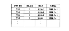
- FIG. 18 is a diagram illustrating an example of information stored in the solar cell storage unit.
- the solar cell storage unit 3213 corresponds to the plant type “crop A”, the priority “1”, the phosphor “phosphor a1”, and the solar cell element “solar cell ⁇ 1”.
- the plant type “crop A”, the priority “2”, the phosphor “phosphor a1”, and the solar cell element “solar cell ⁇ 2” are stored in association with each other, and the plant type “ “Crop A”, priority “3”, phosphor “phosphor a2”, and solar cell element “solar cell ⁇ 3” are stored in association with each other, plant type “crop B”, and priority “1”.
- the phosphor“ phosphor b ”, and the solar cell element“ solar cell ⁇ ” are stored in association with each other, and so on.
- Information indicating the type and information indicating the type of the solar cell element are stored in association with each other.
- the combination of “phosphor a1” and “solar cell ⁇ 1” and the combination of “phosphor a1” and “solar cell ⁇ 2” are stored in association with “crop A”.
- a combination of a plurality of phosphors and solar cell elements may be stored for the same plant type. At this time, the priorities in this combination are stored as “1” and “2”. Note that the smaller the value of this priority is, the higher the priority is.
- Crop A” and “Crop B” are names of crops such as spinach and tomato, for example. Further, “phosphor a1”, “phosphor a2”, “phosphor b” and the like are names of phosphors such as LUMOGEN (registered trademark) F Yellow 170 and LUMOGEN (registered trademark) F Red 305, for example. .
- “solar cell ⁇ 1”, “solar cell ⁇ 2”, “solar cell ⁇ 3”, “solar cell ⁇ ”, and the like include, for example, InGaP (indium gallium phosphorus), InGaAs (indium gallium arsenide), AlGaAs ( Aluminum, gallium, arsenic), Cu (In, Ga) Se2 (copper (indium gallium) selenium 2), Cu (In, Ga) (Se, S) 2 (copper (indium gallium) (selenium, sulfur) 2 , CuInS2 (copper / indium / sulfur 2), CdTe (cadmium / tellurium), CdS (cadmium / sulfur), etc., Si (silicon) based compound solar cells, Si, InGaAs and other quantum dot solar cell names The name is the name of the organic solar cell.
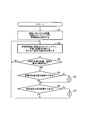
- FIG. 19 is a flowchart for explaining the operation of the greenhouse design and sales system in the present embodiment.
- the solar cell selection unit 3212 acquires the type of plant to be cultivated input by user operation in the user terminal 3201 via the network 3202 (S31).
- the solar cell selection unit 3212 refers to the solar cell storage unit 3213 and selects a phosphor and a solar cell element according to the type of plant to be cultivated (S32).
- the solar cell selection part 3212 selects the thing with high priority, when the solar cell memory
- a combination of a phosphor and a solar cell element that are stored in association with each other is selected.
- the structure selection unit 3214 acquires the type and dimensions of the greenhouse 1 input by the user operation to the user terminal 3201 via the network 3202 (S33).
- the structure selection unit 3214 stores the greenhouse 1 in the greenhouse 1 based on the acquired type and size of the greenhouse 1, the phosphor and solar cell element selected by the solar cell selection unit 3212, and the information stored in the member storage unit 3215. A member to be used and its amount are selected (S34).
- the ordering unit 3216 acquires the delivery destination input by the user operation in the user terminal 3201 via the network 3202 (S35).
- the ordering unit 3216 stores the acquired delivery destination, the member and quantity selected by the structure selection unit 3214, and information for identifying the user in the order management unit 3217, and notifies the delivery instruction apparatus 3204 of the information. Then, an ordering instruction is given (S36).
- the delivery instruction apparatus 3204 outputs a delivery instruction based on the member, amount, and delivery destination notified from the ordering unit 3216 (S37), and ends the process.
- Greenhouse dealer B wholesales the corresponding member from the stock and delivers it to the delivery destination (user) in accordance with the delivery instruction output in step S37.
- the solar cell storage unit 3213 stores the name of the plant to be cultivated and the fluorescence that emits fluorescence mainly by absorbing a wavelength band different from the wavelength band that the plant uses for photosynthesis. It is the name of the body and the name of the solar cell element with good power generation efficiency in the fluorescence wavelength band. Furthermore, the wavelength band of the fluorescence emitted by the phosphor of the name stored in the solar cell storage unit 213 is the wavelength band used for photosynthesis by the plant of the name stored in association with the name of this phosphor. It is desirable. As described above, FIG. 5 is a graph showing the spectrum distribution of sunlight on the ground. As shown in FIG. 5, sunlight is distributed from 300 nm to 1100 nm or more, and has a maximum intensity in the vicinity of 500 nm.
- FIG. 6 is a graph showing the absorption spectrum distribution of the photosynthetic pigment.
- the wavelength range of the absorption spectrum of the sunlight spectrum is different.
- carotene absorbs light from about 400 nm to about 500 nm and has a peak around 450 nm.
- Chlorophyll a absorbs a wide range of about 400 nm to about 670 nm, but mainly absorbs about 430 nm to about 470 nm and around 650 nm.
- Chlorophyll b absorbs a wide range from about 400 nm to about 700 nm, but mainly absorbs from about 400 nm to about 450 nm and around 670 nm.
- Fucoxanthin absorbs light from about 400 nm to about 500 nm and has a peak around 450 nm.
- Phycoerythrin absorbs light from about 500 nm to about 570 nm and has a peak around 530 nm.
- Phycocyanin absorbs light from about 550 nm to about 650 nm and has a peak near 610 nm.
- Bacteriochlorophyll absorbs over the entire wavelength range, but mainly absorbs at 400 nm or less, from about 750 nm to about 800 nm, and has a peak near 760 nm.
- FIG. 8 is a graph showing the absorption and emission spectrum distribution of LUMOGEN (registered trademark) F Red 305, which is an example of a phosphor.
- the dotted line is an absorption spectrum
- the solid line is an emission spectrum.
- LUMOGEN (registered trademark) F Red 305 mainly absorbs light of 550 nm to 600 nm, and its absorption spectrum has a peak of about 578 nm. Further, light of 600 to 670 nm is emitted, and the peak of the emission spectrum is about 612 nm.
- Sunlight that has passed through the light guide 14 added with LUMOGEN (registered trademark) F Red 305 shown in FIG. 8 as a phosphor is absorbed from 550 nm to 600 nm and greatly reduced in intensity, but for other wavelength bands The rate of transmission without being absorbed is high. Therefore, in the case of a plant having carotene, chlorophyll a, chlorophyll b, or the like as a photosynthetic pigment, light in a wavelength band for photosynthesis is irradiated through the light guide 14.
- LUMOGEN registered trademark
- the solar cell storage unit 3213 stores information indicating the type of plant (for example, the name of the plant) and information indicating the photosynthetic pigment used by the plant for photosynthesis in association with each other, and further sets the type of phosphor.
- the information shown, the wavelength band that this phosphor mainly absorbs, and the information that shows the photosynthetic dye that mainly absorbs a wavelength band different from the wavelength band that this phosphor mainly absorbs are stored in association with each other. Also good.
- the solar cell storage unit 3213 associates the name of the plant to be cultivated with the name of the phosphor that mainly absorbs the wavelength band different from the wavelength band used for photosynthesis by the plant and emits fluorescence. Since it memorizes, the light of the wavelength band for the plant to grow to perform photosynthesis can permeate
- the wavelength band of the fluorescence emitted by the phosphor with the name stored in the fluorescent solar cell storage unit 3213 is the wavelength band used for photosynthesis by the plant with the name stored in association with the name of the phosphor. ing.
- the fluorescence that leaks from the light guide 14 and is applied to the plant is light in the wavelength band that the plant uses for photosynthesis, and irradiates the plant with more light in the wavelength band that is used for photosynthesis. Can do.
- the greenhouse design and sales system in the present embodiment has the same configuration as that of the greenhouse design and sales system 3200 shown in FIG. 17, except for the following two points.
- the first point is that the solar cell selection unit 3212 has acquired information indicating the type of a plant as information on a plant to be cultivated in the greenhouse design and sales system 3200 in FIG.
- the solar cell selection unit 3212 acquires information indicating the photosynthetic pigments it has.
- the solar cell storage unit 3213 stores information indicating the type of plant, information indicating the type of phosphor, and information indicating the type of solar cell element in association with each other.
- the solar cell storage unit 3213 stores information indicating the photosynthetic pigment, information indicating the type of phosphor, and information indicating the type of solar cell element in association with each other. is there.
- FIG. 20 is a diagram illustrating an example of information stored in the solar cell storage unit in the present embodiment.
- the solar cell storage unit 3213 associates the photosynthetic pigment “chlorophyll a”, the priority “1”, the phosphor “phosphor c1”, and the solar cell element “solar cell ⁇ 1”.
- the photosynthetic pigment “chlorophyll a”, the priority “2”, the phosphor “phosphor c1”, and the solar cell element “solar cell ⁇ 2” are stored in association with each other.
- Priority “3”, phosphor “phosphor c2”, and solar cell element “solar cell ⁇ 3” are stored in association with each other, photosynthetic pigment “chlorophyll b”, priority “1”, fluorescence
- the body “phosphor d” and the solar cell element “solar cell ⁇ ” are stored in association with each other, and so on, indicating information indicating the type of photosynthetic pigment, priority, and type of phosphor.
- the information is associated with the information indicating the type of solar cell element.
- the solar cell storage unit 3213 associates and stores the name of the photosynthetic pigment that the plant has and the wavelength band that is different from the wavelength band that the photosynthetic pigment uses for photosynthesis to absorb fluorescence.
- the wavelength band of the fluorescence emitted by the phosphor with the name stored in the solar cell storage unit 3213 is the wavelength band used by the photosynthesis dye with the name stored in association with the name of the phosphor for photosynthesis. It is desirable that
- the solar cell storage unit 3213 associates the name of the photosynthetic pigment with the name of the phosphor that mainly absorbs a wavelength band different from the wavelength range used by the photosynthetic pigment for photosynthesis and emits fluorescence. Since it is stored, by specifying the photosynthetic pigment that the plant to be cultivated has, light in the wavelength band for photosynthesis of the plant can be transmitted through the light guide 14 and irradiated. . Therefore, the greenhouse 1 designed by the greenhouse design and sales system 3200 can suppress a decrease in solar radiation to plants in the greenhouse 1 while performing solar power generation.
- the wavelength band of the fluorescence emitted by the phosphor with the name stored in the fluorescent solar cell storage unit 3213 is the wavelength band used for the photosynthesis by the photosynthesis dye with the name stored in association with the name of the phosphor. It has become. For this reason, the fluorescence that leaks from the light guide 14 and is applied to the plant is light in the wavelength band that the plant uses for photosynthesis, and irradiates the plant with more light in the wavelength band that is used for photosynthesis. Can do.
- the solar cell storage unit 3213 stores information relating to plants (for example, the name of a plant or a photosynthetic pigment) and information indicating the wavelength band used by the plant for photosynthesis in association with each other. And information indicating the wavelength band absorbed by the phosphor may be stored in association with each other.
- the solar cell selection unit 3212 selects the phosphor so that the wavelength band associated with the information about the plant and the wavelength band associated with the information indicating the type of the phosphor do not overlap. While performing solar power generation, it is possible to suppress a decrease in solar radiation to plants in the greenhouse 1.
- the “computer system” includes an OS and hardware such as peripheral devices.
- the “computer system” includes a homepage providing environment (or display environment) if a WWW system is used.
- the “computer-readable recording medium” refers to a storage device such as a flexible medium, a magneto-optical disk, a portable medium such as a ROM or a CD-ROM, and a hard disk incorporated in a computer system.
- the “computer-readable recording medium” dynamically holds a program for a short time like a communication line when transmitting a program via a network such as the Internet or a communication line such as a telephone line.
- a volatile memory in a computer system serving as a server or a client in that case, and a program that holds a program for a certain period of time are also included.
- the program may be a program for realizing a part of the functions described above, and may be a program capable of realizing the functions described above in combination with a program already recorded in a computer system.
- the aspect of the present invention can be used for a plant cultivation room.
Landscapes
- Life Sciences & Earth Sciences (AREA)
- Engineering & Computer Science (AREA)
- Sustainable Development (AREA)
- Sustainable Energy (AREA)
- Environmental Sciences (AREA)
- Cultivation Of Plants (AREA)
- Greenhouses (AREA)
- Photovoltaic Devices (AREA)
Abstract
植物栽培装置は、第1主面から入射した外光の一部を吸収する蛍光体と、前記蛍光体から放射された光の一部を第1端面に向けて伝播させる導光体と、前記導光体の第1端面に集光された光を受光する太陽電池素子と、を含む採光部を備える。前記蛍光体の吸収スペクトルのピーク波長と前記植物の光合成色素の吸収スペクトルのピーク波長とは異なる。
Description
本発明は、植物栽培装置に関する。また、本発明は、栽培管理装置、栽培管理方法およびプログラムに関する。さらに、本発明は、太陽光発電装置設計装置、太陽光発電装置設計方法およびプログラムに関する。
本願は、2011年4月11日に、日本に出願された特願2011-087595号、2011年4月15日に、日本に出願された特願2011-091046号、及び2011年4月15日に、日本に出願された特願2011-091195号に基づき優先権を主張し、その内容をここに援用する。
本願は、2011年4月11日に、日本に出願された特願2011-087595号、2011年4月15日に、日本に出願された特願2011-091046号、及び2011年4月15日に、日本に出願された特願2011-091195号に基づき優先権を主張し、その内容をここに援用する。
従来の温室は、ガラスなど、外光(例えば太陽光)を透過する素材を用いることで、温室内の日射と温度とを維持している。外光の一部を植物の栽培に利用し、残りの一部を発電に利用する植物栽培装置として、特許文献1及び特許文献2に記載の植物栽培装置が知られている。特許文献1の植物栽培装置(太陽光発電温室)は、植物栽培室の採光部に薄膜太陽電池を設置し、薄膜太陽電池に入射した光を発電に利用し、薄膜太陽電池を透過した光を植物の栽培に利用するものである。特許文献2の植物栽培装置は、植物栽培室の採光部に、蛍光体が分散された蛍光導光体と薄膜太陽電池とを重ねて設置し、薄膜太陽電池に入射した光を発電に利用するとともに、蛍光導光体の端面に集光された蛍光を熱エネルギー又は電気エネルギーに変換して植物の栽培に利用し、さらに、蛍光導光体と薄膜太陽電池とを透過した光を植物の栽培に利用するものである。
特許文献1の植物栽培装置では、薄膜太陽電池を透過した光が植物に供給されるため、光の波長選択性が乏しく、光の透過率も小さい。そのため、植物の光合成に寄与する波長の光を十分に供給することができない。特許文献2の植物栽培装置では、蛍光導光体と薄膜太陽電池とを透過した光が植物に供給されるため、さらに光の透過率が小さくなる。薄膜太陽電池を取り外してもよいとの記載もあるが、蛍光体は「植物に有害ないし障害であるような波長帯域を長波長側にシフトさせる」ものが用いられているため、蛍光体の種類によっては、植物の光合成に寄与する波長の光が蛍光体によって吸収される可能性があり、植物の栽培に適した波長の光が十分に供給されない可能性がある。
本発明の一態様における目的は、外光を効率よく利用して植物の栽培と発電とを行うことができる植物栽培装置を提供することにある。
本発明の他の態様における目的は、太陽光発電を行いつつ、温室内の植物に栽培に適した日射量を得ることができる栽培管理装置、栽培管理方法およびプログラムを提供することにある。
本発明のさらに他の態様における目的は、太陽光発電を行いつつ、温室内の植物への日射の低下を抑えることができる温室のための太陽光発電装置設計装置、太陽光発電装置設計方法およびプログラムを提供することにある。
本発明の一態様における植物栽培装置は、第1主面から入射した外光の一部を吸収する蛍光体と、前記蛍光体から放射された光の一部を第1端面に向けて伝播させる蛍光導光体と、前記蛍光導光体の第1端面に集光された光を受光する太陽電池素子と、を含む採光部を備える植物栽培装置であって、前記蛍光体の吸収スペクトルのピーク波長と前記植物の光合成色素の吸収スペクトルのピーク波長とは異なる。
植物を栽培する植物栽培室をさらに含み、前記採光部は、前記植物栽培室に設けられてもよい。
前記蛍光体は、前記植物の光合成色素の吸収スペクトルのピーク波長にあたる光を放射し、前記蛍光導光体は、前記蛍光体から放射された光の一部を前記植物栽培室の室内に射出してもよい。
前記蛍光導光体は、透明導光体の内部に前記蛍光体を分散させることにより形成されていてもよい。
前記蛍光導光体は、透明導光体と、前記透明導光体の主面に設けられ、内部に前記蛍光体が分散された蛍光体層と、を備えていてもよい。
前記蛍光体層は、透明フィルムの内部に前記蛍光体を分散させたものであってもよい。
前記蛍光体層は、前記透明導光体と該透明導光体の主面上に積層される透明部材とを接着する透明樹脂の内部に前記蛍光体を分散させたものであってもよい。
本発明の他の態様は、太陽光発電装置を備えた温室内での植物の栽培を管理する栽培管理装置であって、前記太陽光発電装置が発電している電力を示す情報に少なくとも基づき、日射量を検出する日射量検出部を備える。
また、本発明の他の態様において、上述の栽培管理装置は、さらに前記日射量検出部が検出した日射量に基づき、前記太陽光発電装置の積算日射量を算出する発電装置積算日射量算出部を備え、前記日射量検出部は、前記太陽光発電装置が発電している電力を示す情報に加えて、前記太陽光発電装置の積算日射量に基づく前記太陽光発電装置の劣化度合いに基づき、前記日射量を算出してもよい。
また、本発明の他の態様において、栽培管理装置は、さらに栽培経過時間に応じた積算日射量の目標値を表す情報を記憶する目標積算日射量記憶部と、前記日射量検出部が検出した日射量と、前記温室が備える調光装置の状態とに基づき、前記植物への積算日射量を算出する温室内積算日射量算出部と、前記温室内積算日射量算出部が算出した積算日射量と、前記目標積算日射量記憶部が記憶する目標値とを比較し、該比較結果に基づき、前記調光装置を制御する調光制御部とを備えてもよい。
また、本発明の他の態様において、前記太陽光発電装置は、前記温室の開閉可能な採光部に設置されており、前記採光部の開閉状態を、前記温室内の室温と、前記太陽光発電装置が発電している電力を示す情報とに基づき決定する開閉状態制御部を備えてもよい。
また、本発明の他の態様において、前記太陽光発電装置は、太陽電池素子と、太陽光中の所定の波長により蛍光する蛍光体を含み、前記蛍光を前記太陽電池素子に導光する導光部とを備え、前記導光部を透過した太陽光が、前記植物に照射されるように配されていてもよい。
また、本発明のさらに他の態様は、太陽光発電装置を備えた温室内での植物の栽培を管理する栽培管理装置における栽培管理方法であって、前記太陽光発電装置が発電している電力を示す情報に少なくとも基づき、日射量を検出する過程を有する。
また、本発明のさらに他の態様は、太陽光発電装置を備えた温室内での植物の栽培を管理する栽培管理装置のコンピュータを、前記太陽光発電装置が発電している電力を示す情報に少なくとも基づき、日射量を検出する日射量検出部として機能させるためのプログラムである。
本発明のさらに他の態様は、蛍光体を含む導光板と、前記蛍光体が発光した蛍光が照射されて発電する太陽電池とを具備し、温室に設けられる太陽光発電装置を設計する太陽光発電装置設計装置であって、栽培する植物に関する情報と、蛍光体の種別を示す情報と、太陽電池の種別を示す情報とを対応付けて記憶する記憶部と、指定された栽培する植物に関する情報に対応付けて、前記記憶部が記憶している情報に基づき、蛍光体の種別と、太陽電池の種別とを選択する太陽電池選択部とを具備する。
本発明のさらに他の態様は、前記記憶部が対応付けて記憶しているのは、前記栽培する植物に関する情報と、前記栽培する植物が光合成に利用する波長帯とは異なる波長帯を吸収して蛍光を発する蛍光体の種別を示す情報と、前記蛍光の波長帯において発電効率の良い太陽電池の種別を示す情報とであってもよい。
また、本発明のさらに他の態様は、前記栽培する植物に関する情報は、栽培する植物の種別を示す情報であってもよい。
また、本発明のさらに他の態様は、前記栽培する植物に関する情報は、植物が光合成に用いる光合成色素を示す情報であってもよい。
また、本発明のさらに他の態様は、蛍光体を含む導光板と、前記蛍光体が発光した蛍光が照射されて発電する太陽電池とを具備し、温室に設けられる太陽光発電装置を設計する太陽光発電装置設計装置における設計方法であって、指定された栽培する植物に関する情報に対応付けて、前記太陽光発電装置設計装置の記憶部が記憶している蛍光体の種別を示す情報と太陽電池の種別を示す情報とに基づき、蛍光体の種別と、太陽電池の種別とを選択する過程を有する。
また、本発明のさらに他の態様は、蛍光体を含む導光板と、前記蛍光体が発光した蛍光が照射されて発電する太陽電池とを具備し、温室に設けられる太陽光発電装置を設計する太陽光発電装置設計装置のコンピュータを、指定された栽培する植物に関する情報に対応付けて、前記太陽光発電装置設計装置の記憶部が記憶している蛍光体の種別を示す情報と太陽電池の種別を示す情報とに基づき、蛍光体の種別と、太陽電池の種別とを選択する太陽電池選択部として機能させるためのプログラムである。
本発明の態様によれば、外光を効率よく利用して植物の栽培と発電とを行うことができる植物栽培装置を提供することができる。
また、太陽光発電を行いつつ、温室内の植物に栽培に適した日射量を得ることができる。
また、太陽光発電を行いつつ、温室内の植物への日射の低下を抑えることができる。
[第1実施形態]
図1は、植物栽培装置1の模式図である。
図1は、植物栽培装置1の模式図である。
植物栽培装置1は、植物を栽培する植物栽培室10と、植物栽培室10の屋根11及び外壁12に設けられた採光部13a、13b、13c、及び13dと、を備えている。採光部13a、13b、13c、及び13dは、開閉自在な窓として構成されている。また、採光部13a、13b、及び13cは、屋根11の壁面にある開口部と同じ形状をしており、その上端がヒンジにより、開口部に連結されている。採光部13a、13b、及び13cを屋根11に対する角度が変わるように動かすことで、開閉可能である。採光部13dは、植物栽培装置1の壁面にある開口部と同じ形状をしており、その上端がヒンジにより、開口部に連結されている。採光部13dは、このようにヒンジにより壁面に連結されているので、壁面に対する角度が変わるように動かすことで、開閉可能である。
採光部13a、13b、13c、及び13dを開閉することによって、植物栽培室10の温度や湿度が制御されるようになっている。
採光部13a、13b、13c、及び13dを開閉することによって、植物栽培室10の温度や湿度が制御されるようになっている。
また、植物栽培装置1として、図2に示すようなビニールハウス100aであってもよい。ビニールハウスとは、木材、パイプ材などで構成された骨組みを、塩化ビニルなどの樹脂製のシートで覆った簡易的な構造の温室である。本実施形態におけるビニールハウス100aでは、屋根部を含む骨組みを覆っている樹脂製のシート102aが、太陽光発電装置となっている。
図3は、第1実施形態の採光部13a、13b、13c、及び13dの模式図である。
採光部13a、13b、13c、及び13dはそれぞれ、導光体14(蛍光導光体ともいう)と、導光体14の端面に集光された光L4を受光する太陽電池素子15と、を備えている。採光部13a、13b、13c、及び13dの板状の部分は、この導光体14で構成され、その端面に太陽光電池素子15が設けられている。
また、シート102aも、同様に導光体14と太陽電池素子15とを含んで構成されるが、樹脂製シートそのものが、導光体14となる。すなわち、樹脂シートそのものが蛍光体16を含み、樹脂シートの端部に設けられた太陽電池素子15に蛍光を導光する。シート102aでは、太陽電池素子15は、ビニールハウス100aの天頂部に設けられている。
導光体14は、第1主面114a、第2主面114b及び第11端面114cを有する略矩形の板状部材である。導光体14は、アクリル樹脂、ポリカーボネート樹脂、ガラスなどの蛍光体を含まない透明性の高い有機材料もしくは無機材料からなる基材(透明導光体)17の内部に、蛍光体16を分散させたものである。導光板14内の蛍光体は、所定の波長帯の光を吸収して、吸収した波長帯とは異なる波長帯の蛍光を発する。
蛍光体16は、植物19の光合成に寄与する波長又は寄与の大きい波長の光L3を吸収しないもの、或いは、植物19の光合成に寄与する波長又は寄与の大きい波長の光L4を放射するものが用いられる。例えば、蛍光体16の吸収スペクトルのピーク波長と植物19の光合成色素19aの吸収スペクトルのピーク波長とは異なることが好ましい。また、蛍光体16は、植物19の光合成色素19aの吸収スペクトルのピーク波長にあたる光L4を放射することが好ましい。これにより、植物19の光合成に寄与する波長又は寄与の大きい波長の光L3,L4を植物栽培室10内に十分に供給することができる。
導光体14は、第1主面114aから入射した外光の一部L1を蛍光体16によって吸収し、蛍光体16から放射された光L4の一部を第2主面114bから植物栽培室10の室内に射出する。植物栽培室10の室内に射出された光L4は、植物19の光合成色素19aによって吸収され、植物19の栽培に利用される。
蛍光体16から放射された光L4の残りの一部は、導光体14内部を全反射しながら(導光体14と外気との界面で全反射して)第1端面114cに向けて伝播する。第1端面114cに向けて伝播した光L4は、第1端面114cに集光され、太陽電池素子15で受光されて発電に利用される。
蛍光体16に吸収させなかった外光の一部L2,L3は、導光体14を透過して、植物栽培室10の室内に射出される。導光体14を透過した光L2,L3のうちの一部L3は、蛍光体16から放射された光L4とともに、植物19の光合成色素19aによって吸収され、植物19の栽培に利用される。
なお、本実施形態において蛍光体16は、導光体14内に一様に分布しているとして説明したが、蛍光体を含んだフィルムなどを、蛍光体を含まない2枚の導光板で挟むことで、導光体14を構成するようにしてもよい。
太陽電池素子15は、蛍光体16の発光スペクトルのピーク波長において概ね最大の変換効率を示すものが用いられる。例えば、シリコン系太陽電池、化合物系太陽電池、有機系太陽電池などの公知の太陽電池が好適に利用可能である。これらの太陽電池は、狭い波長範囲でしか高い変換効率を実現できないものが多い。しかしながら、太陽電池素子15に入射する光L4は、蛍光体16から放射された狭い波長範囲の光であるため、蛍光体16に適した太陽電池素子15を選択すれば、太陽電池素子15に入射した光L4を高い変換効率で電気エネルギーに変換することができる。
図4は、採光部13aおよびその周辺を拡大して示した図である。採光部13aは、上述のように導光体14aと、太陽光電池素子15aとを含んで構成される。また、採光部13aは、その下端部が開閉機構112aにより上下に動かされることで、開閉可能となっている。
また、屋根11も、上述のように導光体211bと、太陽光電池素子212bとを含んで構成される。また、屋根11の内側には、屋根11を透過して植物栽培装置1内に入る光を遮光することができる遮光装置109が設けられている。この遮光装置109は、格納部21と、遮光シート22と、紐23と、回転軸24とを含んで構成される。屋根11の最上部に設けられ、遮光シート22を格納する格納部21と、屋根3の内側を覆うように広げられて、植物栽培装置1内に入る光を遮光する遮光シート22と、格納部21内の遮光シート22が屋根3の内側を覆うように広がるように、遮光シート22を引っ張る紐23と、該紐23を巻き取ることで引っ張る回転軸24とを含んで構成される。
また、屋根11も、上述のように導光体211bと、太陽光電池素子212bとを含んで構成される。また、屋根11の内側には、屋根11を透過して植物栽培装置1内に入る光を遮光することができる遮光装置109が設けられている。この遮光装置109は、格納部21と、遮光シート22と、紐23と、回転軸24とを含んで構成される。屋根11の最上部に設けられ、遮光シート22を格納する格納部21と、屋根3の内側を覆うように広げられて、植物栽培装置1内に入る光を遮光する遮光シート22と、格納部21内の遮光シート22が屋根3の内側を覆うように広がるように、遮光シート22を引っ張る紐23と、該紐23を巻き取ることで引っ張る回転軸24とを含んで構成される。
図5は、太陽光の地上におけるスペクトル分布を示す図である。図5において、横軸は、太陽光の波長であり、縦軸は強度である。なお、縦軸の強度は、最大値が1となるように正規化した値である。図6は、各種光合成色素の吸収スペクトルを示す図である。図6において、横軸は、吸収する光の波長であり、縦軸は吸収強度である。図7は、蛍光体として、BASF社製Lumogen F Yellow 170(商品名)を用いた場合の吸収スペクトル及び発光スペクトルを示す図である。図7において、横軸は、吸収する光の波長であり、縦軸は吸収強度である。縦軸の強度は、最大値が1となるように正規化した値である。図7において、点線は吸収スペクトルを示し、実線は発光スペクトルを示す。図8は、蛍光体として、BASF社製Lumogen F Red 305(商品名)を用いた場合の吸収スペクトル及び発光スペクトルを示す図である。図8において、横軸は、吸収する光の波長であり、縦軸は吸収強度である。縦軸の強度は、最大値が1となるように正規化した値である。図8において、点線は吸収スペクトルを示し、実線は発光スペクトルを示す。
図6に示すように、光合成色素には特有の吸収スペクトルがある。図5に示すように、太陽光には紫外光から赤外光までの広い波長範囲の光が含まれているが、光合成色素では、それらの光のうち特定波長の光が吸収され、光合成に利用される。
吸収スペクトルのピーク波長は光合成色素ごとに異なる。例えば、クロロフィルaは435nm付近と680nm付近にピーク波長が存在する。クロロフィルbは450nm付近と650nm付近にピーク波長が存在する。カロテンとフコキサンチンは450nm付近にピーク波長が存在する。フィコエリトリンは550nm付近にピーク波長が存在する。フィコシアニンは610nm付近にピーク波長が存在する。バクテリオクロロフィルは770nm付近にピーク波長が存在する。
フィコエリトリンを含む植物を栽培する場合、フィコエリトリンは550nm付近に吸収スペクトルのピーク波長が存在するため、導光体14に用いる蛍光体16としては、550nmよりも短波長の光を吸収し、550nm前後の波長の光を放射する蛍光体が好ましい。例えば、図7の蛍光体Lumogen F Yellow 170(商品名)は、450nm付近と470nm付近に吸収スペクトルのピーク波長が存在し、480nm付近と520nm付近に発光スペクトルのピーク波長が存在する。そのため、図7の蛍光体Lumogen F Yellow 170(商品名)を用いれば、フィコエリトリンの光合成に寄与しない波長又は寄与の小さい波長の光をフィコエリトリンの光合成に寄与する波長又は寄与の大きい波長の光に変換して植物栽培室10内に供給できる。且つ、導光体14に入射した太陽光のうちフィコエリトリンの光合成に寄与する波長又は寄与の大きい波長の光を蛍光体16で吸収せずにそのまま植物栽培室10内に透過させることができる。
具体的に、導光体14内の蛍光体16として、Lumogen F Yellow 170を用いる場合を、図9を参照して説明する。Lumogen F Yellow 170(商品名)は、上述のような吸収スペクトルと発行スペクトルを有しており、青色の波長帯の光を吸収して、緑色の波長帯の蛍光を発する。このとき、導光体14に、青色の波長帯の光Biと、緑色の波長帯の光Giと、赤色の波長帯の光Riとが照射されると、光Biは、多くの部分が導光体14を透過できずに、蛍光体16に吸収される。そして、蛍光体16が発した緑色の波長帯域の光のうち、導光体14の界面にて反射せずに透過した光Boが、植物栽培室10内で栽培されている植物などを照射する。しかし、光Giや光Riは、そのまま透過して、緑色の波長帯の光Goと、赤色の波長帯の光Roとして、植物栽培室10内で栽培している植物などを照射する。
フィコシアニンを含む植物を栽培する場合、フィコシアニンは610nm付近に吸収スペクトルのピーク波長が存在するため、導光体14に用いる蛍光体16としては、610nmよりも短波長の光を吸収し、610nm前後の波長の光を放射する蛍光体が好ましい。例えば、図8の蛍光体Lumogen F Red 305(商品名)は、450nm付近と580nm付近に吸収スペクトルのピーク波長が存在し、610nm付近に発光スペクトルのピーク波長が存在する。そのため、図6の蛍光体Lumogen F Red 305(商品名)を用いれば、フィコシアニンの光合成に寄与しない波長又は寄与の小さい波長の光をフィコシアニンの光合成に寄与する波長又は寄与の大きい波長の光に変換して植物栽培室101内に供給でき、且つ、導光体14に入射した太陽光のうちフィコシアニンの光合成に寄与する波長又は寄与の大きい波長の光を蛍光体16で吸収せずにそのまま植物栽培室10内に透過させることができる。
以上のように、本実施形態の植物栽培装置1では、導光体14に適用される蛍光体16の吸収スペクトル及び発光スペクトルが、植物19の栽培に適したものとなっている。
そのため、外光を効率よく利用して植物19の栽培と発電とを行うことができる。
そのため、外光を効率よく利用して植物19の栽培と発電とを行うことができる。
[第2実施形態]
図10は、第2実施形態の採光部20の模式図である。導光体21以外の構成は、第1実施形態の採光部13と同じである。よって、ここでは導光体21の構成のみを説明する。また、採光部20において第1実施形態の採光部13と共通する構成要素については、同じ符号を付し、詳細な説明は省略する。
図10は、第2実施形態の採光部20の模式図である。導光体21以外の構成は、第1実施形態の採光部13と同じである。よって、ここでは導光体21の構成のみを説明する。また、採光部20において第1実施形態の採光部13と共通する構成要素については、同じ符号を付し、詳細な説明は省略する。
導光体21は、透明導光体22と、蛍光体層23と、透明保護膜(透明部材)24と、を備えている。蛍光体層23は、透明導光体22の主面22a上に設けられている、透明保護膜24は、蛍光体層23上に設けられている。透明保護膜24の外光入射側の主面が導光体21の第1主面21aであり、透明導光体22の外光入射側とは反対側の主面が導光体21の第2主面21bである。また、透明導光体22、透明保護膜24及び蛍光体層23の太陽電池素子15と対向する端面が導光体21の第1端面21cである。
蛍光体層23は、透明フィルム25の内部に蛍光体16を分散させたものでもよい。また、蛍光体層23は、透明導光体22とこの透明導光体22の主面22a上に積層される透明保護膜24とを接着する透明樹脂25の内部に蛍光体16を分散させたものでもよい。透明導光体22及び透明保護膜24としては、アクリル樹脂、ポリカーボネート樹脂、ガラスなどの蛍光体を含まない透明性の高い有機材料もしくは無機材料が用いられる。
透明保護膜24を透過して蛍光体層23に入射した外光の一部L1は、蛍光L4に変換され、透明導光体22及び透明保護膜24に向けて放射される。蛍光体層23から放射された光L4の一部は、透明導光体22及び透明保護膜24の内部を全反射しながら第1端面21cに向けて伝播する。第1端面21cに集光された光は、太陽電池素子15に入射し、発電に利用される。
透明導光体22に向けて放射された光L4の残りの一部は、第2主面21bから植物栽培室10の室内に射出される。植物栽培室10の室内に射出された光L4は、植物19の光合成色素19aによって吸収され、植物19の栽培に利用される。
蛍光体16に吸収させなかった外光の一部L2,L3は、導光体21を透過して、植物栽培室10の室内に射出される。導光体21を透過した光L2,L3のうちの一部L3は、蛍光体16から放射された光L4とともに、植物19の光合成色素19aによって吸収され、植物19の栽培に利用される。
本実施形態の植物栽培室10においては、導光体21が透明導光体22と蛍光体層23とを含む複数の部材で構成されている。そのため、蛍光体層23が劣化した場合には、蛍光体層23のみを透明導光体22から分離して交換することができる。よって、導光体21全体を交換する場合に比べて、保守の費用を少なくすることができる。
[変形例]
上記の実施形態では、蛍光体から放射された光をそのまま太陽電池素子に入射させているが、蛍光体から放射された光を、導光体の内部または導光体と太陽電池素子との間に配置された波長変換部材によって他の波長に変換してから太陽電池素子に入射させてもよい。本明細書において、太陽電池素子が受光する「第1端面に集光された光」は、蛍光体から放射された光だけでなく、蛍光体から放射された光を他の波長に変換した光を含むものである。例えば、蛍光体から放射された光を、分光スペクトルのピーク波長が太陽電池素子の分光感度が概ね最大となる波長と一致するような光に変換することで、太陽電池素子の発電効率を高めることができる。この場合、太陽電池素子の種類を蛍光体の種類(植物の光合成色素の種類)に関係なく選択することができるため、太陽電池素子の選択の幅が広がる。
上記の実施形態では、蛍光体から放射された光をそのまま太陽電池素子に入射させているが、蛍光体から放射された光を、導光体の内部または導光体と太陽電池素子との間に配置された波長変換部材によって他の波長に変換してから太陽電池素子に入射させてもよい。本明細書において、太陽電池素子が受光する「第1端面に集光された光」は、蛍光体から放射された光だけでなく、蛍光体から放射された光を他の波長に変換した光を含むものである。例えば、蛍光体から放射された光を、分光スペクトルのピーク波長が太陽電池素子の分光感度が概ね最大となる波長と一致するような光に変換することで、太陽電池素子の発電効率を高めることができる。この場合、太陽電池素子の種類を蛍光体の種類(植物の光合成色素の種類)に関係なく選択することができるため、太陽電池素子の選択の幅が広がる。
[第3実施形態]
図11は、本実施形態における栽培管理システムの構成を示す概略ブロック図である。本実施形態における栽培管理システム2100は、商用電源2101、受電盤2102、パワーコンディショナー2103、二次電池2104、温度計2105、栽培管理装置2106、太陽光発電装置2107、調光装置2108、空調装置2111、開閉機構2112を含んで構成される。
栽培管理装置2106は、太陽光発電装置2107が発電している電力を示す情報を、太陽光発電装置2107から取得する。なお、この太陽光発電装置2107は、採光部13a、13b、13c、及び13d、屋根11を構成する太陽光発電装置である。また、栽培管理装置2106は、植物栽培装置1(温室)内に設置され、植物栽培装置1内の気温を測定する温度計2105の測定結果を取得する。栽培管理装置2106は、これら電力を示す情報と、温度計2105の測定結果とに基づき、植物栽培装置1の調光装置2120、空調装置2111、採光部13a、13b、13c、及び13dの開閉機構2112を制御する。
図11は、本実施形態における栽培管理システムの構成を示す概略ブロック図である。本実施形態における栽培管理システム2100は、商用電源2101、受電盤2102、パワーコンディショナー2103、二次電池2104、温度計2105、栽培管理装置2106、太陽光発電装置2107、調光装置2108、空調装置2111、開閉機構2112を含んで構成される。
栽培管理装置2106は、太陽光発電装置2107が発電している電力を示す情報を、太陽光発電装置2107から取得する。なお、この太陽光発電装置2107は、採光部13a、13b、13c、及び13d、屋根11を構成する太陽光発電装置である。また、栽培管理装置2106は、植物栽培装置1(温室)内に設置され、植物栽培装置1内の気温を測定する温度計2105の測定結果を取得する。栽培管理装置2106は、これら電力を示す情報と、温度計2105の測定結果とに基づき、植物栽培装置1の調光装置2120、空調装置2111、採光部13a、13b、13c、及び13dの開閉機構2112を制御する。
なお、調光装置2108は、図3に示した遮光装置109と、植物栽培装置1内に設けられた照明装置110とを含んで構成される。遮光装置109は、図4に示す構成を有する。空調装置2111は、植物栽培装置1内の気温をコントロールするエアーコンディショナーであり、冷房として動作して気温を下げたり、暖房として動作して気温上げたりすることができる。開閉機構2112は、採光部13a、13b、13c、及び13dの各々を開いて、植物栽培装置1内に外気を取り込めるようにしたり、閉じて、植物栽培装置1内に外気が入らないようにしたりすることができる。照明装置2110は、植物栽培装置1内に設置され、栽培している植物に光を照射するLED(Light Emitting Diode;発光ダイオード)などの照明装置である。
また、パワーコンディショナー2103は、太陽光発電装置2108が発電している電力、および二次電池2104が蓄電している電力を、交流に変換して受電盤2102を介して調光装置2120、空調装置2111、開閉機構2112、栽培管理装置2106などの各装置を稼動させる電力として供給する。なお、太陽光発電装置2108が発電している電力が、受電盤2102を介して各装置を稼動させる電力よりも大きいときは、パワーコンディショナー2103は、その差の電力を用いて、二次電池2104を充電する。受電盤2102は、パワーコンディショナー2103から供給される電力を、調光装置2120、空調装置2111、開閉機構2112、栽培管理装置2106に供給する。なお、パワーコンディショナー2103から供給される電力では不足するときは、電力会社などが供給する商用電源2101からの電力も用いる。
図12は、栽培管理装置2106の構成を示す概略ブロック図である。栽培管理装置2106は、温度管理部2201、温度パターン記憶部2202、開閉状態制御部2203、空調装置制御部2204、日射量検出部2205、発電装置積算日射量算出部2206、発電装置積算日射量記憶部2207、温室内積算日射量算出部2208、温室内積算日射量記憶部2209、調光制御部2210、目標積算日射量記憶部2211を含んで構成される。
温度管理部2201は、温度計2105の測定結果と、温度パターン記憶部2202から読み出した温度パターンが示す当該時刻の目標温度とを比較する。これら2つの値の差が所定の範囲を超えているときは、所定の範囲内になるように、 温度管理部2201が、開閉状態制御部2203および空調装置制御部2204に指示をする。例えば、測定結果が目標温度よりも所定の閾値α以上大きく、かつ、各採光部13a、13b、13c、及び13dを開いているときは、開閉状態制御部2203に対して各採光部13a、13b、13c、及び13dを閉じるように指示し、空調装置制御部2204に空調装置2111に上述の目標温度を設定するように指示する。また、測定結果が目標温度よりも所定の閾値α以上大きく、かつ、各採光部13a、13b、13c、及び13dを閉じているときは、開閉状態制御部2203に、各採光部13a、13b、13c、及び13dを開くように指示する。
また、測定結果が目標温度よりも所定の閾値β以上小さく、かつ、各採光部13a、13b、13c、及び13dを開いているときは、開閉状態制御部2203に対して各採光部13a、13b、13c、及び13dを閉じるように指示する。また、測定結果が目標温度よりも所定の閾値β以上小さく、かつ、各採光部13a、13b、13c、及び13dを閉じているときは、空調装置制御部2204に空調装置2111に上述の目標温度を設定するように指示する。
温度パターン記憶部2202は、栽培している植物に応じた、各時刻における目標温度を示す温度パターンを記憶している。この温度パターンは、栽培開始からの日数や、日付に応じたパターンとなっていてもよい。開閉状態制御部2203は、温度管理部2201の指示に従い、開閉機構2112に対して、採光部13a、13b、13c、及び13dの開閉を指示する信号を生成する。空調装置制御部2204は、温度管理部2201の指示に従い、空調装置2111に対して動作開始、停止の指示や、目標温度設定の指示の信号を生成する。日射量検出部2205は、まず、発電装置積算日射量記憶部2207が記憶している積算日射量に基づき、太陽光発電装置2107の劣化度合いを取得する。そして、太陽光発電装置2107が発電している電力を示す値に、前記劣化度合いを加味して、日射量を取得する。
この劣化度合いの取得方法としては、例えば、積算日射量と、劣化度合いを表す係数との対応を予め記憶しておき、発電装置積算日射量記憶部2207が記憶している積算日射量に対応する係数を読み出すといった方法がある。この劣化度合いを表す係数は、発電する電力と、劣化していないときに発電する電力との比であり、発電する電力が劣化していないときの90%であれば、「0.9」である。導光体14および太陽電池素子15は、照射された紫外線により劣化するため、このように積算日射量に応じた値として、劣化度合いを得ることができる。日射量の取得方法としては、太陽光発電装置2107が発電する電力と、日射量との対応を予め記憶しておき、太陽光発電装置2107が発電している電力を、積算日射量に対応する係数で割った値に対応する日射量を取得するといった方法がある。
発電装置積算日射量算出部2206は、日射量検出部2205が算出した日射量を用いて、発電装置積算日射量記憶部2207が記憶している太陽光発電装置2107に関する積算日射量を更新する。温室内積算日射量算出部2208は、日射量検出部2205が算出した日射量と、調光制御部2210による調光装置2108の制御結果とを用いて、温室内積算日射量記憶部2209が記憶する植物栽培装置1内の積算日射量を更新する。
例えば、調光制御部2210が、植物栽培装置1内に入射する光を遮蔽するように遮光装置2109を制御しているときは、温室内積算日射量算出部2208は、日射量検出部2205が算出した日射量からこの遮蔽による減少分を引いた値を、当該時間帯の日射量とみなして、温室内積算日射量記憶部2209が記憶する積算日射量に加算する。また、調光制御部2210が、照明装置2110を点灯するように制御しているときは、温室内積算日射量算出部2208は、日射量検出部2205が算出した日射量にこの照明装置2110による日射量分を加算した値を、当該時間帯の日射量とみなして、温室内積算日射量記憶部2209が記憶する積算日射量に加算する。
調光制御部2210は、まず、温室内積算日射量記憶部2209が記憶する積算日射量と、目標積算日射量記憶部2211が記憶する目標積算日射量のうち、現在時刻の目標積算日射量とを比較する。この比較の結果と、日射量検出部2205が算出した日射量とに応じて、調光装置2108を制御する。例えば、比較の結果、積算日射量が目標積算日射量よりも所定の閾値A以上小さく、かつ、日射量も所定の閾値Bに達していないときは、照明装置2110を点灯させる。あるいは、積算日射量が目標積算日射量よりも所定の閾値C以上大きく、かつ、日射量が所定の閾値Dを超えているときは、遮光装置2109に遮光させる。目標積算日射量記憶部2211は、栽培経過時間と目標積算日射量とを対応付けて記憶する。
栽培経過時間とは、栽培を開始してからの経過時間である。調光制御部2210は、栽培を開始した日付および時刻を示す情報を記憶しており、この情報と現在時刻とから栽培経過時間を算出する。
栽培経過時間とは、栽培を開始してからの経過時間である。調光制御部2210は、栽培を開始した日付および時刻を示す情報を記憶しており、この情報と現在時刻とから栽培経過時間を算出する。
図13は、本実施形態における栽培管理システム2100の動作を説明するフローチャートである。まず、ステップS1にて、栽培管理装置2106は、ユーザ操作により、植物栽培装置1にて栽培する植物に応じた温度パターンと、目標積算日射量とを記憶する。また、温度および日射量のモニタリングを行なう時間間隔についても、設定する。次に、ステップS2にて、日射量検出部2205が、太陽光発電装置2107から発電している電力を示す値を取得し、この値に基づき日射量を算出する。そして、この日射量を用いて、発電装置積算日射量算出部2206は、発電装置積算日射量記憶部2207を更新し、温室内積算日射量算出部2208は温室内積算日射量記憶部2209を更新する。また、温度管理部2201が、温度計2105が計測している植物栽培装置1内の温度を取得する。
次に、ステップS3にて、調光制御部2210が植物栽培装置1内の積算日射量が適切な範囲内であるかを判定し、温度管理部2210が植物栽培装置1内の温度が適切な範囲内であるかを判定する。適切な範囲内であると判定したときは(S3-Yes)、ステップS2に戻り、設定された時間間隔が経過したら、処理を繰り返す。また、ステップS3にて適切な範囲内ではないと判定したときは(S3-No)、ステップS4に遷移する。そして、積算日射量が設定範囲外であるときは(S4-Yes)、日射量の制御をするステップS5を経てステップS6に遷移し、設定範囲外でないときは(S4-No)、そのままステップS6に遷移する。そして、植物栽培装置1内の温度が設定範囲外であるときは(S6-Yes)、温度の制御をするステップS7を経て、ステップS2に戻り、設定範囲外でないときは(S6-No)、そのままステップS2に戻り、設定された時間間隔が経過したら、処理を繰り返す。ステップS5およびS7における処理の詳細については、後述する。
図14は、図13のステップS5の処理Aを説明するフローチャートである。処理Aでは、まず、調光制御部2210が、積算日射量が設定範囲より少ないか否かを判定する(Sa1)。設定範囲より少ないと判定したときは(Sa1-Yes)、ステップSa3に遷移して、照明装置2110を点灯し、処理Aを終了する。また、設定範囲より大きいと判定したときは(Sa1-No)、ステップSa2に遷移して、遮光装置2109を広げて、処理Aを終了する。
図15は、図13のステップS5の処理Bを説明するフローチャートである。処理Bでは、まず、温度管理部2201が、植物栽培装置1内の温度が設定範囲より低いか否かを判定する(Sb1)。設定範囲より低いと判定したときは(Sb1-Yes)、採光部13a、13b、13c、及び13dを開いているか否かをさらに判定する(Sb2)。これらの採光部13a、13b、13c、及び13dを開いていると判定したときは(Sb2-Yes)、開閉状態制御部2203に採光部13a、13b、13c、及び13dを閉じるように指示する。次に、温度管理部2201は、所定の時間経過後に、温度が設定範囲内になったか否かを判定する(Sb8)。設定範囲内になっているときは(Sb8-Yes)、処理Bを終了し、設定範囲内になっていないときは(Sb8-No)、ステップSb1に戻って処理を繰り返す。
一方、ステップSb2にて、採光部13a、13b、13c、及び13dを開いていないと判定したときは(Sb2-No)、温度管理部2201は、空調装置111に目標温度を設定して動作させるように、空調装置制御部2204に指示し(Sb4)、その後、上述のステップSb8に遷移する。また、ステップSb1にて、温度が設定範囲より低くないと判定したときは(Sb1-No)、採光部13a、13b、13c、及び13dを開いているか否かをさらに判定する(Sb5)。
これらの採光部を開いていると判定したときは(Sb5-Yes)、開閉状態制御部2203に採光部13a、13b、13c、及び13dを閉じるように指示し(Sb6)、ステップSb4に遷移する。また、ステップSb5にて採光部を開いていないと判定したときは(Sb5-No)、開閉状態制御部2203に採光部13a、13b、13c、及び13dを開くように指示し(Sb7)、ステップSb8に遷移する。
これらの採光部を開いていると判定したときは(Sb5-Yes)、開閉状態制御部2203に採光部13a、13b、13c、及び13dを閉じるように指示し(Sb6)、ステップSb4に遷移する。また、ステップSb5にて採光部を開いていないと判定したときは(Sb5-No)、開閉状態制御部2203に採光部13a、13b、13c、及び13dを開くように指示し(Sb7)、ステップSb8に遷移する。
このように、太陽光発電装置2107が発電している電力に基づき、日射量を算出しているので、日射量計を特に設けることなく、日射量を管理することができる。また、積算日射量を記憶しておき、これに基づき太陽光発電装置2107の劣化度合いを取得し、日射量の算出に用いているので、より正確に日射量を管理することができる。
また、太陽光発電装置2107は、導光体14内の蛍光体16が発した蛍光により、太陽光電池素子15が発電する。したがって、太陽からの直達光であっても、空気中のちりなどで散乱された散乱光であっても、導光体14内の蛍光体16が蛍光に変換し、発電に利用される。すなわち、太陽光発電装置2107が発電している電力に基づき日射量を算出することで、太陽からの直達光と散乱光とを合わせた日射量を算出することができる。
また、太陽光発電装置2107は、導光体14内の蛍光体16が発した蛍光により、太陽光電池素子15が発電する。したがって、太陽からの直達光であっても、空気中のちりなどで散乱された散乱光であっても、導光体14内の蛍光体16が蛍光に変換し、発電に利用される。すなわち、太陽光発電装置2107が発電している電力に基づき日射量を算出することで、太陽からの直達光と散乱光とを合わせた日射量を算出することができる。
[第4の実施形態]
以下、図面を参照して、本発明の第4の実施形態について説明する。図16は、本実施形態における栽培管理システムの構成を示す概略ブロック図である。本実施形態における栽培管理システム2100aは、図11の栽培管理システム2100と同様の構成であるが、栽培管理装置2106に変えて栽培管理装置2106aを備え、栽培管理装置2106aに通信網2113aを介して設定用端末2114aが接続されている点が異なる。栽培管理装置2106aは、栽培管理装置2106と同様の装置であるが、例えば、図13のステップS1における設定などを、設定用端末2114aから行える点が異なる。
以下、図面を参照して、本発明の第4の実施形態について説明する。図16は、本実施形態における栽培管理システムの構成を示す概略ブロック図である。本実施形態における栽培管理システム2100aは、図11の栽培管理システム2100と同様の構成であるが、栽培管理装置2106に変えて栽培管理装置2106aを備え、栽培管理装置2106aに通信網2113aを介して設定用端末2114aが接続されている点が異なる。栽培管理装置2106aは、栽培管理装置2106と同様の装置であるが、例えば、図13のステップS1における設定などを、設定用端末2114aから行える点が異なる。
通信網2113aは、インターネットや携帯電話網などのネットワークであり、設定用端末2114aと栽培管理装置2106aとの間の通信を媒介する。設定用端末2114aは、パーソナルコンピュータや携帯電話などであり、上述のように、栽培管理装置2106aへの設定を行なうことや、栽培管理装置2106aによる各装置の制御状況などを取得して表示することができる。
本実施形態における栽培管理システム2100aは、第1の実施形態における栽培管理システム2100と同様の効果が得られる。さらに。このように、設定用端末2114aを備えているので、植物栽培装置1から離れた場所からでも、植物栽培装置1の状態を管理することができる。
なお、上述の各実施形態において、採光部は、13a、13b、13c、及び13d以外の他の部分に設けてもよい。
また、上述の各実施形態において、調光装置2108の制御に、目標積算日射量記憶部2211が記憶する積算日射量の目標値を用いていた。しかしながら、各時刻における日射量の目標値を記憶しておき、該目標値と日射量検出部2205が算出した日射量とを比較して、調光装置108を制御するようにしてもよい。
また、上述の各実施形態において、調光装置2108の制御に、目標積算日射量記憶部2211が記憶する積算日射量の目標値を用いていた。しかしながら、各時刻における日射量の目標値を記憶しておき、該目標値と日射量検出部2205が算出した日射量とを比較して、調光装置108を制御するようにしてもよい。
また、空調装置2111を動作させるか否かを判定するための閾値α、βや、照明装置2110を点灯するか否かを判定するための閾値A、Bを、太陽光発電装置2107が発電している電力に応じて、変更するようにしてもよい。例えば、発電している電力が十分に大きいときは、閾値α、βやA、Bをより小さな値とする。これにより、発電している電力が十分に大きいときは、目標の積算日射量や温度に近い状態を保つようにすることができる。すなわち、商用電源2101からの電力の利用と、栽培環境とトレードオフをとることができる。
また、開閉状態制御部2203は、採光部13a、13b、13c、及び13dを開いた状態にするときに、太陽光発電装置2107が発電している電力を示す値を取得し、採光部毎に、この値が示す電力が最大となる位置まで開くようにしてもよい。すなわち、採光部13a、13b、13c、及び13dの開閉状態を、植物栽培装置1内の室温と、太陽光発電装置2107が発電している電力を示す情報とに基づき決定するようにしてもよい。これにより、より多くの電力を発電することができる。
また、図11における栽培管理装置2106、および図16における栽培管理装置106aの機能を実現するためのプログラムをコンピュータ読み取り可能な記録媒体に記録して、この記録媒体に記録されたプログラムをコンピュータシステムに読み込ませ、実行することにより栽培管理装置2106、2106aを実現してもよい。なお、ここでいう「コンピュータシステム」とは、OSや周辺機器等のハードウェアを含むものとする。
[第5の実施形態]
[第5の実施形態]
本実施形態では、温室設計販売システムについて説明する。本実施形態の温室設計販売システムは、上述の植物栽培装置1の設計販売を行うためのシステムである。本実施形態では、植物栽培装置1を温室1と呼ぶことがある。
図17は、本実施形態における温室設計販売システムの構成を示す概略ブロック図である。図17に示すように、本実施形態における温室設計販売システム3200は、複数のユーザ端末3201、ネットワーク3202、温室設計装置3203、配送指示装置3204を含んで構成される。また、温室設計装置3203は、通信インターフェース部3211、太陽電池選択部3212、太陽電池記憶部3213、構造選択部3214、部材記憶部3215、発注部3216、注文管理部3217を含んで構成される。なお、太陽電池選択部3212と、太陽電池記憶部3213とで、太陽光発電装置設計装置3220を構成する。
ユーザ端末3201は、温室1(植物栽培装置1)を購入するユーザA1~An各々が所有している。ユーザ端末3201は、各ユーザが利用するパーソナルコンピュータであり、ネットワーク3202に接続されている。ネットワーク3202は、インターネットなどの通信網であり、ユーザ端末3201と、温室設計装置3203と、配送指示装置3204との通信を媒介する。温室設計装置3203と、配送指示装置3204とは、温室販売業者Bが所有している。温室設計装置3203は、ユーザ端末3201を用いて、ユーザが指定した条件に基づき、温室1を建築するための部材を選択し、選択した部材とその配送先を配送指示装置3204に通知する。配送指示装置3204は、温室設計装置3203から通知された部材の、通知された配送先への配送指示を出力する。温室販売業者Bは、この配送指示に従い、在庫から該当部材を卸し、配送先に配送する。なお、在庫がない場合は、該当する部材を製造し、配送するようにしてもよい。
温室設計装置3203の通信インターフェース部3211は、ネットワーク3202に接続されているLAN(Local Area Network;ローカルエリアネットワーク)カードや、Internet Protocolなどの通信プロトコルを実現する機能を含む。温室設計装置3203の各部は、通信インターフェース部3211を介して外部の装置と通信する。太陽電池選択部3212は、ユーザが指定し、ユーザ端末3201から通知された植物を示す情報と、太陽電池記憶部3213が記憶する情報とに基づき、温室1に使用する蛍光体と太陽電池とを選択する。太陽電池記憶部3213は、植物の種別を示す情報と、蛍光体の種別を示す情報と、太陽電池素子の種別を示す情報とを対応付けて記憶している。
構造選択部3214は、ユーザが指定し、ユーザ端末3201から通知された温室1のタイプ、寸法(幅、奥行きなど)と、太陽電池選択部3212が選択した蛍光体と太陽電池素子とを示す情報と、部材記憶部3215が記憶する情報とに基づき、温室1に使用する部材とその量とを選択する。さらに、構造選択部3214は、選択した部材、量に応じた販売金額の合計を算出し、ユーザ端末3201に通知する。なお、温室1のタイプとは、図1のような建屋型か、図2のようなビニールハウス型かを識別する情報である。部材記憶部3215は、温室1を建築するための各部材を示す情報と、その大きさを示す情報と、その値段を示す情報とを対応付けて記憶する。
発注部3216は、ユーザが指定し、ユーザ端末3201から通知された配送先と、構造選択部3214が選択した部材、量と、ユーザを識別する情報とを注文管理部3217に記憶させるとともに、配送指示装置3204にこれらの情報を通知する。
図18は、太陽電池記憶部が記憶する情報の例を示す図である。図18に示すように、太陽電池記憶部3213は、植物の種別「作物A」と、優先順位「1」と、蛍光体「蛍光体a1」と、太陽電池素子「太陽電池α1」とを対応付けて記憶し、植物の種別「作物A」と、優先順位「2」と、蛍光体「蛍光体a1」と、太陽電池素子「太陽電池α2」とを対応付けて記憶し、植物の種別「作物A」と、優先順位「3」と、蛍光体「蛍光体a2」と、太陽電池素子「太陽電池α3」とを対応付けて記憶し、植物の種別「作物B」と、優先順位「1」と、蛍光体「蛍光体b」と、太陽電池素子「太陽電池β」とを対応付けて記憶し、・・・というように、植物の種別を示す情報と、優先順位と、蛍光体の種別を示す情報と、太陽電池素子の種別を示す情報とを対応付けて記憶する。図18で、「作物A」に対応付けて、「蛍光体a1」と「太陽電池α1」との組み合わせと、「蛍光体a1」と「太陽電池α2」との組み合わせを記憶しているように、同じ植物の種別に対して、複数の蛍光体と太陽電池素子との組み合わせを記憶していてもよい。このとき、この組み合わせの中の優先順位を、「1」、「2」というように記憶している。なお、この優先順位は値が小さいほど、高い優先順位であることを示している。
なお、「作物A」、「作物B」は、例えば、ホウレンソウ、トマトなどの作物の名前である。また、「蛍光体a1」、「蛍光体a2」、「蛍光体b」などは、例えば、LUMOGEN(登録商標) F Yellow 170や、LUMOGEN(登録商標) F Red 305などの蛍光体の名前である。
また、「太陽電池α1」、「太陽電池α2」、「太陽電池α3」、「太陽電池β」などは、例えば、InGaP(インジウム・ガリウム・リン)、InGaAs(インジウム・ガリウム・ヒ素)、AlGaAs(アルミニウム・ガリウム・ヒ素)、Cu(In、Ga)Se2(銅(インジウム・ガリウム)セレン2)、Cu(In,Ga)(Se,S)2(銅(インジウム・ガリウム)(セレン・硫黄)2、CuInS2(銅・インジウム・硫黄2)、CdTe(カドミウム・テルル)、CdS(カドミウム・硫黄)などあるいはSi(シリコン)系などの化合物系太陽電池の名前、Si、InGaAsなどの量子ドット太陽電池の名前、有機系の太陽電池の名前である。
図19は、本実施形態における温室設計販売システムの動作を説明するフローチャートである。まず、ユーザ端末3201に、ユーザ操作により入力された栽培する植物の種別を、ネットワーク3202を介して、太陽電池選択部3212が取得する(S31)。次に、太陽電池選択部3212は、太陽電池記憶部3213を参照して、栽培する植物の種別に応じた、蛍光体と太陽電池素子とを選択する(S32)。なお、太陽電池選択部3212は、太陽電池記憶部3213が1つの栽培する植物の種別に対応する蛍光体と太陽電池素子との組み合わせを複数記憶しているときは、優先順位の高いものを選択する。また、栽培する植物が複数あるときは、これらに共通して対応付けて記憶されている蛍光体と、太陽電池素子との組み合わせを選択する。
次に、ユーザ端末3201に、ユーザ操作により入力された温室1のタイプ、寸法を、ネットワーク3202を介して、構造選択部3214が取得する(S33)。次に、構造選択部3214は、取得した温室1のタイプ、寸法と、太陽電池選択部3212が選択した蛍光体と太陽電池素子と、部材記憶部3215が記憶する情報とに基づき、温室1に使用する部材とその量とを選択する(S34)。次に、ユーザ端末3201に、ユーザ操作により入力された配送先を、ネットワーク3202を介して、発注部3216が取得する(S35)。発注部3216は、取得した配送先と、構造選択部3214が選択した部材、量と、ユーザを識別する情報とを注文管理部3217に記憶させるとともに、配送指示装置3204にこれらの情報を通知して、発注指示を行う(S36)。配送指示装置3204は、発注部3216から通知された部材、量、配送先に基づき、配送指示を出力し(S37)、処理を終了する。温室販売業者Bは、ステップS37にて出力された配送指示に従い、在庫から該当部材を卸し、配送先(ユーザ)に配送する。
ここで、太陽電池記憶部3213が対応付けて記憶しているのは、栽培する植物の名前と、その植物が光合成に利用する波長帯とは異なる波長帯を主に吸収して蛍光を発する蛍光体の名前と、その蛍光の波長帯において発電効率の良い太陽電池素子の名前である。さらに、太陽電池記憶部213が記憶している名前の蛍光体が発する蛍光の波長帯は、この蛍光体の名前と対応付けて記憶している名前の植物が光合成に利用する波長帯となっていることが望ましい。前述のように、図5は、太陽光線の地上におけるスペクトル分布を示すグラフである。図5に示すように、太陽光は、300nmから1100nm以上に分布し、500nm付近で強度が最大となっている。
前述のように、図6は光合成色素の吸収スペクトル分布を示すグラフである。光合成色素によって、太陽光のスペクトルのうち、吸収するスペクトルの波長域は異なっている。例えば、図6に示すように、カロテンは、約400nmから約500nmの光を吸収し、450nm付近にピークがある。クロロフィルaは、約400nmから約670nmの広い範囲を吸収するが、主に吸収するのは約430nmから約470nmと、650nm付近である。クロロフィルbは、約400nmから約700nmの広い範囲を吸収するが、主に吸収するのは約400nmから約450nmと、670nm付近である。フコキサンチンは、約400nmから約500nmの光を吸収し、450nm付近にピークがある。フィコエリトリンは約500nmから約570nmの光を吸収し、530nm付近にピークがある。フィコシアニンは、約550nmから約650nmの光を吸収し、610nm付近にピークがある。バクテリオクロロフィルは、全波長域に渡って吸収するが、主に吸収するのは400nm以下と、約750nmから約800nmであり、760nm付近にピークがある。
前述のように、図8は、蛍光体の例であるLUMOGEN(登録商標) F Red 305の吸収および発光スペクトル分布を示すグラフである。図8において、点線は吸収スペクトルであり、実線は発光スペクトルである。このように、LUMOGEN(登録商標) F Red 305は、主に550nmから600nmの光を吸収し、その吸収スペクトルのピークは約578nmである。また、600nmから670nmの光を発光し、その発光スペクトルのピークは約612nmである。
図8に示したLUMOGEN(登録商標) F Red 305を蛍光体として添加した導光体14を透過した太陽光は、550nmから600nmは吸収されて大きく強度が小さくなるものの、その他の波長帯については、吸収されずに透過する割合が高くなっている。したがって、カロテン、クロロフィルa、クロロフィルbなどを光合成色素として有している植物であれば、光合成を行うための波長帯の光が、導光体14を透過して照射されることになる。
なお、太陽電池記憶部3213が、植物の種別を示す情報(例えば、植物の名前)とこの植物が光合成に利用する光合成色素を示す情報とを対応付けて記憶し、さらに、蛍光体の種別を示す情報とこの蛍光体が主に吸収する波長帯と、この蛍光体が主に吸収する波長帯とは異なる波長帯を主に吸収する光合成色素を示す情報とを対応付けて記憶するようにしてもよい。
このように、太陽電池記憶部3213は、栽培する植物の名前と、その植物が光合成に利用する波長帯とは異なる波長帯を主に吸収して蛍光を発する蛍光体の名前とを対応付けて記憶しているので、栽培する植物が光合成を行うための波長帯の光が、導光体14を透過して植物に照射されるようにすることができる。したがって、温室設計販売システム3200により設計された温室1は、太陽光発電を行いつつ、温室1内の植物への日射の低下を抑えることができる。
また、蛍太陽電池記憶部3213が記憶している名前の蛍光体が発する蛍光の波長帯は、この蛍光体の名前と対応付けて記憶している名前の植物が光合成に利用する波長帯となっている。このため、導光体14から漏れて植物に照射される蛍光は、植物が光合成に利用する波長帯の光となっており、光合成に利用する波長帯の光をより多く、植物に照射させることができる。
また、蛍太陽電池記憶部3213が記憶している名前の蛍光体が発する蛍光の波長帯は、この蛍光体の名前と対応付けて記憶している名前の植物が光合成に利用する波長帯となっている。このため、導光体14から漏れて植物に照射される蛍光は、植物が光合成に利用する波長帯の光となっており、光合成に利用する波長帯の光をより多く、植物に照射させることができる。
[第6の実施形態]
以下、図面を参照して、本発明の第6の実施形態について説明する。本実施形態における温室設計販売システムは、図17に示す温室設計販売システム3200と同様の構成であるが、以下の2点が異なる。1点目は、図17の温室設計販売システム3200において栽培する植物に関する情報として植物の種別を示す情報を、太陽電池選択部3212が取得していたのに対し、本実施形態では栽培する植物が有する光合成色素を示す情報を太陽電池選択部3212が取得する点である。2点目は、図17の温室設計販売システム3200において、太陽電池記憶部3213が植物の種別を示す情報と蛍光体の種別を示す情報と太陽電池素子の種別を示す情報とを対応付けて記憶していたのに対し、本実施形態では太陽電池記憶部3213が光合成色素を示す情報と蛍光体の種別を示す情報と太陽電池素子の種別を示す情報とを対応付けて記憶している点である。
以下、図面を参照して、本発明の第6の実施形態について説明する。本実施形態における温室設計販売システムは、図17に示す温室設計販売システム3200と同様の構成であるが、以下の2点が異なる。1点目は、図17の温室設計販売システム3200において栽培する植物に関する情報として植物の種別を示す情報を、太陽電池選択部3212が取得していたのに対し、本実施形態では栽培する植物が有する光合成色素を示す情報を太陽電池選択部3212が取得する点である。2点目は、図17の温室設計販売システム3200において、太陽電池記憶部3213が植物の種別を示す情報と蛍光体の種別を示す情報と太陽電池素子の種別を示す情報とを対応付けて記憶していたのに対し、本実施形態では太陽電池記憶部3213が光合成色素を示す情報と蛍光体の種別を示す情報と太陽電池素子の種別を示す情報とを対応付けて記憶している点である。
図20は、本実施形態における太陽電池記憶部が記憶する情報の例を示す図である。図20に示すように、太陽電池記憶部3213は、光合成色素「クロロフィルa」と、優先順位「1」と、蛍光体「蛍光体c1」と、太陽電池素子「太陽電池γ1」とを対応付けて記憶し、光合成色素「クロロフィルa」と、優先順位「2」と、蛍光体「蛍光体c1」と、太陽電池素子「太陽電池γ2」とを対応付けて記憶し、光合成色素「クロロフィルa」と、優先順位「3」と、蛍光体「蛍光体c2」と、太陽電池素子「太陽電池γ3」とを対応付けて記憶し、光合成色素「クロロフィルb」と、優先順位「1」と、蛍光体「蛍光体d」と、太陽電池素子「太陽電池δ」とを対応付けて記憶し、・・・というように、光合成色素の種別を示す情報と、優先順位と、蛍光体の種別を示す情報と、太陽電池素子の種別を示す情報とを対応付けて記憶する。ここで、太陽電池記憶部3213が対応付けて記憶しているのは、植物が持つ光合成色素の名前と、その光合成色素が光合成に利用する波長帯とは異なる波長帯を主に吸収して蛍光を発する蛍光体の名前と、その蛍光の波長帯において発電効率の良い太陽電池素子の名前である。さらに、太陽電池記憶部3213が記憶している名前の蛍光体が発する蛍光の波長帯は、この蛍光体の名前と対応付けて記憶している名前の光合成色素が光合成に利用する波長帯となっていることが望ましい。
このように、太陽電池記憶部3213は、光合成色素の名前と、その光合成色素が光合成に利用する波長帯とは異なる波長帯を主に吸収して蛍光を発する蛍光体の名前とを対応付けて記憶しているので、栽培する植物が有する光合成色素を指定することで、この植物が光合成を行うための波長帯の光が、導光体14を透過して照射されるようにすることができる。したがって、温室設計販売システム3200により設計された温室1は、太陽光発電を行いつつ、温室1内の植物への日射の低下を抑えることができる。
また、蛍太陽電池記憶部3213が記憶している名前の蛍光体が発する蛍光の波長帯は、この蛍光体の名前と対応付けて記憶している名前の光合成色素が光合成に利用する波長帯となっている。このため、導光体14から漏れて植物に照射される蛍光は、植物が光合成に利用する波長帯の光となっており、光合成に利用する波長帯の光をより多く、植物に照射させることができる。
また、蛍太陽電池記憶部3213が記憶している名前の蛍光体が発する蛍光の波長帯は、この蛍光体の名前と対応付けて記憶している名前の光合成色素が光合成に利用する波長帯となっている。このため、導光体14から漏れて植物に照射される蛍光は、植物が光合成に利用する波長帯の光となっており、光合成に利用する波長帯の光をより多く、植物に照射させることができる。
なお、太陽電池記憶部3213が、植物に関する情報(例えば、植物の名前、あるいは光合成色素)とこの植物が光合成に利用する波長帯を示す情報とを対応付けて記憶し、さらに、蛍光体の種別を示す情報とこの蛍光体が吸収する波長帯を示す情報とを対応付けて記憶するようにしてもよい。この場合、太陽電池選択部3212が、植物に関する情報に対応付けられた波長帯と、蛍光体の種別を示す情報に対応付けられた波長帯とが、重ならないように蛍光体を選択することで、太陽光発電を行いつつ、温室1内の植物への日射の低下を抑えることができる。
また、図17における温室設計装置3203の各部の機能を実現するためのプログラムをコンピュータ読み取り可能な記録媒体に記録して、この記録媒体に記録されたプログラムをコンピュータシステムに読み込ませ、実行することにより各部の機能を実現してもよい。
なお、ここでいう「コンピュータシステム」とは、OSや周辺機器等のハードウェアを含むものとする。
なお、ここでいう「コンピュータシステム」とは、OSや周辺機器等のハードウェアを含むものとする。
また、「コンピュータシステム」は、WWWシステムを利用している場合であれば、ホームページ提供環境(あるいは表示環境)も含むものとする。
また、「コンピュータ読み取り可能な記録媒体」とは、フレキシブルディスク、光磁気ディスク、ROM、CD-ROM等の可搬媒体、コンピュータシステムに内蔵されるハードディスク等の記憶装置のことをいう。さらに「コンピュータ読み取り可能な記録媒体」とは、インターネット等のネットワークや電話回線等の通信回線を介してプログラムを送信する場合の通信線のように、短時間の間、動的にプログラムを保持するもの、その場合のサーバやクライアントとなるコンピュータシステム内部の揮発性メモリのように、一定時間プログラムを保持しているものも含むものとする。また上記プログラムは、前述した機能の一部を実現するためのものであっても良く、さらに前述した機能をコンピュータシステムにすでに記録されているプログラムとの組み合わせで実現できるものであっても良い。
また、「コンピュータ読み取り可能な記録媒体」とは、フレキシブルディスク、光磁気ディスク、ROM、CD-ROM等の可搬媒体、コンピュータシステムに内蔵されるハードディスク等の記憶装置のことをいう。さらに「コンピュータ読み取り可能な記録媒体」とは、インターネット等のネットワークや電話回線等の通信回線を介してプログラムを送信する場合の通信線のように、短時間の間、動的にプログラムを保持するもの、その場合のサーバやクライアントとなるコンピュータシステム内部の揮発性メモリのように、一定時間プログラムを保持しているものも含むものとする。また上記プログラムは、前述した機能の一部を実現するためのものであっても良く、さらに前述した機能をコンピュータシステムにすでに記録されているプログラムとの組み合わせで実現できるものであっても良い。
以上、この発明の実施形態を図面を参照して詳述してきたが、具体的な構成はこの実施形態に限られるものではなく、この発明の要旨を逸脱しない範囲の設計変更等も含まれる。
本発明の態様は、植物栽培室に利用することができる。
1…植物栽培装置、10…植物栽培室、13a,13b,13c,13d,20…採光部、14,14a,21,211b…導光体、21a,114a…第1主面、21b,114b…第2主面、21c,114c…第1端面、15…太陽電池素子、16…蛍光体、17,22…透明導光体、19…植物、19a…光合成色素、23…蛍光体層、24…透明保護膜(透明部材)、25…透明フィルム又は透明樹脂、L1,L2,L3…外光、L4…蛍光、2100,2100a…栽培管理システム、2101…商用電源、2102…受電盤、2103…パワーコンディショナー、2104…二次電池、2105…温度計、2106,2106a…栽培管理装置2107…太陽光発電装置、2108…調光装置、2109…遮光装置、2110…照明装置、2111…空調装置、2112…開閉機構、2113a…通信網、2114a…設定用端末、3200…温室設計販売システム、3201…ユーザ端末、3202…ネットワーク、3203…温室設計装置、3204…配送指示装置、3211…通信インターフェース部、3212…太陽電池選択部、3213…太陽電池記憶部、3214…構造選択部、3215…部材記憶部、3216…発注部、3217…注文管理部、3220…太陽光発電装置設計装置。
Claims (20)
- 第1主面から入射した外光の一部を吸収する蛍光体と、前記蛍光体から放射された光の一部を第1端面に向けて伝播させる導光体と、前記導光体の第1端面に集光された光を受光する太陽電池素子と、を含む採光部を備える植物栽培装置であって、
前記蛍光体の吸収スペクトルのピーク波長と前記植物の光合成色素の吸収スペクトルのピーク波長とは異なる植物栽培装置。 - 植物を栽培する植物栽培室を更に含み、前記採光部は、前記植物栽培室に設けられる請求項1に記載の植物栽培装置。
- 前記蛍光体は、前記植物の光合成色素の吸収スペクトルのピーク波長にあたる光を放射し、前記導光体は、前記蛍光体から放射された光の一部を前記植物栽培室の室内に射出する請求項1に記載の植物栽培装置。
- 前記導光体は、透明導光体の内部に前記蛍光体を分散させることにより形成されている請求項3に記載の植物栽培装置。
- 前記導光体は、透明導光体と、前記透明導光体の主面に設けられ、内部に前記蛍光体が分散された蛍光体層と、を備えている請求項3に記載の植物栽培装置。
- 前記蛍光体層は、透明フィルムの内部に前記蛍光体を分散させたものである請求項5に記載の植物栽培装置。
- 前記蛍光体層は、前記透明導光体と前記透明導光体の主面上に積層される透明部材とを接着する透明樹脂の内部に前記蛍光体を分散させたものである請求項5に記載の植物栽培装置。
- 太陽光発電装置を備えた温室内での植物の栽培を管理する栽培管理装置であって、
前記太陽光発電装置が発電している電力を示す情報に少なくとも基づき、日射量を検出する日射量検出部を備える栽培管理装置。 - さらに、前記日射量検出部が検出した日射量に基づき、前記太陽光発電装置の積算日射量を算出する発電装置積算日射量算出部を備え、
前記日射量検出部は、前記太陽光発電装置が発電している電力を示す情報に加えて、前記太陽光発電装置の積算日射量に基づく前記太陽光発電装置の劣化度合いに基づき、前記日射量を算出する請求項8に記載の栽培管理装置。 - さらに、栽培経過時間に応じた積算日射量の目標値を表す情報を記憶する目標積算日射量記憶部と、
前記日射量検出部が検出した日射量と、前記温室が備える調光装置の状態とに基づき、前記植物への積算日射量を算出する温室内積算日射量算出部と、
前記温室内積算日射量算出部が算出した積算日射量と、前記目標積算日射量記憶部が記憶する目標値とを比較し、該比較結果に基づき、前記調光装置を制御する調光制御部と
を備える請求項8に記載の栽培管理装置。 - 前記太陽光発電装置は、前記温室の開閉可能な採光部に設置されており、
さらに、前記採光部の開閉状態を、前記温室内の室温と、前記太陽光発電装置が発電している電力を示す情報とに基づき決定する開閉状態制御部を備える請求項8に記載の栽培管理装置。 - 前記太陽光発電装置を含み、
前記太陽光発電装置は、太陽電池素子と、
太陽光中の所定の波長により蛍光する蛍光体を含み、前記蛍光を前記太陽電池素子に導光する導光部と、を備え、
前記導光部を透過した太陽光が、前記植物に照射されるように配されている請求項8に記載の栽培管理装置。 - 太陽光発電装置を備えた温室内での植物の栽培を管理する栽培管理装置における栽培管理方法であって、
前記太陽光発電装置が発電している電力を示す情報に少なくとも基づき、日射量を検出する過程を有する栽培管理方法。 - 太陽光発電装置を備えた温室内での植物の栽培を管理する栽培管理装置のコンピュータを、
前記太陽光発電装置が発電している電力を示す情報に少なくとも基づき、日射量を検出する日射量検出部として機能させるためのプログラム。 - 蛍光体を含む導光体と、前記蛍光体が発光した蛍光が照射されて発電する太陽電池素子とを具備し、温室に設けられる太陽光発電装置を設計する太陽光発電装置設計装置であって、
栽培する植物に関する情報と、前記蛍光体の種別を示す情報と、前記太陽電池素子の種別を示す情報とを対応付けて記憶する記憶部と、
指定された栽培する植物に関する情報に対応付けて、前記記憶部が記憶している情報に基づき、前記蛍光体の種別と、前記太陽電池素子の種別とを選択する太陽電池選択部と、を具備する太陽光発電装置設計装置。 - 前記記憶部が対応付けて記憶しているのは、前記栽培する植物に関する情報と、前記栽培する植物が光合成に利用する波長帯とは異なる波長帯を吸収して蛍光を発する蛍光体の種別を示す情報と、前記蛍光の波長帯において発電効率の良い太陽電池の種別を示す情報とである請求項15に記載の太陽光発電装置設計装置。
- 前記栽培する植物に関する情報は、栽培する植物の種別を示す情報である請求項15に記載の太陽光発電装置設計装置。
- 前記栽培する植物に関する情報は、植物が光合成に用いる光合成色素を示す情報である請求項15に記載の太陽光発電装置設計装置。
- 蛍光体を含む導光体と、前記蛍光体が発光した蛍光が照射されて発電する太陽電池素子とを具備し、温室に設けられる太陽光発電装置を設計する太陽光発電装置設計装置における設計方法であって、
指定された栽培する植物に関する情報に対応付けて、前記太陽光発電装置設計装置の記憶部が記憶している前記蛍光体の種別を示す情報と太陽電池素子の種別を示す情報とに基づき、蛍光体の種別と、太陽電池素子の種別とを選択する過程、を有する設計方法。 - 蛍光体を含む導光体と、前記蛍光体が発光した蛍光が照射されて発電する太陽電池素子とを具備し、温室に設けられる太陽光発電装置を設計する太陽光発電装置設計装置のコンピュータを、
指定された栽培する植物に関する情報に対応付けて、前記太陽光発電装置設計装置の記憶部が記憶している前記蛍光体の種別を示す情報と太陽電池素子の種別を示す情報とに基づき、前記蛍光体の種別と、前記太陽電池の種別とを選択する太陽電池選択部、として機能させるためのプログラム。
Priority Applications (1)
| Application Number | Priority Date | Filing Date | Title |
|---|---|---|---|
| JP2013509876A JPWO2012141091A1 (ja) | 2011-04-11 | 2012-04-06 | 栽培管理装置、栽培管理方法およびそのプログラム、太陽光発電装置設計装置、太陽光発電装置設計方法およびそのプログラム |
Applications Claiming Priority (6)
| Application Number | Priority Date | Filing Date | Title |
|---|---|---|---|
| JP2011087595 | 2011-04-11 | ||
| JP2011-087595 | 2011-04-11 | ||
| JP2011091195 | 2011-04-15 | ||
| JP2011-091195 | 2011-04-15 | ||
| JP2011-091046 | 2011-04-15 | ||
| JP2011091046 | 2011-04-15 |
Publications (1)
| Publication Number | Publication Date |
|---|---|
| WO2012141091A1 true WO2012141091A1 (ja) | 2012-10-18 |
Family
ID=47009266
Family Applications (1)
| Application Number | Title | Priority Date | Filing Date |
|---|---|---|---|
| PCT/JP2012/059501 Ceased WO2012141091A1 (ja) | 2011-04-11 | 2012-04-06 | 植物栽培装置、栽培管理装置、栽培管理方法およびそのプログラム、太陽光発電装置設計装置、太陽光発電装置設計方法およびそのプログラム |
Country Status (2)
| Country | Link |
|---|---|
| JP (1) | JPWO2012141091A1 (ja) |
| WO (1) | WO2012141091A1 (ja) |
Cited By (7)
| Publication number | Priority date | Publication date | Assignee | Title |
|---|---|---|---|---|
| FR3076949A1 (fr) * | 2018-01-15 | 2019-07-19 | Lionel Girardie | Dispositif optique et photonique d'un module agrivoltaique |
| WO2020235282A1 (ja) * | 2019-05-21 | 2020-11-26 | 株式会社カネカ | 調光システム、情報処理装置及びコンピュータプログラム |
| WO2021012003A1 (en) | 2019-07-24 | 2021-01-28 | Clearvue Technologies Ltd | A method of and building for growing plants |
| CN113875514A (zh) * | 2020-07-03 | 2022-01-04 | 株式会社理光 | 栽培方法、信息处理方法、控制方法、信息处理装置及控制装置 |
| JP2022062642A (ja) * | 2020-10-08 | 2022-04-20 | トヨタ自動車株式会社 | 太陽光発電のための光電変換装置 |
| KR20230037214A (ko) * | 2021-09-09 | 2023-03-16 | 목포대학교산학협력단 | 일사감응에 따른 온실내 적산광량을 이용한 보광제어시스템 |
| JP2024530652A (ja) * | 2021-08-06 | 2024-08-23 | ボード オブ トラスティーズ オブ ミシガン ステート ユニバーシティ | 営農型太陽光発電のための透明ソーラーパネル |
Citations (7)
| Publication number | Priority date | Publication date | Assignee | Title |
|---|---|---|---|---|
| JPS61136559U (ja) * | 1985-02-13 | 1986-08-25 | ||
| JPS63160521A (ja) * | 1986-12-23 | 1988-07-04 | 松下電工株式会社 | 植物育成用ハウス |
| JPH0252470A (ja) * | 1988-08-17 | 1990-02-22 | Agency Of Ind Science & Technol | 太陽光発電装置 |
| JP2004047875A (ja) * | 2002-07-15 | 2004-02-12 | Sharp Corp | 発電量予測装置、発電量送信装置、日射量測定装置および発電量予測方法 |
| JP2006230097A (ja) * | 2005-02-17 | 2006-08-31 | Fukuoka Prefecture | 独立系電源装置および制御方法 |
| JP2006296304A (ja) * | 2005-04-21 | 2006-11-02 | Taiyo Kogyo Co Ltd | 園芸用ハウスの換気装置および換気制御方法 |
| JP2009117446A (ja) * | 2007-11-02 | 2009-05-28 | Seiko Epson Corp | 集光シート太陽光発電装置 |
-
2012
- 2012-04-06 JP JP2013509876A patent/JPWO2012141091A1/ja active Pending
- 2012-04-06 WO PCT/JP2012/059501 patent/WO2012141091A1/ja not_active Ceased
Patent Citations (7)
| Publication number | Priority date | Publication date | Assignee | Title |
|---|---|---|---|---|
| JPS61136559U (ja) * | 1985-02-13 | 1986-08-25 | ||
| JPS63160521A (ja) * | 1986-12-23 | 1988-07-04 | 松下電工株式会社 | 植物育成用ハウス |
| JPH0252470A (ja) * | 1988-08-17 | 1990-02-22 | Agency Of Ind Science & Technol | 太陽光発電装置 |
| JP2004047875A (ja) * | 2002-07-15 | 2004-02-12 | Sharp Corp | 発電量予測装置、発電量送信装置、日射量測定装置および発電量予測方法 |
| JP2006230097A (ja) * | 2005-02-17 | 2006-08-31 | Fukuoka Prefecture | 独立系電源装置および制御方法 |
| JP2006296304A (ja) * | 2005-04-21 | 2006-11-02 | Taiyo Kogyo Co Ltd | 園芸用ハウスの換気装置および換気制御方法 |
| JP2009117446A (ja) * | 2007-11-02 | 2009-05-28 | Seiko Epson Corp | 集光シート太陽光発電装置 |
Cited By (13)
| Publication number | Priority date | Publication date | Assignee | Title |
|---|---|---|---|---|
| FR3076949A1 (fr) * | 2018-01-15 | 2019-07-19 | Lionel Girardie | Dispositif optique et photonique d'un module agrivoltaique |
| WO2020235282A1 (ja) * | 2019-05-21 | 2020-11-26 | 株式会社カネカ | 調光システム、情報処理装置及びコンピュータプログラム |
| JPWO2020235282A1 (ja) * | 2019-05-21 | 2020-11-26 | ||
| JP7644001B2 (ja) | 2019-05-21 | 2025-03-11 | 株式会社カネカ | 調光システム、情報処理装置及びコンピュータプログラム |
| EP4002989A4 (en) * | 2019-07-24 | 2023-08-16 | Clearvue Technologies Ltd | METHODS AND BUILDINGS FOR GROWING PLANTS |
| WO2021012003A1 (en) | 2019-07-24 | 2021-01-28 | Clearvue Technologies Ltd | A method of and building for growing plants |
| US11864507B2 (en) | 2020-07-03 | 2024-01-09 | Ricoh Company, Ltd. | Cultivation method, information processing apparatus, and control apparatus |
| CN113875514A (zh) * | 2020-07-03 | 2022-01-04 | 株式会社理光 | 栽培方法、信息处理方法、控制方法、信息处理装置及控制装置 |
| JP7306359B2 (ja) | 2020-10-08 | 2023-07-11 | トヨタ自動車株式会社 | 太陽光発電のための光電変換装置 |
| JP2022062642A (ja) * | 2020-10-08 | 2022-04-20 | トヨタ自動車株式会社 | 太陽光発電のための光電変換装置 |
| JP2024530652A (ja) * | 2021-08-06 | 2024-08-23 | ボード オブ トラスティーズ オブ ミシガン ステート ユニバーシティ | 営農型太陽光発電のための透明ソーラーパネル |
| KR20230037214A (ko) * | 2021-09-09 | 2023-03-16 | 목포대학교산학협력단 | 일사감응에 따른 온실내 적산광량을 이용한 보광제어시스템 |
| KR102676689B1 (ko) * | 2021-09-09 | 2024-06-18 | 국립목포대학교산학협력단 | 일사감응에 따른 온실내 적산광량을 이용한 보광제어시스템 |
Also Published As
| Publication number | Publication date |
|---|---|
| JPWO2012141091A1 (ja) | 2014-07-28 |
Similar Documents
| Publication | Publication Date | Title |
|---|---|---|
| WO2012141091A1 (ja) | 植物栽培装置、栽培管理装置、栽培管理方法およびそのプログラム、太陽光発電装置設計装置、太陽光発電装置設計方法およびそのプログラム | |
| JP7498509B2 (ja) | 透明エネルギー取り込み装置 | |
| Corrado et al. | Power generation study of luminescent solar concentrator greenhouse | |
| Lu et al. | Wavelength-selective solar photovoltaic systems to enhance spectral sharing of sunlight in agrivoltaics | |
| Essahili et al. | Recent progress in organic luminescent solar concentrators for agrivoltaics: Opportunities for rare-earth complexes | |
| Makarov et al. | Fiber-coupled luminescent concentrators for medical diagnostics, agriculture, and telecommunications | |
| CN101636076B (zh) | 调节植物生长或特性的系统 | |
| CN104115284B (zh) | 用于作物生长的发光的发电窗 | |
| Hamadani et al. | Photovoltaic characterization under artificial low irradiance conditions using reference solar cells | |
| KR102575203B1 (ko) | 식물 재배 시설 | |
| Xia et al. | Enhanced photosynthetic activity in Spinacia oleracea by spectral modification with a photoluminescent light converting material | |
| Hughes et al. | Highly efficient luminescent solar concentrators employing commercially available luminescent phosphors | |
| JP7671011B2 (ja) | 照光装置及び育成システム | |
| Yalçın et al. | Improving crop production in solar illuminated vertical farms using fluorescence coatings | |
| CN102561611A (zh) | 具有半透明太阳能光电板的建筑结构 | |
| Alonso-Álvarez et al. | Luminescent down-shifting for CdTe solar cells: A review of dyes and simulation of performance | |
| CN202091913U (zh) | 用于太阳光模拟的led合成光源装置 | |
| Yalçın et al. | Improving photosynthetic efficiency using greenhouse coatings with scattering and fluorescent pigments | |
| Loh et al. | Design guidelines for luminescent solar concentrator greenhouses in the United States | |
| WO2012128244A1 (ja) | 植物工場および太陽電池システム | |
| KR20220129298A (ko) | 스마트팜의 조명 제어 시스템 및 그 방법 | |
| JP2017023029A (ja) | 照明被覆材及び植物の栽培方法 | |
| CN102293132A (zh) | 完全利用太阳光的室内型植物生长人工气候室 | |
| CN116164257A (zh) | 通过光谱拆分技术利用自然光源进行室内植物栽培的设备 | |
| JPWO2017126683A1 (ja) | 透過型薄膜太陽電池 |
Legal Events
| Date | Code | Title | Description |
|---|---|---|---|
| 121 | Ep: the epo has been informed by wipo that ep was designated in this application |
Ref document number: 12770823 Country of ref document: EP Kind code of ref document: A1 |
|
| ENP | Entry into the national phase |
Ref document number: 2013509876 Country of ref document: JP Kind code of ref document: A |
|
| NENP | Non-entry into the national phase |
Ref country code: DE |
|
| 122 | Ep: pct application non-entry in european phase |
Ref document number: 12770823 Country of ref document: EP Kind code of ref document: A1 |