WO2012140946A1 - 摩擦抵抗低減型船舶 - Google Patents
摩擦抵抗低減型船舶 Download PDFInfo
- Publication number
- WO2012140946A1 WO2012140946A1 PCT/JP2012/053307 JP2012053307W WO2012140946A1 WO 2012140946 A1 WO2012140946 A1 WO 2012140946A1 JP 2012053307 W JP2012053307 W JP 2012053307W WO 2012140946 A1 WO2012140946 A1 WO 2012140946A1
- Authority
- WO
- WIPO (PCT)
- Prior art keywords
- gas
- ship
- unit
- flow rate
- starboard
- Prior art date
- Legal status (The legal status is an assumption and is not a legal conclusion. Google has not performed a legal analysis and makes no representation as to the accuracy of the status listed.)
- Ceased
Links
Images



Classifications
-
- B—PERFORMING OPERATIONS; TRANSPORTING
- B63—SHIPS OR OTHER WATERBORNE VESSELS; RELATED EQUIPMENT
- B63B—SHIPS OR OTHER WATERBORNE VESSELS; EQUIPMENT FOR SHIPPING
- B63B1/00—Hydrodynamic or hydrostatic features of hulls or of hydrofoils
- B63B1/32—Other means for varying the inherent hydrodynamic characteristics of hulls
- B63B1/34—Other means for varying the inherent hydrodynamic characteristics of hulls by reducing surface friction
- B63B1/38—Other means for varying the inherent hydrodynamic characteristics of hulls by reducing surface friction using air bubbles or air layers gas filled volumes
-
- Y—GENERAL TAGGING OF NEW TECHNOLOGICAL DEVELOPMENTS; GENERAL TAGGING OF CROSS-SECTIONAL TECHNOLOGIES SPANNING OVER SEVERAL SECTIONS OF THE IPC; TECHNICAL SUBJECTS COVERED BY FORMER USPC CROSS-REFERENCE ART COLLECTIONS [XRACs] AND DIGESTS
- Y02—TECHNOLOGIES OR APPLICATIONS FOR MITIGATION OR ADAPTATION AGAINST CLIMATE CHANGE
- Y02T—CLIMATE CHANGE MITIGATION TECHNOLOGIES RELATED TO TRANSPORTATION
- Y02T70/00—Maritime or waterways transport
- Y02T70/10—Measures concerning design or construction of watercraft hulls
Definitions
- the present invention relates to a ship, and more particularly to a frictional resistance reduced ship.
- a method of blowing air (bubbles) from the ship bottom or the ship side and covering the entire ship bottom with bubbles is known.
- a ship using such a technique is also called a ship with reduced frictional resistance.
- an air blowing portion for blowing out air is provided on the ship bottom or the ship side.
- air compressed by a blower or a compressor it is necessary to use air compressed by a blower or a compressor. This is because the air needs to have a pressure corresponding to the water pressure at the ship bottom or on the ship side.
- Patent Document 1 discloses a hull frictional resistance reduction device.
- the hull frictional resistance reduction device includes a plurality of air outlets, air supply means, air supply amount adjustment means, water pressure detection estimation means, and control means.
- the plurality of air outlets are provided along the width direction on the bottom surface of the hull.
- the air supply means supplies air to the plurality of air outlets.
- the air supply amount adjusting means adjusts the air supply amount to the plurality of air outlets by the air supply means.
- the water pressure detection estimating means detects or estimates the water pressure at the plurality of air outlets.
- the control means controls the air supply amount adjustment means based on the detection estimation result of the water pressure detection estimation means so that the air blowing flow rates at the plurality of air blowing openings are constant.
- the flow rate is set so that the air blowing flow rate at the plurality of air outlets is constant.
- the air supply amount is adjusted using an adjustment valve (air supply amount adjusting means). Thereby, the distribution of the air flowing along the outer surface of the ship bottom is made uniform in the width direction regardless of the navigation state of the ship.
- the flow adjustment valve for the air outlet on the ship side is adjusted so that it is difficult for the air to blow out from the air outlet on the ship side, it is considered that the energy loss due to the flow adjustment increases. Since the pressure of the supplied air is set according to the deep water depth (high water pressure) at the bottom of the ship, the pipe flow resistance is increased by the flow adjustment valve on the ship side at low water depth (low water pressure), and the air pressure is lowered. Because.
- An object of the present invention is to efficiently carry out energy saving when supplying air to each gas blowing portion in a ship provided with gas blowing portions at a plurality of positions having different water depths from the waterline of the still water surface.
- the object is to provide a ship with reduced frictional resistance.
- a frictional resistance reduction ship capable of sending gas in a balanced manner from each gas blowing portion is provided. It is in.
- An object of the present invention is to provide a ship with reduced frictional resistance capable of delivering gas in a balanced manner.
- the frictional resistance reduction ship of the present invention includes a plurality of gas blowing portions and a plurality of gas supply devices.
- the plurality of gas blowing portions are provided at a plurality of positions at different water depths from the draft line of the still water surface in the ship, and can blow out the gas.
- the plurality of gas supply devices are provided corresponding to the plurality of gas blowing units, and supply gas to the plurality of gas blowing units.
- the plurality of gas blowing sections include a bottom gas blowing section, a starboard gas blowing section, and a portside gas blowing section.
- the ship bottom gas blowing section is preferably provided on the ship bottom of the ship and is capable of blowing gas. It is preferable that the starboard gas blowing section and the port gas blowing section are provided on the ship sides of both sides of the ship at a position where the water depth is different from that of the ship bottom gas blowing section.
- the plurality of gas supply devices preferably include a ship bottom gas supply device and a ship side gas supply device.
- the ship bottom gas supply device preferably supplies gas to the ship bottom gas blowing section via the ship bottom gas flow path.
- the ship-side gas supply device preferably supplies gas to the starboard gas blowing section and the portside gas blowing section via a ship-side gas flow path different from the ship bottom gas flow path, and is preferably different from the ship bottom gas supply apparatus.
- the ship-side gas supply device preferably includes a ship-side gas delivery unit, a starboard gas flow rate adjustment unit, a starboard supply unit, a portside gas flow rate adjustment unit, and a portside supply unit.
- the ship-side gas delivery unit preferably delivers gas.
- the starboard gas flow rate adjusting unit preferably adjusts the gas flow rate to the starboard side of the gas sent from the ship side gas sending unit.
- the starboard supply unit preferably supplies the gas adjusted from the starboard gas flow rate adjusting unit to the starboard gas blowing unit.
- the port gas flow rate adjusting unit adjusts the gas flow rate to the port side of the gas sent from the ship side gas sending unit.
- the port supply unit preferably supplies the gas adjusted by the port gas flow rate adjustment unit to the port gas blowing unit.
- the bottom gas supply device preferably includes a bottom gas delivery unit, a bottom gas flow rate adjustment unit, and a bottom supply unit.
- the ship bottom gas delivery unit delivers gas and is preferably different from the ship side gas delivery unit.
- the ship bottom gas flow rate adjusting unit preferably adjusts the flow rate of the gas sent from the ship bottom gas sending unit.
- the ship bottom supply unit preferably supplies the gas adjusted by the ship bottom gas flow rate adjustment unit to the ship bottom gas blowing unit.
- the ship-side gas supply device includes a starboard gas delivery unit, a starboard gas flow rate adjustment unit, a starboard supply unit, a portside gas delivery unit, a portside gas flow rate adjustment unit, and a portside supply unit. It is preferable to provide.
- the starboard gas delivery part preferably delivers gas.
- the starboard gas flow rate adjusting unit preferably adjusts the flow rate of the gas sent from the starboard gas sending unit.
- the starboard supply unit preferably supplies the gas adjusted by the starboard gas flow rate adjusting unit to the starboard gas blowing unit.
- the port gas delivery unit preferably delivers gas. It is preferable that the port gas flow rate adjusting unit adjusts the flow rate of the gas sent from the port gas sending unit.
- the port supply unit preferably supplies the gas adjusted by the port gas flow rate adjustment unit to the port gas blowing unit.
- the bottom gas supply device preferably includes a bottom gas delivery unit, a bottom gas flow rate adjustment unit, and a bottom supply unit.
- the ship bottom gas delivery unit delivers gas and is preferably different from the ship side gas delivery unit.
- the ship bottom gas flow rate adjusting unit preferably adjusts the flow rate of the gas sent from the ship bottom gas sending unit.
- the ship bottom supply unit preferably supplies the gas adjusted by the ship bottom gas flow rate adjustment unit to the ship bottom gas blowing unit.
- the bottom gas supply device preferably includes a bottom gas delivery unit, a bottom gas flow rate adjustment unit, and a bottom supply unit.
- the ship bottom gas delivery unit preferably delivers gas.
- the ship bottom gas flow rate adjusting unit preferably adjusts the flow rate of the gas sent from the ship bottom gas sending unit.
- the ship bottom supply unit preferably supplies the gas adjusted by the ship bottom gas flow rate adjustment unit to the ship bottom gas blowing unit.
- the ship-side gas supply device preferably includes a pressure adjustment unit, a starboard gas flow rate adjustment unit, a starboard supply unit, a portside gas flow rate adjustment unit, and a portside supply unit. It is preferable that the pressure adjusting unit regulates and sends out the gas sent from the ship bottom gas sending unit.
- the starboard gas flow rate adjusting unit preferably adjusts the gas flow rate to the starboard side of the gas sent from the pressure adjusting unit.
- the starboard supply unit preferably supplies the gas adjusted by the starboard gas flow rate adjusting unit to the starboard gas blowing unit.
- the port gas flow rate adjustment unit adjusts the gas flow rate to the port side of the gas sent from the pressure adjustment unit.
- the left supply unit preferably supplies the gas adjusted by the port gas flow rate adjustment unit to the port gas blowing unit.
- the bottom gas supply device preferably further comprises a first tank for storing the gas sent from the bottom gas sending part.
- the gas stored in the first tank is preferably supplied to the ship bottom gas flow rate adjusting unit and the pressure adjusting unit. It is preferable that the ship side gas supply apparatus is further provided with the 2nd tank which stores the gas sent from the pressure adjustment part.
- the gas stored in the second tank is preferably supplied to the starboard gas flow rate adjustment unit and the port gas flow rate adjustment unit.
- FIG. 1A is a schematic side view showing an example of the configuration of a frictional resistance reduction ship according to the first embodiment of the present invention.
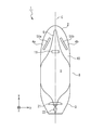
- FIG. 1B is a schematic bottom view showing an example of the configuration of the frictional resistance reduction ship according to the first embodiment of the present invention.
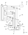
- FIG. 2 is a schematic diagram showing details of the configuration of the gas blowing device according to the first embodiment of the present invention.
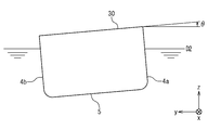
- FIG. 3 is a schematic diagram showing the tilt angle ⁇ of rolling.
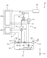
- FIG. 4 is a schematic diagram showing details of the configuration of the gas blowing device according to the second embodiment of the present invention.
- FIG. 5 is a schematic side view showing an example of the configuration of a frictional resistance reduction ship according to the third embodiment of the present invention.
- FIG. 6 is a schematic diagram showing details of the configuration of the gas blowing device according to the third embodiment of the present invention.
- FIGS. 1A and 1B are a schematic side view and a schematic bottom view showing an example of a configuration of a frictional resistance reduction type ship according to the first embodiment of the present invention.
- the ship length direction (front-rear direction), the ship width direction (left-right direction) of the hull 20 of the frictional resistance reduction type ship 1, and the directions perpendicular to them are shown as the x direction, the y direction, and the z direction, respectively.
- a line in contact with the water surface of the hull 20 floating on the still water surface is defined as a draft line DL.
- the center line of the hull 20 in the length direction (x direction) is defined as a hull center line C.
- the frictional resistance reduction type ship 1 includes a hull 20 and a gas blowing device 30.
- the hull 20 includes a bow portion 2 including a tip portion 6, an intermediate portion 8, a stern portion 3, a propeller 21, and a rudder 22.
- the hull 20 is divided into approximately three equal parts in the direction of the hull center line C, the bow side portion is the bow portion 2, the stern side portion is the stern portion 3, and the portion in between is the intermediate portion 8.
- the propeller 21 and the rudder 22 are provided in the stern part 3 on the hull center line C.
- the gas blowing device 30 is provided inside the hull 20.
- the gas blowing device 30 is configured to gas from the gas blowing portion provided on the ship side 4 and the ship bottom 5 of the bow 2 into the water so that the ship bottom 5 and the ship side 4 of the hull 20 are covered with bubbles during navigation (eg, air, main engine). Etc.).
- the gas blowing device 30 includes a plurality of gas supply devices.
- the plurality of gas supply devices are provided corresponding to a plurality of gas blowing portions provided at a plurality of positions at different water depths from the draft line DL of the hydrostatic surface in the hull outer plate 10, and gas is supplied to the plurality of gas blowing portions. Supply.
- the gas blowing device 30 includes a ship side gas supply device 70 and a ship bottom gas supply device 60.
- the ship side gas supply device 70 is provided corresponding to the ship side gas blowing part 51 provided on the ship side 4.
- the ship bottom gas supply device 60 is provided corresponding to the ship bottom gas blowing part 41 provided on the ship bottom 5.
- the ship side gas blowing part 51 and the ship bottom gas blowing part 41 are provided at positions where the water depths from the water line DL are different from each other, and the difference in water depth is H0.
- the gas blowing device 30 further includes a control device 59 that controls the ship side gas supply device 70 and the ship bottom gas supply device 60.
- the control device 59 is provided, for example, in a control room (or a steering room) of the frictional resistance reduction type ship 1.
- the ship-side gas blowing part 51 is provided on the hull outer plate 10 of the ship side 4 on both sides of the bow 2 and can blow out gas into the water.
- the starboard gas blowing section 51a provided on the starboard side 4a can blow gas into the water on the starboard side 4a.
- the port gas blowing part 51b provided on the port side 4b can blow gas into the water on the port side 4b. If ship side gas blowing-out part 51 is provided in ship side 4, there will be no restriction in particular. For example, one or a plurality of slits, circles, ellipses, oval holes, etc., through which gas can be blown out may be provided.
- the ship side gas supply device 70 includes a ship side gas delivery part 55, a ship side gas flow path 53, and a ship side gas supply part 52.
- the ship side gas delivery part 55 compresses and sends out gas.
- the ship-side gas flow channel 53 is a pipe that supplies the gas from the ship-side gas delivery unit 55 to the ship-side gas supply unit 52.
- the ship-side gas supply unit 52 is a gas supply chamber provided on the ship-side gas blowing unit 51. The gas supply chamber is provided for each of one or a plurality of holes. The gas supplied through the ship-side gas flow channel 53 is blown out from the ship-side gas blowing part 51 into the water.
- the starboard gas blowing section 51a and the portside gas blowing section 51b are not particularly limited as long as they are provided on the ship side 4, but more specifically, the number, shape, size, and arrangement are particularly limited. There is no.
- the number of holes (openings) through which gas can be blown out may be one or more.
- the shape may be a slit shape, a circular shape, an elliptical shape, an oval shape, or the like. About the magnitude
- positioning it may be parallel (aligned) with the waterline DL, the depth direction (aligned) of the ship 1 may be good, it may be along the streamline (aligned), and it may be parallel. Also good.
- a group may be formed for each of several holes (openings) and arranged at different positions.
- the ship bottom gas blowing part 41 is provided on the hull outer plate 10 of the ship bottom 5 in the bow part 2 and can blow gas into the water. If the ship bottom gas blowing part 41 is provided in the ship bottom 5, there will be no restriction
- the ship bottom gas supply device 60 includes a ship bottom gas delivery part 45, a ship bottom gas flow path 43, and a ship bottom gas supply part 42.
- the ship bottom gas delivery unit 45 compresses and delivers the gas.
- the ship bottom gas channel 43 is a pipe that supplies the gas from the ship bottom gas delivery unit 45 to the ship bottom gas supply unit 42.
- the ship bottom gas supply unit 42 is a gas supply chamber provided on the ship bottom gas blowing unit 41.
- the gas supply chamber is provided for each of one or a plurality of holes.
- the gas supplied through the ship bottom gas flow path 43 is blown out into the water from the ship bottom gas blowing portion 41.
- the ship bottom gas blowing portion 41 is not particularly limited as long as it is provided on the ship bottom 5, but more specifically, the number, shape, size, and arrangement are not particularly limited.
- the number of holes (openings) through which gas can be blown out may be one or more.
- the shape may be a slit shape, a circular shape, an elliptical shape, an oval shape, or the like.
- a fine opening may be sufficient and a larger opening may be sufficient.
- it may be parallel (aligned) with the ship length direction, may be parallel (aligned) with the ship width direction, may be along the streamline (aligned), or may be parallel good.
- a group may be formed for each of several holes (openings) and arranged at different positions.
- FIG. 2 is a schematic diagram showing details of the configuration of the gas blowing device 30.
- the ship-side gas supply device 70 includes a ship-side gas delivery unit 55, a flow meter 56, a starboard gas flow rate adjustment unit 54 a, a portside gas flow rate adjustment unit 54 b, a starboard gas supply unit 52 a as a shipside gas supply unit 52, and a portside gas.
- a supply section 52b and a ship-side gas flow path 53 are provided.
- the gas blowing device 30 may further include an inclination sensor 80.
- the ship side gas delivery unit 55 is exemplified by a compressor, a blower or a fan, and compresses and sends out the gas. It is controlled by the ship side control unit 59S of the control device 59.
- the ship-side gas flow channel 53 is a pipe connected to the ship-side gas delivery unit 55, the starboard gas supply unit 52a, and the portside gas supply unit 52b.
- the gas from the ship side gas delivery part 55 is supplied to the starboard gas supply part 52a and the portside gas supply part 52b.
- the ship-side gas flow channel 53 is branched into a starboard gas supply unit 52a and a portside gas supply unit 52b at a midway node N1.
- the flow meter 56 is provided in the middle of the ship-side gas flow channel 53.
- the flow rate of the gas flowing through the ship side gas passage 53 is measured and output to the ship side control unit 59S.
- the starboard gas flow rate adjusting portion 54a is provided in the middle of the ship side gas flow channel 53 branched to the starboard side.
- the gas flow rate to the starboard side among the gases sent from the ship side gas delivery unit 55 is adjusted. Examples include butterfly valves, needle valves or gate valves. It is controlled by the ship side control unit 59S of the control device 59.
- the starboard gas supply unit 52a is a gas supply chamber provided on the starboard gas blowing unit 51a.
- the gas adjusted by the starboard gas flow rate adjusting unit 54a is supplied to the starboard gas blowing unit 51a and blown out from there.
- the port side gas flow rate adjusting part 54b is provided in the middle of the ship side gas flow channel 53 branched to the port side.
- the gas flow rate to the port side of the gas sent from the ship side gas delivery unit 55 is adjusted. Examples include butterfly valves, needle valves or gate valves. It is controlled by the ship side control unit 59S of the control device 59.
- the port gas supply part 52b is a gas supply chamber provided on the port gas blowing part 51b. The gas adjusted by the port gas flow rate adjusting unit 54b is supplied to the port gas blowing unit 51b and blown out from there.
- the ship bottom gas supply device 60 includes a ship bottom gas delivery part 45, a flow meter 46, a ship bottom gas flow rate adjustment part 44, a ship bottom gas supply part 42, and a ship bottom gas flow path 43.
- the ship bottom gas delivery unit 45 is exemplified by a compressor, a blower or a fan, and delivers gas. Unlike the ship side gas delivery part 55, it is provided separately. It is controlled by the ship bottom controller 59B of the control device 59.
- the ship bottom gas channel 43 is a pipe connected to the ship bottom gas delivery part 45 and the ship bottom gas supply part 42.
- the gas from the ship bottom gas delivery unit 45 is supplied to the ship bottom gas supply unit 42.
- the flow meter 46 is provided in the middle of the ship bottom gas flow path 43.
- the flow rate of the gas flowing through the ship bottom gas channel 43 is measured and output to the ship bottom control unit 59B.
- the ship bottom gas flow rate adjusting unit 44 is provided in the middle of the ship bottom gas flow path 43.
- Examples include butterfly valves, needle valves or gate valves. It is controlled by the ship bottom controller 59B of the control device 59. The flow rate of the gas sent from the ship bottom gas sending part 45 is adjusted.
- the ship bottom gas supply unit 42 is a gas supply chamber provided on the ship bottom gas blowing unit 41. The gas adjusted by the ship bottom gas flow rate adjusting unit 44 is supplied to the ship bottom gas blowing unit 41 and blown out into the water therefrom.
- the ship bottom gas supply device 60 supplies gas at a relatively high pressure in order to supply gas to the ship bottom gas blowing part 41 at a relatively deep water depth.
- the ship-side gas supply device 70 supplies gas to the ship-side gas blowing part 51 (starboard gas blowing part 51a and portside gas blowing part 51b) at a relatively shallow depth, the gas is supplied at a relatively low pressure. Supply.
- the ship bottom gas supply device 60 and the ship side gas are set so as to have a pressure difference corresponding to the difference in water depth H0. It is preferable to control the pressure of the gas in the supply device 70.
- the tilt sensor 80 detects the rolling tilt angle ⁇ of the hull 20.
- the rolling inclination angle ⁇ of the hull 20 with respect to the vertical direction is detected.
- the rolling inclination angle ⁇ is defined to be positive when the hull 20 rolls so that the port side 4b is lowered.
- the detected rolling inclination angle ⁇ is output to the control device 59.
- the control device 59 includes the ship side control unit 59S and the ship bottom control unit 59B as described above.
- the ship-side control unit 59S is configured to supply a desired gas flow rate to the starboard gas blowing unit 51a and the portside gas blowing unit 51b based on the navigation conditions and sea conditions, and the starboard gas flow rate adjusting unit 54a. And the port gas flow rate adjusting unit 54b.
- the ship bottom control unit 59B controls the ship bottom gas delivery unit 45 and the ship bottom gas flow rate adjustment unit 44 so as to supply a desired gas flow rate to the ship bottom gas blowing unit 41 based on navigation conditions and sea conditions.
- the ship side control unit 59S and the ship bottom control unit 59B may perform control in cooperation with each other, or may perform control independently of each other.
- the ship-side control unit 59S is set in advance based on the navigation speed v (speedometer of the ship 1), the rolling inclination angle ⁇ (inclination sensor 80), and the wave height h (input of the observation equipment and crew of the ship 1).
- the motor rotation speed of the ship side gas delivery unit 55 or starboard gas so that the gas flow rate corresponding to the value of (v, ⁇ , h) in the table or function is supplied to the starboard gas blowing unit 51a and the portside gas blowing unit 51b.
- the opening degree of the valve of the flow rate adjusting unit 54a and the opening degree of the valve of the port gas flow rate adjusting unit 54b are controlled.
- the ship-side control unit 59S performs feedback control using the gas flow rate value of the flow meter 56.
- the ship bottom control unit 59B generates a gas flow rate corresponding to the value of (v, ⁇ , h) in a predetermined table or function based on the navigation speed v, the rolling inclination angle ⁇ , and the wave height h, and the ship bottom gas blowing unit 41.
- the motor rotation speed of the ship bottom gas delivery part 45 and the opening degree of the valve of the ship bottom gas flow rate adjustment part 44 are controlled so as to be supplied to the engine.
- the ship bottom control unit 59B performs feedback control using the gas flow rate value of the flow meter 46.
- the amount of gas supply (gas flow rate) is increased as the navigation speed v of the frictional resistance reduced ship 1 is increased, and the gas is blown out from the starboard gas blowing portion 51a, the portside gas blowing portion 51b, and the bottom gas blowing portion 41. It is preferable to increase the generated bubbles. Further, when the frictional resistance-reducing ship 1 is tilted by rolling, the water pressure at the gas blowing part on the ship side at the lower side of the inclination becomes relatively high, and the water pressure at the gas blowing part on the ship side at the upper side of the inclination is relatively high. Lower.
- the gas flow rate adjustment part connected to the gas blowing part on the ship side on the lower side of the inclination is relatively opened to increase the gas supply amount, or the gas connected to the gas blowing part on the ship side on the upper side of the inclination. It is preferable to relatively close the flow rate adjusting unit to reduce the gas supply amount or both.
- the frictional resistance reduction ship 1 operates as follows, for example.
- the ship-side control unit 59S corresponds to the values (v, ⁇ , h) from a preset table based on the navigation speed v, the rolling inclination angle ⁇ , and the wave height h.
- the gas flow rate for the starboard gas blowing part 51a and the port gas blowing part 51b is extracted.
- the motor speed of the ship side gas delivery unit 55 and the starboard gas flow rate adjustment unit 54a are supplied so that the ship side gas supply device 70 supplies the gas with the gas flow rate extracted to the starboard gas blowing unit 51a and the portside gas blowing unit 51b.
- the ship-side control unit 59S acquires the measured value of the gas flow rate from the flow meter 56 as a feedback signal, and performs feedback control.
- the flow rate of the flow meter 56 is controlled to be a predetermined flow rate, and the table corresponding to the predetermined flow rate is used.
- the ship bottom control unit 59B determines the gas flow rate for the ship bottom gas blowing unit 41 corresponding to the values of (v, ⁇ , h) from a predetermined table based on the navigation speed v, the rolling inclination angle ⁇ , and the wave height h. Extract.
- the motor rotational speed of the ship bottom gas delivery unit 45 and the opening degree of the valve of the ship bottom gas flow rate adjusting unit 44 are set so that the ship bottom gas supply device 60 supplies the gas with the gas flow rate extracted to the ship bottom gas blowing unit 41.
- the ship bottom control unit 59B acquires the measured value of the gas flow rate from the flow meter 46 as a feedback signal, and performs feedback control.
- the flow rate of the flow meter 46 is controlled to be a predetermined flow rate, and the table corresponding to the predetermined flow rate is used as the table.
- the amount of gas sent out from the starboard gas blowing portion 51a and the amount of bubbles sent out from the portside gas blowing portion 51b are balanced, and the amount of bubbles sent out from the ship bottom gas blowing portion 41 is also changed to starboard gas blowing. It is controlled to an appropriate value in relation to the amount of bubbles from the part 51a and the port gas blowing part 51b.
- Bubbles formed by the gas blown into the water from the ship-side gas blowing part 51 and the ship-bottom gas blowing part 41 flow so as to cover the ship-side 4 and the ship bottom 5, and the frictional resistance is reduced.
- different ship side gas supply apparatuses 70 and ship bottom gas supply apparatuses are provided. 60 is used to supply gas.
- one gas sending part supplies gas to the gas blowing parts that are not so different in water pressure.
- it is not necessary to adjust the pressure due to the pressure loss in the gas flow rate adjustment unit, and the energy consumption of the gas delivery unit is suppressed, and efficient gas blowing is enabled.
- the ship side gas blowing part 51 (starboard gas blowing part 51a and portside gas blowing part 51b), it can respond with one gas sending part, and can suppress manufacturing cost low.
- the width d determined that the water depth (water pressure) when providing different gas supply devices is different is small from the viewpoint of suppressing the energy consumption of the gas delivery unit.
- the gas supply device is large in view of the installation cost of the gas supply device and the influence on the hull 20 accompanying the installation. Considering both, it is considered that at least the gas blowing unit on the ship side and the gas blowing unit on the bottom of the ship are preferably provided with different gas supply devices due to the difference in water depth (water pressure) between the two.
- each flow path may be provided with other valves (eg, shut-off valve, relief valve) to ensure the reliability and safety of the operation.
- the ship bottom gas blowing part is one place and the ship side gas blowing part is mainly shown and described.
- the present embodiment is not limited to this example. That is, with respect to a larger number of ship bottom gas blowing parts and ship side gas blowing parts provided at a plurality of positions having different water depths, a gas supply device is provided corresponding to the gas blowing part for each water depth, and gas blowing (pressure By controlling the (flow rate), it is possible to deal with the same as in the case of FIGS.
- FIG. 4 is a schematic diagram showing details of the configuration of the gas blowing device 30.
- the ship-side gas supply device 70 includes a starboard starboard gas supply device 70a and a portside port gas supply device 70b.
- the starboard gas supply device 70a includes a starboard side starboard gas delivery section 55a, a flow meter 56a, a starboard gas flow rate adjustment section 54a, a starboard gas flow path 53a, and a starboard gas supply section 52a.
- the port gas supply device 70b includes a port side gas delivery unit 55b, a flow meter 56b, a port gas flow rate adjustment unit 54b, a port gas channel 53b, and a port gas supply unit 52b.
- the starboard gas supply device 70a will be described.
- the starboard gas delivery unit 55a is exemplified by a compressor, a blower or a fan, and compresses and delivers the gas. It is controlled by the ship side control unit 59S of the control device 59.
- the starboard gas passage 53a is a pipe connected to the starboard gas delivery part 55a and the starboard gas supply part 52a.
- the gas from the starboard gas delivery unit 55a is supplied to the starboard gas supply unit 52a.
- the flow meter 56a is provided in the middle of the starboard gas passage 53a. The flow rate of the gas flowing through the starboard gas passage 53a is measured and output to the ship-side control unit 59S.
- the starboard gas flow rate adjusting unit 54a is provided in the middle of the starboard gas flow path 53a.
- the flow rate of the gas delivered from the starboard gas delivery part 55a is adjusted. Examples include butterfly valves, needle valves or gate valves. It is controlled by the ship side control unit 59S of the control device 59.
- the starboard gas supply unit 52a is a gas supply chamber provided on the starboard gas blowing unit 51a. The gas adjusted by the starboard gas flow rate adjusting unit 54a is supplied to the starboard gas blowing unit 51a and blown out from there.
- the port gas supply device 70b will be described.
- the port gas delivery unit 55b is exemplified by a compressor, a blower, or a fan, and compresses and delivers the gas. It is controlled by the ship side control unit 59S of the control device 59.
- the port gas channel 53b is a pipe connected to the port gas delivery unit 55b and the port gas supply unit 52b.
- the gas from the port gas delivery unit 55b is supplied to the port gas supply unit 52b.
- the flow meter 56b is provided in the middle of the port side gas passage 53b.
- the flow rate of the gas flowing through the port gas flow path 53b is measured and output to the ship side control unit 59S.
- the port gas flow rate adjusting unit 54b is provided in the middle of the port gas flow channel 53b.
- the flow rate of the gas sent from the port gas sending part 55b is adjusted. Examples include butterfly valves, needle valves or gate valves. It is controlled by the ship side control unit 59S of the control device 59.
- the port gas supply part 52b is a gas supply chamber provided on the port gas blowing part 51b. The gas adjusted by the port gas flow rate adjusting unit 54b is supplied to the port gas blowing unit 51b and blown out from there.
- the control device 59 includes the ship side control unit 59S and the ship bottom control unit 59B as described above.
- the ship-side control unit 59S is configured to supply a desired gas flow rate to the starboard gas blowing unit 51a and the portside gas blowing unit 51b based on the navigation conditions and sea conditions, and the portside gas sending unit 55b.
- the starboard gas flow rate adjusting unit 54a and the starboard gas flow rate adjusting unit 54b are controlled.
- the ship-side control unit 59S is set in advance based on the navigation speed v (speedometer of the ship 1), the rolling inclination angle ⁇ (inclination sensor 80), and the wave height h (input of the observation equipment and crew of the ship 1).
- v speedometer of the ship 1
- ⁇ rolling inclination angle
- h wave height
- the ship-side control unit 59S is set in advance based on the navigation speed v (speedometer of the ship 1), the rolling inclination angle ⁇ (inclination sensor 80), and the wave height h (input of the observation equipment and crew of the ship 1).
- the number of revolutions of the motor of the delivery part 55b, the opening degree of the valve of the starboard gas flow rate adjustment part 54a, and the opening degree of the valve of the port side gas flow rate adjustment part 54b are controlled.
- the ship-side control unit 59S performs feedback control using the gas flow rate values of the flow meter 56a and the flow meter 56b.
- the flow rate of each of the flow meters 56a and 56b is controlled to be a predetermined flow rate, and the table or function corresponding to the predetermined flow rate is used as the table or function.
- the starboard gas blowing portion 51a and the portside gas blowing portion 51b in the ship side gas blowing portion 51 have separate starboard gas supply devices 70a and port gas supply devices 70b.
- the starboard gas sending portion 55a has the water depth of the starboard gas blowing portion 51a.
- a gas having a pressure corresponding to the water depth of the port gas blowing section 51b can be supplied from the port gas sending section 55b. That is, it is not necessary to adjust the pressure due to the pressure loss at the gas flow rate adjusting unit, and the energy consumption of the gas delivery unit is further suppressed, and more efficient gas blowing is possible.
- the ship-side gas delivery unit is not a compressor or a blower, but is a pressure adjusting unit 58 that reduces the pressure of the gas in the ship-bottom gas supply device 60. This is different from the case of the embodiment. In the following, differences from the first embodiment will be mainly described.
- FIG. 5 is a schematic side view showing an example of the configuration of the frictional resistance reduction type ship according to the third embodiment of the present invention.
- the configuration of the frictional resistance reduction type ship 1 is basically the same as that of the first embodiment (FIG. 1A). However, the configurations of the upstream portions of the ship-side gas supply device 70 and the ship-bottom gas supply device 60 in the gas blowing device 30 are different.
- the ship bottom gas supply device 60 includes a ship bottom gas delivery part 45, a first tank 47, a ship bottom gas flow path 43, and a ship bottom gas supply part 42.
- the ship bottom gas delivery unit 45 compresses and delivers the gas.
- the first tank 47 stores the gas sent from the ship bottom gas sending unit 45.
- the ship bottom gas flow path 43 is a pipe that supplies the gas in the first tank 47 (the gas from the ship bottom gas delivery part 45) to the ship bottom gas supply part 42.
- the ship bottom gas supply unit 42 is a gas supply chamber provided on the ship bottom gas blowing unit 41.
- the gas supply chamber is provided for each of one or a plurality of holes provided in the ship bottom gas blowing portion 41.
- the gas supplied through the ship bottom gas flow path 43 is blown out into the water from the ship bottom gas blowing portion 41.
- the ship-side gas supply device 70 includes a pressure adjusting unit 58, a second tank 57, a ship-side gas flow path 53, and a ship-side gas supply unit 52.
- the pressure adjusting unit 58 depressurizes the gas in the first tank 47 and sends it to the second tank 57.
- the second tank 57 stores a low-pressure gas whose pressure is lower than that of the gas in the first tank 47.
- the ship-side gas flow channel 53 is a pipe that supplies the gas in the second tank 57 (the gas from the pressure adjusting unit 58) to the ship-side gas supply unit 52.
- the ship-side gas supply unit 52 is a gas supply chamber provided on the ship-side gas blowing unit 51.
- the gas supply chamber is provided for each of one or a plurality of holes provided in the ship-side gas blowing portion 51.
- the gas supplied through the ship-side gas flow channel 53 is blown out from the ship-side gas blowing part 51 into the water.
- FIG. 6 is a schematic diagram showing details of the configuration of the gas blowing device 30.
- the ship bottom gas supply device 60 includes a ship bottom gas delivery part 45, a first tank 47, a flow meter 46, a ship bottom gas flow rate adjustment part 44, a ship bottom gas supply part 42, and a ship bottom gas flow path 43. Yes.
- the ship bottom gas delivery unit 45 is exemplified by a compressor, a blower or a fan, and delivers gas. It is controlled by the ship bottom controller 59B of the control device 59.
- the first tank 47 stores the gas (relatively high pressure) delivered from the ship bottom gas delivery unit 45.
- the ship bottom gas channel 43 is a pipe connected to the ship bottom gas delivery part 45 and the ship bottom gas supply part 42.
- a first tank 47 is connected on the way.
- the gas stored in the first tank 47 is supplied from the ship bottom gas delivery unit 45 to the ship bottom gas supply unit 42.
- the flow meter 46 is provided in the middle of the ship bottom gas flow path 43. The flow rate of the gas flowing through the ship bottom gas channel 43 is measured and output to the ship bottom control unit 59B.
- the ship bottom gas flow rate adjusting unit 44 is provided in the middle of the ship bottom gas flow path 43. Examples include butterfly valves, needle valves or gate valves. It is controlled by the ship bottom controller 59B of the control device 59. The flow rate of the gas stored in the first tank 47 and supplied to the ship bottom gas supply unit 42 is adjusted.
- the ship bottom gas supply unit 42 is a gas supply chamber provided on the ship bottom gas blowing unit 41. The gas adjusted by the ship bottom gas flow rate adjusting unit 44 is supplied to the ship bottom gas blowing unit 41 and blown out into the water therefrom.
- the ship-side gas supply device 70 includes a pressure adjustment unit 58, a second tank 57, a flow meter 56, a starboard gas flow rate adjustment unit 54a, a portside gas flow rate adjustment unit 54b, a starboard gas supply unit 52a, and a portside gas supply unit. 52b and a ship-side gas flow path 53 are provided.
- the pressure adjusting unit 58 is exemplified by a pressure adjusting valve (regulator), and depressurizes the gas (relatively high pressure) in the first tank 47 and sends the gas (relatively low pressure) to the second tank 57. It is controlled by the ship side control unit 59S of the control device 59.
- the second tank 57 stores a relatively low-pressure gas obtained by reducing the pressure in the first tank 47.
- the ship-side gas flow channel 53 is a pipe connected to the pressure adjusting unit 58, the starboard gas supply unit 52a, and the portside gas supply unit 52b. The gas supplied from the pressure adjustment unit 58 via the second tank 57 is supplied to the starboard gas supply unit 52a and the portside gas supply unit 52b.
- the ship-side gas flow channel 53 is branched into a starboard gas supply unit 52a and a portside gas supply unit 52b at a midway node N1.
- the flow meter 56 is provided in the middle of the ship-side gas flow channel 53.
- the flow rate of the gas flowing through the ship side gas passage 53 is measured and output to the ship side control unit 59S.
- the starboard gas flow rate adjusting portion 54a is provided in the middle of the ship side gas flow channel 53 branched to the starboard side.
- the gas flow rate to the starboard side of the gas sent from the second tank 57 is adjusted. Examples include butterfly valves, needle valves or gate valves. It is controlled by the ship side control unit 59S of the control device 59.
- the starboard gas supply unit 52a is a gas supply chamber provided on the starboard gas blowing unit 51a.
- the gas adjusted by the starboard gas flow rate adjusting unit 54a is supplied to the starboard gas blowing unit 51a and blown out from there.
- the port side gas flow rate adjusting part 54b is provided in the middle of the ship side gas flow channel 53 branched to the port side.
- the gas flow rate to the port side of the gas sent from the second tank 57 is adjusted. Examples include butterfly valves, needle valves or gate valves. It is controlled by the ship side control unit 59S of the control device 59.
- the port gas supply part 52b is a gas supply chamber provided on the port gas blowing part 51b.
- the gas adjusted by the port gas flow rate adjusting unit 54b is supplied to the port gas blowing unit 51b and blown out from there.
- the control device 59 includes the ship side control unit 59S and the ship bottom control unit 59B as described above.
- the ship bottom control unit 59B controls the ship bottom gas delivery unit 45 and the ship bottom gas flow rate adjustment unit 44 so as to supply a desired gas flow rate to the ship bottom gas blowing unit 41 based on navigation conditions and sea conditions.
- the ship-side control unit 59S controls the pressure adjustment unit 58 and the starboard gas flow rate adjustment so as to supply a desired gas flow rate to the starboard gas blowing unit 51a and the portside gas blowing unit 51b based on the navigation conditions and sea conditions.
- the unit 54a and the port gas flow rate adjusting unit 54b are controlled.
- the ship-side control unit 59S is set in advance based on the navigation speed v (from the speedometer of the ship 1), the rolling inclination angle ⁇ (inclination sensor 80), and the wave height h (input of the observation equipment and crew of the ship 1).
- the secondary pressure (second tank) of the pressure adjusting unit 58 so as to supply the gas flow rate corresponding to the value of (v, ⁇ , h) in the table or function to the starboard gas blowing unit 51a and the portside gas blowing unit 51b. 57), the opening degree of the valve of the starboard gas flow rate adjustment unit 54a, and the opening degree of the valve of the port side gas flow rate adjustment unit 54b.
- the ship-side control unit 59S performs feedback control using the gas flow rate value of the flow meter 56.
- the flow rate of the flow meter 56 is controlled to be a predetermined flow rate, and the table or function corresponding to the predetermined flow rate is used as the table or function.
- the ship bottom control unit 59B generates a gas flow rate corresponding to the value of (v, ⁇ , h) in a predetermined table or function based on the navigation speed v, the rolling inclination angle ⁇ , and the wave height h, and the ship bottom gas blowing unit 41.
- the motor rotation speed of the ship bottom gas delivery part 45 and the opening degree of the valve of the ship bottom gas flow rate adjustment part 44 are controlled so as to be supplied to the engine.
- the ship bottom control unit 59B performs feedback control using the gas flow rate value of the flow meter 46.
- the flow rate of the flow meter 46 is controlled to be a predetermined flow rate, and the table or function corresponding to the predetermined flow rate is used as the table or function.
- the same effect as that of the first embodiment can be obtained.
- the configuration of the gas blowing device 30 can be simplified.
- the number of gas delivery units can be reduced to one, and the cost can be reduced.
- another pressure adjusting unit 58 ′ is connected to the first tank 47, and another pressure adjusting unit 58 ′, another second tank 57 ′, another flow meter 56 ′, and port gas are used for the port gas blowing unit 51b.
- Another ship-side gas flow channel 53 ′ connected to the flow rate adjusting unit 54b and the port gas supply unit 52b is provided, and the original pressure adjusting unit 58, the second tank 57, the flow meter 56, the starboard gas flow rate adjusting unit 54a, and the starboard side are provided. It is also possible to use the ship side gas flow channel 53 connected to the gas supply unit 52a for the starboard gas blowing unit 51a. In that case, the effect which combined the effect of this Embodiment and the effect of 2nd Embodiment can be acquired.
- each gas blowing part when supplying air to each gas blowing portion in a ship where gas blowing portions are provided at a plurality of positions having different water depths from the waterline of the still water surface, energy consumption can be reduced and efficiently implemented. Become. Further, in a ship provided with gas blowing portions at a plurality of positions having different water depths from the draft line on the still water surface, it becomes possible to send out gas from each gas blowing portion in a balanced manner. In a ship where gas blowing parts are provided at a plurality of positions at different water depths from the waterline of the still water surface, each gas blowing part suppresses energy consumption even if the hull tilts and the water depths from the sea surface differ. It is possible to deliver gas in a well-balanced manner.
Landscapes
- Physics & Mathematics (AREA)
- Fluid Mechanics (AREA)
- Chemical & Material Sciences (AREA)
- Engineering & Computer Science (AREA)
- Combustion & Propulsion (AREA)
- Mechanical Engineering (AREA)
- Ocean & Marine Engineering (AREA)
- Filling Or Discharging Of Gas Storage Vessels (AREA)
Abstract
摩擦抵抗低減船舶は複数の気体吹き出し部と複数の気体供給装置とを具備している。複数の気体吹き出し部は、船舶における静水面の喫水線からの水深が異なる複数の位置に設けられ、気体を吹き出し可能である。複数の気体供給装置は、複数の気体吹き出し部に対応して設けられ、複数の気体吹き出し部に気体を供給する。
Description
本発明は、船舶に関し、特に摩擦抵抗低減型船舶に関する。
船舶の船体に作用する抵抗を低減する一手法として、船底や船側から空気(気泡)を吹き出し、船底全体を気泡で覆う方法が知られている。このような手法を用いた船舶は、摩擦抵抗低減船舶とも言われている。その摩擦抵抗低減船舶において、空気を吹き出すための空気吹き出し部は、船底又は船側に設けられている。空気吹き出し部から空気を吹き出すためには、ブロアやコンプレッサなどにより圧縮された空気を用いる必要がある。これは、空気が、船底や船側の位置での水圧に対応した圧力を有する必要があるからである。
関連する技術として、特開2010-120612号公報(特許文献1)に船体摩擦抵抗低減装置が開示されている。この船体摩擦抵抗低減装置は、複数の空気吹き出し口と、空気供給手段と、空気供給量調整手段と、水圧検出推定手段と、制御手段とを備えている。複数の空気吹き出し口は、船体の底面に幅方向に沿って設けられる。空気供給手段は、該複数の空気吹き出し口に空気を供給する。空気供給量調整手段は、該空気供給手段による前記複数の空気吹き出し口への空気供給量を調整する。水圧検出推定手段は、複数の空気吹き出し口での水圧を検出または推定する。制御手段は、該水圧検出推定手段の検出推定結果に基づいて前記複数の空気吹き出し口での空気吹き出し流量が一定となるように前記空気供給量調整手段を制御する。
この特許文献1の技術では、船底の幅方向における複数の空気吹き出し口での水圧が、船体の傾きにより互いに異なることに鑑み、複数の空気吹き出し口での空気吹き出し流量が一定となるように流量調整弁(空気供給量調整手段)を用いて空気供給量を調整する。それにより、船舶の航行状態に拘わらず、船底部の外面に沿って流れる空気の分布を幅方向で均一化にしている。
しかし、発明者の最近の研究により以下の事実が今回初めて明らかとなった。
上述の特許文献1の技術では、複数の空気吹き出し口はいずれも船底に設けられている。すなわち、静水面に浮いている場合での喫水線からの水深は、複数の空気吹き出し口において同じである。そのため、船体が傾くことによる空気吹き出し口同士での水圧の相違はそれほど大きくないと考えられる。従って、各流量調整弁(空気供給量調整手段)による流量(圧力)の調整で発生するエネルギの損失はそれほど多くないと考えられる。結果として、一つのブロア(空気供給手段)から複数の空気吹き出し口へ空気を分配しても、複数の流量調整弁(複数の空気供給量調整手段)での流量調整(又は圧力調整)によるエネルギの損失はそれほど大きくならないと考えられる。
上述の特許文献1の技術では、複数の空気吹き出し口はいずれも船底に設けられている。すなわち、静水面に浮いている場合での喫水線からの水深は、複数の空気吹き出し口において同じである。そのため、船体が傾くことによる空気吹き出し口同士での水圧の相違はそれほど大きくないと考えられる。従って、各流量調整弁(空気供給量調整手段)による流量(圧力)の調整で発生するエネルギの損失はそれほど多くないと考えられる。結果として、一つのブロア(空気供給手段)から複数の空気吹き出し口へ空気を分配しても、複数の流量調整弁(複数の空気供給量調整手段)での流量調整(又は圧力調整)によるエネルギの損失はそれほど大きくならないと考えられる。
ここで、複数の空気吹き出し口のうち、一部を船側に設け、他を船底に設ける場合について考えてみる。この場合、船側の空気吹き出し口と船底の空気吹き出し口との間で、静水面に浮いている場合の喫水線からの水深は大きく異なる。そのため、船体の傾きに拘わらず、船側の空気吹き出し口と船底の空気吹き出し口との間で水圧が大きく異なる。その結果、一つのブロア(空気供給手段)から船側の空気吹き出し口と船底の空気吹き出し口へ空気を分配する場合、何ら調整をしなければ、船側の空気吹き出し口から空気が吹き出し易くなり、船底の空気吹き出し口から空気が吹き出し難くなると考えられる。この状態を回避すべく、船側の空気吹き出し口用の流量調整弁で、船側の空気吹き出し口から空気が吹き出し難くなるように調整すると、流量調整によるエネルギ損失が大きくなると考えられる。供給される空気の圧力が、船底の深い水深(高水圧)に合わせて設定されるため、低水深(低水圧)の船側の流量調整弁で管路抵抗を増大させて、空気圧力を低下させるためである。
本発明の目的は、静水面の喫水線からの水深が異なる複数の位置にそれぞれ気体吹き出し部が設けられている船舶において、各気体吹き出し部へ空気を供給するとき、消費エネルギを抑え効率的に実施可能な摩擦抵抗低減船を提供することにある。また、静水面の喫水線からの水深が異なる複数の位置にそれぞれ気体吹き出し部が設けられている船舶において、各気体吹き出し部から気体をバランスよく送出することが可能な摩擦抵抗低減船を提供することにある。静水面の喫水線からの水深が異なる複数の位置にそれぞれ気体吹き出し部が設けられている船舶において、船体が傾いて海面からの水深が異なるようになっても、消費エネルギを抑えて各気体吹き出し部から気体をバランスよく送出することが可能な摩擦抵抗低減船を提供することにある。
この発明のこれらの目的とそれ以外の目的と利益とは以下の説明と添付図面とによって容易に確認することができる。
本発明の摩擦抵抗低減船舶は、複数の気体吹き出し部と複数の気体供給装置とを具備している。複数の気体吹き出し部は、船舶における静水面の喫水線からの水深が異なる複数の位置に設けられ、気体を吹き出し可能である。複数の気体供給装置は、複数の気体吹き出し部に対応して設けられ、複数の気体吹き出し部に気体を供給する。
上記の摩擦抵抗低減船舶において、複数の気体吹き出し部は、船底気体吹き出し部と、右舷気体吹き出し部及び左舷気体吹き出し部とを備えていることが好ましい。船底気体吹き出し部は、船舶の船底に設けられ、気体を吹き出し可能であることが好ましい。右舷気体吹き出し部及び左舷気体吹き出し部は、船底気体吹き出し部とは水深が異なる位置である、船舶の両舷の船側に設けられ、気体を吹き出し可能であることが好ましい。複数の気体供給装置は、船底気体供給装置と、船側気体供給装置とを備えていることが好ましい。船底気体供給装置は、船底気体吹き出し部に、船底用気体流路を介して気体を供給することが好ましい。船側気体供給装置は、右舷気体吹き出し部及び左舷気体吹き出し部に船底用気体流路と異なる船側用気体流路を介して気体を供給し、船底気体供給装置と異なることが好ましい。
上記の摩擦抵抗低減船舶において、船側気体供給装置は、船側気体送出部と、右舷気体流量調整部と、右舷供給部と、左舷気体流量調整部と、左舷供給部とを備えていることが好ましい。船側気体送出部は、気体を送出することが好ましい。右舷気体流量調整部は、船側気体送出部から送出された気体のうち右舷側への気体の流量を調整することが好ましい。右舷供給部は、右舷気体流量調整部から調整された気体を右舷気体吹き出し部に供給することが好ましい。左舷気体流量調整部は、船側気体送出部から送出された気体のうち左舷側への気体の流量を調整することが好ましい。左舷供給部は、左舷気体流量調整部で調整された気体を左舷気体吹き出し部に供給することが好ましい。
上記の摩擦抵抗低減船舶において、船底気体供給装置は、船底気体送出部と、船底気体流量調整部と、船底供給部とを備えていることが好ましい。船底気体送出部は、気体を送出し、船側気体送出部と異なることが好ましい。船底気体流量調整部は、船底気体送出部から送出された気体の流量を調整することが好ましい。船底供給部は、船底気体流量調整部で調整された気体を船底気体吹き出し部に供給することが好ましい。
上記の摩擦抵抗低減船舶において、船側気体供給装置は、右舷気体送出部と、右舷気体流量調整部と、右舷供給部と、左舷気体送出部と、左舷気体流量調整部と、左舷供給部とを備えていることが好ましい。右舷気体送出部は、気体を送出することが好ましい。右舷気体流量調整部は、右舷気体送出部から送出された気体の流量を調整することが好ましい。右舷供給部は、右舷気体流量調整部で調整された気体を右舷気体吹き出し部に供給することが好ましい。左舷気体送出部は、気体を送出することが好ましい。左舷気体流量調整部は、左舷気体送出部から送出された気体の流量を調整することが好ましい。左舷供給部は、左舷気体流量調整部で調整された気体を左舷気体吹き出し部に供給することが好ましい。
上記の摩擦抵抗低減船舶において、船底気体供給装置は、船底気体送出部と、船底気体流量調整部と、船底供給部とを備えていることが好ましい。船底気体送出部は、気体を送出し、船側気体送出部と異なることが好ましい。船底気体流量調整部は、船底気体送出部から送出された気体の流量を調整することが好ましい。船底供給部は、船底気体流量調整部で調整された気体を船底気体吹き出し部に供給することが好ましい。
上記の摩擦抵抗低減船舶において、船底気体供給装置は、船底気体送出部と、船底気体流量調整部と、船底供給部とを備えていることが好ましい。船底気体送出部は、気体を送出することが好ましい。船底気体流量調整部は、船底気体送出部から送出された気体の流量を調整することが好ましい。船底供給部は、船底気体流量調整部で調整された気体を船底気体吹き出し部に供給することが好ましい。船側気体供給装置は、圧力調整部と、右舷気体流量調整部と、右舷供給部と、左舷気体流量調整部と、左舷供給部とを備えていることが好ましい。圧力調整部は、船底気体送出部から送出された気体を調圧して送出することが好ましい。右舷気体流量調整部は、圧力調整部から送出された気体のうち右舷側への気体の流量を調整することが好ましい。右舷供給部は、右舷気体流量調整部で調整された気体を右舷気体吹き出し部に供給することが好ましい。左舷気体流量調整部は、圧力調整部から送出された気体のうち左舷側への気体の流量を調整することが好ましい。左供給部は、左舷気体流量調整部で調整された気体を左舷気体吹き出し部に供給することが好ましい。
上記の摩擦抵抗低減船舶において、船底気体供給装置は、船底気体送出部から送出された気体を貯蔵する第1タンクを更に備えていることが好ましい。第1タンクに貯蔵された気体が船底気体流量調整部及び圧力調整部に供給されることが好ましい。船側気体供給装置は、圧力調整部から送出された気体を貯蔵する第2タンクを更に備えていることが好ましい。第2タンクに貯蔵された気体が右舷気体流量調整部と左舷気体流量調整部に供給されることが好ましい。
以下、本発明の実施の形態に係る摩擦抵抗低減型船舶に関して、添付図面を参照して説明する。
(第1の実施の形態)
本発明の第1の実施の形態に係る摩擦抵抗低減型船舶の構成について説明する。
図1A及び図1Bは、本発明の第1の実施の形態に係る摩擦抵抗低減型船舶の構成の一例を示す概略側面図及び概略底面図である。本図において、摩擦抵抗低減型船舶1の船体20の船長方向(前後方向)、船幅方向(左右方向)及びそれらいずれにも垂直な方向が、それぞれx方向、y方向及びz方向として示されている。静水面に浮いている船体20の水面と接する線を喫水線DLとする。船体20の船長方向(x方向)の中心線を船体中心線Cとする。
本発明の第1の実施の形態に係る摩擦抵抗低減型船舶の構成について説明する。
図1A及び図1Bは、本発明の第1の実施の形態に係る摩擦抵抗低減型船舶の構成の一例を示す概略側面図及び概略底面図である。本図において、摩擦抵抗低減型船舶1の船体20の船長方向(前後方向)、船幅方向(左右方向)及びそれらいずれにも垂直な方向が、それぞれx方向、y方向及びz方向として示されている。静水面に浮いている船体20の水面と接する線を喫水線DLとする。船体20の船長方向(x方向)の中心線を船体中心線Cとする。
この摩擦抵抗低減型船舶1は、船体20と、気体吹き出し装置30とを備えている。船体20は、先端部6を含む船首部2と、中間部8と、船尾部3と、プロペラ21と、舵22とを備えている。ここでは、船体20を船体中心線Cの方向に略3等分し、船首側の部分を船首部2とし、船尾側の部分を船尾部3とし、その間の部分を中間部8としている。プロペラ21と舵22は船体中心線C上の船尾部3に設けられている。気体吹き出し装置30は、その船体20の内部に設けられている。
気体吹き出し装置30は、航行時に、船体20の船底5や船側4を気泡で覆うように、船首部2の船側4や船底5に設けられた気体吹き出し部から水中へ気体(例示:空気、主機等からの排出ガス)を吹き出す。気体吹き出し装置30は、複数の気体供給装置を備えている。複数の気体供給装置は、船体外板10における静水面の喫水線DLからの水深が異なる複数の位置に設けられた複数の気体吹き出し部に対応して設けられ、当該複数の気体吹き出し部へ気体を供給する。本実施の形態では、気体吹き出し装置30は、船側気体供給装置70と船底気体供給装置60とを備えている。船側気体供給装置70は、船側4に設けられた船側気体吹き出し部51に対応して設けられている。船底気体供給装置60は、船底5に設けられた船底気体吹き出し部41に対応して設けられている。船側気体吹き出し部51と船底気体吹き出し部41とは、互いに、喫水線DLからの水深が異なる位置に設けられ、その水深の差がH0である。気体吹き出し装置30は、船側気体供給装置70と船底気体供給装置60を制御する制御装置59を更に備えている。制御装置59は、例えば、摩擦抵抗低減型船舶1のコントロールルーム(又は操舵室)に設けられる。
船側気体吹き出し部51は、船首部2における両舷の船側4の船体外板10に設けられ、水中へ気体を吹き出し可能である。右舷船側4aに設けられた右舷気体吹き出し部51aは、右舷船側4aの水中へ気体を吹き出し可能である。左舷船側4bに設けられた左舷気体吹き出し部51bは、左舷船側4bの水中へ気体を吹き出し可能である。船側気体吹き出し部51は、船側4に設けられていれば、特に制限はない。例えば、気体が吹き出し可能な一つ又は複数のスリット状、円状、楕円状、長円状などの孔を有していても良い。船側気体供給装置70は、船側気体送出部55と、船側用気体流路53と、船側気体供給部52とを備えている。船側気体送出部55は、気体を圧縮し送出する。船側用気体流路53は、船側気体送出部55からの気体を船側気体供給部52へ供給する配管である。船側気体供給部52は、船側気体吹き出し部51上に設けられた気体供給チャンバである。気体供給チャンバは、一つ又は複数の孔ごとに設けられている。船側用気体流路53を介して供給された気体を船側気体吹き出し部51から水中へ吹き出す。
上述のように、右舷気体吹き出し部51a及び左舷気体吹き出し部51bは、船側4に設けられていれば特に制限はないが、より具体的には、その数や形状や大きさや配置には特に制限はない。例えば、気体が吹き出し可能な孔(開口部)については、その数は一つ又は複数であっても良い。その形状はスリット状、円状、楕円状、長円状などであっても良い。その大きさについては、微細な開口であっても良いし、大きめの開口であってもよい。その配置については、喫水線DLと平行(に並んで)も良いし、船舶1の深さ方向(に並んで)も良いし、流線に沿って(並んで)も良いし、並列していても良い。いくつかの孔(開口部)毎にグループを形成して互いに異なる位置に配置されていても良い。
船底気体吹き出し部41は、船首部2における船底5の船体外板10に設けられ、水中へ気体を吹き出し可能である。船底気体吹き出し部41は、船底5に設けられていれば、特に制限はない。例えば、気体が吹き出し可能な一つ又は複数のスリット状、円状、楕円状、長円状などの孔を有していても良い。船底気体供給装置60は、船底気体送出部45と、船底用気体流路43と、船底気体供給部42とを備えている。船底気体送出部45は、気体を圧縮し送出する。船底用気体流路43は、船底気体送出部45からの気体を船底気体供給部42へ供給する配管である。船底気体供給部42は、船底気体吹き出し部41上に設けられた気体供給チャンバである。気体供給チャンバは、一つ又は複数の孔ごとに設けられている。船底用気体流路43を介して供給された気体を船底気体吹き出し部41から水中へ吹き出す。
上述のように、船底気体吹き出し部41は、船底5に設けられていれば特に制限はないが、より具体的には、その数や形状や大きさや配置には特に制限はない。例えば、気体が吹き出し可能な孔(開口部)については、その数は一つ又は複数であっても良い。その形状はスリット状、円状、楕円状、長円状などであっても良い。その大きさについては、微細な開口であっても良いし、大きめの開口であってもよい。その配置については、船長方向と平行(に並んで)も良いし、船幅方向と平行(に並んで)も良いし、流線に沿って(並んで)も良いし、並列していても良い。いくつかの孔(開口部)毎にグループを形成して互いに異なる位置に配置されていても良い。
図2は、気体吹き出し装置30の構成の詳細を示す概略図である。
船側気体供給装置70は、船側気体送出部55と、流量計56と、右舷気体流量調整部54aと、左舷気体流量調整部54bと、船側気体供給部52としての右舷気体供給部52a及び左舷気体供給部52bと、船側用気体流路53を備えている。気体吹き出し装置30は、更に傾斜センサ80を備えていても良い。
船側気体供給装置70は、船側気体送出部55と、流量計56と、右舷気体流量調整部54aと、左舷気体流量調整部54bと、船側気体供給部52としての右舷気体供給部52a及び左舷気体供給部52bと、船側用気体流路53を備えている。気体吹き出し装置30は、更に傾斜センサ80を備えていても良い。
船側気体送出部55は、コンプレッサ、ブロア又はファンに例示され、気体を圧縮し送出する。制御装置59の船側用制御部59Sにより制御される。船側用気体流路53は、船側気体送出部55と右舷気体供給部52a及び左舷気体供給部52bとに接続された配管である。船側気体送出部55からの気体を右舷気体供給部52a及び左舷気体供給部52bへ供給する。船側用気体流路53は、途中のノードN1で右舷気体供給部52a及び左舷気体供給部52bへ分岐している。流量計56は、船側用気体流路53の途中に設けられている。船側用気体流路53を流れる気体の流量を計測し、船側用制御部59Sへ出力する。右舷気体流量調整部54aは、右舷側に分岐した船側用気体流路53の途中に設けられている。船側気体送出部55から送出された気体のうち右舷側への気体の流量を調整する。バタフライ弁、ニードル弁又はゲート弁に例示される。制御装置59の船側用制御部59Sにより制御される。右舷気体供給部52aは、右舷気体吹き出し部51a上に設けられた気体供給チャンバである。右舷気体流量調整部54aで調整された気体を右舷気体吹き出し部51aに供給し、そこから水中へ吹き出す。左舷気体流量調整部54bは、左舷側に分岐した船側用気体流路53の途中に設けられている。船側気体送出部55から送出された気体のうち左舷側への気体の流量を調整する。バタフライ弁、ニードル弁又はゲート弁に例示される。制御装置59の船側用制御部59Sにより制御される。左舷気体供給部52bは、左舷気体吹き出し部51b上に設けられた気体供給チャンバである。左舷気体流量調整部54bで調整された気体を左舷気体吹き出し部51bに供給し、そこから水中へ吹き出す。
船底気体供給装置60は、船底気体送出部45と、流量計46と、船底気体流量調整部44と、船底気体供給部42と、船底用気体流路43とを備えている。
船底気体送出部45は、コンプレッサ、ブロア又はファンに例示され、気体を送出する。船側気体送出部55とは異なり、別途設けられている。制御装置59の船底用制御部59Bにより制御される。船底用気体流路43は、船底気体送出部45と船底気体供給部42とに接続された配管である。船底気体送出部45からの気体を船底気体供給部42へ供給する。流量計46は、船底用気体流路43の途中に設けられている。船底用気体流路43を流れる気体の流量を計測し、船底用制御部59Bへ出力する。船底気体流量調整部44は、船底用気体流路43の途中に設けられている。バタフライ弁、ニードル弁又はゲート弁に例示される。制御装置59の船底用制御部59Bにより制御される。船底気体送出部45から送出された気体の流量を調整する。船底気体供給部42は、船底気体吹き出し部41上に設けられた気体供給チャンバである。船底気体流量調整部44で調整された気体を船底気体吹き出し部41に供給し、そこから水中へ吹き出す。
船底気体供給装置60は、相対的に水深の深い位置の船底気体吹き出し部41に気体を供給するため、相対的に高い圧力で気体を供給する。一方、船側気体供給装置70は、相対的に水深の浅い位置の船側気体吹き出し部51(右舷気体吹き出し部51a及び左舷気体吹き出し部51b)に気体を供給するため、相対的に低い圧力で気体を供給する。このとき、船底気体吹き出し部41と船側気体吹き出し部51との水深の差がH0であるので、例えば、その水深の差H0に対応する圧力差となるように、船底気体供給装置60及び船側気体供給装置70の気体の圧力を制御することが好ましい。
傾斜センサ80は、船体20のローリング傾斜角θを検出する。例えば、鉛直方向に対する船体20のローリング傾斜角θを検出する。図3に示すように、左舷船側4bが下がるように船体20がローリングしたときローリング傾斜角θが正となるように定義する。検出されたローリング傾斜角θは、制御装置59へ出力される。
制御装置59は、上述のように船側用制御部59S及び船底用制御部59Bを備えている。船側用制御部59Sは、航行条件や海象条件に基づいて、所望の気体流量を右舷気体吹き出し部51a及び左舷気体吹き出し部51bへ供給するように船側気体送出部55と、右舷気体流量調整部54aと、左舷気体流量調整部54bとを制御する。同様に、船底用制御部59Bは、航行条件や海象条件に基づいて、所望の気体流量を船底気体吹き出し部41へ供給するように船底気体送出部45と、船底気体流量調整部44とを制御する。船側用制御部59S及び船底用制御部59Bは、互いに協働して制御をおこなっても良いし、それぞれ独立して制御をおこなっても良い。
例えば、船側用制御部59Sは、航行速度v(船舶1の速度計)やローリング傾斜角θ(傾斜センサ80)や波高h(船舶1の観測機器や乗員の入力)に基づいて、予め設定されたテーブル又は関数における(v、θ、h)の値に対応した気体流量を右舷気体吹き出し部51a及び左舷気体吹き出し部51bへ供給するように、船側気体送出部55のモータ回転数や、右舷気体流量調整部54aの弁の開度や、左舷気体流量調整部54bの弁の開度を制御する。流量計56の気体流量値を用いて、船側用制御部59Sは、フィードバック制御を行う。同様に、船底用制御部59Bは、航行速度vやローリング傾斜角θや波高hに基づいて、所定テーブル又は関数における(v、θ、h)の値に対応した気体流量を船底気体吹き出し部41へ供給するように、船底気体送出部45のモータ回転数や、船底気体流量調整部44の弁の開度を制御する。流量計46の気体流量値を用いて、船底用制御部59Bは、フィードバック制御を行う。
制御としては、摩擦抵抗低減船舶1の航行速度vが上昇するほど、気体の供給量(気体流量)を増加させて、右舷気体吹き出し部51a及び左舷気体吹き出し部51bと船底気体吹き出し部41から吹き出される気泡を増加させるようにすることが好ましい。また、摩擦抵抗低減船舶1がローリングにより傾斜した場合、傾斜の下側における船側の気体吹き出し部での水圧が相対的に高くなり、傾斜の上側における船側の気体吹き出し部での水圧が相対的に低くなる。その結果、右舷気体吹き出し部51aから送出される気体の量と左舷気体吹き出し部51bから送出される気泡の量とがアンバランスとなる。したがって、それを防ぐために、傾斜の下側における船側の気体吹き出し部につながる気体流量調整部を相対的に開いて気体の供給量を増加させるか、傾斜の上側における船側の気体吹き出し部につながる気体流量調整部を相対的に閉じて気体の供給量を減少させるか、その両方を行うことが好ましい。
摩擦抵抗低減船舶1は、例えば以下のように動作する。
摩擦抵抗低減船舶1の運航時において、船側用制御部59Sは、航行速度vやローリング傾斜角θや波高hに基づいて、予め設定されたテーブルから(v、θ、h)の値に対応した右舷気体吹き出し部51a及び左舷気体吹き出し部51b用の気体流量を抽出する。そして、船側気体供給装置70が右舷気体吹き出し部51a及び左舷気体吹き出し部51bへ抽出された気体流量の気体を供給するように、船側気体送出部55のモータ回転数や、右舷気体流量調整部54aの弁の開度や、左舷気体流量調整部54bの弁の開度を制御する。そのとき、船側用制御部59Sは、流量計56から気体流量の計測値をフィードバック信号として取得して、フィードバック制御を行う。例えば、流量計56の流量を所定の流量となるように制御し、上記テーブルはその所定の流量に対応したテーブルを用いる。同様に、船底用制御部59Bは、航行速度vやローリング傾斜角θや波高hに基づいて、所定テーブルから(v、θ、h)の値に対応した船底気体吹き出し部41用の気体流量を抽出する。そして、船底気体供給装置60が船底気体吹き出し部41へ抽出された気体流量の気体を供給するように、船底気体送出部45のモータ回転数や、船底気体流量調整部44の弁の開度を制御する。そのとき、船底用制御部59Bは、流量計46から気体流量の計測値をフィードバック信号として取得して、フィードバック制御を行う。例えば、流量計46の流量を所定の流量となるように制御し、上記テーブルはその所定の流量に対応したテーブルを用いる。それにより、右舷気体吹き出し部51aから送出される気体の量と左舷気体吹き出し部51bから送出される気泡の量とがバランスするとともに、船底気体吹き出し部41から送出される気泡の量も右舷気体吹き出し部51a及び左舷気体吹き出し部51bからの気泡の量との関係で適正な値に制御される。
摩擦抵抗低減船舶1の運航時において、船側用制御部59Sは、航行速度vやローリング傾斜角θや波高hに基づいて、予め設定されたテーブルから(v、θ、h)の値に対応した右舷気体吹き出し部51a及び左舷気体吹き出し部51b用の気体流量を抽出する。そして、船側気体供給装置70が右舷気体吹き出し部51a及び左舷気体吹き出し部51bへ抽出された気体流量の気体を供給するように、船側気体送出部55のモータ回転数や、右舷気体流量調整部54aの弁の開度や、左舷気体流量調整部54bの弁の開度を制御する。そのとき、船側用制御部59Sは、流量計56から気体流量の計測値をフィードバック信号として取得して、フィードバック制御を行う。例えば、流量計56の流量を所定の流量となるように制御し、上記テーブルはその所定の流量に対応したテーブルを用いる。同様に、船底用制御部59Bは、航行速度vやローリング傾斜角θや波高hに基づいて、所定テーブルから(v、θ、h)の値に対応した船底気体吹き出し部41用の気体流量を抽出する。そして、船底気体供給装置60が船底気体吹き出し部41へ抽出された気体流量の気体を供給するように、船底気体送出部45のモータ回転数や、船底気体流量調整部44の弁の開度を制御する。そのとき、船底用制御部59Bは、流量計46から気体流量の計測値をフィードバック信号として取得して、フィードバック制御を行う。例えば、流量計46の流量を所定の流量となるように制御し、上記テーブルはその所定の流量に対応したテーブルを用いる。それにより、右舷気体吹き出し部51aから送出される気体の量と左舷気体吹き出し部51bから送出される気泡の量とがバランスするとともに、船底気体吹き出し部41から送出される気泡の量も右舷気体吹き出し部51a及び左舷気体吹き出し部51bからの気泡の量との関係で適正な値に制御される。
船側気体吹き出し部51及び船底気体吹き出し部41から水中へ吹き出される気体によって形成される気泡は、船側4及び船底5を覆うように流れ、摩擦抵抗が低減される。このとき、本実施の形態では、喫水線からの水深(すなわち水圧)が異なる位置に設けられた船側気体吹き出し部51及び船底気体吹き出し部41に対して、異なる船側気体供給装置70と船底気体供給装置60を用いて気体を供給する。このように、水深(水圧)が異なる気体吹き出し部には異なる気体供給装置を設けることにより、一つの気体送出部(コンプレッサやブロアなど)は水圧の相違のそれほど大きくない気体吹き出し部へ気体を供給することができる。それにより、気体流量調整部での圧力損失により圧力調整をする必要が無くなり、気体送出部のエネルギ消費を抑えて効率的な気体吹き出しが可能となる。
また、船側気体吹き出し部51(右舷気体吹き出し部51a及び左舷気体吹き出し部51b)としては、一つの気体送出部で対応でき、製造コストを低く抑えることができる。
なお、異なる気体供給装置を設けるときの水深(水圧)が異なると判断する幅dは、気体送出部のエネルギ消費を抑えるという観点からは、小さいことが好ましい。しかし、気体供給装置の設置コストや設置に伴う船体20への影響などの観点からは、大きいことが好ましい。その両者を考慮すると、少なくとも、船側の気体吹き出し部と、船底の気体吹き出し部とは、両者の水深(水圧)の差から、異なる気体供給装置を設けることが好ましいと考えられる。また、例えば、予想される最大ローリング傾斜角をθmaxとし、摩擦抵抗低減船舶1の最大幅をWmaxとすると、d=Wmax・sinθmaxが好ましい範囲と考えられる。また、各流路には、その動作の確実性や安全性を確保すべく他の弁(例示:遮断弁、逃がし弁)を備えていても良い。
なお、本実施の形態では、主に、船底気体吹き出し部が1箇所及び船側気体吹き出し部が2箇所の例を示して説明している。しかし、本実施の形態はこの例に限定されるものではない。すなわち、水深が互いに異なる複数の位置に設けられた更に多くの船底気体吹き出し部や船側気体吹き出し部についても、水深ごとに気体吹き出し部に対応させて気体供給装置を設けて気体の吹き出し(圧力・流量)を制御することで、図1A、図1B及び図2の場合と同様に対応可能である。
(第2の実施の形態)
本発明の第2の実施の形態に係る摩擦抵抗低減型船舶の構成について説明する。
本実施の形態では、船側気体供給装置70において、船側気体送出部55と流量計56と船側用気体流路53とが、右舷側と左舷側とで別々に設けられている点で、第1の実施の形態の場合と異なっている。以下では、第1の実施の形態と相違する点について主に説明する。
本発明の第2の実施の形態に係る摩擦抵抗低減型船舶の構成について説明する。
本実施の形態では、船側気体供給装置70において、船側気体送出部55と流量計56と船側用気体流路53とが、右舷側と左舷側とで別々に設けられている点で、第1の実施の形態の場合と異なっている。以下では、第1の実施の形態と相違する点について主に説明する。
図4は、気体吹き出し装置30の構成の詳細を示す概略図である。
船側気体供給装置70は、右舷用の右舷気体供給装置70aと左舷用の左舷気体供給装置70bとを備えている。右舷気体供給装置70aは、右舷側の右舷気体送出部55a、流量計56a、右舷気体流量調整部54a、右舷用気体流路53a及び右舷気体供給部52aを有している。左舷気体供給装置70bは、左舷側の左舷気体送出部55b、流量計56b、左舷気体流量調整部54b、左舷用気体流路53b及び左舷気体供給部52bを有している。
船側気体供給装置70は、右舷用の右舷気体供給装置70aと左舷用の左舷気体供給装置70bとを備えている。右舷気体供給装置70aは、右舷側の右舷気体送出部55a、流量計56a、右舷気体流量調整部54a、右舷用気体流路53a及び右舷気体供給部52aを有している。左舷気体供給装置70bは、左舷側の左舷気体送出部55b、流量計56b、左舷気体流量調整部54b、左舷用気体流路53b及び左舷気体供給部52bを有している。
右舷気体供給装置70aについて説明する。右舷気体送出部55aは、コンプレッサ、ブロア又はファンに例示され、気体を圧縮し送出する。制御装置59の船側用制御部59Sにより制御される。右舷用気体流路53aは、右舷気体送出部55aと右舷気体供給部52aとに接続された配管である。右舷気体送出部55aからの気体を右舷気体供給部52aへ供給する。流量計56aは、右舷用気体流路53aの途中に設けられている。右舷用気体流路53aを流れる気体の流量を計測し、船側用制御部59Sへ出力する。右舷気体流量調整部54aは、右舷用気体流路53aの途中に設けられている。右舷気体送出部55aから送出された気体の流量を調整する。バタフライ弁、ニードル弁又はゲート弁に例示される。制御装置59の船側用制御部59Sにより制御される。右舷気体供給部52aは、右舷気体吹き出し部51a上に設けられた気体供給チャンバである。右舷気体流量調整部54aで調整された気体を右舷気体吹き出し部51aに供給し、そこから水中へ吹き出す。
左舷気体供給装置70bについて説明する。左舷気体送出部55bは、コンプレッサ、ブロア又はファンに例示され、気体を圧縮し送出する。制御装置59の船側用制御部59Sにより制御される。左舷用気体流路53bは、左舷気体送出部55bと左舷気体供給部52bとに接続された配管である。左舷気体送出部55bからの気体を左舷気体供給部52bへ供給する。流量計56bは、左舷用気体流路53bの途中に設けられている。左舷用気体流路53bを流れる気体の流量を計測し、船側用制御部59Sへ出力する。左舷気体流量調整部54bは、左舷用気体流路53bの途中に設けられている。左舷気体送出部55bから送出された気体の流量を調整する。バタフライ弁、ニードル弁又はゲート弁に例示される。制御装置59の船側用制御部59Sにより制御される。左舷気体供給部52bは、左舷気体吹き出し部51b上に設けられた気体供給チャンバである。左舷気体流量調整部54bで調整された気体を左舷気体吹き出し部51bに供給し、そこから水中へ吹き出す。
制御装置59は、上述のように船側用制御部59S及び船底用制御部59Bを備えている。船側用制御部59Sは、航行条件や海象条件に基づいて、所望の気体流量を右舷気体吹き出し部51a及び左舷気体吹き出し部51bへ供給するように右舷気体送出部55aと、左舷気体送出部55bと、右舷気体流量調整部54aと、左舷気体流量調整部54bとを制御する。
例えば、船側用制御部59Sは、航行速度v(船舶1の速度計)やローリング傾斜角θ(傾斜センサ80)や波高h(船舶1の観測機器や乗員の入力)に基づいて、予め設定されたテーブル又は関数における(v、θ、h)の値に対応した気体流量を右舷気体吹き出し部51a及び左舷気体吹き出し部51bへ供給するように、右舷気体送出部55aのモータ回転数や、左舷気体送出部55bのモータ回転数や、右舷気体流量調整部54aの弁の開度や、左舷気体流量調整部54bの弁の開度を制御する。流量計56a及び流量計56bの気体流量値を用いて、船側用制御部59Sは、フィードバック制御を行う。例えば、流量計56a、56bの流量をそれぞれ所定の流量となるように制御し、上記テーブル又は関数はその所定の流量に対応したテーブル又は関数を用いる。
この場合にも、第1の実施の形態と同様の効果を得ることができる。
加えて、船側気体吹き出し部51における右舷気体吹き出し部51aと左舷気体吹き出し部51bとで別々の右舷気体供給装置70aと左舷気体供給装置70bとを有している。それにより、ローリングなどにより、船体20が傾いて、右舷気体吹き出し部51aと左舷気体吹き出し部51bとの間で水深(水圧)が異なる場合に、右舷気体送出部55aは右舷気体吹き出し部51aの水深に対応した圧力の気体を供給でき、左舷気体送出部55bは左舷気体吹き出し部51bの水深に対応した圧力の気体を供給することができる。すなわち、それにより、気体流量調整部での圧力損失により圧力調整をする必要が更に無くなり、気体送出部のエネルギ消費を更に抑えてより効率的な気体吹き出しが可能となる。
加えて、船側気体吹き出し部51における右舷気体吹き出し部51aと左舷気体吹き出し部51bとで別々の右舷気体供給装置70aと左舷気体供給装置70bとを有している。それにより、ローリングなどにより、船体20が傾いて、右舷気体吹き出し部51aと左舷気体吹き出し部51bとの間で水深(水圧)が異なる場合に、右舷気体送出部55aは右舷気体吹き出し部51aの水深に対応した圧力の気体を供給でき、左舷気体送出部55bは左舷気体吹き出し部51bの水深に対応した圧力の気体を供給することができる。すなわち、それにより、気体流量調整部での圧力損失により圧力調整をする必要が更に無くなり、気体送出部のエネルギ消費を更に抑えてより効率的な気体吹き出しが可能となる。
(第3の実施の形態)
本発明の第3の実施の形態に係る摩擦抵抗低減型船舶の構成について説明する。
本実施の形態では、船側気体供給装置70において、船側気体送出部が、コンプレッサやブロアなどではなく、船底気体供給装置60の気体の圧力を減圧する圧力調整部58である点で、第1の実施の形態の場合と異なっている。以下では、第1の実施の形態と相違する点について主に説明する。
本発明の第3の実施の形態に係る摩擦抵抗低減型船舶の構成について説明する。
本実施の形態では、船側気体供給装置70において、船側気体送出部が、コンプレッサやブロアなどではなく、船底気体供給装置60の気体の圧力を減圧する圧力調整部58である点で、第1の実施の形態の場合と異なっている。以下では、第1の実施の形態と相違する点について主に説明する。
図5は、本発明の第3の実施の形態に係る摩擦抵抗低減型船舶の構成の一例を示す概略側面図である。本図において、摩擦抵抗低減型船舶1の構成は、基本的に第1の実施の形態(図1A)の場合と同様である。ただし、気体吹き出し装置30における船側気体供給装置70及び船底気体供給装置60の上流部分の構成が異なっている。
船底気体供給装置60は、船底気体送出部45と、第1タンク47と、船底用気体流路43と、船底気体供給部42とを備えている。船底気体送出部45は、気体を圧縮し送出する。第1タンク47は、船底気体送出部45から送出された気体を貯蔵する。船底用気体流路43は、第1タンク47の気体(船底気体送出部45からの気体)を船底気体供給部42へ供給する配管である。船底気体供給部42は、船底気体吹き出し部41上に設けられた気体供給チャンバである。気体供給チャンバは、船底気体吹き出し部41に設けられた一つ又は複数の孔ごとに設けられている。船底用気体流路43を介して供給された気体を船底気体吹き出し部41から水中へ吹き出す。
船側気体供給装置70は、圧力調整部58と、第2タンク57と、船側用気体流路53と、船側気体供給部52とを備えている。圧力調整部58は、第1タンク47の気体を減圧し、第2タンク57へ送出する。第2タンク57は、第1タンク47の気体よりも減圧された低圧の気体を貯蔵する。船側用気体流路53は、第2タンク57の気体(圧力調整部58からの気体)を船側気体供給部52へ供給する配管である。船側気体供給部52は、船側気体吹き出し部51上に設けられた気体供給チャンバである。気体供給チャンバは、船側気体吹き出し部51に設けられた一つ又は複数の孔ごとに設けられている。船側用気体流路53を介して供給された気体を船側気体吹き出し部51から水中へ吹き出す。
図6は、気体吹き出し装置30の構成の詳細を示す概略図である。
船底気体供給装置60は、船底気体送出部45と、第1タンク47と、流量計46と、船底気体流量調整部44と、船底気体供給部42と、船底用気体流路43とを備えている。
船底気体供給装置60は、船底気体送出部45と、第1タンク47と、流量計46と、船底気体流量調整部44と、船底気体供給部42と、船底用気体流路43とを備えている。
船底気体送出部45は、コンプレッサ、ブロア又はファンに例示され、気体を送出する。制御装置59の船底用制御部59Bにより制御される。第1タンク47は、船底気体送出部45から送出された気体(相対的に高圧)を貯蔵する。船底用気体流路43は、船底気体送出部45と船底気体供給部42とに接続された配管である。途中に第1タンク47が接続されている。船底気体送出部45から第1タンク47に貯蔵された気体を船底気体供給部42へ供給する。流量計46は、船底用気体流路43の途中に設けられている。船底用気体流路43を流れる気体の流量を計測し、船底用制御部59Bへ出力する。船底気体流量調整部44は、船底用気体流路43の途中に設けられている。バタフライ弁、ニードル弁又はゲート弁に例示される。制御装置59の船底用制御部59Bにより制御される。第1タンク47に貯蔵され船底気体供給部42へ供給される気体の流量を調整する。船底気体供給部42は、船底気体吹き出し部41上に設けられた気体供給チャンバである。船底気体流量調整部44で調整された気体を船底気体吹き出し部41に供給し、そこから水中へ吹き出す。
船側気体供給装置70は、圧力調整部58と、第2タンク57と、流量計56と、右舷気体流量調整部54aと、左舷気体流量調整部54bと、右舷気体供給部52a及び左舷気体供給部52bと、船側用気体流路53を備えている。
圧力調整部58は、圧力調整弁(レギュレーター)に例示され、第1タンク47の気体(相対的に高圧)を減圧し、その気体(相対的に低圧)を第2タンク57へ送出する。制御装置59の船側用制御部59Sにより制御される。第2タンク57は、第1タンク47の気体を減圧した相対的に低圧の気体を貯蔵する。船側用気体流路53は、圧力調整部58と右舷気体供給部52a及び左舷気体供給部52bとに接続された配管である。圧力調整部58から第2タンク57を介して供給される気体を右舷気体供給部52a及び左舷気体供給部52bへ供給する。船側用気体流路53は、途中のノードN1で右舷気体供給部52a及び左舷気体供給部52bへ分岐している。流量計56は、船側用気体流路53の途中に設けられている。船側用気体流路53を流れる気体の流量を計測し、船側用制御部59Sへ出力する。右舷気体流量調整部54aは、右舷側に分岐した船側用気体流路53の途中に設けられている。第2タンク57から送出された気体のうち右舷側への気体の流量を調整する。バタフライ弁、ニードル弁又はゲート弁に例示される。制御装置59の船側用制御部59Sにより制御される。右舷気体供給部52aは、右舷気体吹き出し部51a上に設けられた気体供給チャンバである。右舷気体流量調整部54aで調整された気体を右舷気体吹き出し部51aに供給し、そこから水中へ吹き出す。左舷気体流量調整部54bは、左舷側に分岐した船側用気体流路53の途中に設けられている。第2タンク57から送出された気体のうち左舷側への気体の流量を調整する。バタフライ弁、ニードル弁又はゲート弁に例示される。制御装置59の船側用制御部59Sにより制御される。左舷気体供給部52bは、左舷気体吹き出し部51b上に設けられた気体供給チャンバである。左舷気体流量調整部54bで調整された気体を左舷気体吹き出し部51bに供給し、そこから水中へ吹き出す。
制御装置59は、上述のように船側用制御部59S及び船底用制御部59Bを備えている。船底用制御部59Bは、航行条件や海象条件に基づいて、所望の気体流量を船底気体吹き出し部41へ供給するように船底気体送出部45と、船底気体流量調整部44とを制御する。同様に、船側用制御部59Sは、航行条件や海象条件に基づいて、所望の気体流量を右舷気体吹き出し部51a及び左舷気体吹き出し部51bへ供給するように圧力調整部58と、右舷気体流量調整部54aと、左舷気体流量調整部54bとを制御する。
例えば、船側用制御部59Sは、航行速度v(船舶1の速度計より)やローリング傾斜角θ(傾斜センサ80)や波高h(船舶1の観測機器や乗員の入力)に基づいて、予め設定されたテーブル又は関数における(v、θ、h)の値に対応した気体流量を右舷気体吹き出し部51a及び左舷気体吹き出し部51bへ供給するように、圧力調整部58の2次圧(第2タンク57の圧力)や、右舷気体流量調整部54aの弁の開度や、左舷気体流量調整部54bの弁の開度を制御する。流量計56の気体流量値を用いて、船側用制御部59Sは、フィードバック制御を行う。例えば、流量計56の流量を所定の流量となるように制御し、上記テーブル又は関数はその所定の流量に対応したテーブル又は関数を用いる。同様に、船底用制御部59Bは、航行速度vやローリング傾斜角θや波高hに基づいて、所定テーブル又は関数における(v、θ、h)の値に対応した気体流量を船底気体吹き出し部41へ供給するように、船底気体送出部45のモータ回転数や、船底気体流量調整部44の弁の開度を制御する。流量計46の気体流量値を用いて、船底用制御部59Bは、フィードバック制御を行う。例えば、流量計46の流量を所定の流量となるように制御し、上記テーブル又は関数はその所定の流量に対応したテーブル又は関数を用いる。
この場合にも、第1の実施の形態と同様の効果を得ることができる。
加えて、気体吹き出し装置30の構成を簡素化することができる。また、気体送出部(コンプレッサやブロアなど)の台数を1台にでき、低コスト化を図ることができる。
加えて、気体吹き出し装置30の構成を簡素化することができる。また、気体送出部(コンプレッサやブロアなど)の台数を1台にでき、低コスト化を図ることができる。
なお、第1タンク47に他の圧力調整部58’を接続し、左舷気体吹き出し部51b用に他の圧力調整部58’、他の第2タンク57’、他の流量計56’、左舷気体流量調整部54b及び左舷気体供給部52bを接続された他の船側用気体流路53’を設け、元の圧力調整部58、第2タンク57、流量計56、右舷気体流量調整部54a及び右舷気体供給部52aを接続された船側用気体流路53を右舷気体吹き出し部51a用とすることも可能である。その場合、本実施の形態の効果と第2の実施の形態の効果とを併せた効果を得ることができる。
本発明により、静水面の喫水線からの水深が異なる複数の位置にそれぞれ気体吹き出し部が設けられている船舶において、各気体吹き出し部へ空気を供給するとき、消費エネルギを抑え効率的に実施可能となる。また、静水面の喫水線からの水深が異なる複数の位置にそれぞれ気体吹き出し部が設けられている船舶において、各気体吹き出し部から気体をバランスよく送出することが可能となる。静水面の喫水線からの水深が異なる複数の位置にそれぞれ気体吹き出し部が設けられている船舶において、船体が傾いて海面からの水深が異なるようになっても、消費エネルギを抑えて各気体吹き出し部から気体をバランスよく送出することが可能となる。
本発明は上記各実施の形態に限定されず、本発明の技術思想の範囲内において、各実施の形態は適宜変形又は変更され得ることは明らかである。
この出願は、2011年4月15日に出願された特許出願番号2011-090803号の日本特許出願に基づいており、その出願による優先権の利益を主張し、その出願の開示は、引用することにより、そっくりそのままここに組み込まれている。
Claims (8)
- 船舶における静水面の喫水線からの水深が異なる複数の位置に設けられ、気体を吹き出
し可能な複数の気体吹き出し部と、
前記複数の気体吹き出し部に対応して設けられ、前記複数の気体吹き出し部に気体を供
給する複数の気体供給装置と
を具備する
摩擦抵抗低減船舶。 - 請求項1に記載の摩擦抵抗低減船舶において、
前記複数の気体吹き出し部は、
前記船舶の船底に設けられ、気体を吹き出し可能な船底気体吹き出し部と、
前記船底気体吹き出し部とは前記水深が異なる位置である、前記船舶の両舷の船側に
設けられ、気体を吹き出し可能な右舷気体吹き出し部及び左舷気体吹き出し部と
を備え、
前記複数の気体供給装置は、
前記船底気体吹き出し部に、船底用気体流路を介して気体を供給する船底気体供給装置
と、
前記右舷気体吹き出し部及び前記左舷気体吹き出し部に前記船底用気体流路と異なる
船側用気体流路を介して気体を供給し、前記船底気体供給装置と異なる船側気体供給装置
と
を備えている
摩擦抵抗低減船舶。 - 請求項2に記載の摩擦抵抗低減船舶において、
前記船側気体供給装置は、
気体を送出する船側気体送出部と、
前記船側気体送出部から送出された気体のうち右舷側への気体の流量を調整する右舷
気体流量調整部と、
前記右舷気体流量調整部から調整された気体を前記右舷気体吹き出し部に供給する右
舷供給部と、
前記船側気体送出部から送出された気体のうち左舷側への気体の流量を調整する左舷
気体流量調整部と、
前記左舷気体流量調整部で調整された気体を前記左舷気体吹き出し部に供給する左舷
供給部と
を備える
摩擦抵抗低減船舶。 - 請求項3に記載の摩擦抵抗低減船舶において、
前記船底気体供給装置は、
気体を送出し、前記船側気体送出部と異なる船底気体送出部と、
前記船底気体送出部から送出された気体の流量を調整する船底気体流量調整部と、
前記船底気体流量調整部で調整された気体を前記船底気体吹き出し部に供給する船底
供給部と
を備える
摩擦抵抗低減船舶。 - 請求項2に記載の摩擦抵抗低減船舶において、
前記船側気体供給装置は、
気体を送出する右舷気体送出部と、
前記右舷気体送出部から送出された気体の流量を調整する右舷気体流量調整部と、
前記右舷気体流量調整部で調整された気体を前記右舷気体吹き出し部に供給する右舷
供給部と、
気体を送出する左舷気体送出部と、
前記左舷気体送出部から送出された気体の流量を調整する左舷気体流量調整部と、
前記左舷気体流量調整部で調整された気体を前記左舷気体吹き出し部に供給する左舷
供給部と
を備える
摩擦抵抗低減船舶。 - 請求項5に記載の摩擦抵抗低減船舶において、
前記船底気体供給装置は、
気体を送出し、前記船側気体送出部と異なる船底気体送出部と、
前記船底気体送出部から送出された気体の流量を調整する船底気体流量調整部と、
前記船底気体流量調整部で調整された気体を前記船底気体吹き出し部に供給する船底
供給部と
を備える
摩擦抵抗低減船舶。 - 請求項2に記載の摩擦抵抗低減船舶において、
前記船底気体供給装置は、
気体を送出する船底気体送出部と、
前記船底気体送出部から送出された気体の流量を調整する船底気体流量調整部と、
前記船底気体流量調整部で調整された気体を前記船底気体吹き出し部に供給する船底
供給部と
を備え、
前記船側気体供給装置は、
前記船底気体送出部から送出された気体を調圧して送出する圧力調整部と、
前記圧力調整部から送出された気体のうち右舷側への気体の流量を調整する右舷気体
流量調整部と、
前記右舷気体流量調整部で調整された気体を前記右舷気体吹き出し部に供給する右舷
供給部と、
前記圧力調整部から送出された気体のうち左舷側への気体の流量を調整する左舷気体
流量調整部と、
前記左舷気体流量調整部で調整された気体を前記左舷気体吹き出し部に供給する左舷
供給部と
を備える
摩擦抵抗低減船舶。 - 請求項7に記載の摩擦抵抗低減船舶において、
前記船底気体供給装置は、
前記船底気体送出部から送出された気体を貯蔵する第1タンクを更に備え、
前記第1タンクに貯蔵された気体が前記船底気体流量調整部及び前記圧力調整部に供
給され、
前記船側気体供給装置は、
前記圧力調整部から送出された気体を貯蔵する第2タンクを更に備え、
前記第2タンクに貯蔵された気体が右舷気体流量調整部と前記左舷気体流量調整部に
供給される
摩擦抵抗低減船舶。
Applications Claiming Priority (2)
| Application Number | Priority Date | Filing Date | Title |
|---|---|---|---|
| JP2011090803A JP5791342B2 (ja) | 2011-04-15 | 2011-04-15 | 摩擦抵抗低減型船舶 |
| JP2011-090803 | 2011-04-15 |
Publications (1)
| Publication Number | Publication Date |
|---|---|
| WO2012140946A1 true WO2012140946A1 (ja) | 2012-10-18 |
Family
ID=47009130
Family Applications (1)
| Application Number | Title | Priority Date | Filing Date |
|---|---|---|---|
| PCT/JP2012/053307 Ceased WO2012140946A1 (ja) | 2011-04-15 | 2012-02-13 | 摩擦抵抗低減型船舶 |
Country Status (2)
| Country | Link |
|---|---|
| JP (1) | JP5791342B2 (ja) |
| WO (1) | WO2012140946A1 (ja) |
Cited By (1)
| Publication number | Priority date | Publication date | Assignee | Title |
|---|---|---|---|---|
| CN110949603A (zh) * | 2019-12-09 | 2020-04-03 | 中船重工(上海)节能技术发展有限公司 | 一种适用于气层减阻船的电气控制系统及方法 |
Families Citing this family (4)
| Publication number | Priority date | Publication date | Assignee | Title |
|---|---|---|---|---|
| JP5599482B1 (ja) * | 2013-03-25 | 2014-10-01 | 三井造船株式会社 | 気泡型抵抗低減装置を備えた船舶及び船舶の抵抗低減方法 |
| JP7795879B2 (ja) * | 2021-06-28 | 2026-01-08 | ナブテスコ株式会社 | 制御装置、制御装置の制御方法、制御装置の制御プログラム |
| CN121358655A (zh) * | 2023-06-16 | 2026-01-16 | 马士基股份公司 | 用于船舶的船体的供气系统和包括所述供气系统的船舶 |
| GB2643586A (en) * | 2024-08-23 | 2026-02-25 | Silverstream Tech Limited | An apparatus for supplying air |
Citations (3)
| Publication number | Priority date | Publication date | Assignee | Title |
|---|---|---|---|---|
| JPH1024891A (ja) * | 1996-07-08 | 1998-01-27 | Ishikawajima Harima Heavy Ind Co Ltd | 船舶の摩擦抵抗低減装置 |
| JPH1159563A (ja) * | 1997-08-22 | 1999-03-02 | Ishikawajima Harima Heavy Ind Co Ltd | 摩擦低減船および空気発生装置 |
| JP2000025683A (ja) * | 1998-07-16 | 2000-01-25 | Ishikawajima Harima Heavy Ind Co Ltd | バブレーヤのrancによる弁開度自動制御方法 |
-
2011
- 2011-04-15 JP JP2011090803A patent/JP5791342B2/ja not_active Expired - Fee Related
-
2012
- 2012-02-13 WO PCT/JP2012/053307 patent/WO2012140946A1/ja not_active Ceased
Patent Citations (3)
| Publication number | Priority date | Publication date | Assignee | Title |
|---|---|---|---|---|
| JPH1024891A (ja) * | 1996-07-08 | 1998-01-27 | Ishikawajima Harima Heavy Ind Co Ltd | 船舶の摩擦抵抗低減装置 |
| JPH1159563A (ja) * | 1997-08-22 | 1999-03-02 | Ishikawajima Harima Heavy Ind Co Ltd | 摩擦低減船および空気発生装置 |
| JP2000025683A (ja) * | 1998-07-16 | 2000-01-25 | Ishikawajima Harima Heavy Ind Co Ltd | バブレーヤのrancによる弁開度自動制御方法 |
Cited By (1)
| Publication number | Priority date | Publication date | Assignee | Title |
|---|---|---|---|---|
| CN110949603A (zh) * | 2019-12-09 | 2020-04-03 | 中船重工(上海)节能技术发展有限公司 | 一种适用于气层减阻船的电气控制系统及方法 |
Also Published As
| Publication number | Publication date |
|---|---|
| JP2012224111A (ja) | 2012-11-15 |
| JP5791342B2 (ja) | 2015-10-07 |
Similar Documents
| Publication | Publication Date | Title |
|---|---|---|
| US10479461B1 (en) | Surf wake forming systems and methods with primary and secondary subtabs | |
| US20190225304A1 (en) | Dual cavity air lubrication system | |
| KR101249166B1 (ko) | 선체 마찰 저항 저감 장치 | |
| JP5791342B2 (ja) | 摩擦抵抗低減型船舶 | |
| JP4953294B2 (ja) | 船体摩擦抵抗低減装置 | |
| US10676166B1 (en) | Surf wake forming systems and methods with gyroscope force vector translation | |
| JP2014012443A (ja) | 摩擦抵抗低減船 | |
| CN105189278A (zh) | 具备气泡型阻力降低装置的船舶及船舶的阻力降低方法 | |
| SE1550022A1 (sv) | Anordning vid fartyg försett med luftkavitet | |
| JP5030080B2 (ja) | 船体摩擦抵抗低減装置 | |
| JP5185966B2 (ja) | 船舶の抵抗低減装置 | |
| JP2012001115A (ja) | ツインスケグ船 | |
| KR101324114B1 (ko) | 해수 펌프를 이용한 선박 감속 장치 및 방법 | |
| KR20180091916A (ko) | 선체 마찰 저항 저감 장치 및 선박 | |
| JP2012201338A (ja) | 摩擦抵抗低減船およびその運転方法 | |
| JP2018154199A (ja) | 船舶 | |
| KR20210050744A (ko) | 선체 하중 밸런스 제어 장치 | |
| CN103958339A (zh) | 船舶的阻力降低装置 | |
| JP2007537917A (ja) | 船の船体に加わる水の摩擦を低減する方法及び装置 | |
| WO2018168585A1 (ja) | 船舶 | |
| JP6092799B2 (ja) | 船舶及び船舶の抵抗減少方法 | |
| JPH1035482A (ja) | 船尾シール内圧調整式エアクッション船 | |
| JPH0834390A (ja) | 流体制御式フィンスタビライザ | |
| JP2026508952A (ja) | 船体用エアー潤滑システム | |
| KR200481513Y1 (ko) | 선박의 공기항력 저감장치 |
Legal Events
| Date | Code | Title | Description |
|---|---|---|---|
| 121 | Ep: the epo has been informed by wipo that ep was designated in this application |
Ref document number: 12771054 Country of ref document: EP Kind code of ref document: A1 |
|
| NENP | Non-entry into the national phase |
Ref country code: DE |
|
| 122 | Ep: pct application non-entry in european phase |
Ref document number: 12771054 Country of ref document: EP Kind code of ref document: A1 |