WO2012140751A1 - 内燃機関の制御装置 - Google Patents
内燃機関の制御装置 Download PDFInfo
- Publication number
- WO2012140751A1 WO2012140751A1 PCT/JP2011/059173 JP2011059173W WO2012140751A1 WO 2012140751 A1 WO2012140751 A1 WO 2012140751A1 JP 2011059173 W JP2011059173 W JP 2011059173W WO 2012140751 A1 WO2012140751 A1 WO 2012140751A1
- Authority
- WO
- WIPO (PCT)
- Prior art keywords
- exhaust
- engine
- control
- valve
- internal combustion
- Prior art date
Links
Images


Classifications
-
- F—MECHANICAL ENGINEERING; LIGHTING; HEATING; WEAPONS; BLASTING
- F02—COMBUSTION ENGINES; HOT-GAS OR COMBUSTION-PRODUCT ENGINE PLANTS
- F02B—INTERNAL-COMBUSTION PISTON ENGINES; COMBUSTION ENGINES IN GENERAL
- F02B37/00—Engines characterised by provision of pumps driven at least for part of the time by exhaust
- F02B37/12—Control of the pumps
- F02B37/24—Control of the pumps by using pumps or turbines with adjustable guide vanes
-
- F—MECHANICAL ENGINEERING; LIGHTING; HEATING; WEAPONS; BLASTING
- F02—COMBUSTION ENGINES; HOT-GAS OR COMBUSTION-PRODUCT ENGINE PLANTS
- F02D—CONTROLLING COMBUSTION ENGINES
- F02D13/00—Controlling the engine output power by varying inlet or exhaust valve operating characteristics, e.g. timing
- F02D13/02—Controlling the engine output power by varying inlet or exhaust valve operating characteristics, e.g. timing during engine operation
- F02D13/0203—Variable control of intake and exhaust valves
- F02D13/0215—Variable control of intake and exhaust valves changing the valve timing only
- F02D13/0219—Variable control of intake and exhaust valves changing the valve timing only by shifting the phase, i.e. the opening periods of the valves are constant
-
- F—MECHANICAL ENGINEERING; LIGHTING; HEATING; WEAPONS; BLASTING
- F02—COMBUSTION ENGINES; HOT-GAS OR COMBUSTION-PRODUCT ENGINE PLANTS
- F02D—CONTROLLING COMBUSTION ENGINES
- F02D13/00—Controlling the engine output power by varying inlet or exhaust valve operating characteristics, e.g. timing
- F02D13/02—Controlling the engine output power by varying inlet or exhaust valve operating characteristics, e.g. timing during engine operation
- F02D13/0242—Variable control of the exhaust valves only
- F02D13/0246—Variable control of the exhaust valves only changing valve lift or valve lift and timing
-
- F—MECHANICAL ENGINEERING; LIGHTING; HEATING; WEAPONS; BLASTING
- F02—COMBUSTION ENGINES; HOT-GAS OR COMBUSTION-PRODUCT ENGINE PLANTS
- F02D—CONTROLLING COMBUSTION ENGINES
- F02D13/00—Controlling the engine output power by varying inlet or exhaust valve operating characteristics, e.g. timing
- F02D13/02—Controlling the engine output power by varying inlet or exhaust valve operating characteristics, e.g. timing during engine operation
- F02D13/0273—Multiple actuations of a valve within an engine cycle
-
- F—MECHANICAL ENGINEERING; LIGHTING; HEATING; WEAPONS; BLASTING
- F02—COMBUSTION ENGINES; HOT-GAS OR COMBUSTION-PRODUCT ENGINE PLANTS
- F02D—CONTROLLING COMBUSTION ENGINES
- F02D41/00—Electrical control of supply of combustible mixture or its constituents
- F02D41/0002—Controlling intake air
- F02D41/0007—Controlling intake air for control of turbo-charged or super-charged engines
-
- F—MECHANICAL ENGINEERING; LIGHTING; HEATING; WEAPONS; BLASTING
- F02—COMBUSTION ENGINES; HOT-GAS OR COMBUSTION-PRODUCT ENGINE PLANTS
- F02D—CONTROLLING COMBUSTION ENGINES
- F02D41/00—Electrical control of supply of combustible mixture or its constituents
- F02D41/0025—Controlling engines characterised by use of non-liquid fuels, pluralities of fuels, or non-fuel substances added to the combustible mixtures
- F02D41/0047—Controlling exhaust gas recirculation [EGR]
- F02D41/006—Controlling exhaust gas recirculation [EGR] using internal EGR
-
- F—MECHANICAL ENGINEERING; LIGHTING; HEATING; WEAPONS; BLASTING
- F02—COMBUSTION ENGINES; HOT-GAS OR COMBUSTION-PRODUCT ENGINE PLANTS
- F02D—CONTROLLING COMBUSTION ENGINES
- F02D41/00—Electrical control of supply of combustible mixture or its constituents
- F02D41/0025—Controlling engines characterised by use of non-liquid fuels, pluralities of fuels, or non-fuel substances added to the combustible mixtures
- F02D41/0047—Controlling exhaust gas recirculation [EGR]
- F02D41/0077—Control of the EGR valve or actuator, e.g. duty cycle, closed loop control of position
-
- F—MECHANICAL ENGINEERING; LIGHTING; HEATING; WEAPONS; BLASTING
- F02—COMBUSTION ENGINES; HOT-GAS OR COMBUSTION-PRODUCT ENGINE PLANTS
- F02M—SUPPLYING COMBUSTION ENGINES IN GENERAL WITH COMBUSTIBLE MIXTURES OR CONSTITUENTS THEREOF
- F02M26/00—Engine-pertinent apparatus for adding exhaust gases to combustion-air, main fuel or fuel-air mixture, e.g. by exhaust gas recirculation [EGR] systems
- F02M26/01—Internal exhaust gas recirculation, i.e. wherein the residual exhaust gases are trapped in the cylinder or pushed back from the intake or the exhaust manifold into the combustion chamber without the use of additional passages
-
- F—MECHANICAL ENGINEERING; LIGHTING; HEATING; WEAPONS; BLASTING
- F02—COMBUSTION ENGINES; HOT-GAS OR COMBUSTION-PRODUCT ENGINE PLANTS
- F02M—SUPPLYING COMBUSTION ENGINES IN GENERAL WITH COMBUSTIBLE MIXTURES OR CONSTITUENTS THEREOF
- F02M26/00—Engine-pertinent apparatus for adding exhaust gases to combustion-air, main fuel or fuel-air mixture, e.g. by exhaust gas recirculation [EGR] systems
- F02M26/02—EGR systems specially adapted for supercharged engines
- F02M26/09—Constructional details, e.g. structural combinations of EGR systems and supercharger systems; Arrangement of the EGR and supercharger systems with respect to the engine
- F02M26/10—Constructional details, e.g. structural combinations of EGR systems and supercharger systems; Arrangement of the EGR and supercharger systems with respect to the engine having means to increase the pressure difference between the exhaust and intake system, e.g. venturis, variable geometry turbines, check valves using pressure pulsations or throttles in the air intake or exhaust system
-
- F—MECHANICAL ENGINEERING; LIGHTING; HEATING; WEAPONS; BLASTING
- F02—COMBUSTION ENGINES; HOT-GAS OR COMBUSTION-PRODUCT ENGINE PLANTS
- F02B—INTERNAL-COMBUSTION PISTON ENGINES; COMBUSTION ENGINES IN GENERAL
- F02B2275/00—Other engines, components or details, not provided for in other groups of this subclass
- F02B2275/14—Direct injection into combustion chamber
-
- F—MECHANICAL ENGINEERING; LIGHTING; HEATING; WEAPONS; BLASTING
- F02—COMBUSTION ENGINES; HOT-GAS OR COMBUSTION-PRODUCT ENGINE PLANTS
- F02M—SUPPLYING COMBUSTION ENGINES IN GENERAL WITH COMBUSTIBLE MIXTURES OR CONSTITUENTS THEREOF
- F02M26/00—Engine-pertinent apparatus for adding exhaust gases to combustion-air, main fuel or fuel-air mixture, e.g. by exhaust gas recirculation [EGR] systems
- F02M26/02—EGR systems specially adapted for supercharged engines
- F02M26/04—EGR systems specially adapted for supercharged engines with a single turbocharger
- F02M26/05—High pressure loops, i.e. wherein recirculated exhaust gas is taken out from the exhaust system upstream of the turbine and reintroduced into the intake system downstream of the compressor
-
- Y—GENERAL TAGGING OF NEW TECHNOLOGICAL DEVELOPMENTS; GENERAL TAGGING OF CROSS-SECTIONAL TECHNOLOGIES SPANNING OVER SEVERAL SECTIONS OF THE IPC; TECHNICAL SUBJECTS COVERED BY FORMER USPC CROSS-REFERENCE ART COLLECTIONS [XRACs] AND DIGESTS
- Y02—TECHNOLOGIES OR APPLICATIONS FOR MITIGATION OR ADAPTATION AGAINST CLIMATE CHANGE
- Y02T—CLIMATE CHANGE MITIGATION TECHNOLOGIES RELATED TO TRANSPORTATION
- Y02T10/00—Road transport of goods or passengers
- Y02T10/10—Internal combustion engine [ICE] based vehicles
- Y02T10/12—Improving ICE efficiencies
-
- Y—GENERAL TAGGING OF NEW TECHNOLOGICAL DEVELOPMENTS; GENERAL TAGGING OF CROSS-SECTIONAL TECHNOLOGIES SPANNING OVER SEVERAL SECTIONS OF THE IPC; TECHNICAL SUBJECTS COVERED BY FORMER USPC CROSS-REFERENCE ART COLLECTIONS [XRACs] AND DIGESTS
- Y02—TECHNOLOGIES OR APPLICATIONS FOR MITIGATION OR ADAPTATION AGAINST CLIMATE CHANGE
- Y02T—CLIMATE CHANGE MITIGATION TECHNOLOGIES RELATED TO TRANSPORTATION
- Y02T10/00—Road transport of goods or passengers
- Y02T10/10—Internal combustion engine [ICE] based vehicles
- Y02T10/40—Engine management systems
Definitions
- the present invention relates to a control device for an internal combustion engine.
- EGR exhaust gas recirculation
- NOx nitrogen oxide
- a method for performing EGR there is a method using burned gas of the previous cycle (hereinafter referred to as internal EGR) in addition to external EGR.
- internal EGR burned gas of the previous cycle
- Patent Document 1 discloses a technique for controlling the amount of internal EGR introduced by making the negative valve overlap period in which both the intake valve and the exhaust valve of the internal combustion engine closed are variable.
- the amount of exhaust gas introduced into the combustion chamber by performing such internal EGR varies depending on the pressure balance between the intake side and the exhaust side of the internal combustion engine.
- exhaust pulsation in which the pressure on the exhaust side fluctuates periodically occurs in the internal combustion engine. Therefore, if the internal EGR control is performed without grasping the pressure difference between the intake side and the exhaust side, it is introduced into the combustion chamber.
- the actual amount of exhaust gas introduced may differ significantly from the target amount introduced.
- the exhaust valve is opened at a timing when the exhaust side pressure falls below the intake side pressure due to exhaust pulsation, thereby scavenging the burned gas in the combustion chamber and introducing the intake air. Can be increased.
- scavenging control if the exhaust valve is opened without grasping the pressure difference between the intake side and the exhaust side, a sufficient scavenging effect may not be obtained.
- This invention is made in view of this point, and it aims at providing the control apparatus of the internal combustion engine which can control appropriately the introduction amount of the waste gas to the combustion chamber by internal EGR.
- a control apparatus for an internal combustion engine comprises a variable valve operating means capable of opening an exhaust valve of an internal combustion engine in an intake stroke in addition to a valve opening operation in an exhaust stroke, Phase changing means for changing the phase of opening and closing, and an exhaust system volume changing means capable of changing an exhaust system volume that is the sum of the volume of the exhaust manifold of the internal combustion engine and the volume of the space communicating with the exhaust manifold
- supercharging efficiency control means for controlling the supercharging efficiency of a supercharger that supercharges intake air using the energy of the exhaust gas of the internal combustion engine.
- the amount of exhaust gas introduced into the combustion chamber by the internal EGR can be appropriately controlled by the configuration including the variable valve means, the phase change means, the exhaust system volume change means, and the supercharging efficiency control means.
- variable valve operating means opens the exhaust valve of the internal combustion engine in the intake stroke in addition to the valve opening operation in the exhaust stroke according to the operating state of the internal combustion engine.
- the exhaust system volume changing means may perform control to reduce the exhaust system volume.
- control device for an internal combustion engine provides the phase change when the introduction amount of the exhaust gas introduced into the combustion chamber after the control of the exhaust system volume changing means is less than the target introduction amount.
- the means may be configured to execute control for advancing the phase of opening and closing of the exhaust valve.
- the exhaust valve opening phase is advanced to increase the pressure on the exhaust side, and the exhaust valve closing phase is advanced to confine exhaust gas in the combustion chamber, thereby reducing fuel consumption.
- the amount of exhaust gas introduced into the combustion chamber can be increased while being suppressed. Therefore, the amount of exhaust gas introduced into the combustion chamber by the internal EGR can be appropriately controlled.
- the control apparatus for an internal combustion engine provides the supercharging efficiency control when the introduction amount of the exhaust gas introduced into the combustion chamber after the control of the phase changing means is less than a target introduction amount.
- the configuration may be such that the means executes control for improving the supercharging efficiency of the supercharger.
- the amount of exhaust gas introduced into the combustion chamber can be increased by improving the supercharging efficiency of the supercharger and increasing the pressure on the exhaust side. Therefore, the amount of exhaust gas introduced into the combustion chamber by the internal EGR can be appropriately controlled.
- control device for an internal combustion engine is configured so that the supercharging efficiency control means is configured to perform the supercharging when the introduction amount of the exhaust gas introduced into the combustion chamber by the control of the variable valve means exceeds a target introduction amount.
- the structure which performs the control which reduces the supercharging efficiency of a machine may be sufficient.
- the amount of exhaust gas introduced into the combustion chamber can be reduced by reducing the supercharging efficiency of the supercharger and reducing the pressure on the exhaust side. Therefore, the amount of exhaust gas introduced into the combustion chamber by the internal EGR can be appropriately controlled.
- the phase changing means causes the valve closing phase of the exhaust valve in the exhaust stroke of the internal combustion engine to be higher than the phase of the piston top dead center according to the operating state of the internal combustion engine.
- the control for delaying the angle is performed, and the exhaust system volume changing unit executes the control for reducing the exhaust system volume.
- the variable valve operating unit controls the phase changing unit and the exhaust system volume changing unit. After the control is executed, the exhaust valve of the internal combustion engine is opened in the intake stroke in addition to the opening operation in the exhaust stroke, and the exhaust gas remaining in the combustion chamber of the internal combustion engine is caused to flow out to the exhaust side. It may be configured to execute.
- the exhaust valve can be opened when the exhaust side pressure falls below the intake side pressure in the operation region where the execution of the internal EGR is not required. Can be scavenged. Therefore, the amount of exhaust gas introduced into the combustion chamber by the internal EGR can be appropriately controlled.
- the supercharging efficiency control unit performs a supercharging pressure of the supercharger after the control of the phase changing unit and the control of the exhaust system volume changing unit are executed.
- the control for reducing the supercharging efficiency of the supercharger may be executed.
- the exhaust side pressure is reduced by reducing the supercharging efficiency of the supercharger and reducing the exhaust side pressure. Can increase the chance that the pressure falls below the pressure on the intake side. Therefore, the burned gas in the combustion chamber can be scavenged appropriately, so that the amount of exhaust gas introduced into the combustion chamber by the internal EGR can be controlled appropriately.
- control device for an internal combustion engine includes an exhaust gas recirculation passage that connects an exhaust side upstream of the supercharger and an intake side, and recirculates a part of the exhaust gas to the intake passage, and the exhaust gas recirculation passage
- the exhaust system volume changing means may be configured to reduce the exhaust system volume by closing the shut-off valve.
- the exhaust system volume of the internal combustion engine can be reduced by the volume of the exhaust gas recirculation passage, so that the pressure on the exhaust side can be controlled appropriately. Therefore, the amount of exhaust gas introduced into the combustion chamber by the internal EGR can be appropriately controlled.
- the amount of exhaust gas introduced into the combustion chamber by the internal EGR can be appropriately controlled.
- FIG. 1 is a diagram illustrating a configuration example of an engine system according to an embodiment.
- FIG. 2 is a cross-sectional view showing a configuration example of one cylinder of the engine of the embodiment.
- FIG. 3 shows the pressure behavior on the exhaust side of the engine and a valve lift example.
- FIG. 4 is a flowchart showing an example of processing of the engine ECU.
- FIG. 5 shows the pressure behavior and valve lift example on the intake side and exhaust side of the engine.
- FIG. 6 is a flowchart illustrating an example of processing of the engine ECU.
- FIG. 1 is a diagram showing a configuration example of an engine system 1 equipped with a control device for an internal combustion engine of the present invention.
- FIG. 1 shows only a part of the configuration of the engine.
- the engine system 1 shown in FIG. 1 includes an engine 100 that is a power source, and includes an engine ECU (Electronic Control Unit) 10 that comprehensively controls the operation of the engine 100.
- the engine system 1 also includes a turbocharger 14 on the downstream side of the exhaust manifold 13 of the engine 100, and a variable nozzle vane mechanism 141 that controls the supercharging efficiency of the turbocharger 14.
- the engine system 1 includes a hydraulic VVT mechanism 27 that changes the valve timing of the exhaust valve 23 of the engine 100.
- the engine system 1 includes a cutoff valve 163 at the exhaust gas inlet portion of the EGR passage 16 of the engine 100.
- the engine system 1 also includes a water temperature sensor 42 that detects the cooling water temperature of the engine 100, an exhaust temperature sensor 43 that detects the exhaust gas temperature of the engine 100, and an atmospheric pressure sensor 44 that detects the external atmospheric pressure.
- FIG. 2 is a cross-sectional view showing a configuration example of one cylinder of the engine 100 of the embodiment.
- the engine 100 is a four-cylinder diesel engine mounted on a vehicle, and each cylinder includes a piston that constitutes a combustion chamber.
- the pistons of the respective combustion chambers are slidably fitted to the cylinders of the engine 100, and are connected to the crankshaft 21 that is an output shaft member via connecting rods.
- the engine ECU 10 determines the fuel injection amount and the injection timing based on information such as the intake air amount from the air flow meter 46 and the piston position from the crank angle sensor 41 and sends a signal to the injector 17.
- the injector 17 injects fuel into the combustion chamber at the instructed fuel injection amount and injection timing in accordance with a signal from the engine ECU 10.
- the fuel injected from the injector 17 is atomized in the combustion chamber, and forms an air-fuel mixture with the intake air that flows into the combustion chamber when the intake valve opens.
- the air-fuel mixture is compressed in the combustion chamber by the upward movement of the piston and ignited to burn, and expands in the combustion chamber to lower the piston.
- the descending motion is changed to the axial rotation of the crankshaft 21 through the connecting rod, whereby the engine 100 obtains power.
- the engine 100 is not limited to four cylinders, and a multi-cylinder diesel engine can be applied.
- the engine 100 is preferably a diesel engine using light oil as a fuel, but is not limited thereto.
- Engine 100 is an example of the configuration of the internal combustion engine of the present invention.
- a crank angle sensor 41 is provided in the vicinity of the axis of the crankshaft 21.
- the crank angle sensor 41 is configured to detect the rotation angle of the crankshaft 21 axis, and transmits the detection result to the engine ECU 10.
- the engine ECU 10 acquires information related to the crank angle, such as the rotational speed and rotational angular velocity of the crankshaft 21 during operation.
- the engine ECU 10 recognizes the output of the engine 100 by calculating the engine rotational speed and the engine torque based on the acquired rotational speed and rotational angular velocity of the crankshaft 21 axis.
- a water jacket in which cooling water circulates is provided around the combustion chamber of the engine 100, and a water temperature sensor 42 for measuring the temperature of the cooling water is provided in the water jacket.
- Water temperature sensor 42 detects the temperature of the cooling water inside the water jacket and transmits the result to engine ECU 10. Thereby, engine ECU 10 recognizes the temperature of the cooling water of engine 100.
- the water temperature sensor 42 can be provided at any position where the temperature of the cooling water circulating inside the engine 100 can be detected.
- the engine ECU 10 may recognize the cooling water temperature from another detected temperature such as the exhaust gas temperature instead of the detection result of the water temperature sensor 42, or may estimate the cooling water temperature from the operation history of the engine 100. Also good.
- FIG. 2 shows one intake valve and one exhaust valve.
- An intake valve 22 is disposed at each intake port of the combustion chamber, and an intake camshaft 24 for opening and closing the intake valve 22 is disposed.
- an exhaust valve 23 is disposed at each exhaust port of the combustion chamber, and an exhaust camshaft 25 for opening and closing the exhaust valve 23 is disposed.
- the intake valve 22 and the exhaust valve 23 are opened and closed by the rotation of the intake camshaft 24 and the exhaust camshaft 25 to which the rotation of the crankshaft 21 is transmitted by a coupling mechanism (for example, a timing belt, a timing chain, etc.). Communicates and blocks the combustion chamber.
- the phases of the intake valve 22 and the exhaust valve 23 are expressed with reference to the crank angle.
- the intake camshaft 24 has an electric VVT mechanism 26 that is a variable valve mechanism (hereinafter referred to as a VVT mechanism).
- the electric VVT mechanism 26 rotates the intake camshaft 24 with an electric motor in response to an instruction from the engine ECU 10.
- the rotational phase of the intake camshaft 24 relative to the crankshaft 21 is changed, so that the valve timing of the intake valve 22 is changed.
- the rotational phase of intake camshaft 24 is detected by intake cam angle sensor 48 and output to engine ECU 10. Accordingly, the engine ECU 10 can acquire the phase of the intake camshaft 24 and can acquire the phase of the intake valve 22. Further, the phase of the intake camshaft 24 is expressed with reference to the crank angle.
- the exhaust camshaft 25 has a hydraulic VVT mechanism 27.
- the hydraulic VVT mechanism 27 rotates the exhaust camshaft 25 with an oil control valve (hereinafter referred to as OCV) according to an instruction from the engine ECU 10.
- OCV oil control valve
- the rotational phase of the exhaust camshaft 25 relative to the crankshaft 21 is changed, so that the valve timing of the exhaust valve 23 is changed.
- the rotational phase of the exhaust camshaft 25 is detected by the exhaust cam angle sensor 49 and output to the engine ECU 10.
- the engine ECU 10 can acquire the phase of the exhaust camshaft 25 and can acquire the phase of the exhaust valve 23.
- the phase of the exhaust camshaft 25 is expressed with reference to the crank angle.
- the hydraulic VVT mechanism 27 can open the exhaust valve 23 during the intake stroke of the engine 100 by adjusting the OCV according to an instruction from the engine ECU 10.
- the hydraulic VVT mechanism 27 of the present embodiment is a hydraulic drive type, but may be an electric type similar to the intake camshaft 24.
- the hydraulic VVT mechanism 27 is a configuration example of the variable valve operating means and the phase changing means of the present invention.
- the engine 100 includes a common rail type fuel injection system including an injector 17, a common rail 18, a low pressure fuel pump, a high pressure fuel pump, and the like.
- the fuel sucked from the fuel tank by the low pressure fuel pump is discharged to the common rail 18 at a high pressure by the high pressure fuel pump and accumulated.
- the common rail 18 is a container for accumulating high-pressure fuel supplied to the injector 17.
- the fuel pumped from the high-pressure fuel pump is accumulated up to the pressure required for injection in the common rail 18 and supplied to the injectors 17 of the respective combustion chambers through the high-pressure piping.
- the common rail 18 is provided with a rail pressure sensor and a pressure reducing valve.
- the engine ECU 10 instructs to open the pressure reducing valve when the fuel pressure inside the common rail 18 output from the rail pressure sensor exceeds a specified value. Then, by discharging the fuel from the pressure reducing valve, the common rail pressure is always adjusted to be equal to or lower than a specified value.
- the fuel discharged from the pressure reducing valve is returned to the fuel tank through the relief pipe.
- Each injector is equipped with an injector 17.
- the fuel supplied from the common rail 18 through the high-pressure pipe is injected and supplied to the combustion chamber in the engine cylinder by the injector 17 according to an instruction from the engine ECU 10.
- the engine ECU 10 determines the fuel injection amount and the injection timing based on the intake air amount from the air flow meter 46 and the piston position information from the crank angle sensor 41 and sends a signal to the injector 17.
- the injector 17 injects fuel into the combustion chamber at a high pressure in accordance with a signal from the engine ECU 10 at the instructed fuel injection amount / injection timing.
- the leaked fuel from the injector 17 is returned to the fuel tank through the relief pipe.
- the injector 17 can be mounted at an arbitrary position in the combustion chamber according to the specifications of the engine 100.
- An intake manifold 11 that communicates with each combustion chamber is connected to each combustion chamber of the engine 100.
- the intake manifold 11 is connected to an air cleaner by an intake passage 12 via an air flow meter 46, a diesel throttle 19, an intercooler, and a compressor of a turbocharger 14, and intake air taken from the outside of the engine 100 is introduced into each combustion chamber. Introduce.
- the diesel throttle 19 is provided with a throttle position sensor 47.
- the air flow meter 46 and the throttle position sensor 47 detect the amount of intake air passing through the intake passage 12 and the valve opening of the diesel throttle 19, respectively, and transmit the detection results to the engine ECU 10.
- the engine ECU 10 recognizes the amount of intake air introduced into the intake manifold 11 based on the transmitted detection result, and adjusts the valve opening degree of the diesel throttle 19 so that the intake air necessary for the operation of the engine 100 is converted into the combustion chamber.
- the diesel throttle 19 preferably uses a throttle-by-wire system using a step motor, but other mechanisms that can arbitrarily change the valve opening of the diesel throttle 19 may be applied.
- an exhaust manifold 13 communicating with each combustion chamber is connected to each combustion chamber of the engine 100.
- the exhaust manifold 13 is connected to the exhaust purification device 30 via the exhaust turbine 15 of the turbocharger 14 by the exhaust passage 15, and exhausts the exhaust gas after combustion to the outside of the engine 100.
- the turbocharger 14 uses the kinetic energy of the exhaust gas to rotate the exhaust turbine, compresses the intake air that has passed through the air cleaner, and sends it to the intercooler. The compressed intake air is cooled by the intercooler and then introduced into the intake manifold 11.
- the turbocharger 14 is a variable nozzle turbocharger (hereinafter abbreviated as VNT), and a variable nozzle vane mechanism 141 is provided on the exhaust turbine side. By adjusting the opening of the variable nozzle vane mechanism 141, the inflow angle of the exhaust gas to the turbine impeller blades is controlled, and the supercharging pressure of the intake air introduced into the intake manifold 11 is adjusted.
- the turbocharger 14 is not limited to the VNT, and may be configured to adjust the supercharging pressure (control of the exhaust gas energy utilization rate) using a waste gate.
- the turbocharger 14 is a configuration example of the supercharger according to the present invention.
- the variable nozzle vane mechanism 141 is a configuration example of the supercharging efficiency control means of the present invention.
- the exhaust purification device 30 purifies the exhaust gas of the engine 100, and includes a purification catalyst 31 that purifies NOx, HC, and CO in the exhaust gas, and a DPF 32 that collects particulate matter (PM) such as soot. Have.
- the exhaust purification device 30 may apply a DPNR (Diesel Particulate NOx Reduction system) in which a particulate filter is combined with a NOx storage reduction catalyst.
- DPNR Diesel Particulate NOx Reduction system
- the exhaust passage 15 upstream of the exhaust purification device 30 is provided with an A / F sensor 45 that detects the air-fuel ratio of the engine 100 and an exhaust temperature sensor 43 that detects the temperature of the exhaust gas.
- the engine ECU 10 can recognize the air-fuel ratio of the engine 100 and the temperature of the exhaust gas in various load states.
- the exhaust manifold 13 is communicated with the intake manifold 11 by an EGR passage 16.
- the exhaust gas flowing into the EGR passage 16 is cooled by the EGR cooler 161 and then proceeds to the intake manifold 11 while the flow rate is adjusted by the EGR valve 162, and is introduced into the combustion chamber together with the intake air.
- the EGR valve 162 adjusts the amount of exhaust gas recirculated to the intake manifold 11 to an appropriate amount by adjusting the valve opening according to a command from the engine ECU 10.
- the EGR passage 16, the EGR cooler 161, and the EGR valve 162 function as an external EGR for recirculating and supplying a part of the exhaust gas flowing through the exhaust manifold 13 to the intake manifold 11.
- the EGR passage 16 is a configuration example of the exhaust gas recirculation passage of the present invention.
- the shut-off valve 163 is provided at a connection portion between the exhaust manifold 13 and the EGR passage 16, that is, an exhaust gas inlet portion of the EGR passage 16.
- the shut-off valve 163 is configured to be able to shut off the EGR passage 16 in accordance with an instruction from the engine ECU 10.
- the exhaust system volume of the engine 100 (at least the sum of the volumes of the exhaust manifold 13 and the EGR passage 16) can be reduced by the volume of the EGR passage 16.
- the exhaust system volume of the engine 100 can be increased by the volume of the EGR passage 16.
- shutoff valve 163 can be provided at an arbitrary position of the EGR passage 16, but by providing the shutoff valve 163 at the exhaust gas inlet portion of the EGR passage 16, the exhaust system volume of the engine 100 can be greatly changed.
- the shutoff valve 163 is an example of the configuration of the exhaust system volume changing means of the present invention.
- the atmospheric pressure sensor 44 detects the atmospheric pressure outside the vehicle on which the engine 100 is mounted, and transmits the result to the engine ECU 10. Thereby, the engine ECU 10 recognizes the atmospheric pressure outside the vehicle.
- the engine ECU 10 includes a CPU (Central Processing Unit) that performs arithmetic processing, a ROM (Read Only Memory) that stores programs, a RAM (Random Access Memory) and NVRAM (Non Volatile RAM) that store data and the like. Computer.
- the engine ECU 10 reads the detection results of a plurality of sensors provided in each part of the engine 100, and controls the operation of the engine 100 in an integrated manner based on the detection results.
- the engine ECU 10 adjusts the hydraulic VVT mechanism 27, the shutoff valve 163, and the variable nozzle vane mechanism 141 according to the operating state of the engine 100, and executes control (internal EGR) for introducing exhaust gas into the combustion chamber of the engine 100.
- control internal EGR which engine ECU10 performs is demonstrated.
- engine ECU 10 determines whether or not there is a request to execute internal EGR of engine 100 based on the received detection results of water temperature sensor 42, exhaust temperature sensor 43 and atmospheric pressure sensor 44. Specifically, the engine ECU 10 executes internal EGR when the temperature of the cooling water detected by the water temperature sensor 42 is lower than a predetermined temperature (for example, 50 ° C.) at which it can be determined that the engine 100 is in a cold operation state. Judge that there is a request to do. Further, the engine ECU 10 determines that there is a request to execute internal EGR when the temperature of the exhaust gas detected by the exhaust temperature sensor 43 is lower than a predetermined temperature (for example, 50 ° C.) that can be determined to be low.
- a predetermined temperature for example, 50 ° C.
- the engine ECU 10 has a request to execute internal EGR when the external atmospheric pressure detected by the atmospheric pressure sensor 44 is less than a predetermined atmospheric pressure (for example, 900 hPa) at which it can be determined that the vehicle on which the engine 100 is mounted is at a high altitude.
- a predetermined atmospheric pressure for example, 900 hPa
- the engine 100 when the engine 100 is in a cold operation state or in a low output region, the temperature of the exhaust gas is relatively low, so that when exhaust gas (external EGR) cooled through the EGR passage 16 is introduced into the combustion chamber, The combustion temperature may decrease excessively and combustion may worsen.
- the atmospheric pressure outside the engine 100 when the atmospheric pressure outside the engine 100 is low, the amount of oxygen introduced into the combustion chamber is lower than usual, so if a lower temperature external EGR is introduced into the combustion chamber, the amount of oxygen is insufficient. Combustion may worsen. Therefore, for example, when the engine 100 is in such an operation region, the exhaust gas of the previous cycle (internal EGR) having a relatively high temperature is introduced into the combustion chamber, thereby suppressing NOx emission while suppressing deterioration of combustion. Can be reduced.
- the engine ECU 10 may recognize the exhaust gas temperature of the engine 100 based on the output of the engine 100 calculated from the detection result of the crank angle sensor 41 instead of the detection result of the exhaust temperature sensor 43.
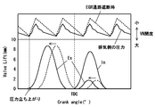
- FIG. 3 shows the pressure behavior on the exhaust side of the engine 100 and a valve lift example.
- FIG. 3 shows the behavior of a four-cylinder engine as an example of a multi-cylinder engine.
- the increase in the exhaust side pressure occurs in the exhaust stroke of each cylinder, so that exhaust pulsation in which the exhaust side pressure of the engine 100 fluctuates periodically occurs.
- the pressure on the exhaust side increases because the cylinders after the one cylinder are in the exhaust stroke. Therefore, when the exhaust valve 23 is opened during an intake stroke of a certain cylinder, a part of the exhaust gas that has flowed to the exhaust side in the previous cycle due to a high pressure on the exhaust side flows into the combustion chamber.
- the exhaust gas (internal EGR) of the previous cycle can be introduced into the combustion chamber.
- engine ECU 10 determines whether or not the actual introduction amount of exhaust gas (internal EGR) introduced into the combustion chamber of engine 100 is less than the target introduction amount.
- internal EGR exhaust gas
- a correlation map between the supercharging pressure and the in-cylinder gas amount is prepared in advance for each output of the engine 100 and stored in the ROM of the engine ECU 10 so that the actual introduction amount of the internal EGR is less than the target introduction amount. It is possible to quickly and appropriately determine whether or not.
- the engine ECU 10 instructs the variable nozzle vane mechanism 141 to increase the opening, Reduce feed efficiency.
- the engine ECU 10 executes control to increase the opening degree of the variable nozzle vane mechanism 141 until the actual introduction amount of the internal EGR reaches the target introduction amount.
- the engine ECU 10 determines that the actual introduction amount of the internal EGR is less than the target introduction amount, the engine ECU 10 instructs the shut-off valve 163 to close to shut off the EGR passage 16, thereby reducing the exhaust system volume of the engine 100.
- the engine ECU 10 instructs the shut-off valve 163 to close to shut off the EGR passage 16, thereby reducing the exhaust system volume of the engine 100.
- the exhaust system volume of the engine 100 is reduced, the volume in which exhaust gas can flow is reduced and the amplitude of exhaust pulsation increases (see FIG. 3). Therefore, when the exhaust valve 23 is opened during the intake stroke, the combustion chamber The amount of internal EGR introduced into the increases. Further, even if the EGR passage 16 is shut off during the operation of the engine 100, the fuel consumption does not deteriorate. Therefore, the amount of internal EGR introduced into the combustion chamber can be increased without deteriorating the fuel consumption by blocking the EGR passage 16 and reducing the exhaust system volume.
- the engine ECU 10 determines whether or not the actual introduction amount of the internal EGR introduced into the combustion chamber of the engine 100 is less than the target introduction amount. When the engine ECU 10 determines that the actual introduction amount of the internal EGR is not less than the target introduction amount (greater than or equal to the target introduction amount), the engine ECU 10 instructs the variable nozzle vane mechanism 141 to increase the opening degree as described above. The supercharging efficiency of the turbocharger 14 is reduced.
- the engine ECU 10 determines that the actual introduction amount of the internal EGR is less than the target introduction amount, the engine ECU 10 instructs the hydraulic VVT mechanism 27 to advance the phase of opening and closing of the exhaust valve 23 from the current state (See FIG. 3).
- the rise of the exhaust side pressure in the engine 100 is determined by the engine speed and the opening timing of the exhaust valve.
- the exhaust side pressure increases as the opening timing of the exhaust valve 23 becomes earlier. Therefore, the phase of the opening of the exhaust valve 23 in the exhaust stroke is advanced from the current state, so that the internal EGR introduced into the combustion chamber when the exhaust valve 23 is opened in the intake stroke by increasing the pressure on the exhaust side. The amount can be increased.
- the phase of closing the exhaust valve 23 it is possible to suppress exhaust gas (internal EGR) from being trapped in the combustion chamber and flowing out to the exhaust side. Further, even if the phase of opening and closing of the exhaust valve 23 is advanced from the current state during the operation of the engine 100, the degree of deterioration in fuel consumption is small. Therefore, the amount of exhaust gas introduced into the combustion chamber can be increased while the deterioration of fuel consumption is suppressed by advancing the valve opening and closing phases of the exhaust valve 23 from the current state. In this case, the amount of advancement of the phase of the exhaust valve 23 can be set based on a correlation map between the output of the engine 100 and the amount of advancement created in advance by a bench test or the like.
- the engine ECU 10 determines whether or not the actual introduction amount of the internal EGR introduced into the combustion chamber of the engine 100 is less than the target introduction amount. .
- the engine ECU 10 determines that the actual introduction amount of the internal EGR is not less than the target introduction amount (greater than or equal to the target introduction amount)
- the engine ECU 10 instructs the variable nozzle vane mechanism 141 to increase the opening degree as described above. The supercharging efficiency of the turbocharger 14 is reduced.
- the engine ECU 10 determines that the actual introduction amount of the internal EGR is less than the target introduction amount, the engine ECU 10 instructs the variable nozzle vane mechanism 141 to reduce the opening, thereby improving the supercharging efficiency of the turbocharger 14.
- the opening degree of the variable nozzle vane mechanism 141 is made smaller, more exhaust gas flows into the turbine impeller blades, so that the exhaust gas flow resistance of the engine 100 increases and the exhaust side pressure rises. Therefore, the amount of internal EGR introduced into the combustion chamber when the exhaust valve 23 is opened during the intake stroke can be increased.
- the opening degree of the variable nozzle vane mechanism 141 is made smaller during the operation of the engine 100, the pump loss increases and the fuel consumption deteriorates.
- the introduction amount of the internal EGR is increased by the above-described two controls and is closer to the target introduction amount. Therefore, the degree of change in the opening degree of the variable nozzle vane mechanism 141 can be further reduced. it can. That is, the engine ECU 10 can appropriately control the amount of exhaust gas introduced into the combustion chamber by the internal EGR while minimizing the deterioration of the fuel consumption of the engine 100 by executing these controls.
- the engine ECU 10 repeats the above control until the actual introduction amount of the internal EGR into the combustion chamber reaches the target introduction amount.
- the engine ECU 10 is an example of the configuration of the variable valve means, phase change means, exhaust system volume change means, and supercharging efficiency control means of the present invention.
- the engine system 1 of the present embodiment adjusts the hydraulic VVT mechanism 27, the shut-off valve 163, and the variable nozzle vane mechanism 141 according to the operating state of the engine 100, whereby the internal EGR to the combustion chamber of the engine 100 is adjusted.
- the amount introduced can be controlled appropriately.
- the engine system 1 according to the present embodiment executes control for blocking the EGR passage 16 that has the least adverse effect on fuel efficiency when the actual introduction amount of the internal EGR into the combustion chamber is less than the target introduction amount. Increase the amount of internal EGR introduced. Then, control is performed to further advance the phase of the exhaust valve 23 that has less adverse effects on fuel consumption, and then control to reduce the opening of the variable nozzle vane mechanism 141 is performed. In other words, the control with little adverse effect on the fuel efficiency is executed with priority, so that the introduction amount of the internal EGR into the combustion chamber can be increased while suppressing the deterioration of the fuel efficiency of the engine 100 to the minimum.
- FIG. 4 is a flowchart illustrating an example of processing of the engine ECU 10.
- the engine system 1 of the present embodiment includes a hydraulic VVT mechanism 27, a shutoff valve 163, and a variable nozzle vane mechanism 141, and adjusts the hydraulic VVT mechanism 27, the shutoff valve 163, and the variable nozzle vane mechanism 141 according to the operating state of the engine 100.
- the engine ECU 10 executes control for adjusting the amount of internal EGR introduced into the combustion chamber.
- the control of the engine ECU 10 is started when the ignition switch is turned on and the engine 100 is started, and the following control process is repeated while the engine 100 is in operation.
- the engine ECU 10 always receives the detection results of the water temperature sensor 42, the exhaust temperature sensor 43, and the atmospheric pressure sensor 44 during the control process.
- step S1 the engine ECU 10 determines whether or not there is a request to execute internal EGR of the engine 100 based on the received detection results of the water temperature sensor 42, the exhaust temperature sensor 43, and the atmospheric pressure sensor 44.
- step S1 / NO If there is no request to execute internal EGR (step S1 / NO), engine ECU 10 ends the control process. If there is a request to execute internal EGR (step S1 / YES), engine ECU 10 proceeds to next step S2.
- step S2 the engine ECU 10 instructs the hydraulic VVT mechanism 27 to open the exhaust valve 23 of the engine 100 in the intake stroke in addition to the valve opening operation in the exhaust stroke, and part of the exhaust gas that has flowed out to the exhaust side. Introduce into the combustion chamber.
- step S2 the engine ECU 10 finishes the process of step S2, the process proceeds to the next step S3.
- step S3 the engine ECU 10 determines whether the actual introduction amount of the internal EGR introduced into the combustion chamber of the engine 100 is less than the target introduction amount.
- the engine ECU 10 proceeds to step S9. If the actual introduction amount of the internal EGR is less than the target introduction amount (step S3 / YES), the engine ECU 10 proceeds to the next step S4.
- step S4 the engine ECU 10 instructs the shut-off valve 163 to shut off the EGR passage 16 to increase the pressure on the exhaust side by reducing the exhaust system volume of the engine 100.
- step S5 the engine ECU 10 instructs the shut-off valve 163 to shut off the EGR passage 16 to increase the pressure on the exhaust side by reducing the exhaust system volume of the engine 100.
- step S5 the engine ECU 10 determines whether or not the actual introduction amount of the internal EGR introduced into the combustion chamber of the engine 100 after the processing in step S4 is less than the target introduction amount. If the actual introduction amount of the internal EGR is not less than the target introduction amount (greater than the target introduction amount) (step S5 / NO), the engine ECU 10 proceeds to step S9. If the actual introduction amount of the internal EGR is less than the target introduction amount (step S5 / YES), the engine ECU 10 proceeds to the next step S6.
- step S6 the engine ECU 10 instructs the hydraulic VVT mechanism 27 to advance the opening and closing phases of the exhaust valve 23 from the current state, and the internal EGR is discharged from the combustion chamber while increasing the exhaust side pressure. It is suppressed that it is done.
- step S7 the engine ECU 10 proceeds to the next step S7.
- step S7 the engine ECU 10 determines whether or not the actual introduction amount of the internal EGR introduced into the combustion chamber of the engine 100 after the processing in step S6 is less than the target introduction amount. If the actual introduction amount of the internal EGR is not less than the target introduction amount (greater than or equal to the target introduction amount) (step S7 / NO), the engine ECU 10 proceeds to step S9. If the actual introduction amount of the internal EGR is less than the target introduction amount (step S7 / YES), the engine ECU 10 proceeds to the next step S8.
- step S8 the engine ECU 10 instructs the variable nozzle vane mechanism 141 to reduce the opening, thereby improving the supercharging efficiency of the turbocharger 14 and increasing the pressure on the exhaust side.
- the engine ECU 10 ends the control process when the process of step S8 is completed.
- step S9 the engine ECU 10 instructs the variable nozzle vane mechanism 141 to increase the opening, thereby reducing the supercharging efficiency of the turbocharger 14 and reducing the pressure on the exhaust side.
- step S9 the engine ECU 10 ends the control process.
- the engine system of the present embodiment can open the engine ECU and the exhaust valve of the engine in the intake stroke in addition to the valve opening operation in the exhaust stroke, and can open and close the exhaust valve.
- a hydraulic VVT mechanism that changes the phase a shut-off valve that can shut off the EGR passage connected to the exhaust manifold, and a variable nozzle vane mechanism that controls the supercharging efficiency of the turbocharger, and according to the operating state of the engine, the hydraulic VVT By adjusting the mechanism, the shutoff valve, and the variable nozzle vane mechanism, the amount of internal EGR introduced into the engine combustion chamber can be appropriately controlled.
- the engine system of the present embodiment gives priority to the control with less adverse effect on the fuel consumption when the actual introduction amount of the internal EGR into the combustion chamber is less than the target introduction amount, thereby reducing the fuel consumption of the engine.
- the amount of internal EGR introduced into the combustion chamber can be increased while suppressing deterioration to a minimum.
- Example 2 of the present invention will be described.
- the engine system 2 of the present embodiment opens the exhaust valve when the exhaust side pressure falls below the intake side pressure in the operation region where the execution of the internal EGR of the engine 100 is not required.
- the engine system 1 is different from the engine system 1 in that scavenging control is performed.
- the engine system 2 of the present embodiment adjusts the hydraulic VVT mechanism 27, the shutoff valve 163, and the variable nozzle vane mechanism 141 according to the operating state of the engine 100, so that the exhaust side pressure is exhausted at a timing lower than the intake side pressure.
- Control for opening the valve 23 and scavenging the exhaust gas in the combustion chamber can be executed. The scavenging control executed by the engine ECU 10 will be described below.
- the engine ECU 10 determines whether there is a request to execute the scavenging control of the engine 100 based on the received detection result of the crank angle sensor 41. Specifically, the engine ECU 10 performs scavenging control when the crank angular acceleration detected by the crank angle sensor 41 is equal to or greater than a predetermined angular acceleration at which it can be determined that the vehicle on which the engine 100 is mounted is in an acceleration state or an uphill state. Determine that there is a request to execute. In this case, the engine ECU 10 is not limited to the transmission information from the crank angle sensor 41, and may determine the scavenging control execution request based on other information such as the accelerator operation information of the driver.
- FIG. 5 shows the pressure behavior on the intake side and the exhaust side of the engine 100 and an example of valve lift.
- FIG. 5 shows the behavior of a four-cylinder engine as an example of a multi-cylinder engine. In the exhaust stroke of one cylinder in which the engine 100 is located, if the valve closing phase of the exhaust valve 23 is advanced from the phase of the piston top dead center, that is, if the exhaust valve 23 is closed while the piston is moving up, combustion occurs.
- Exhaust gas (internal EGR) remains without being exhausted from the chamber.
- exhaust valve 23 is closed after the piston top dead center, that is, when the exhaust valve 23 is closed after the piston is raised, most of the exhaust gas (internal EGR) in the combustion chamber is discharged. Therefore, the residual amount of internal EGR is reduced. In this way, the remaining amount of exhaust gas (internal EGR) in the previous cycle can be reduced by retarding the valve closing phase of the exhaust valve 23 in the exhaust stroke of the engine 100 from the phase of the piston top dead center. .
- the engine ECU 10 instructs the shut-off valve 163 to close and shuts off the EGR passage 16 to make the exhaust system volume of the engine 100 smaller.
- the exhaust valve 23 In the intake stroke of the engine 100, when the exhaust valve 23 is opened at a timing when the pressure on the exhaust side falls below the pressure on the intake side (see FIG. 5), it remains in the combustion chamber due to the pressure difference between the exhaust side and the intake side. Exhaust gas (internal EGR) is discharged to the exhaust side.
- the exhaust system volume of the engine 100 is reduced, the volume of the exhaust gas that can flow is reduced and the amplitude of the exhaust pulsation is increased (see FIG. 3), so that the turbocharging efficiency of the turbocharger 14 is improved.
- the pressure on the intake side rises, and the opportunity for the pressure on the exhaust side to fall below the pressure on the intake side increases. Therefore, the opportunity for executing the scavenging control of the engine 100 can be increased by blocking the EGR passage 16 and reducing the exhaust system volume.
- the engine ECU 10 determines whether or not the scavenging control of the engine 100 can be executed. Specifically, it is determined that scavenging control of engine 100 can be executed when there is a state in which the exhaust side pressure is lower than the intake side pressure in the intake stroke of engine 100. In this case, for example, it is possible to quickly and appropriately determine whether or not the scavenging control can be executed from the difference between the intake pressure and the exhaust pressure and the amplitude of the exhaust pulsation.
- the engine ECU 10 instructs the hydraulic VVT mechanism 27 to open the exhaust valve 23 of the engine 100 in the intake stroke in addition to the valve opening operation in the exhaust stroke.
- Control is executed (see FIG. 5).
- exhaust gas internal EGR
- the engine ECU 10 determines whether or not the actual boost pressure of the turbocharger 14 is greater than the target boost pressure by a predetermined amount or more.
- the state where the actual supercharging pressure is larger than the target supercharging pressure by a predetermined amount or more is a state where there is sufficient room for reducing the actual supercharging pressure of the turbocharger 14, that is, the pressure on the exhaust side of the engine 100 is reduced. A state where there is enough room.
- the engine ECU 10 determines that there is not enough room to reduce the exhaust side pressure. Then, engine ECU 10 determines that the scavenging control of engine 100 cannot be executed, and ends the control process.
- the engine ECU 10 determines that there is sufficient room for reducing the exhaust side pressure. Then, the engine ECU 10 instructs the variable nozzle vane mechanism 141 to increase the opening, thereby reducing the supercharging efficiency of the turbocharger 14. As a result, since the amount of exhaust gas flowing into the turbine impeller blades is reduced, the exhaust gas flow resistance of the engine 100 is reduced and the exhaust side pressure is reduced. Therefore, the exhaust side pressure is lower than the intake side pressure. Opportunities increase. Therefore, by increasing the opening degree of the variable nozzle vane mechanism 141, the opportunity for executing the scavenging control of the engine 100 can be increased.
- the engine ECU 10 determines whether or not the scavenging control of the engine 100 can be executed. When it is determined that the scavenging control can be executed, the engine ECU 10 instructs the hydraulic VVT mechanism 27 to open the exhaust valve 23 of the engine 100 in the intake stroke in addition to the valve opening operation in the exhaust stroke as described above. The exhaust gas (internal EGR) remaining in the combustion chamber is caused to flow to the exhaust side. If it is determined that the scavenging control cannot be performed, the engine ECU 10 ends the control process.
- the engine system 2 adjusts the hydraulic VVT mechanism 27, the shutoff valve 163, and the variable nozzle vane mechanism 141 according to the operating state of the engine 100, so that the pressure on the exhaust side changes the pressure on the intake side.
- the exhaust valve 23 can be opened at a lower timing. Therefore, exhaust gas remaining in the combustion chamber (internal EGR) can be appropriately discharged to the exhaust side by utilizing the pressure difference between the exhaust side and the intake side, so that the amount of intake air introduced into the combustion chamber is increased. Can do.
- the engine system 2 of the present embodiment reduces the pressure on the exhaust side by increasing the opening of the variable nozzle vane mechanism 141 when the actual supercharging pressure of the turbocharger 14 is larger than the target supercharging pressure by a predetermined amount or more. Can be made. Therefore, the opportunity for the exhaust-side pressure to fall below the intake-side pressure can be increased, so the opportunity for executing the scavenging control of the engine 100 can be increased.
- FIG. 6 is a flowchart illustrating an example of processing of the engine ECU 10.
- the engine system 2 of the present embodiment adjusts the hydraulic VVT mechanism 27, the shutoff valve 163, and the variable nozzle vane mechanism 141 according to the operating state of the engine 100, so that the exhaust side pressure is exhausted at a timing lower than the intake side pressure.
- the engine ECU 10 executes control (scavenging control) for opening the valve 23.
- the control of the engine ECU 10 is started when the ignition switch is turned on and the engine 100 is started, and the following control process is repeated while the engine 100 is in operation. Further, the engine ECU 10 always receives the detection result of the crank angle sensor 41 during the control process.
- step S10 the engine ECU 10 determines whether there is a request to execute the scavenging control of the engine 100 based on the received detection result of the crank angle sensor 41.
- step S10 / NO If there is no request for executing the scavenging control (step S10 / NO), the engine ECU 10 ends the control process. If there is a request to execute the scavenging control (step S10 / YES), the engine ECU 10 proceeds to the next step S11.
- step S11 the engine ECU 10 instructs the hydraulic VVT mechanism 27 to retard the valve closing phase of the exhaust valve 23 in the exhaust stroke of the engine 100 from the phase of the piston top dead center, and exhausts the combustion chamber (internal EGR). ) Reduce the residual amount.
- step S11 the engine ECU 10 proceeds to the next step S12.
- step S12 the engine ECU 10 instructs the shut-off valve 163 to shut off the EGR passage 16, reduces the exhaust system volume of the engine 100 and increases exhaust pulsation, thereby increasing the supercharging pressure of the turbocharger 14. Raise.
- step S12 the engine ECU 10 proceeds to the next step S13.
- step S13 the engine ECU 10 determines whether or not the scavenging control of the engine 100 can be executed.
- the engine ECU 10 proceeds to step S18.
- the scavenging control is not possible (impossible) (step S13 / NO)
- the engine ECU 10 proceeds to the next step S14.
- step S14 the engine ECU 10 determines whether or not the actual supercharging pressure of the turbocharger 14 is greater than the target supercharging pressure by a predetermined amount or more.
- the engine ECU 10 determines that there is not enough room for reducing the pressure on the exhaust side, and proceeds to step S17.
- step S14 / YES If the actual boost pressure is greater than the target boost pressure by a predetermined amount or more (step S14 / YES), the engine ECU 10 determines that there is sufficient room for reducing the exhaust side pressure, and the next step S15. Proceed to
- step S15 the engine ECU 10 instructs the variable nozzle vane mechanism 141 to increase the opening, thereby reducing the supercharging efficiency of the turbocharger 14 and reducing the pressure on the exhaust side.
- step S16 the engine ECU 10 proceeds to the next step S16.
- step S16 the engine ECU 10 determines whether or not the scavenging control of the engine 100 can be executed.
- the engine ECU 10 proceeds to step S18.
- the scavenging control is not possible (impossible) (step S16 / NO)
- the engine ECU 10 proceeds to the next step S17.
- step S14 and step S16 determines that there is no timing at which the exhaust side pressure falls below the intake side pressure in the intake stroke of the engine 100, and scavenging control cannot be executed, and ends the control process. .
- step S18 the engine ECU 10 instructs the hydraulic VVT mechanism 27 to open the exhaust valve 23 of the engine 100 in the intake stroke in addition to the valve opening operation in the exhaust stroke, and sets the pressure difference between the exhaust side and the intake side.
- the exhaust gas (internal EGR) remaining in the combustion chamber is discharged to the exhaust side.
- the engine ECU 10 ends the control process when the process of step S18 is completed.
- the exhaust gas remaining in the combustion chamber (internal EGR) is appropriately discharged to the exhaust side by using the pressure difference between the exhaust side and the intake side in the operation region where the execution of the internal EGR of the engine 100 is not required. Can be drained to Therefore, the amount of intake air introduced into the combustion chamber can be increased.
- the hydraulic VVT mechanism performs control to delay the exhaust valve closing phase in the exhaust stroke from the piston top dead center phase in accordance with the operating state of the engine.
- the hydraulic VVT mechanism opens the exhaust valve in the intake stroke in addition to the valve opening operation in the exhaust stroke.
- turbocharger after the hydraulic VVT mechanism executes the retarding control of the closing phase of the exhaust valve and the shutoff valve executes the control to shut off the EGR passage 16 is performed.
- the pressure is greater than the target supercharging pressure by a predetermined amount or more, the turbocharging efficiency of the turbocharger can be reduced to reduce the pressure on the exhaust side. Therefore, the opportunity for the exhaust-side pressure to fall below the intake-side pressure can be increased, so the opportunity for executing the scavenging control of the engine can be increased.
- the means for changing the exhaust system volume of the internal combustion engine is not limited to the opening / closing control of the EGR passage.
- a configuration may be adopted in which a sub chamber having a predetermined volume is separately provided in the exhaust manifold, and the exhaust system volume is changed by controlling the communication between the exhaust manifold and the sub chamber, or the exhaust system volume is changed.
- Other possible configurations may be used.
Abstract
Description
なお、エンジン100は、本発明の内燃機関の一構成例である。
なお、油圧VVT機構27は、本発明の可変動弁手段および位相変更手段の一構成例である。
ディーゼルスロットル19は、ステップモータを用いたスロットルバイワイヤ方式を適用することが好ましいが、ディーゼルスロットル19の弁開度を任意に変更可能なその他の機構を適用してもよい。
ターボチャージャ14は、可変ノズル式ターボチャージャ(Variable Nozzle Turbo,以下、VNTと略記する)であって、排気タービン側に可変ノズルベーン機構141が設けられている。この可変ノズルベーン機構141の開度を調整することにより、タービンインペラ翼への排ガスの流入角度を制御して、吸気マニホルド11へ導入する吸入空気の過給圧を調節する。例えば、可変ノズルベーン機構141の開度をより小さくすると、より多くの排ガスがタービンインペラ翼に流入するために排ガスのエネルギ利用率が高くなって過給効率が向上する。また、可変ノズルベーン機構141の開度をより大きくすると、タービンインペラ翼に流入する排ガス量がより少なくなるために排ガスのエネルギ利用率が低くなって過給効率が低下する。この場合、ターボチャージャ14はVNTに限られず、ウェイストゲートによって過給圧の調節(排ガスのエネルギ利用率の制御)を行う構成であってもよい。
なお、ターボチャージャ14は、本発明の過給機の一構成例である。また、可変ノズルベーン機構141は、本発明の過給効率制御手段の一構成例である。
なお、EGR通路16は本発明の排ガス還流通路の一構成例である。
なお、遮断弁163は、本発明の排気系容積変更手段の一構成例である。
図3は、エンジン100の排気側の圧力挙動とバルブリフト例を示している。なお、図3は、多気筒エンジンの一例として4気筒エンジンの挙動について示している。エンジン100のある1気筒の排気行程において排気弁23が開弁されると、燃焼室から排気側に排ガスが排出されることで排気側の圧力が上昇する。この排気側の圧力の上昇が各気筒の排気行程で生じることで、エンジン100の排気側の圧力が周期的に変動する排気脈動が生じる。そして、エンジン100のある1気筒が吸気行程にあるときは、前記1気筒の次々気筒が排気行程にあるために排気側の圧力が上昇している。そのため、ある1気筒の吸気行程で排気弁23を開弁させると、排気側の高い圧力によって前サイクルで排気側に流出した排ガスの一部が燃焼室に流入する。このように、エンジン100の排気行程で排気弁23を開弁させることで、前サイクルの排ガス(内部EGR)を燃焼室へ導入することができる。
エンジンECU10は、内部EGRの実導入量が目標導入量に達するまで、可変ノズルベーン機構141の開度をより大きくする制御を実行する。
エンジン100の排気系容積を小さくすると、排ガスが流通可能な容積が小さくなることで排気脈動の振幅が大きくなる(図3参照)ために、吸気行程で排気弁23を開弁したときに燃焼室へ導入される内部EGRの量が増大する。そして、エンジン100の運転中にEGR通路16を遮断しても燃費が悪化することはない。よって、EGR通路16を遮断して排気系容積を小さくすることで、燃費を悪化させることなく燃焼室への内部EGRの導入量を増大させることができる。
エンジン100における排気側の圧力の立ち上がりはエンジン回転数と排気弁の開弁タイミングによって決まり、同一のエンジン回転数では排気弁23の開弁タイミングが早いほど排気側の圧力が大きくなる。そのため、排気行程における排気弁23の開弁の位相を現状より進角させることで、排気側の圧力を高めて吸気行程で排気弁23を開弁したときに燃焼室へ導入される内部EGRの量を増大させることができる。また、排気弁23の閉弁の位相を進角させることで、排ガス(内部EGR)を燃焼室に閉じ込めて排気側に流出することを抑制することができる。そして、エンジン100の運転中に排気弁23の開弁および閉弁の位相を現状より進角させても燃費が悪化する度合いは少ない。よって、排気弁23の開弁および閉弁の位相を現状より進角させることで、燃費の悪化を抑制しつつ燃焼室への排ガスの導入量を増大させることができる。この場合、排気弁23の位相の進角量は、予め台上試験等で作成したエンジン100の出力と進角量との相関マップに基づき設定することができる。
可変ノズルベーン機構141の開度をより小さくすると、より多くの排ガスがタービンインペラ翼に流入するためにエンジン100の排ガス流れの抵抗が増大して排気側の圧力が上昇する。そのため、吸気行程で排気弁23を開弁させたときに燃焼室へ導入される内部EGRの量を増大させることができる。ここで、エンジン100の運転中に可変ノズルベーン機構141の開度をより小さくすると、ポンプ損失が増大して燃費が悪化する。本実施例では、前述した2つの制御によって内部EGRの導入量が増大して目標導入量により近づいた状態になっているために、可変ノズルベーン機構141の開度の変更度合いをより少なくすることができる。すなわち、エンジンECU10は、これらの制御を実行することによってエンジン100の燃費の悪化を最小限に抑制しつつ、内部EGRによる燃焼室への排ガスの導入量を適切に制御することができる。
なお、エンジンECU10は、本発明の可変動弁手段、位相変更手段、排気系容積変更手段および過給効率制御手段の一構成例である。
図5は、エンジン100の吸気側および排気側の圧力挙動とバルブリフト例を示している。なお、図5は、多気筒エンジンの一例として4気筒エンジンの挙動について示している。エンジン100のある1気筒の排気行程において、排気弁23の閉弁位相がピストン上死点の位相よりも進角している、すなわちピストンの上昇途中で排気弁23が閉弁されると、燃焼室から排ガス(内部EGR)が排出しきれずに残留する。一方、排気弁23の閉弁位相がピストン上死点の位相よりも遅角している、すなわちピストンの上昇後に排気弁23が閉弁されると、燃焼室の排ガス(内部EGR)がほとんど排出されるために内部EGRの残留量が少なくなる。このように、エンジン100の排気行程における排気弁23の閉弁位相をピストン上死点の位相よりも遅角させることで、前サイクルの排ガス(内部EGR)の残留量をより少なくすることができる。
エンジン100の吸気行程において、排気側の圧力が吸気側の圧力を下回ったタイミングで排気弁23を開弁させる(図5参照)と、排気側と吸気側との圧力差によって燃焼室に残留した排ガス(内部EGR)が排気側に排出される。ここで、エンジン100の排気系容積を小さくすると、排ガスが流通可能な容積が小さくなることで排気脈動の振幅が大きくなる(図3参照)ために、ターボチャージャ14の過給効率が向上して過給圧が上昇する。それによって、吸気側の圧力が上昇することから、排気側の圧力が吸気側の圧力を下回る機会が増大する。よって、EGR通路16を遮断して排気系容積を小さくすることで、エンジン100の掃気制御の実行機会を増大させることができる。
エンジンECU10は、ターボチャージャ14の実過給圧が目標過給圧よりも所定以上大きくない場合は、排気側の圧力を低減させる余地が充分にない状態であると判断する。そして、エンジンECU10は、エンジン100の掃気制御の実行が不可能であると判断して制御の処理を終了する。
10 エンジンECU(可変動弁手段,位相変更手段,排気系容積変更手段,過給効率制御手段)
13 排気マニホルド
14 ターボチャージャ(過給機)
16 EGR通路(排ガス還流通路)
23 排気弁
27 油圧VVT機構(可変動弁手段,位相変更手段)
41 クランク角センサ
42 水温センサ
43 排気温センサ
44 気圧センサ
100 エンジン(内燃機関)
141 可変ノズルベーン機構(過給効率制御手段)
163 遮断弁(排気系容積変更手段)
Claims (8)
- 内燃機関の排気弁を排気行程における開弁動作のほかに吸気行程で開弁可能な可変動弁手段と、
前記排気弁の開弁および閉弁の位相を変更する位相変更手段と、
前記内燃機関の排気マニホルドの容積と前記排気マニホルドに連通する空間の容積との和である排気系容積を変更可能な排気系容積変更手段と、
前記内燃機関の排ガスのエネルギを利用して吸入空気を過給する過給機の過給効率を制御する過給効率制御手段と、
を備えることを特徴とする内燃機関の制御装置。 - 前記可変動弁手段は、前記内燃機関の運転状態に応じて、前記内燃機関の前記排気弁を排気行程における開弁動作のほかに吸気行程で開弁させ、前記内燃機関の燃焼室から排気側に流出した排ガスの一部を前記燃焼室に導入する制御を実行し、
前記可変動弁手段の制御によって前記燃焼室へ導入される排ガスの導入量が目標導入量未満である場合に、前記排気系容積変更手段が前記排気系容積を小さくする制御を実行することを特徴とする請求項1記載の内燃機関の制御装置。 - 前記排気系容積変更手段の制御が実行された後の前記燃焼室へ導入される排ガスの導入量が目標導入量未満である場合に、前記位相変更手段が前記排気弁の開弁および閉弁の位相を進角させる制御を実行することを特徴とする請求項2記載の内燃機関の制御装置。
- 前記位相変更手段の制御が実行された後の前記燃焼室へ導入される排ガスの導入量が目標導入量未満である場合に、前記過給効率制御手段が前記過給機の過給効率を向上させる制御を実行することを特徴とする請求項3記載の内燃機関の制御装置。
- 前記可変動弁手段の制御によって前記燃焼室へ導入される排ガスの導入量が目標導入量を超える場合に、前記過給効率制御手段が前記過給機の過給効率を低下させる制御を実行することを特徴とする請求項2から4のいずれか1項記載の内燃機関の制御装置。
- 前記内燃機関の運転状態に応じて、前記位相変更手段が前記内燃機関の排気行程における前記排気弁の閉弁位相をピストン上死点の位相よりも遅角させる制御を実行し、かつ、前記排気系容積変更手段が前記排気系容積を小さくする制御を実行し、
前記可変動弁手段は、前記位相変更手段の制御と前記排気系容積変更手段の制御とが実行された後に、前記内燃機関の前記排気弁を排気行程における開弁動作のほかに吸気行程で開弁させ、前記内燃機関の燃焼室に残留する排ガスを排気側へ流出させる制御を実行することを特徴とする請求項1記載の内燃機関の制御装置。 - 前記過給効率制御手段は、前記位相変更手段の制御と前記排気系容積変更手段の制御とが実行された後の前記過給機の過給圧が目標過給圧よりも所定以上大きい場合に、前記過給機の過給効率を低下させる制御を実行することを特徴とする請求項6記載の内燃機関の制御装置。
- 前記過給機よりも上流の排気側と吸気側とを連通し、排ガスの一部を前記吸気通路に還流させる排ガス還流通路と、
前記排ガス還流通路の排ガス入口部分の近傍に設けられた遮断弁と、を備え、
前記排気系容積変更手段は、前記遮断弁を閉鎖することで排気系容積を小さくすることを特徴とする請求項1から7のいずれか1項記載の内燃機関の制御装置。
Priority Applications (3)
| Application Number | Priority Date | Filing Date | Title |
|---|---|---|---|
| EP11796600.2A EP2698518B1 (en) | 2011-04-13 | 2011-04-13 | Internal combustion engine control apparatus |
| PCT/JP2011/059173 WO2012140751A1 (ja) | 2011-04-13 | 2011-04-13 | 内燃機関の制御装置 |
| JP2011548464A JP5126424B1 (ja) | 2011-04-13 | 2011-04-13 | 内燃機関の制御装置 |
Applications Claiming Priority (1)
| Application Number | Priority Date | Filing Date | Title |
|---|---|---|---|
| PCT/JP2011/059173 WO2012140751A1 (ja) | 2011-04-13 | 2011-04-13 | 内燃機関の制御装置 |
Publications (1)
| Publication Number | Publication Date |
|---|---|
| WO2012140751A1 true WO2012140751A1 (ja) | 2012-10-18 |
Family
ID=47008957
Family Applications (1)
| Application Number | Title | Priority Date | Filing Date |
|---|---|---|---|
| PCT/JP2011/059173 WO2012140751A1 (ja) | 2011-04-13 | 2011-04-13 | 内燃機関の制御装置 |
Country Status (3)
| Country | Link |
|---|---|
| EP (1) | EP2698518B1 (ja) |
| JP (1) | JP5126424B1 (ja) |
| WO (1) | WO2012140751A1 (ja) |
Cited By (1)
| Publication number | Priority date | Publication date | Assignee | Title |
|---|---|---|---|---|
| JP2017031822A (ja) * | 2015-07-29 | 2017-02-09 | トヨタ自動車株式会社 | 内燃機関の運転制御装置 |
Families Citing this family (4)
| Publication number | Priority date | Publication date | Assignee | Title |
|---|---|---|---|---|
| JP6222193B2 (ja) * | 2015-09-15 | 2017-11-01 | トヨタ自動車株式会社 | 内燃機関の制御装置 |
| DE102017200739A1 (de) | 2017-01-18 | 2018-07-19 | Ford Global Technologies, Llc | Aufgeladene Brennkraftmaschine mit Abgasnachbehandlung und Verfahren zum Betreiben einer derartigen Brennkraftmaschine |
| FR3069282B1 (fr) * | 2017-07-18 | 2021-07-30 | Renault Sas | Procede de commande d'un moteur a combustion interne suralimente |
| FR3089562B1 (fr) * | 2018-12-07 | 2020-11-13 | Renault Sas | Procédé de commande d’un moteur à combustion interne suralimenté |
Citations (4)
| Publication number | Priority date | Publication date | Assignee | Title |
|---|---|---|---|---|
| JP2003520314A (ja) * | 1997-10-03 | 2003-07-02 | ディーゼル エンジン リターダーズ,インコーポレイテッド | 内燃機関における排気ガスパラメータを制御する方法と装置 |
| JP2004293341A (ja) * | 2003-03-25 | 2004-10-21 | Toyota Industries Corp | 圧縮着火内燃機関及びその排気還流量制御方法 |
| JP2005105954A (ja) * | 2003-09-30 | 2005-04-21 | Fuso Engineering Corp | エンジン |
| JP2005539172A (ja) * | 2002-09-12 | 2005-12-22 | ディーゼル エンジン リターダーズ、インコーポレイテッド | 内部排気ガス再循環のためのシステムおよび方法 |
Family Cites Families (7)
| Publication number | Priority date | Publication date | Assignee | Title |
|---|---|---|---|---|
| DE69936081T2 (de) * | 1998-02-23 | 2008-01-17 | Cummins, Inc., Columbus | Regelung einer verbrennungskraftmaschine mit kompressionszündung und kraftstoff-luftvormischung |
| JP2002349241A (ja) * | 2001-05-24 | 2002-12-04 | Isuzu Motors Ltd | ディーゼルエンジンの排気浄化装置 |
| US20060086546A1 (en) * | 2002-02-08 | 2006-04-27 | Green Vision Technology, Llc | Internal combustion engines for hybrid power train |
| JP2005090468A (ja) * | 2003-09-22 | 2005-04-07 | Toyota Industries Corp | 予混合圧縮自着火内燃機関のegr装置、および、予混合圧縮自着火内燃機関の着火時期制御方法 |
| DE102005002246A1 (de) * | 2005-01-18 | 2006-07-20 | Daimlerchrysler Ag | Brennkraftmaschine mit einer Abgasrückführungseinrichtung und Verfahren zum Betrieb einer Brennkraftmaschine |
| JP2008169712A (ja) * | 2007-01-09 | 2008-07-24 | Mitsubishi Heavy Ind Ltd | Egrシステム付きエンジン |
| KR101539019B1 (ko) * | 2008-06-02 | 2015-07-23 | 보르그워너 인코퍼레이티드 | 터보차지되는 엔진 시스템에서 다중 통로들을 통한 배기가스 재순환 제어 |
-
2011
- 2011-04-13 EP EP11796600.2A patent/EP2698518B1/en active Active
- 2011-04-13 WO PCT/JP2011/059173 patent/WO2012140751A1/ja active Application Filing
- 2011-04-13 JP JP2011548464A patent/JP5126424B1/ja not_active Expired - Fee Related
Patent Citations (4)
| Publication number | Priority date | Publication date | Assignee | Title |
|---|---|---|---|---|
| JP2003520314A (ja) * | 1997-10-03 | 2003-07-02 | ディーゼル エンジン リターダーズ,インコーポレイテッド | 内燃機関における排気ガスパラメータを制御する方法と装置 |
| JP2005539172A (ja) * | 2002-09-12 | 2005-12-22 | ディーゼル エンジン リターダーズ、インコーポレイテッド | 内部排気ガス再循環のためのシステムおよび方法 |
| JP2004293341A (ja) * | 2003-03-25 | 2004-10-21 | Toyota Industries Corp | 圧縮着火内燃機関及びその排気還流量制御方法 |
| JP2005105954A (ja) * | 2003-09-30 | 2005-04-21 | Fuso Engineering Corp | エンジン |
Non-Patent Citations (1)
| Title |
|---|
| See also references of EP2698518A4 * |
Cited By (1)
| Publication number | Priority date | Publication date | Assignee | Title |
|---|---|---|---|---|
| JP2017031822A (ja) * | 2015-07-29 | 2017-02-09 | トヨタ自動車株式会社 | 内燃機関の運転制御装置 |
Also Published As
| Publication number | Publication date |
|---|---|
| JP5126424B1 (ja) | 2013-01-23 |
| JPWO2012140751A1 (ja) | 2014-07-28 |
| EP2698518A4 (en) | 2014-12-17 |
| EP2698518B1 (en) | 2017-05-17 |
| EP2698518A1 (en) | 2014-02-19 |
Similar Documents
| Publication | Publication Date | Title |
|---|---|---|
| US8820297B2 (en) | Control device for internal combustion engine | |
| JP5126424B1 (ja) | 内燃機関の制御装置 | |
| JP4893514B2 (ja) | 過給機付き内燃機関の制御装置 | |
| JP2010024974A (ja) | 過給機付き内燃機関の制御装置 | |
| US10060361B2 (en) | Method for performing a charge exchange in an internal combustion engine | |
| JP5673352B2 (ja) | 内燃機関の制御装置 | |
| Liu et al. | Effects of different turbocharging systems on performance in a HD diesel engine with different emission control technical routes | |
| JP2013130121A (ja) | 火花点火式内燃機関の排気還流装置 | |
| JP5692235B2 (ja) | 内燃機関の制御装置 | |
| EP2584178B1 (en) | Control device for an internal combustion engine | |
| JP2009191660A (ja) | 内燃機関の制御装置 | |
| WO2012070148A1 (ja) | 内燃機関の制御装置 | |
| JP5429408B2 (ja) | 圧縮着火式内燃機関の制御装置および圧縮着火式内燃機関におけるスモーク生成状態の判断方法 | |
| JP7256682B2 (ja) | 内燃機関の制御方法及び内燃機関の制御装置 | |
| JP2009209780A (ja) | 内燃機関の制御装置 | |
| JP2023049193A (ja) | 内燃機関の制御装置 | |
| JP5983910B2 (ja) | 筒内噴射式内燃機関の燃料噴射装置 | |
| JP2009209848A (ja) | 内燃機関およびその制御装置 | |
| JP4771977B2 (ja) | 内燃機関の燃料制御装置 | |
| JP5888604B2 (ja) | 内燃機関の制御装置 | |
| EP2570645B1 (en) | Control device for internal combustion engine | |
| JP2012122387A (ja) | 内燃機関 | |
| JP2012241581A (ja) | 内燃機関の制御装置 | |
| JP2013072293A (ja) | 内燃機関の制御装置 |
Legal Events
| Date | Code | Title | Description |
|---|---|---|---|
| ENP | Entry into the national phase |
Ref document number: 2011548464 Country of ref document: JP Kind code of ref document: A |
|
| REEP | Request for entry into the european phase |
Ref document number: 2011796600 Country of ref document: EP |
|
| WWE | Wipo information: entry into national phase |
Ref document number: 2011796600 Country of ref document: EP |
|
| 121 | Ep: the epo has been informed by wipo that ep was designated in this application |
Ref document number: 11796600 Country of ref document: EP Kind code of ref document: A1 |
|
| NENP | Non-entry into the national phase |
Ref country code: DE |