EP2698518A1 - Internal combustion engine control apparatus - Google Patents
Internal combustion engine control apparatus Download PDFInfo
- Publication number
- EP2698518A1 EP2698518A1 EP11796600.2A EP11796600A EP2698518A1 EP 2698518 A1 EP2698518 A1 EP 2698518A1 EP 11796600 A EP11796600 A EP 11796600A EP 2698518 A1 EP2698518 A1 EP 2698518A1
- Authority
- EP
- European Patent Office
- Prior art keywords
- exhaust
- engine
- control
- valve
- internal combustion
- Prior art date
- Legal status (The legal status is an assumption and is not a legal conclusion. Google has not performed a legal analysis and makes no representation as to the accuracy of the status listed.)
- Granted
Links
- 238000002485 combustion reaction Methods 0.000 title claims abstract description 162
- 238000011144 upstream manufacturing Methods 0.000 claims description 3
- 230000007246 mechanism Effects 0.000 abstract description 70
- 239000007789 gas Substances 0.000 description 102
- 239000000446 fuel Substances 0.000 description 44
- 238000000034 method Methods 0.000 description 35
- 230000002000 scavenging effect Effects 0.000 description 33
- 230000008569 process Effects 0.000 description 23
- MWUXSHHQAYIFBG-UHFFFAOYSA-N Nitric oxide Chemical compound O=[N] MWUXSHHQAYIFBG-UHFFFAOYSA-N 0.000 description 18
- 238000001514 detection method Methods 0.000 description 16
- XLYOFNOQVPJJNP-UHFFFAOYSA-N water Substances O XLYOFNOQVPJJNP-UHFFFAOYSA-N 0.000 description 11
- 238000002347 injection Methods 0.000 description 10
- 239000007924 injection Substances 0.000 description 10
- 239000000498 cooling water Substances 0.000 description 9
- 230000010349 pulsation Effects 0.000 description 9
- 230000015556 catabolic process Effects 0.000 description 7
- 238000006731 degradation reaction Methods 0.000 description 7
- 230000006399 behavior Effects 0.000 description 6
- 230000006837 decompression Effects 0.000 description 4
- 230000001133 acceleration Effects 0.000 description 3
- 230000008859 change Effects 0.000 description 3
- 239000002828 fuel tank Substances 0.000 description 3
- 239000000203 mixture Substances 0.000 description 3
- 230000001174 ascending effect Effects 0.000 description 2
- QVGXLLKOCUKJST-UHFFFAOYSA-N atomic oxygen Chemical compound [O] QVGXLLKOCUKJST-UHFFFAOYSA-N 0.000 description 2
- 239000003054 catalyst Substances 0.000 description 2
- 230000009194 climbing Effects 0.000 description 2
- 230000000593 degrading effect Effects 0.000 description 2
- 238000010586 diagram Methods 0.000 description 2
- 239000001301 oxygen Substances 0.000 description 2
- 229910052760 oxygen Inorganic materials 0.000 description 2
- 230000000979 retarding effect Effects 0.000 description 2
- 235000009074 Phytolacca americana Nutrition 0.000 description 1
- 240000007643 Phytolacca americana Species 0.000 description 1
- 239000006096 absorbing agent Substances 0.000 description 1
- 238000004140 cleaning Methods 0.000 description 1
- 238000004891 communication Methods 0.000 description 1
- 230000007423 decrease Effects 0.000 description 1
- 230000003247 decreasing effect Effects 0.000 description 1
- 230000000694 effects Effects 0.000 description 1
- 230000006870 function Effects 0.000 description 1
- 239000000463 material Substances 0.000 description 1
- 239000002245 particle Substances 0.000 description 1
- 238000005086 pumping Methods 0.000 description 1
- 230000009467 reduction Effects 0.000 description 1
- 230000004044 response Effects 0.000 description 1
- 239000004071 soot Substances 0.000 description 1
- 239000002699 waste material Substances 0.000 description 1
Images


Classifications
-
- F—MECHANICAL ENGINEERING; LIGHTING; HEATING; WEAPONS; BLASTING
- F02—COMBUSTION ENGINES; HOT-GAS OR COMBUSTION-PRODUCT ENGINE PLANTS
- F02B—INTERNAL-COMBUSTION PISTON ENGINES; COMBUSTION ENGINES IN GENERAL
- F02B37/00—Engines characterised by provision of pumps driven at least for part of the time by exhaust
- F02B37/12—Control of the pumps
- F02B37/24—Control of the pumps by using pumps or turbines with adjustable guide vanes
-
- F—MECHANICAL ENGINEERING; LIGHTING; HEATING; WEAPONS; BLASTING
- F02—COMBUSTION ENGINES; HOT-GAS OR COMBUSTION-PRODUCT ENGINE PLANTS
- F02D—CONTROLLING COMBUSTION ENGINES
- F02D13/00—Controlling the engine output power by varying inlet or exhaust valve operating characteristics, e.g. timing
- F02D13/02—Controlling the engine output power by varying inlet or exhaust valve operating characteristics, e.g. timing during engine operation
- F02D13/0203—Variable control of intake and exhaust valves
- F02D13/0215—Variable control of intake and exhaust valves changing the valve timing only
- F02D13/0219—Variable control of intake and exhaust valves changing the valve timing only by shifting the phase, i.e. the opening periods of the valves are constant
-
- F—MECHANICAL ENGINEERING; LIGHTING; HEATING; WEAPONS; BLASTING
- F02—COMBUSTION ENGINES; HOT-GAS OR COMBUSTION-PRODUCT ENGINE PLANTS
- F02D—CONTROLLING COMBUSTION ENGINES
- F02D13/00—Controlling the engine output power by varying inlet or exhaust valve operating characteristics, e.g. timing
- F02D13/02—Controlling the engine output power by varying inlet or exhaust valve operating characteristics, e.g. timing during engine operation
- F02D13/0242—Variable control of the exhaust valves only
- F02D13/0246—Variable control of the exhaust valves only changing valve lift or valve lift and timing
-
- F—MECHANICAL ENGINEERING; LIGHTING; HEATING; WEAPONS; BLASTING
- F02—COMBUSTION ENGINES; HOT-GAS OR COMBUSTION-PRODUCT ENGINE PLANTS
- F02D—CONTROLLING COMBUSTION ENGINES
- F02D13/00—Controlling the engine output power by varying inlet or exhaust valve operating characteristics, e.g. timing
- F02D13/02—Controlling the engine output power by varying inlet or exhaust valve operating characteristics, e.g. timing during engine operation
- F02D13/0273—Multiple actuations of a valve within an engine cycle
-
- F—MECHANICAL ENGINEERING; LIGHTING; HEATING; WEAPONS; BLASTING
- F02—COMBUSTION ENGINES; HOT-GAS OR COMBUSTION-PRODUCT ENGINE PLANTS
- F02D—CONTROLLING COMBUSTION ENGINES
- F02D41/00—Electrical control of supply of combustible mixture or its constituents
- F02D41/0002—Controlling intake air
- F02D41/0007—Controlling intake air for control of turbo-charged or super-charged engines
-
- F—MECHANICAL ENGINEERING; LIGHTING; HEATING; WEAPONS; BLASTING
- F02—COMBUSTION ENGINES; HOT-GAS OR COMBUSTION-PRODUCT ENGINE PLANTS
- F02D—CONTROLLING COMBUSTION ENGINES
- F02D41/00—Electrical control of supply of combustible mixture or its constituents
- F02D41/0025—Controlling engines characterised by use of non-liquid fuels, pluralities of fuels, or non-fuel substances added to the combustible mixtures
- F02D41/0047—Controlling exhaust gas recirculation [EGR]
- F02D41/006—Controlling exhaust gas recirculation [EGR] using internal EGR
-
- F—MECHANICAL ENGINEERING; LIGHTING; HEATING; WEAPONS; BLASTING
- F02—COMBUSTION ENGINES; HOT-GAS OR COMBUSTION-PRODUCT ENGINE PLANTS
- F02D—CONTROLLING COMBUSTION ENGINES
- F02D41/00—Electrical control of supply of combustible mixture or its constituents
- F02D41/0025—Controlling engines characterised by use of non-liquid fuels, pluralities of fuels, or non-fuel substances added to the combustible mixtures
- F02D41/0047—Controlling exhaust gas recirculation [EGR]
- F02D41/0077—Control of the EGR valve or actuator, e.g. duty cycle, closed loop control of position
-
- F—MECHANICAL ENGINEERING; LIGHTING; HEATING; WEAPONS; BLASTING
- F02—COMBUSTION ENGINES; HOT-GAS OR COMBUSTION-PRODUCT ENGINE PLANTS
- F02M—SUPPLYING COMBUSTION ENGINES IN GENERAL WITH COMBUSTIBLE MIXTURES OR CONSTITUENTS THEREOF
- F02M26/00—Engine-pertinent apparatus for adding exhaust gases to combustion-air, main fuel or fuel-air mixture, e.g. by exhaust gas recirculation [EGR] systems
- F02M26/01—Internal exhaust gas recirculation, i.e. wherein the residual exhaust gases are trapped in the cylinder or pushed back from the intake or the exhaust manifold into the combustion chamber without the use of additional passages
-
- F—MECHANICAL ENGINEERING; LIGHTING; HEATING; WEAPONS; BLASTING
- F02—COMBUSTION ENGINES; HOT-GAS OR COMBUSTION-PRODUCT ENGINE PLANTS
- F02M—SUPPLYING COMBUSTION ENGINES IN GENERAL WITH COMBUSTIBLE MIXTURES OR CONSTITUENTS THEREOF
- F02M26/00—Engine-pertinent apparatus for adding exhaust gases to combustion-air, main fuel or fuel-air mixture, e.g. by exhaust gas recirculation [EGR] systems
- F02M26/02—EGR systems specially adapted for supercharged engines
- F02M26/09—Constructional details, e.g. structural combinations of EGR systems and supercharger systems; Arrangement of the EGR and supercharger systems with respect to the engine
- F02M26/10—Constructional details, e.g. structural combinations of EGR systems and supercharger systems; Arrangement of the EGR and supercharger systems with respect to the engine having means to increase the pressure difference between the exhaust and intake system, e.g. venturis, variable geometry turbines, check valves using pressure pulsations or throttles in the air intake or exhaust system
-
- F—MECHANICAL ENGINEERING; LIGHTING; HEATING; WEAPONS; BLASTING
- F02—COMBUSTION ENGINES; HOT-GAS OR COMBUSTION-PRODUCT ENGINE PLANTS
- F02B—INTERNAL-COMBUSTION PISTON ENGINES; COMBUSTION ENGINES IN GENERAL
- F02B2275/00—Other engines, components or details, not provided for in other groups of this subclass
- F02B2275/14—Direct injection into combustion chamber
-
- F—MECHANICAL ENGINEERING; LIGHTING; HEATING; WEAPONS; BLASTING
- F02—COMBUSTION ENGINES; HOT-GAS OR COMBUSTION-PRODUCT ENGINE PLANTS
- F02M—SUPPLYING COMBUSTION ENGINES IN GENERAL WITH COMBUSTIBLE MIXTURES OR CONSTITUENTS THEREOF
- F02M26/00—Engine-pertinent apparatus for adding exhaust gases to combustion-air, main fuel or fuel-air mixture, e.g. by exhaust gas recirculation [EGR] systems
- F02M26/02—EGR systems specially adapted for supercharged engines
- F02M26/04—EGR systems specially adapted for supercharged engines with a single turbocharger
- F02M26/05—High pressure loops, i.e. wherein recirculated exhaust gas is taken out from the exhaust system upstream of the turbine and reintroduced into the intake system downstream of the compressor
-
- Y—GENERAL TAGGING OF NEW TECHNOLOGICAL DEVELOPMENTS; GENERAL TAGGING OF CROSS-SECTIONAL TECHNOLOGIES SPANNING OVER SEVERAL SECTIONS OF THE IPC; TECHNICAL SUBJECTS COVERED BY FORMER USPC CROSS-REFERENCE ART COLLECTIONS [XRACs] AND DIGESTS
- Y02—TECHNOLOGIES OR APPLICATIONS FOR MITIGATION OR ADAPTATION AGAINST CLIMATE CHANGE
- Y02T—CLIMATE CHANGE MITIGATION TECHNOLOGIES RELATED TO TRANSPORTATION
- Y02T10/00—Road transport of goods or passengers
- Y02T10/10—Internal combustion engine [ICE] based vehicles
- Y02T10/12—Improving ICE efficiencies
-
- Y—GENERAL TAGGING OF NEW TECHNOLOGICAL DEVELOPMENTS; GENERAL TAGGING OF CROSS-SECTIONAL TECHNOLOGIES SPANNING OVER SEVERAL SECTIONS OF THE IPC; TECHNICAL SUBJECTS COVERED BY FORMER USPC CROSS-REFERENCE ART COLLECTIONS [XRACs] AND DIGESTS
- Y02—TECHNOLOGIES OR APPLICATIONS FOR MITIGATION OR ADAPTATION AGAINST CLIMATE CHANGE
- Y02T—CLIMATE CHANGE MITIGATION TECHNOLOGIES RELATED TO TRANSPORTATION
- Y02T10/00—Road transport of goods or passengers
- Y02T10/10—Internal combustion engine [ICE] based vehicles
- Y02T10/40—Engine management systems
Definitions
- the present invention relates to a control device of an internal combustion engine.
- EGR exhaust gas recirculation
- NOx nitrogen oxide
- Patent Document I discloses a technique of opening an exhaust valve in the intake stroke of the internal combustion engine to recirculate a portion of the burned gas (exhaust gas) back to the combustion chamber.
- Patent Document 2 discloses a technique of varying a negative valve overlap period during which the intake valve and the exhaust valve of the internal combustion engine are both closed to thereby control the internal EGR amount.
- the amount of exhaust gas introduced into the combustion chamber by the internal EGR changes due to the pressure balance between the intake side and the exhaust side of the internal combustion engine. Particularly, exhaust pulsation in which the pressure on the exhaust side varies periodically takes place in the internal combustion engine. Thus, if the internal EGR control is performed without considering the pressure difference between the intake side and the exhaust side, the real recirculation amount of exhaust gas may greatly differ from the target recirculation amount.
- the exhaust valve is opened at a timing when the pressure on the exhaust side is lower than the pressure on the intake side due to exhaust pulsation, so that the burned gas in the combustion chamber can be scavenged and an increased amount of intake air can be introduced.
- the exhaust valve is opened without considering the pressure difference between the intake side and the exhaust side, the sufficient scavenging effect may not be obtained.
- the present invention was made from the above viewpoints, and has an object of providing a control device of an internal combustion engine capable of appropriately controlling the amount of exhaust gas introduced into the combustion chamber by the internal EGR.
- a control device of an internal combustion engine of the present invention is characterized by comprising: a variable valve means capable of opening an exhaust valve of an internal combustion engine in an exhaust stroke besides a valve opening operation in an intake stroke; a phase changing means changing phases of opening and closing the exhaust valve; an exhaust-system capacity changing means capable of changing an exhaust-system capacity that is a sum of a capacity of an exhaust manifold of the internal combustion engine and a space communicating with the exhaust manifold; and a supercharging efficiency control means controlling a supercharging efficiency of a supercharger supercharging intake air by utilizing energy of exhaust gas of the internal combustion engine.
- variable valve means By having the variable valve means, the phase changing means and the exhaust-system capacity changing means as described above, it is possible to appropriately control the amount of exhaust gas introduced into the combustion chamber by the internal EGR.
- control device of the internal combustion engine of the present invention may be structured so that the variable valve means executes a control to open the exhaust vale of the internal combustion engine in the intake stroke besides the valve opening operation in the exhaust stroke and to introduce, into the internal combustion chamber, a portion of the exhaust gas flowing out to an exhaust side of the internal combustion engine from the combustion chamber, and the exhaust-system capacity changing means reduces the exhaust-system capacity in a case where an amount of exhaust gas introduced into the combustion chamber by the control of the variable valve means is smaller than a target introduction amount.
- control device of the internal combustion engine of the present invention may be structured so that, in a case where the amount of exhaust gas introduced the combustion chamber after the control of the exhaust-system capacity changing means is executed is smaller than the target introduction amount, the phase changing means executes a control to advance phases of opening and closing the exhaust valve.
- the opening phase of the exhaust valve is advanced to raise the pressure on the exhaust side and to confine the exhaust gas in the combustion chamber, so that the amount of exhaust gas introduced into the combustion chamber can be increased without suppressing degradation of fuel economy. It is thus possible to appropriately control the amount of exhaust gas introduced into the combustion chamber by the internal EGR.
- control device of the internal combustion engine of the present invention may be structured so that, in a case where the amount of exhaust gas introduced into the combustion chamber after the control of the phase changing means is executed is smaller than the target introduction amount, the supercharging efficiency control means executes a control to improve the supercharging efficiency of the supercharger.
- the supercharging efficiency of the supercharger is improved to raise the pressure on the exhaust side, and the amount of exhaust gas introduced into the combustion chamber can be increased It is thus possible to appropriately control the amount of exhaust gas introduced into the combustion chamber by the internal EGR.
- control device of the internal combustion engine of the present invention may be structured so that, that in a case where the amount of exhaust gas introduced into the combustion chamber by the control of the variable valve means exceeds the target introduction amount, the supercharging efficiency control means executes a control to reduce the supercharging efficiency of the supercharger.
- the supercharging efficiency of the supercharger is reduced to lower the pressure on the exhaust side, and the amount of exhaust gas introduced into the combustion chamber can be reduced. It is thus possible to appropriately control the amount of exhaust gas introduced into the combustion chamber by the internal EGR.
- control device of the internal combustion engine of the present invention may be structured so that that the phase changing means executes a control to retard a closing phase of the exhaust valve in an exhaust stroke of the internal combustion engine beyond a phase of a top dead center of a piston, and the exhaust-system capacity changing means executes a control to reduce the exhaust-system capacity in accordance with an operating condition of the internal combustion engine, and after the control of the phase changing means and the exhaust-system capacity changing means are executed, the variable valve means executes a control opens the exhaust valve of the internal combustion engine in an intake stroke besides a valve opening operation in an intake stroke and to discharge exhaust gas that remains in the combustion chamber of the internal combustion chamber to the exhaust side.
- the exhaust valve can be opened when the pressure on the exhaust side becomes lower than the pressure on the intake side in an operating range in which it is not requested to execute the internal EGR, it is possible to scavenge the burned gas in the combustion chamber appropriately.
- control device of the internal combustion engine of the present invention may be structured so that, that in a case where the supercharging pressure of the supercharger after the control of the phase changing means and the control of the exhaust-system capacity changing means are executed is larger than a target introduction amount by not less than a predetermined value, the supercharging efficiency control means executes a control to reduce the supercharging efficiency of the supercharger.
- control device of the internal combustion engine of the present invention may be structured to further comprise an exhaust gas recirculation passage that communicates an exhaust side at an upstream side of the supercharger and an intake side with each other and recirculates a portion of exhaust gas back to an intake passage; and a shut-off valve provided in the vicinity of an exhaust gas inlet portion of the exhaust gas recirculation passage, the exhaust-system capacity changing means closing the shut-off valve to reduce the exhaust-system capacity.
- the exhaust-system capacity of the internal combustion chamber can be reduced by the capacity of the exhaust gas recirculation passage, and the pressure on the exhaust side can be controlled appropriately. It is thus possible to control the amount of exhaust gas introduced into the combustion chamber by the internal EGR appropriately.
- FIG. 1 is a diagram of a structure of an engine system 1 in which a control device of an internal combustion engine is installed.
- FIG. 1 illustrates only a structure of a part of the engine.
- An engine system 1 illustrated in FIG. 1 is equipped with an engine 100, which is a power source, and an engine ECU (Electronic Control Unit) 10, which generally controls the operation of the engine 100. Further, the engine system 1 is equipped with a turbocharger 14 on the downstream side of an exhaust manifold 13 of the engine 100, and is equipped with a variable nozzle vane mechanism 141, which controls the supercharging efficiency of the turbocharger 14.
- the engine system I is equipped with a hydraulic VVT mechanism 27, which changes the valve timing of an exhaust valve 23 of the engine 100.
- the engine system 1 is equipped with a shut-off valve 163 in an exhaust gas inlet portion of an EGR passage 16 of the engine 100.
- the engine system 1 is equipped with a water temperature sensor 42, which detects the cooling water temperature of the engine 100, an exhaust temperature sensor 43, which detects the exhaust gas temperature of the engine 100, and an atmospheric pressure sensor 44, which detects the atmospheric pressure of the outside.
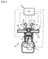
- FIG. 2 is a sectional view of a structure of one cylinder of the engine 100 in accordance with the embodiment.
- the engine 100 is a four-cylinder diesel engine installed in a vehicle, and each cylinder is equipped with a piston that defines a combustion chamber.
- the piston of each combustion chamber is slidably fitted into the cylinder, and is joined, through a connecting rod, to a crankshaft 21, which is an output shaft member.
- the engine ECU 10 determines a fuel injection amount and a fuel injection timing on the basis of information such as the intake air amount from an airflow meter 46 and the position of the piston from a crank angle sensor 41, and sends signals to the injector 17.
- the injector 17 injects fuel into the combustion chamber by the specified fuel injection amount at the specified injection timing.
- the fuel injected by the injector 17 is atomized and is formed into an air-fuel mixture with intake air that flows into the combustion chamber as the intake valve is opened.
- the air-fuel mixture is compressed in the combustion chamber by the piston ascending motion and is ignited and burned.
- the air-fuel mixture expands the combustion chamber, and moves the piston downwards.
- the descending motion is changed to the axial motion of the crankshaft 21 via the connecting rod. and the engine 100 obtains power.
- the engine 100 is not limited to four cylinders but may be a multi-cylinder diesel engine.
- the engine 100 is preferably a diesel engine that uses light oil as fuel, the engine 100 is not limited thereto.
- the engine 100 is an exemplary structure of the internal combustion engine of the present invention.
- the crank angle sensor 41 is provided in the vicinity of the crankshaft 21.
- the crank angle sensor 41 is configured to detect the rotation angle of the crankshaft 21 and send the result of detection to the engine ECU 10.
- the engine ECU 10 obtains information about the crank angle such as the rotation number and the angular velocity of the crankshaft 21 in operation.
- the engine ECU 10 calculates the engine speed and the engine torque on the basis of the obtained rotation speed and the angular velocity of the crankshaft 21, and recognizes the power of the engine 100.
- a water jacket in which cooling water is circulated is provided in the periphery of the combustion chamber of the engine 100, and is provided with the water temperature sensor 42 for measuring the temperature of the cooling water.
- the water temperature sensor 42 detects the temperature of the cooling water and sends the result of detection to the engine ECU 10.
- the engine ECU 10 recognizes the temperature of the cooling water of the engine 100.
- the water temperature sensor 42 may be provided in an arbitrary position where the temperature of the cooling water circulated in the engine 100 can be detected.
- the engine ECU 10 may recognize the cooling water temperature from another temperature detected such as the temperature of exhaust gas, or may estimate the cooling water temperature from the operation history of the engine 100.
- Each chamber is provided with a plurality of intake valves and a plurality of exhaust valves.
- FIG. 2 illustrates one of the intake valves and one of the exhaust valves.
- An intake valve 22 is arranged in each intake port of the combustion chamber, and an intake camshaft 24 for opening and closing the intake valve 22 is arranged.
- an exhaust valve 23 is arranged in each exhaust port of the combustion chamber, and an exhaust camshaft 25 for opening and closing the exhaust value 23 is arranged.
- the intake valve 22 and the exhaust valve 23 are opened and closed by rotations of the intake camshaft 24 and the exhaust camshaft 25 to which the rotation of the crankshaft 21 is transferred via a joint mechanism (for example, a timing belt or a timing chain), so that the intake port and the exhaust port communicate with or are isolated from the combustion chamber.
- a joint mechanism for example, a timing belt or a timing chain
- the intake camshaft 24 has an electric VVT mechanism 26, which is a variable valve timing mechanism (hereinafter, referred to as VVT mechanism).
- VVT mechanism rotates the intake camshaft 24 by an electric motor by instructions from the engine ECU 10.
- the rotational phase of the intake camshaft 24 with respect to the crankshaft 21 is changed, and the valve timing of the intake value 22 is thus changed.
- the rotational phase of the intake camshaft 24 is detected by an intake cam angle sensor 48, and is output to the engine ECU 10.
- the engine ECU 10 can obtain the phase of the intake camshaft 24 and the phase of the intake valve 22.
- the phase of the intake camshaft 24 is represented with reference to the crank angle.
- the exhaust camshaft 25 has a hydraulic VVT mechanism 27.
- the hydraulic VVT mechanism 27 rotates the exhaust camshaft 25 by an oil controlled valve (OCV) by instructions of the engine ECU 10.
- OCV oil controlled valve
- the rotational phase of the exhaust camshaft 25 with respect to the crankshaft 21 is changed, and the valve timing of the exhaust valve 23 is changed.
- the rotational phase of the exhaust camshaft 25 is detected by an exhaust cam angle sensor 49, and is output to the engine ECU 10.
- the engine ECU 10 can obtain the phase of the exhaust camshaft 25 and the phase of the exhaust valve 23.
- the phase of the exhaust camshaft 25 is represented with reference to the crank angle.
- the hydraulic VVT mechanism 27 adjusts OCV by instructions from the engine ECU 10 to thus open the exhaust valve 23 in the intake stroke of the engine 100.
- the hydraulic VVT mechanism 27 of the present embodiment is of hydraulic type, it may be of electric type like the intake camshaft 24.
- the hydraulic VVT mechanism 27 is an exemplary structure of variable valve timing means and variable phase changing means of the present invention.
- the engine 100 is equipped with a common rail type fuel injection system composed of the injector 17, a common rail 18, a low-pressure fuel and a high-pressure fuel pump. Fuel in a fuel tank sucked by the low-pressure fuel pump is discharged to and stored in the common rail 18 at high pressure by the high-pressure fuel pump.
- the common rail 18 is a container that stores high pressure fuel to be supplied to the injector 17. Fuel supplied by the high-pressure fuel pump at high pressure is accumulated in the common rail 18 until a pressure necessary for injection is available, and is supplied to the injector 17 attached to each combustion chamber via a high-pressure pipe.
- the common rail 18 is provided with a rail pressure sensor and a decompression valve.
- the engine ECU 10 instructs the decompression valve to open in a case where the fuel pressure in the common rail 18 indicated by the rail pressure sensor exceeds a specified value. Fuel is discharged by the decompression valve so that the common rail pressure is adjusted so as to be always equal to or lower than the specified value. Fuel discharged by the decompression valve returns to the fuel tank via a relief pipe.
- the injector 17 is arranged to each combustion chamber. Fuel supplied from the common rail 18 via the high-pressure pipe is injected in the combustion chamber in the engine cylinder by the injector 17 in response to the instructions by the engine ECU 10.
- the engine ECU 10 determines the fuel injection amount and the injection timing on the basis of information such as the intake air amount from the airflow meter 46 and the piston position from the crank angle sensor 41, and sends a signal to the injector 17.
- the injector 17 injects fuel into the fuel chamber at high pressure by the specified fuel injection amount at the specified injection timing. Leakage fuel of the injector 17 is returned to the fuel tank through the relief pipe.
- the injector 17 may be attached in an arbitrary position based on the specifications of the engine 100.
- An intake manifold 11 is connected to each combustion chamber of the engine 100 so as to communicate therewith.
- the intake manifold 11 is connected, through an intake passage 12, to an air cleaner via the airflow meter 46, a diesel throttle 19, an intercooler, and a compressor of the turbocharger 14, and introduces intake air from the outside of the engine 100 into each combustion chamber.
- a throttle position sensor 47 is provided to the diesel throttle 19.
- the airflow meter 46 and the throttle position sensor 47 detect the amount of intake air that passes through the intake passage 12 and the valve opening of the diesel throttle 19, respectively, and sends the detection results to the engine ECU 10.
- the engine ECU 10 recognizes the amount of intake air introduced into the intake manifold 11 on the basis of the detection results sent, and adjusts the valve opening of the diesel throttle 19 so that intake air needed to operate the engine 100 can be introduced into the combustion chamber.
- the diesel throttle 19 is preferably of throttle-by-wire type using a stepping motor, another arbitrary mechanism capable of changing the valve opening of the diesel throttle 19 may be applied.
- the exhaust manifold 13 is connected to each combustion chamber of the engine 100 so as to communicate therewith.
- the exhaust manifold 13 is joined, through an exhaust passage 15, to an exhaust emission control device 30 via an exhaust turbine of the turbocharger 14, and discharges exhaust gas after burning to the outside.
- the turbocharger 14 uses the kinetic energy of exhaust gas to rotate the exhaust turbine, compresses the intake air passing through the air cleaner and supplies the compressed intake air to the intercooler.
- the compressed intake air is cooled by the intercooler, and is introduced into the intake manifold 11.
- the turbocharger 14 is a variable nozzle turbocharger (hereinafter, abbreviated as VNT), and a variable nozzle vane mechanism 141 is provided on the exhaust turbine side thereof.
- VNT variable nozzle turbocharger
- the angle at which the exhaust gas flows in turbine impeller vanes is controlled to adjust the supercharging pressure of the intake air introduced into the intake manifold. For example, when the opening of the variable nozzle vane mechanism 141 is reduced, a larger amount of exhaust gas flows in the turbine impeller vanes, so that the ratio of using the energy of exhaust gas can be increased and the supercharging efficiency can be improved.
- the turbocharger 14 is not limited to VNT but may be configured to adjust the supercharging pressure by a waste gate (control of efficiency of using the energy of exhaust gas).
- the turbocharger 14 is an exemplary structure of a supercharger of the present invention.
- the variable nozzle vane mechanism 141 is an exemplary structure of supercharging efficiency control means of the present invention.
- the exhaust emission control device 30 cleans the exhaust gas of the engine 100, and has a cleaning catalyst 31 that removes NOx, HC and CO in the exhaust gas, and a DPF 32 that captures particle materials (PM) such as soot.
- DPNR Diesel Particulate NOx Reduction system
- NOx absorber catalyst is incorporated into a particulate filter may be applied to the exhaust emission control device 30.
- an A/F sensor 45 that detects the air-fuel ratio of the engine 100 and the exhaust temperature sensor 43 that detects the temperature of exhaust gas.
- the engine ECU 10 is capable of recognizing the air-fuel ratio of the engine 100 and the exhaust gas temperature under various load conditions.
- the exhaust manifold 13 communicates with the intake manifold 11 through the EGR passage 16.
- the exhaust gas that flows into the EGR passage 16 is cooled by the EGR cooler 161, and moves to the intake manifold 11 while the flow rate of the exhaust gas is adjusted by an EGR valve 162. Then, the exhaust gas is introduced into the combustion chamber along with the intake air.
- the EGR valve 162 appropriately adjusts the amount of recirculation of the exhaust gas back to the intake manifold 11 by adjusting the valve opening in accordance with an instruction by the engine ECU 10.
- the EGR passage 16, the EGR cooler 161 and the EGR valve 162 function as an external EGR that recirculates a portion of the exhaust gas passing through the exhaust manifold 13 back to the intake manifold 11.
- the EGR passage 16 is an exemplary structure of the exhaust gas recirculation passage of the present invention.
- the shut-off valve 163 is provided in a connecting portion between the exhaust manifold 13 and the EGR passage 16, that is, an exhaust gas inlet portion of the EGR passage 16.
- the shut-off valve 163 is configured to isolate the EGR passage 16 from the exhaust manifold 13 in accordance with an instruction by the engine ECU 10. By isolating the EGR passage 16 from the exhaust manifold 13 by the shut-off valve 163, it is possible to reduce the capacity of the exhaust system of the engine 100 (the sum of at least the capacity of the exhaust manifold 13 and that of the EGR passage 16) by the capacity of the EGR passage 16.
- shut-off valve 163 By opening the shut-off valve 163 to open the EGR passage 16, it is possible to increase the capacity of the exhaust system of the engine 100 by the capacity of the EGR passage 16.
- the shut-off valve 163 may be provided in an arbitrary position in the EGR passage 16, it is possible to change the capacity of the exhaust system of the engine 100 more greatly by providing the shut-off valve 163 to the exhaust gas inlet portion of the EGR passage 16.
- the shut-off valve 163 is an exemplary structure of an exhaust system capacity changing means of the present invention.
- the atmospheric pressure sensor 44 detects the atmospheric pressure of the outside of the vehicle on which the engine 100 is mounted, and sends the result of detection to the engine ECU 10.
- the engine ECU 10 recognizes the atmospheric pressure of the outside of the vehicle.
- the engine ECU 10 is a computer equipped with a CPU (Central Processing Unit) that carries out operations, a ROM (Read Only Memory) that stores programs and the like, a RAM (Random Access Memory) and an NVRAM (Non Volatile RAM), which RAMS store data and the like.
- the engine ECU 10 reads the results of detection by the multiple sensors arranged in portions of the engine 100, and integrally controls the operation of the engine 100 on the basis of the detection results.
- the engine ECU 10 carries out a control (internal EGR) of adjusting the hydraulic VVT mechanism 27, the shut-off valve 163 and the variable nozzle vane mechanism 141 in accordance with the operating condition of the engine 100 and introducing the exhaust gas into the combustion chamber of the engine 100.
- the control of the internal EGR carried out by the engine ECU 10 is described below.
- the engine ECU 10 determines whether there is a request for execution of the internal EGR of the engine 100 on the basis of the received detection results of the water temperature sensor 42, the exhaust temperature sensor 43 and the atmospheric pressure sensor 44. More particularly, the engine ECU 10 determines that there is a request for execution of the internal EGR in a case where the temperature of the cooling water detected by the water temperature sensor 42 is lower than a predetermined temperature (for example, 50°C) that makes it possible to conclude that the engine 100 is in cold operation.
- a predetermined temperature for example, 50°C
- the engine ECU 10 determines that there is a request for execution of the internal EGR in a case where the temperature of the exhaust gas detected by the exhaust temperature sensor 43 is lower than a predetermined temperature (for example, 50°C that makes it possible to conclude that the exhaust gas is at low temperature.
- the engine ECU 10 determines that there is a request for execution of the internal EGR in a case where the atmospheric pressure of the outside detected by the atmospheric pressure sensor 44 is lower than a predetermined atmospheric (for example, 900 hPa) that makes it possible to conclude that the vehicle on which the engine 100 is mounted is in a high attitude.
- the temperature of the exhaust gas is relatively low, whereby introduction of the exhaust gas that passes through the EGR passage 16 and is cooled into the combustion chamber (external EGR) may lower the combustion temperature excessively and may degrade combustion performance.
- the atmospheric pressure of the outside of the engine 100 is low, a smaller amount of oxygen than the normal amount is introduced into the combustion chamber, whereby introduction of the external EGR having a lomer temperature into the combustion chamber may cause shortage of oxygen and may degrade combustion performance.
- the engine ECU 10 may recognize the exhaust gas temperature of the engine 100 on the basis of the power of the engine 100 calculated by the detection results of the crank angle sensor 41.
- the engine ECU 10 determines that there is a request for execution of the internal EGR of the engine 100, the engine ECU 10 instructs the hydraulic VVT mechanism 27 to open the exhaust valve 23 of the engine 100 in the intake stroke in addition to the valve opening operation in the exhaust stroke, so that a portion of the exhaust gas that flows out to the exhaust side can be introduced into the combustion chamber.
- FIG. 3 indicates an exemplary pressure behavior and an exemplary valve lift on the exhaust side of the engine 100.
- FIG. 3 indicates a behavior ot a four-cylinder engine as an example of the multi-cylinder engine.
- the engine ECU 10 determines whether the amount of exhaust gas actually introduced into the combustion chamber of the engine 100 (internal EGR) is smaller than a target introduction amount.
- internal EGR the amount of exhaust gas actually introduced into the combustion chamber of the engine 100
- a correlation map of the supercharging pressure and the amount of gas in the cylinder may be prepared for each output of the engine 100 and may be stored in the ROM of the engine ECU 10 beforehand, whereby it is possible to quickly and properly determine whether the amount of internal EGR actually introduced is smaller than the target introduction amount.
- the engine ECU 10 determines that the amount of internal EGR actually introduced is not smaller than the target introduction amount (equal to or larger than the target introduction amount)
- the engine ECU 10 instructs the variable nozzle vane mechanism 141 to increase the opening, and thereby decreases the supercharging efficiency of the turbocharger 14.
- the amount of exhaust gas that flows into the turbine impeller vanes is reduced, so that the resistance to the flow of the exhaust gas in the engine 100 can be reduced and the pressure on the exhaust side can be lowered. It is therefore possible to reduce the amount of the internal EGR introduced into the combustion chamber when the exhaust valve 23 is opened in the intake stroke.
- the engine ECU 10 executes the control of keeping a greater opening of the variable nozzle vane mechanism 141 until the amount of internal EGR actually introduced reaches the target introduction amount.
- the engine ECU 10 determines that the amount of internal EGR actually introduced is smaller than the target introduction amount. the engine ECU 10 instructs the shut-off valve 163 to shut off the EGR passage 16 to reduce the capacity of the exhaust system of the engine 100.
- a reduced capacity of the exhaust system of the engine 100 reduces the capacity of the passage through which the exhaust gas can pass, and thus increases the amplitude of exhaust pulsation (see FIG. 3 ).
- the increased amplitude of exhaust pulsation increases the amount of the internal EGR introduced into the combustion chamber when the exhaust valve 23 is opened in the intake stroke. Even when the EGR passage 16 is shut off while the engine 100 is in operation, the fuel economy is not degraded. It is therefore possible to increase the amount of the internal EGR introduced into the combustion chamber without degrading the fuel economy by shutting off the EGR passage 16 to thus reduce the capacity of the exhaust system.
- the engine ECU 10 determines whether the amount of internal EGR actually introduced into the combustion chamber of the engine 100 is smaller than the target introduction amount.
- the engine ECU 10 determines that the amount of internal EGR actually introduced is smaller than the target introduction amount (equal to or larger than the target introduction amount)
- the engine ECU 10 instructs the variable nozzle vane mechanism 141 to increase the opening to thereby lower the supercharging efficiency of the turbocharger 14, as has been described previously.
- the engine ECU 10 determines that the amount of internal EGR actually introduced is smaller than the target introduction amount, the engine ECU 10 instructs the hydraulic VVT mechanism 27 to advance the opening or closing phase of the exhaust valve 23 (see FIG. 3 ).
- the rise of pressure on the exhaust side of the engine 100 is determined by the engine speed and the opening timing of the exhaust valve, the pressure on the exhaust side becomes higher as the opening timing of the exhaust valve 23 is earlier for an identical engine speed.
- the closing phase of the exhaust valve 23 in the exhaust stroke earlier than the present state it is possible to increase the pressure on the exhaust side and increase the amount of internal EGR introduced in the combustion chamber when the exhaust valve 23 is opened in the intake stroke.
- the angle of closing the exhaust valve 23 it is possible to confine the exhaust gas (internal EGR) in the combustion chamber and suppress the exhaust gas from flowing out to the exhaust side.
- the fuel economy is not degraded greatly by setting the phases of opening and closing the exhaust valve 23 earlier than the present states while the engine 100 is in operation.
- the advanced phase angle ot the exhaust valve 23 may be determined beforehand on the basis of a correlation map between the power of the engine 100 and the advanced angle amount created by a bench test or the like.
- the engine ECU 10 determines whether the amount of internal EGR actually introduced into the combustion chamber of the engine 100 is smaller than the target introduction amount. When the engine ECU 10 determines that the amount of internal EGR actually introduced is not smaller than the target introduction amount (equal to or larger than the target introduction amount), the engine ECU 10 instructs the variable nozzle vane mechanism 141 to increase the opening and thus reduce the supercharging efficiency of the turbocharger 14, as has been described previously.
- the engine ECU 10 determines that the amount of internal EGR actually introduced is smaller than the target introduction amount, the engine ECU 10 instructs the variable nozzle vane mechanism 141 to reduce the opening and thus improve the supercharging efficiency of the turbocharger 14.
- a reduced opening of the variable nozzle vane mechanism 141 causes a larger amount of exhaust gas to flow in the turbine impeller vanes, whereby the resistance to the flow of the exhaust gas of the engine is increased and the pressure on the exhaust side is raised. It is thus possible to increase the amount of internal EGR introduced into the combustion chamber when the exhaust valve 23 is opened in the intake stroke.
- the opening of the variable nozzle vane mechanism 141 is reduced while the engine 100 is in operation, the pumping loss is increased and the fuel economy is degraded. Since the present embodiment realizes a condition that the amount of internal EGR is increased and is close to the target introduction amount by the aforementioned two controls, it is possible to further reduce the degree of change of opening of the variable nozzle vane mechanism 141. That is, by executing the controls, the engine ECU 10 is capable of keeping the degradation of fuel economy of the engine 100 to a minimum and appropriately controlling the amount of exhaust gas introduced into the combustion chamber by the internal EGR.
- the engine ECU 10 repeats the above control until the amount of internal EGR actually introduced into the combustion chamber reaches the target introduction amount.
- the engine ECU 10 is an exemplary structure of variable valve means, phase changing means, exhaust system capacity changing means and supercharging efficiency control means.
- the engine system 1 of the present embodiment adjusts the hydraulic VVT mechanism 27, the shut-off valve 163 and the variable nozzle vane mechanism 141 in accordance with the driving condition of the engine 100, and thereby controls the amount of internal EGR introduced into the combustion chamber of the engine 100 appropriately.
- the engine system I of the present embodiment executes control to shut off the EGR passage 16, which control has the smallest influence on the fuel economy, and thereby increases the amount of internal EGR introduced.
- the engine system 1 executes control to advance the phase of the exhaust valve 23, which control has a small influence on the fuel economy, and thereafter, executes control to reduce the opening of the variable nozzle vane mechanism 141. That is, by preferentially executing the control that has a small influence on the fuel economy, it is possible to suppress the degradation of fuel economy of the engine 100 to a minimum and increase the amount ot internal EGR introduced into the combustion chamber.
- FIG. 4 is a flowchart of an exemplary process of the engine ECU 10.
- the engine system 1 of the present embodiment is equipped with the hydraulic VVT mechanism 27, the shut-off valve 163 and the variable nozzle vane mechanism 141, and the engine ECU 10 executes control to adjust the hydraulic VVT mechanism 27, the shut-off valve 163 and the variable nozzle vane mechanism 141 in accordance with the operating condition of the engine 110 and to thereby adjust the amount of internal EGR introduced into the combustion chamber.
- the control of the engine ECU 10 is initiated when the ignition switch is switched ON and the engine 100 is started, and the following control is repeatedly carried out while the engine 100 is in operation. Further, the engine ECU 10 always the results of detection by the water temperature sensor 42, the exhaust temperature sensor 43 and the atmospheric pressure sensor 44 while the control is being processed.
- step S1 the engine ECU 10 determines whether there is a request for execution of the internal EGR of the engine 100 on the basis of the received detection results of the water temperature sensor 42, the exhaust temperature sensor 43 and the atmospheric pressure sensor 44. Since the concrete method for determination has been described previously, a detailed description thereof is omitted here.
- step S1/NO the engine ECU 10 ends the control process.
- step S1/YES the engine ECU 10 proceeds to next step S2.
- step S2 the engine ECU 10 instructs the hydraulic VVT mechanism 27 to open the exhaust valve 23 of the engine 100 in the intake stroke besides the valve opening operation in the exhaust stroke, so that a portion of the exhaust gas discharged to the exhaust side can be introduced into the combustion chamber.
- step S3 the engine ECU 10 determines whether the amount of internal EGR actually introduced in the combustion chamber of the engine, 100 is smaller than the target introduction amount. Since the concrete method for determination has been described previously, a detailed description is omitted here.
- step S3/NO the engine ECU 10 proceeds to step S9.
- step S3/YES the engine ECU 10 proceeds to step S4.
- step S4 the engine ECU 10 instructs the shut-off valve 163 to shut off the EGR passage 16 to reduce the exhaust-system capacity of the engine 100 and increase the pressure on the exhaust side.
- step S4 the engine ECU 10 proceeds to next step S5.
- step S5 the engine ECU 10 determines whether the amount of internal EGR actually introduced in the combustion chamber of the engine after the process of step S4 is smaller than the target introduction amount.
- step S5/NO the engine ECU 10 proceeds with step S9.
- step S5/YES the engine ECU 10 proceeds to next step S6.
- step S6 the engine ECU 10 instructs the hydraulic VVT mechanism 27 to advance the angles of the phases of opening and closing the exhaust valve 23 from the current states, and thereby increases the pressure on the exhaust side while suppressing discharge of internal EGR from the combustion chamber.
- the engine ECU 10 ends the process of step S6, and proceeds to next step S7.
- step S7 the engine ECU 10 determines whether the amount of internal EGR introduced into the combustion chamber of the engine 100 after the process of step S6 is smaller than the target introduction amount.
- the engine ECU 10 proceeds to step S9.
- the engine ECU proceeds to step S8.
- step S8 the engine ECU 10 instructs the variable nozzle vane mechanism 141 to reduce the opening and to thereby improve the supercharging efficiency of the turbocharger 14 and increase the pressure on the exhaust side.
- the engine ECU 10 ends the process after finishing the process of step S8.
- step S9 the engine ECU 10 instructs the variable nozzle vane mechanism 141 to increase the opening and to thereby reduce the supercharging efficiency of the turbocharger 14 and reduce the pressure on the exhaust side.
- the engine ECU 10 ends the control process after finishing the process of step S9.
- the engine system of the present invention includes an engine ECU, a hydraulic VVT mechanism configured to be able to open an exhaust valve of an engine in an intake stroke besides a valve opening operation in an exhaust stroke and to change phases of opening and closing the exhaust valve, a shut-off valve capable of shutting off an EGR passage communicating with an exhaust manifold, and a variable nozzle vane mechanism controlling a supercharging efficiency of a turbocharger, and adjusts the hydraulic VVT mechanism, the shut-off valve and the variable nozzle vane mechanism on the basis of an operating condition of the engine, so that the amount of internal EGR introduced into a combustion chamber of the engine can be controlled appropriately.
- the engine system of the present embodiment preferentially executes control that has a negative influence on the fuel economy in a case where the amount of internal EGR actually introduced into the combustion chamber is smaller than the target introduction amount, and is thus capable of suppressing the degradation of fuel economy to a minimum and increasing the amount of internal EGR into the combustion chamber.
- An engine system 2 of the present embodiment differs from the engine system 1 in that the engine system 2 executes, in addition to the control of the embodiment I, scavenging control to open the exhaust valve when the pressure on the exhaust side becomes lower than the pressure on the intake side in an operating range in which it is not requested to execute the internal EGR of the engine.
- the engine system 2 of the present embodiment executes control to adjust the hydraulic VVT mechanism 27, the shut-off valve 163 and the variable nozzle vane mechanism 141 on the basis of the operating condition of the engine 100 and to thereby open the exhaust valve 23 at a timing when the pressure on the exhaust side becomes lower than the pressure on the intake side and scavenge the exhaust gas in the combustion chamber (scavenging control).
- scavenging control executed by the engine ECU 10 is described.
- the engine ECU 10 determines whether there is a request for execution of the scavenging control of the engine 100 on the basis of the received result of detection of the crank angle sensor 41. More specifically, the engine ECU 10 determines that there is a request for execution of the scavenging control in a case where the crank angle acceleration detected by the crank angle sensor 41 is equal to or larger than a predetermined angular acceleration that makes it possible to conclude that the vehicle with the engine 100 being mounted is in an accelerated state or a climbing state. In this case, the engine ECU 10 is not limited to the information sent from the crank angle sensor 41, but may determine a request for execution of scavenging control on the basis of another information such as information about an operation of the acceleration pedal by the driver.
- the engine ECU 10 determines that there is a request for execution of the scavenging control of the engine 100, the engine ECU 10 instructs the hydraulic VVT mechanism 27 to retard the closing phase of the exhaust valve 23 in the exhaust stroke of the engine 100 beyond the phase of the top dead center of the piston.
- FIG. 5 indicates an exemplary pressure behavior and an exemplary valve lift on the exhaust side of the engine 100.
- FIG. 5 indicates a behavior of a four-cylinder engine as an example of the multi-cylinder engine.
- the closing phase of the exhaust valve 23 advances beyond the top dead center of the piston, that is, when the exhaust valve 23 is opened while the piston is ascending, all of the exhaust gas (internal EGR) in the combustion chamber is not discharged but some exhaust gas remains.
- the engine ECU instructs the shut-off valve 163 to shut off the EGR passage 16 and further reduce the exhaust-system capacity of the engine 100.
- the engine ECU 10 determines whether the scavenging control of the engine 100 is executable. More particularly, the engine ECU 10 determines that the scavenging control of the engine 100 is executable in a case where the pressure on the exhaust side is lower than the pressure on the intake side in the intake stroke of the engine 100. In this case, it is possible to quickly and appropriately determine whether the scavenging control is executable by referring to, for example, the difference in pressure between the intake pressure and the exhaust pressure and the amplitude of exhaust pulsation.
- the engine ECU 10 determines that the scavenging control is executable, the engine ECU 10 instructs the hydraulic VVT mechanism 27 to open the exhaust valve 23 of the engine 100 in the intake stroke besides the valve opening operation in the exhaust stroke in order to execute the scavenging control (see FIG. 5 ).
- the exhaust gas (internal EGR) that remains in the combustion camber is discharged to the exhaust side by utilizing the pressure difference between the exhaust side and the intake side, whereby the amount of intake air introduced into the chamber of the engine 100 can be increased.
- the engine ECU 10 determines whether the real supercharging pressure of the turbocharger 14 is higher than the target supercharging pressure by not less than a predetermined value. It is noted that the state in which the real supercharging pressure is higher than the target supercharging pressure by not less than the predetermined value is a state in which there is a sufficient room to reduce the real supercharging pressure of the turbocharger 14, that is, there is a sufficient room to reduce the pressure on the exhaust side of the engine 100.
- the engine ECU 10 determines that there is not a sufficient room to reduce the pressure on the exhaust side in a case where the real supercharging pressure of the turbocharger 14 is not higher than the target supercharging pressure by not less than the predetermined value. Then, the engine ECU 10 determines that the execution of the scavenging control of the engine 100 is impossible, and terminates the control process.
- the engine ECU 10 determines that there is a sufficient room to reduce the pressure on the exhaust side. Then, the engine ECU 10 instructs the variable nozzle vane mechanism 141 to increase the opening and thereby reduce the supercharging efficiency of the turbocharger 14.
- the scavenging control of the engine 100 may be executed more frequently by further increasing the opening of the variable nozzle vane mechanism 141.
- the engine ECU 10 determines whether the scavenging control of the engine 100 is executable.
- the engine ECU 10 instructs the hydraulic VVT mechanism 27 to open the exhaust valve 23 of the engine 100 in the intake stroke besides the valve opening operation in the exhaust stroke, whereby the exhaust gas (internal EGR) that remains in the combustion chamber is discharged to the exhaust side.
- the engine ECU 10 determines that the execution of the scavenging control is impossible, the engine ECU 10 terminates the control process.
- the engine system 2 of the present embodiment adjusts the hydraulic VVT mechanism 27, the shut-off valve 163 and the variable nozzle vane mechanism 141 on the basis of the operating condition of the engine 100, so that the exhaust valve 23 can be opened at a timing when the pressure on the exhaust side becomes lower than the pressure on the intake side.
- the exhaust gas (internal EGR) that remains in the combustion chamber can be appropriately discharged to the exhaust side by utilizing the pressure difference between the exhaust side and the intake side, and the amount of intake air introduced in the combustion chamber can be increased.
- the engine system 2 of the present embodintent is capable of further increasing the opening of the variable nozzle vane mechanism 141 and thus reducing the pressure on the exhaust side in a case where the real supercharging pressure of the turbocharger 14 is higher than the target supercharging pressure by not less than the predetermined value. It is thus possible to make the pressure on the exhaust side lower than the pressure on the intake side more frequently and to execute the scavenging control of the engine 100 more frequently.
- FIG. 6 is a flowchart of an example of the process of the engine ECU 10.
- the engine system of the present embodiment is configured so that the engine ECU 10 executes a control, (scavenging control) to adjust the hydraulic VVT mechanism 27, the shut-off valve 163 and the variable nozzle vane mechanism 141 on the basis of the operating condition of the engine 100 and to open the exhaust valve 23 at a timing when the pressure on the exhaust side becomes lower than the pressure on the intake side.
- a control (scavenging control) to adjust the hydraulic VVT mechanism 27, the shut-off valve 163 and the variable nozzle vane mechanism 141 on the basis of the operating condition of the engine 100 and to open the exhaust valve 23 at a timing when the pressure on the exhaust side becomes lower than the pressure on the intake side.
- the control of the engine ECU 10 is initiated when the ignition switch is switched ON and the engine 100 is started, and the following control process is repeatedly carried out when the engine 100 is in operation.
- the engine ECU 10 always receives the results of detection by the crank angle sensor 41 while the control process is being performed.
- step S 10 the engine ECU 10 determines whether there is a request for execution of the scavenging control of the engine 100 on the basis of the received detection results of the crank angle sensor 41.
- the concrete method for determination has been described previously, and a detailed description thereof is omitted here.
- step S10/NO the engine ECU 10 ends the control process.
- step S 10/YES the engine ECU 10 proceeds to the next step S11.
- step S11 the engine ECU 10 instructs the hydraulic VVT mechanism 27 to retard the closing phase of the exhaust valve 23 in the exhaust stroke of the engine 100 beyond the top dead point of the piston and to thus reduce the residue of the exhaust gas (internal EGR) in the combustion chamber.
- the engine ECU 10 proceeds to step S12 after finishing the process of step S11.
- step S12 the engine ECU 10 instructs the shut-off valve 163 to shut off the EGR passage 16 so as to further reduce the capacity of the exhaust system of the engine 100 and strengthen the exhaust pulsation, and thus raise the supercharging pressure of the turbocharger 14.
- the engine ECU 10 proceeds to step S13 after finishing the process of step S12.
- step S 13 the engine ECU 10 determines whether the scavenging control of the engine 100 is executable. Since the concrete method for execution has been described previously, a detailed description thereof is omitted here. In a case where the scavenging control is executable (step S13/YES), the engine ECU 10 proceeds to step S18. In a case where the scavenging control is not executable (impossible) (step S13/NO), the engine ECU 10 proceeds to the next step S14.
- step S14 the engine ECU 10 determines whether the real supercharging pressure of the turbocharger 14 is higher than the target supercharging pressure by not less than the predetermined value. Since the state in which the real supercharging pressure is higher than the target supercharging pressure by not less than the predetermined value has described previously, a detailed description thereof is omitted. In a case where the real supercharging pressure is not larger than the target supercharging pressure by not less than the predetermined value (step S14/NO), the engine ECU 10 determines that there is no sufficient room to reduce the pressure on the exhaust side, and proceeds to step S17.
- step S14/YES the engine ECU 10 determines that there is a sufficient room to reduce the pressure on the exhaust side, and proceeds to the next step S15.
- step S 15 the engine ECU 10 instructs the variable nozzle vane mechanism 141 to increase the opening so as to reduce the supercharging efficiency of the turbocharger 14 and reduce the pressure on the exhaust side.
- the engine ECU 10 proceeds to the next step S16 after finishing the process of step S15.
- step S16 the engine ECU 10 determines whether the scavenging control of the engine 100 is executable. In a case where the scavenging control is executable (step S16/YES), the engine EC U 10 proceeds to step S18. In a case where the scavenging control is not executable (impossible) (step 16/NO), the engine ECU 10 proceeds to the next step S17.
- step S 17 the engine ECU 10 determines that there is no timing when the pressure in the exhaust side is lower than the pressure in the intake side in the intake stroke of the engine 100, and ends the control.
- step S18 the engine ECU 10 instructs the hydraulic VVT mechanism 27 to open the exhaust valve 23 of the engine 100 in the intake stroke besides the valve opening operation in the exhaust stroke so as to discharge the exhaust gas (internal EGR) that remains in the combustion chamber by utilizing the pressure difference between the exhaust side and the intake side.
- the engine ECU 10 ends the control process after finishing the process of step S 18.
- the engine system of the present embodiment is configured so that the hydraulic VVT mechanism executes the control to retard the closing phase of the exhaust valve in the exhaust stroke beyond the phase of the top dead center of the piston and executes the control to shut off the EGR passage 16 by the shut-off valve. Then, the hydraulic VVT mechanism opens the exhaust value in the intake stroke besides in the valve opening operation in the intake stroke, so that the exhaust gas (internal EGR) that remains in the combustion chamber of the engine is discharged to the exhaust side by utilizing the pressure difference between the exhaust side and the intake side. It is thus possible to increase the amount of intake air introduced into the combustion chamber in an operation range in which it is not requested to execute the internal EGR of the engine 100.
- the engine system of the present embodiment is configured so that the hydraulic VVT mechanism executes the control of retarding the closing phase of the exhaust valve, and is capable of reducing the pressure on the exhaust side by reducing the supercharging efficiency of the turbocharger when the supercharging pressure of the turbocharger after execution of the control to shut off the EGR passage 16 by the shut-off valve is higher than the garget supercharging pressure by not less than the predetermined value.
- the hydraulic VVT mechanism executes the control of retarding the closing phase of the exhaust valve, and is capable of reducing the pressure on the exhaust side by reducing the supercharging efficiency of the turbocharger when the supercharging pressure of the turbocharger after execution of the control to shut off the EGR passage 16 by the shut-off valve is higher than the garget supercharging pressure by not less than the predetermined value.
- means for changing the exhaust-system capacity of the internal combustion engine is not limited to the open/close control of the EGR passage.
- a structure may be employed in which a sub chamber having a predetermined capacity is provided in the exhaust manifold, and the exhaust-system capacity is changed by controlling the communication between the exhaust manifold and the sub chamber.
- Another structure capable of changing the exhaust-system capacity may be employed.
Abstract
Description
- The present invention relates to a control device of an internal combustion engine.
- In internal combustion engines (particularly, diesel engine), there is known an art of an exhaust gas recirculation (EGR) in which a portion of an exhaust gas is recirculated back to a combustion chamber in order to reduce the amount of nitrogen oxide (NOx) exhausted from the combustion chamber. As a method of implementing EGR, there is well known a technique of providing an EGR passage through which an exhaust passage and an intake passage of an internal combustion engine communicate with each other and introducing a portion of an exhaust gas that flows through the exhaust passage into the intake passage (hereinafter, the above technique is referred to as external EGR).
- As another implementation method of EGR, there is a technique of utilizing a burned gas in the previous cycle (hereinafter, this technique is referred to as internal EGR). As an art of the internal combustion engine that performs the internal EGR, Patent Document I discloses a technique of opening an exhaust valve in the intake stroke of the internal combustion engine to recirculate a portion of the burned gas (exhaust gas) back to the combustion chamber.
Patent Document 2 discloses a technique of varying a negative valve overlap period during which the intake valve and the exhaust valve of the internal combustion engine are both closed to thereby control the internal EGR amount. -
- PATENT DOCUMENT 1: Japanese Patent Application Publication No.
2006-144713 - PATENT DOCUMENT 2: Japanese Patent Application Publication No.
2007-303355 - The amount of exhaust gas introduced into the combustion chamber by the internal EGR changes due to the pressure balance between the intake side and the exhaust side of the internal combustion engine. Particularly, exhaust pulsation in which the pressure on the exhaust side varies periodically takes place in the internal combustion engine. Thus, if the internal EGR control is performed without considering the pressure difference between the intake side and the exhaust side, the real recirculation amount of exhaust gas may greatly differ from the target recirculation amount.
- In an operating range in which the execution of the internal EGR is not requested, it is desirable that the burned gas is exhausted to the exhaust side from the combustion chamber as much as possible. In such an operating range of the internal combustion engine, the exhaust valve is opened at a timing when the pressure on the exhaust side is lower than the pressure on the intake side due to exhaust pulsation, so that the burned gas in the combustion chamber can be scavenged and an increased amount of intake air can be introduced. Similarly, in the above scavenging control, if the exhaust valve is opened without considering the pressure difference between the intake side and the exhaust side, the sufficient scavenging effect may not be obtained.
- The present invention was made from the above viewpoints, and has an object of providing a control device of an internal combustion engine capable of appropriately controlling the amount of exhaust gas introduced into the combustion chamber by the internal EGR.
- In order to achieve the above object, a control device of an internal combustion engine of the present invention is characterized by comprising: a variable valve means capable of opening an exhaust valve of an internal combustion engine in an exhaust stroke besides a valve opening operation in an intake stroke; a phase changing means changing phases of opening and closing the exhaust valve; an exhaust-system capacity changing means capable of changing an exhaust-system capacity that is a sum of a capacity of an exhaust manifold of the internal combustion engine and a space communicating with the exhaust manifold; and a supercharging efficiency control means controlling a supercharging efficiency of a supercharger supercharging intake air by utilizing energy of exhaust gas of the internal combustion engine.
- By having the variable valve means, the phase changing means and the exhaust-system capacity changing means as described above, it is possible to appropriately control the amount of exhaust gas introduced into the combustion chamber by the internal EGR.
- Particularly, the control device of the internal combustion engine of the present invention may be structured so that the variable valve means executes a control to open the exhaust vale of the internal combustion engine in the intake stroke besides the valve opening operation in the exhaust stroke and to introduce, into the internal combustion chamber, a portion of the exhaust gas flowing out to an exhaust side of the internal combustion engine from the combustion chamber, and the exhaust-system capacity changing means reduces the exhaust-system capacity in a case where an amount of exhaust gas introduced into the combustion chamber by the control of the variable valve means is smaller than a target introduction amount.
- It is known that exhaust pulsation is more conspicuous as the exhaust-system capacity becomes smaller, that is, the pressure on the exhaust side becomes higher. Thus, with the above structure, by reducing the exhaust-system capacity of the internal combustion engine and thereby raising the pressure on the exhaust side, it is possible to increase the amount of exhaust gas introduced into the combustion chamber without degrading fuel economy. It is thus possible to appropriately control the amount of exhaust gas introduced into the combustion chamber by the internal EGR.
- Also, the control device of the internal combustion engine of the present invention may be structured so that, in a case where the amount of exhaust gas introduced the combustion chamber after the control of the exhaust-system capacity changing means is executed is smaller than the target introduction amount, the phase changing means executes a control to advance phases of opening and closing the exhaust valve.
- With the above structure, the opening phase of the exhaust valve is advanced to raise the pressure on the exhaust side and to confine the exhaust gas in the combustion chamber, so that the amount of exhaust gas introduced into the combustion chamber can be increased without suppressing degradation of fuel economy. It is thus possible to appropriately control the amount of exhaust gas introduced into the combustion chamber by the internal EGR.
- Further, the control device of the internal combustion engine of the present invention may be structured so that, in a case where the amount of exhaust gas introduced into the combustion chamber after the control of the phase changing means is executed is smaller than the target introduction amount, the supercharging efficiency control means executes a control to improve the supercharging efficiency of the supercharger.
- With the above structure, the supercharging efficiency of the supercharger is improved to raise the pressure on the exhaust side, and the amount of exhaust gas introduced into the combustion chamber can be increased It is thus possible to appropriately control the amount of exhaust gas introduced into the combustion chamber by the internal EGR.
- Furthermore, the control device of the internal combustion engine of the present invention may be structured so that, that in a case where the amount of exhaust gas introduced into the combustion chamber by the control of the variable valve means exceeds the target introduction amount, the supercharging efficiency control means executes a control to reduce the supercharging efficiency of the supercharger.
- With the above structure, the supercharging efficiency of the supercharger is reduced to lower the pressure on the exhaust side, and the amount of exhaust gas introduced into the combustion chamber can be reduced. It is thus possible to appropriately control the amount of exhaust gas introduced into the combustion chamber by the internal EGR.
- Also, the control device of the internal combustion engine of the present invention may be structured so that that the phase changing means executes a control to retard a closing phase of the exhaust valve in an exhaust stroke of the internal combustion engine beyond a phase of a top dead center of a piston, and the exhaust-system capacity changing means executes a control to reduce the exhaust-system capacity in accordance with an operating condition of the internal combustion engine, and after the control of the phase changing means and the exhaust-system capacity changing means are executed, the variable valve means executes a control opens the exhaust valve of the internal combustion engine in an intake stroke besides a valve opening operation in an intake stroke and to discharge exhaust gas that remains in the combustion chamber of the internal combustion chamber to the exhaust side.
- With the above structure, since the exhaust valve can be opened when the pressure on the exhaust side becomes lower than the pressure on the intake side in an operating range in which it is not requested to execute the internal EGR, it is possible to scavenge the burned gas in the combustion chamber appropriately.
- Further, the control device of the internal combustion engine of the present invention may be structured so that, that in a case where the supercharging pressure of the supercharger after the control of the phase changing means and the control of the exhaust-system capacity changing means are executed is larger than a target introduction amount by not less than a predetermined value, the supercharging efficiency control means executes a control to reduce the supercharging efficiency of the supercharger.
- With the above structure, by reducing the supercharging efficiency of the supercharger to thus reduce the pressure on the exhaust side in a case where the supercharging pressure of the supercharger is higher than the target supercharging pressure by not less than the predetermined value, it is possible to more frequently realize a state in which the pressure on the exhaust side is lower than the pressure on the intake side. Thus, since the burned gas in the combustion chamber can be scavenged appropriately, it is possible to control the amount of exhaust gas introduced into the combustion chamber by the internal EGR appropriately.
- Furthermore, the control device of the internal combustion engine of the present invention may be structured to further comprise an exhaust gas recirculation passage that communicates an exhaust side at an upstream side of the supercharger and an intake side with each other and recirculates a portion of exhaust gas back to an intake passage; and a shut-off valve provided in the vicinity of an exhaust gas inlet portion of the exhaust gas recirculation passage, the exhaust-system capacity changing means closing the shut-off valve to reduce the exhaust-system capacity.
- With the above structure, the exhaust-system capacity of the internal combustion chamber can be reduced by the capacity of the exhaust gas recirculation passage, and the pressure on the exhaust side can be controlled appropriately. It is thus possible to control the amount of exhaust gas introduced into the combustion chamber by the internal EGR appropriately.
- According to the present invention, it is possible to appropriately control the amount of exhaust gas introduced into the combustion chamber by the internal EGR.
-
-
FIG. 1 is a diagram that illustrates an exemplary structure of an engine system in accordance with an embodiment; -
FIG. 2 is a sectional view of an exemplary structure of a cylinder of an engine of an embodiment; -
FIG. 3 illustrates an exemplary pressure behavior and an exemplary valve lift on an exhaust side of the engine; -
FIG. 4 is a flowchart of an exemplary process of an engine ECU; -
FIG. 5 illustrates exemplary pressure behaviors and exemplary valve lifts on the intake side and the exhaust side of the engine; and -
FIG. 6 is a flowchart of en exemplary process of an engine ECU. - Now, a description is given of modes for carrying out the invention with reference to the drawings.
- Embodiments of the present invention are described by referring to the drawings.
FIG. 1 is a diagram of a structure of anengine system 1 in which a control device of an internal combustion engine is installed.FIG. 1 illustrates only a structure of a part of the engine. - An
engine system 1 illustrated inFIG. 1 is equipped with anengine 100, which is a power source, and an engine ECU (Electronic Control Unit) 10, which generally controls the operation of theengine 100. Further, theengine system 1 is equipped with aturbocharger 14 on the downstream side of anexhaust manifold 13 of theengine 100, and is equipped with a variablenozzle vane mechanism 141, which controls the supercharging efficiency of theturbocharger 14. The engine system I is equipped with ahydraulic VVT mechanism 27, which changes the valve timing of anexhaust valve 23 of theengine 100. Theengine system 1 is equipped with a shut-off valve 163 in an exhaust gas inlet portion of an EGRpassage 16 of theengine 100. Theengine system 1 is equipped with awater temperature sensor 42, which detects the cooling water temperature of theengine 100, anexhaust temperature sensor 43, which detects the exhaust gas temperature of theengine 100, and anatmospheric pressure sensor 44, which detects the atmospheric pressure of the outside. -
FIG. 2 is a sectional view of a structure of one cylinder of theengine 100 in accordance with the embodiment. Theengine 100 is a four-cylinder diesel engine installed in a vehicle, and each cylinder is equipped with a piston that defines a combustion chamber. The piston of each combustion chamber is slidably fitted into the cylinder, and is joined, through a connecting rod, to acrankshaft 21, which is an output shaft member. - The
engine ECU 10 determines a fuel injection amount and a fuel injection timing on the basis of information such as the intake air amount from anairflow meter 46 and the position of the piston from acrank angle sensor 41, and sends signals to theinjector 17. Theinjector 17 injects fuel into the combustion chamber by the specified fuel injection amount at the specified injection timing. The fuel injected by theinjector 17 is atomized and is formed into an air-fuel mixture with intake air that flows into the combustion chamber as the intake valve is opened. The air-fuel mixture is compressed in the combustion chamber by the piston ascending motion and is ignited and burned. Thus, the air-fuel mixture expands the combustion chamber, and moves the piston downwards. The descending motion is changed to the axial motion of thecrankshaft 21 via the connecting rod. and theengine 100 obtains power. In this case, theengine 100 is not limited to four cylinders but may be a multi-cylinder diesel engine. - Although the
engine 100 is preferably a diesel engine that uses light oil as fuel, theengine 100 is not limited thereto. Theengine 100 is an exemplary structure of the internal combustion engine of the present invention. - The
crank angle sensor 41 is provided in the vicinity of thecrankshaft 21. Thecrank angle sensor 41 is configured to detect the rotation angle of thecrankshaft 21 and send the result of detection to theengine ECU 10. Thus, theengine ECU 10 obtains information about the crank angle such as the rotation number and the angular velocity of thecrankshaft 21 in operation. Theengine ECU 10 calculates the engine speed and the engine torque on the basis of the obtained rotation speed and the angular velocity of thecrankshaft 21, and recognizes the power of theengine 100. - A water jacket in which cooling water is circulated is provided in the periphery of the combustion chamber of the
engine 100, and is provided with thewater temperature sensor 42 for measuring the temperature of the cooling water. Thewater temperature sensor 42 detects the temperature of the cooling water and sends the result of detection to theengine ECU 10. Thus, theengine ECU 10 recognizes the temperature of the cooling water of theengine 100. In this case, thewater temperature sensor 42 may be provided in an arbitrary position where the temperature of the cooling water circulated in theengine 100 can be detected. Instead of the detection result of thewater temperature sensor 42, theengine ECU 10 may recognize the cooling water temperature from another temperature detected such as the temperature of exhaust gas, or may estimate the cooling water temperature from the operation history of theengine 100. - Each chamber is provided with a plurality of intake valves and a plurality of exhaust valves.
FIG. 2 illustrates one of the intake valves and one of the exhaust valves. Anintake valve 22 is arranged in each intake port of the combustion chamber, and anintake camshaft 24 for opening and closing theintake valve 22 is arranged. Further, anexhaust valve 23 is arranged in each exhaust port of the combustion chamber, and anexhaust camshaft 25 for opening and closing theexhaust value 23 is arranged. - The
intake valve 22 and theexhaust valve 23 are opened and closed by rotations of theintake camshaft 24 and theexhaust camshaft 25 to which the rotation of thecrankshaft 21 is transferred via a joint mechanism (for example, a timing belt or a timing chain), so that the intake port and the exhaust port communicate with or are isolated from the combustion chamber. The phases of theintake valve 22 and theexhaust valve 23 are represented with reference to the crank angle. - The
intake camshaft 24 has anelectric VVT mechanism 26, which is a variable valve timing mechanism (hereinafter, referred to as VVT mechanism). Theelectric VVT mechanism 26 rotates theintake camshaft 24 by an electric motor by instructions from theengine ECU 10. Thus, the rotational phase of theintake camshaft 24 with respect to thecrankshaft 21 is changed, and the valve timing of theintake value 22 is thus changed. In this case, the rotational phase of theintake camshaft 24 is detected by an intakecam angle sensor 48, and is output to theengine ECU 10. Thus, theengine ECU 10 can obtain the phase of theintake camshaft 24 and the phase of theintake valve 22. The phase of theintake camshaft 24 is represented with reference to the crank angle. - The
exhaust camshaft 25 has ahydraulic VVT mechanism 27. Thehydraulic VVT mechanism 27 rotates theexhaust camshaft 25 by an oil controlled valve (OCV) by instructions of theengine ECU 10. Thus, the rotational phase of theexhaust camshaft 25 with respect to thecrankshaft 21 is changed, and the valve timing of theexhaust valve 23 is changed. In this case, the rotational phase of theexhaust camshaft 25 is detected by an exhaustcam angle sensor 49, and is output to theengine ECU 10. Thus, theengine ECU 10 can obtain the phase of theexhaust camshaft 25 and the phase of theexhaust valve 23. The phase of theexhaust camshaft 25 is represented with reference to the crank angle. Further, thehydraulic VVT mechanism 27 adjusts OCV by instructions from theengine ECU 10 to thus open theexhaust valve 23 in the intake stroke of theengine 100. Although thehydraulic VVT mechanism 27 of the present embodiment is of hydraulic type, it may be of electric type like theintake camshaft 24. - The
hydraulic VVT mechanism 27 is an exemplary structure of variable valve timing means and variable phase changing means of the present invention. - Turning back to
FIG. 1 , theengine 100 is equipped with a common rail type fuel injection system composed of theinjector 17, acommon rail 18, a low-pressure fuel and a high-pressure fuel pump. Fuel in a fuel tank sucked by the low-pressure fuel pump is discharged to and stored in thecommon rail 18 at high pressure by the high-pressure fuel pump. - The
common rail 18 is a container that stores high pressure fuel to be supplied to theinjector 17. Fuel supplied by the high-pressure fuel pump at high pressure is accumulated in thecommon rail 18 until a pressure necessary for injection is available, and is supplied to theinjector 17 attached to each combustion chamber via a high-pressure pipe. Thecommon rail 18 is provided with a rail pressure sensor and a decompression valve. Theengine ECU 10 instructs the decompression valve to open in a case where the fuel pressure in thecommon rail 18 indicated by the rail pressure sensor exceeds a specified value. Fuel is discharged by the decompression valve so that the common rail pressure is adjusted so as to be always equal to or lower than the specified value. Fuel discharged by the decompression valve returns to the fuel tank via a relief pipe. - The
injector 17 is arranged to each combustion chamber. Fuel supplied from thecommon rail 18 via the high-pressure pipe is injected in the combustion chamber in the engine cylinder by theinjector 17 in response to the instructions by theengine ECU 10. Theengine ECU 10 determines the fuel injection amount and the injection timing on the basis of information such as the intake air amount from theairflow meter 46 and the piston position from thecrank angle sensor 41, and sends a signal to theinjector 17. In accordance with the signal from theengine ECU 10, theinjector 17 injects fuel into the fuel chamber at high pressure by the specified fuel injection amount at the specified injection timing. Leakage fuel of theinjector 17 is returned to the fuel tank through the relief pipe. In this case, theinjector 17 may be attached in an arbitrary position based on the specifications of theengine 100. - An
intake manifold 11 is connected to each combustion chamber of theengine 100 so as to communicate therewith. Theintake manifold 11 is connected, through anintake passage 12, to an air cleaner via theairflow meter 46, adiesel throttle 19, an intercooler, and a compressor of theturbocharger 14, and introduces intake air from the outside of theengine 100 into each combustion chamber. - A
throttle position sensor 47 is provided to thediesel throttle 19. Theairflow meter 46 and thethrottle position sensor 47 detect the amount of intake air that passes through theintake passage 12 and the valve opening of thediesel throttle 19, respectively, and sends the detection results to theengine ECU 10. Theengine ECU 10 recognizes the amount of intake air introduced into theintake manifold 11 on the basis of the detection results sent, and adjusts the valve opening of thediesel throttle 19 so that intake air needed to operate theengine 100 can be introduced into the combustion chamber. - Although the
diesel throttle 19 is preferably of throttle-by-wire type using a stepping motor, another arbitrary mechanism capable of changing the valve opening of thediesel throttle 19 may be applied. - The
exhaust manifold 13 is connected to each combustion chamber of theengine 100 so as to communicate therewith. Theexhaust manifold 13 is joined, through anexhaust passage 15, to an exhaustemission control device 30 via an exhaust turbine of theturbocharger 14, and discharges exhaust gas after burning to the outside. - The
turbocharger 14 uses the kinetic energy of exhaust gas to rotate the exhaust turbine, compresses the intake air passing through the air cleaner and supplies the compressed intake air to the intercooler. The compressed intake air is cooled by the intercooler, and is introduced into theintake manifold 11. - The
turbocharger 14 is a variable nozzle turbocharger (hereinafter, abbreviated as VNT), and a variablenozzle vane mechanism 141 is provided on the exhaust turbine side thereof. By adjusting the opening of the variablenozzle vane mechanism 141, the angle at which the exhaust gas flows in turbine impeller vanes is controlled to adjust the supercharging pressure of the intake air introduced into the intake manifold. For example, when the opening of the variablenozzle vane mechanism 141 is reduced, a larger amount of exhaust gas flows in the turbine impeller vanes, so that the ratio of using the energy of exhaust gas can be increased and the supercharging efficiency can be improved. When the opening of the variablenozzle vane mechanism 141 is increased, a smaller amount of exhaust gas flows in the turbine impeller vanes, whereby the ratio of using the energy of exhaust gas is decreased and the supercharging efficiency is degraded. In this case, theturbocharger 14 is not limited to VNT but may be configured to adjust the supercharging pressure by a waste gate (control of efficiency of using the energy of exhaust gas). - The
turbocharger 14 is an exemplary structure of a supercharger of the present invention. The variablenozzle vane mechanism 141 is an exemplary structure of supercharging efficiency control means of the present invention. - The exhaust
emission control device 30 cleans the exhaust gas of theengine 100, and has acleaning catalyst 31 that removes NOx, HC and CO in the exhaust gas, and aDPF 32 that captures particle materials (PM) such as soot. In this case, DPNR (Diesel Particulate NOx Reduction system) in which NOx absorber catalyst is incorporated into a particulate filter may be applied to the exhaustemission control device 30. - To the
exhaust passage 15 at the upstream side of the exhaustemission control device 30, there are provided an A/F sensor 45 that detects the air-fuel ratio of theengine 100 and theexhaust temperature sensor 43 that detects the temperature of exhaust gas. Thus, theengine ECU 10 is capable of recognizing the air-fuel ratio of theengine 100 and the exhaust gas temperature under various load conditions. - The
exhaust manifold 13 communicates with theintake manifold 11 through theEGR passage 16. The exhaust gas that flows into theEGR passage 16 is cooled by theEGR cooler 161, and moves to theintake manifold 11 while the flow rate of the exhaust gas is adjusted by anEGR valve 162. Then, the exhaust gas is introduced into the combustion chamber along with the intake air. TheEGR valve 162 appropriately adjusts the amount of recirculation of the exhaust gas back to theintake manifold 11 by adjusting the valve opening in accordance with an instruction by theengine ECU 10. TheEGR passage 16, theEGR cooler 161 and theEGR valve 162 function as an external EGR that recirculates a portion of the exhaust gas passing through theexhaust manifold 13 back to theintake manifold 11. - The
EGR passage 16 is an exemplary structure of the exhaust gas recirculation passage of the present invention. - The shut-off valve 163 is provided in a connecting portion between the
exhaust manifold 13 and theEGR passage 16, that is, an exhaust gas inlet portion of theEGR passage 16. The shut-off valve 163 is configured to isolate theEGR passage 16 from theexhaust manifold 13 in accordance with an instruction by theengine ECU 10. By isolating theEGR passage 16 from theexhaust manifold 13 by the shut-off valve 163, it is possible to reduce the capacity of the exhaust system of the engine 100 (the sum of at least the capacity of theexhaust manifold 13 and that of the EGR passage 16) by the capacity of theEGR passage 16. In contrast, by opening the shut-off valve 163 to open theEGR passage 16, it is possible to increase the capacity of the exhaust system of theengine 100 by the capacity of theEGR passage 16. In this case, although the shut-off valve 163 may be provided in an arbitrary position in theEGR passage 16, it is possible to change the capacity of the exhaust system of theengine 100 more greatly by providing the shut-off valve 163 to the exhaust gas inlet portion of theEGR passage 16. - The shut-off valve 163 is an exemplary structure of an exhaust system capacity changing means of the present invention.
- The
atmospheric pressure sensor 44 detects the atmospheric pressure of the outside of the vehicle on which theengine 100 is mounted, and sends the result of detection to theengine ECU 10. Thus, theengine ECU 10 recognizes the atmospheric pressure of the outside of the vehicle. - The
engine ECU 10 is a computer equipped with a CPU (Central Processing Unit) that carries out operations, a ROM (Read Only Memory) that stores programs and the like, a RAM (Random Access Memory) and an NVRAM (Non Volatile RAM), which RAMS store data and the like. Theengine ECU 10 reads the results of detection by the multiple sensors arranged in portions of theengine 100, and integrally controls the operation of theengine 100 on the basis of the detection results. - Further, the
engine ECU 10 carries out a control (internal EGR) of adjusting thehydraulic VVT mechanism 27, the shut-off valve 163 and the variablenozzle vane mechanism 141 in accordance with the operating condition of theengine 100 and introducing the exhaust gas into the combustion chamber of theengine 100. The control of the internal EGR carried out by theengine ECU 10 is described below. - First, the
engine ECU 10 determines whether there is a request for execution of the internal EGR of theengine 100 on the basis of the received detection results of thewater temperature sensor 42, theexhaust temperature sensor 43 and theatmospheric pressure sensor 44. More particularly, theengine ECU 10 determines that there is a request for execution of the internal EGR in a case where the temperature of the cooling water detected by thewater temperature sensor 42 is lower than a predetermined temperature (for example, 50°C) that makes it possible to conclude that theengine 100 is in cold operation. Further, theengine ECU 10 determines that there is a request for execution of the internal EGR in a case where the temperature of the exhaust gas detected by theexhaust temperature sensor 43 is lower than a predetermined temperature (for example, 50°C that makes it possible to conclude that the exhaust gas is at low temperature. Theengine ECU 10 determines that there is a request for execution of the internal EGR in a case where the atmospheric pressure of the outside detected by theatmospheric pressure sensor 44 is lower than a predetermined atmospheric (for example, 900 hPa) that makes it possible to conclude that the vehicle on which theengine 100 is mounted is in a high attitude. - For example, when the
engine 100 is in cold operation or in a low power range, the temperature of the exhaust gas is relatively low, whereby introduction of the exhaust gas that passes through theEGR passage 16 and is cooled into the combustion chamber (external EGR) may lower the combustion temperature excessively and may degrade combustion performance. Also, in a case where the atmospheric pressure of the outside of theengine 100 is low, a smaller amount of oxygen than the normal amount is introduced into the combustion chamber, whereby introduction of the external EGR having a lomer temperature into the combustion chamber may cause shortage of oxygen and may degrade combustion performance. Thus, in a case where theengine 100 is in operation ranges as described above, the exhaust gas in the previous cycle that is at relatively high temperature is introduced into the combustion chamber (internal EGR), so that the degradation of combustion performance can be suppressed and the amount of emission of NOx can be reduced. In this case, instead of the detection results of theexhaust temperature sensor 43, theengine ECU 10 may recognize the exhaust gas temperature of theengine 100 on the basis of the power of theengine 100 calculated by the detection results of thecrank angle sensor 41. - When the
engine ECU 10 determines that there is a request for execution of the internal EGR of theengine 100, theengine ECU 10 instructs thehydraulic VVT mechanism 27 to open theexhaust valve 23 of theengine 100 in the intake stroke in addition to the valve opening operation in the exhaust stroke, so that a portion of the exhaust gas that flows out to the exhaust side can be introduced into the combustion chamber. -
FIG. 3 indicates an exemplary pressure behavior and an exemplary valve lift on the exhaust side of theengine 100.FIG. 3 indicates a behavior ot a four-cylinder engine as an example of the multi-cylinder engine. When theexhaust valve 23 is opened in the exhaust stroke of one of the cylinders of theengine 100, the exhaust gas is discharged from the combustion chamber to the exhaust side, and the temperature of the exhaust side rises. A pressure rise on the exhaust side takes place in the exhaust stroke in each cylinder, and causes exhaust pulsation in which the pressure on the exhaust side of theengine 100 varies periodically. When one of the cylinders of theengine 100 is in the intake stroke, the cylinder next after the one of the cylinders is in the exhaust stroke, and the pressure on the exhaust side rises. Thus, when theexhaust valve 23 is opened under the condition that one of the cylinders is in the intake stroke, a portion of the exhaust gas discharged to the exhaust side in the previous cycle flows into the combustion chamber due to high pressure on the exhaust side. As described above, by opening theexhaust valve 23 in the exhaust stroke of theengine 100, it is possible to introduce the exhaust gas in the previous cycle into the combustion chamber (internal EGR). - Subsequently, the
engine ECU 10 determines whether the amount of exhaust gas actually introduced into the combustion chamber of the engine 100 (internal EGR) is smaller than a target introduction amount. In this case, a correlation map of the supercharging pressure and the amount of gas in the cylinder may be prepared for each output of theengine 100 and may be stored in the ROM of theengine ECU 10 beforehand, whereby it is possible to quickly and properly determine whether the amount of internal EGR actually introduced is smaller than the target introduction amount. When theengine ECU 10 determines that the amount of internal EGR actually introduced is not smaller than the target introduction amount (equal to or larger than the target introduction amount), theengine ECU 10 instructs the variablenozzle vane mechanism 141 to increase the opening, and thereby decreases the supercharging efficiency of theturbocharger 14. By this, the amount of exhaust gas that flows into the turbine impeller vanes is reduced, so that the resistance to the flow of the exhaust gas in theengine 100 can be reduced and the pressure on the exhaust side can be lowered. It is therefore possible to reduce the amount of the internal EGR introduced into the combustion chamber when theexhaust valve 23 is opened in the intake stroke. - The
engine ECU 10 executes the control of keeping a greater opening of the variablenozzle vane mechanism 141 until the amount of internal EGR actually introduced reaches the target introduction amount. - In contrast, in a case where the
engine ECU 10 determines that the amount of internal EGR actually introduced is smaller than the target introduction amount. theengine ECU 10 instructs the shut-off valve 163 to shut off theEGR passage 16 to reduce the capacity of the exhaust system of theengine 100. - A reduced capacity of the exhaust system of the
engine 100 reduces the capacity of the passage through which the exhaust gas can pass, and thus increases the amplitude of exhaust pulsation (seeFIG. 3 ). The increased amplitude of exhaust pulsation increases the amount of the internal EGR introduced into the combustion chamber when theexhaust valve 23 is opened in the intake stroke. Even when theEGR passage 16 is shut off while theengine 100 is in operation, the fuel economy is not degraded. It is therefore possible to increase the amount of the internal EGR introduced into the combustion chamber without degrading the fuel economy by shutting off theEGR passage 16 to thus reduce the capacity of the exhaust system. - After the
EGR passage 16 is shut off by closing the shut-off valve 163, theengine ECU 10 determines whether the amount of internal EGR actually introduced into the combustion chamber of theengine 100 is smaller than the target introduction amount. When theengine ECU 10 determines that the amount of internal EGR actually introduced is smaller than the target introduction amount (equal to or larger than the target introduction amount), theengine ECU 10 instructs the variablenozzle vane mechanism 141 to increase the opening to thereby lower the supercharging efficiency of theturbocharger 14, as has been described previously. - In contrast, in a case where the
engine ECU 10 determines that the amount of internal EGR actually introduced is smaller than the target introduction amount, theengine ECU 10 instructs thehydraulic VVT mechanism 27 to advance the opening or closing phase of the exhaust valve 23 (seeFIG. 3 ). - The rise of pressure on the exhaust side of the
engine 100 is determined by the engine speed and the opening timing of the exhaust valve, the pressure on the exhaust side becomes higher as the opening timing of theexhaust valve 23 is earlier for an identical engine speed. Thus, by setting the closing phase of theexhaust valve 23 in the exhaust stroke earlier than the present state, it is possible to increase the pressure on the exhaust side and increase the amount of internal EGR introduced in the combustion chamber when theexhaust valve 23 is opened in the intake stroke. Further, by advancing the angle of closing theexhaust valve 23, it is possible to confine the exhaust gas (internal EGR) in the combustion chamber and suppress the exhaust gas from flowing out to the exhaust side. The fuel economy is not degraded greatly by setting the phases of opening and closing theexhaust valve 23 earlier than the present states while theengine 100 is in operation. Thus, by advancing the phases of opening and closing theexhaust valve 23 from the present states, it is possible to suppress the degradation of fuel economy and increase the amount of exhaust gas introduced into the combustion chamber. In this case, the advanced phase angle ot theexhaust valve 23 may be determined beforehand on the basis of a correlation map between the power of theengine 100 and the advanced angle amount created by a bench test or the like. - After the opening or closing phase of the
exhaust valve 23 is advanced, theengine ECU 10 determines whether the amount of internal EGR actually introduced into the combustion chamber of theengine 100 is smaller than the target introduction amount. When theengine ECU 10 determines that the amount of internal EGR actually introduced is not smaller than the target introduction amount (equal to or larger than the target introduction amount), theengine ECU 10 instructs the variablenozzle vane mechanism 141 to increase the opening and thus reduce the supercharging efficiency of theturbocharger 14, as has been described previously. - In contrast, in a case where the
engine ECU 10 determines that the amount of internal EGR actually introduced is smaller than the target introduction amount, theengine ECU 10 instructs the variablenozzle vane mechanism 141 to reduce the opening and thus improve the supercharging efficiency of theturbocharger 14. - A reduced opening of the variable
nozzle vane mechanism 141 causes a larger amount of exhaust gas to flow in the turbine impeller vanes, whereby the resistance to the flow of the exhaust gas of the engine is increased and the pressure on the exhaust side is raised. It is thus possible to increase the amount of internal EGR introduced into the combustion chamber when theexhaust valve 23 is opened in the intake stroke. When the opening of the variablenozzle vane mechanism 141 is reduced while theengine 100 is in operation, the pumping loss is increased and the fuel economy is degraded. Since the present embodiment realizes a condition that the amount of internal EGR is increased and is close to the target introduction amount by the aforementioned two controls, it is possible to further reduce the degree of change of opening of the variablenozzle vane mechanism 141. That is, by executing the controls, theengine ECU 10 is capable of keeping the degradation of fuel economy of theengine 100 to a minimum and appropriately controlling the amount of exhaust gas introduced into the combustion chamber by the internal EGR. - The
engine ECU 10 repeats the above control until the amount of internal EGR actually introduced into the combustion chamber reaches the target introduction amount. - The
engine ECU 10 is an exemplary structure of variable valve means, phase changing means, exhaust system capacity changing means and supercharging efficiency control means. - As described above, the
engine system 1 of the present embodiment adjusts thehydraulic VVT mechanism 27, the shut-off valve 163 and the variablenozzle vane mechanism 141 in accordance with the driving condition of theengine 100, and thereby controls the amount of internal EGR introduced into the combustion chamber of theengine 100 appropriately. When the amount of internal EGR introduced into the combustion chamber is smaller than the target introduction amount, the engine system I of the present embodiment executes control to shut off theEGR passage 16, which control has the smallest influence on the fuel economy, and thereby increases the amount of internal EGR introduced. Next, theengine system 1 executes control to advance the phase of theexhaust valve 23, which control has a small influence on the fuel economy, and thereafter, executes control to reduce the opening of the variablenozzle vane mechanism 141. That is, by preferentially executing the control that has a small influence on the fuel economy, it is possible to suppress the degradation of fuel economy of theengine 100 to a minimum and increase the amount ot internal EGR introduced into the combustion chamber. - Next, a description is given of an operation of the engine system with reference to a control sequence of the
engine ECU 10.FIG. 4 is a flowchart of an exemplary process of theengine ECU 10. Theengine system 1 of the present embodiment is equipped with thehydraulic VVT mechanism 27, the shut-off valve 163 and the variablenozzle vane mechanism 141, and theengine ECU 10 executes control to adjust thehydraulic VVT mechanism 27, the shut-off valve 163 and the variablenozzle vane mechanism 141 in accordance with the operating condition of the engine 110 and to thereby adjust the amount of internal EGR introduced into the combustion chamber. - The control of the
engine ECU 10 is initiated when the ignition switch is switched ON and theengine 100 is started, and the following control is repeatedly carried out while theengine 100 is in operation. Further, theengine ECU 10 always the results of detection by thewater temperature sensor 42, theexhaust temperature sensor 43 and theatmospheric pressure sensor 44 while the control is being processed. - First, in step S1, the
engine ECU 10 determines whether there is a request for execution of the internal EGR of theengine 100 on the basis of the received detection results of thewater temperature sensor 42, theexhaust temperature sensor 43 and theatmospheric pressure sensor 44. Since the concrete method for determination has been described previously, a detailed description thereof is omitted here. When there is no request for execution of the internal EGR (step S1/NO), theengine ECU 10 ends the control process. When there is a request for execution of the internal EGR (step S1/YES), theengine ECU 10 proceeds to next step S2. - In step S2, the
engine ECU 10 instructs thehydraulic VVT mechanism 27 to open theexhaust valve 23 of theengine 100 in the intake stroke besides the valve opening operation in the exhaust stroke, so that a portion of the exhaust gas discharged to the exhaust side can be introduced into the combustion chamber. - In step S3, the
engine ECU 10 determines whether the amount of internal EGR actually introduced in the combustion chamber of the engine, 100 is smaller than the target introduction amount. Since the concrete method for determination has been described previously, a detailed description is omitted here. When the amount of internal EGR actually introduced is not smaller than the target introduction amount (equal to or lager than the target introduction amount) (step S3/NO), theengine ECU 10 proceeds to step S9. When the amount of internal EGR actually introduced is smaller than the target introduction amount (step S3/YES), theengine ECU 10 proceeds to step S4. - In step S4, the
engine ECU 10 instructs the shut-off valve 163 to shut off theEGR passage 16 to reduce the exhaust-system capacity of theengine 100 and increase the pressure on the exhaust side. After finishing the process of step S4, theengine ECU 10 proceeds to next step S5. - In step S5, the
engine ECU 10 determines whether the amount of internal EGR actually introduced in the combustion chamber of the engine after the process of step S4 is smaller than the target introduction amount. When the amount of internal EGR actually introduced into the combustion chamber is not smaller than the target introduction amount (equal to or larger than the target introduction amount) (step S5/NO), theengine ECU 10 proceeds with step S9. When the amount of internal EGR actually introduced is smaller than the target introduction amount (step S5/YES), theengine ECU 10 proceeds to next step S6. - In step S6, the
engine ECU 10 instructs thehydraulic VVT mechanism 27 to advance the angles of the phases of opening and closing theexhaust valve 23 from the current states, and thereby increases the pressure on the exhaust side while suppressing discharge of internal EGR from the combustion chamber. Theengine ECU 10 ends the process of step S6, and proceeds to next step S7. - In step S7, the
engine ECU 10 determines whether the amount of internal EGR introduced into the combustion chamber of theengine 100 after the process of step S6 is smaller than the target introduction amount. When the amount of internal EGR actually introduced is not smaller than the target introduction amount (equal to or larger than the target introduction amount) (step 57/NO), theengine ECU 10 proceeds to step S9. When the amount of internal EGR actually introduced is smaller than the target introduction amount (step S7/YES), the engine ECU proceeds to step S8. - In step S8, the
engine ECU 10 instructs the variablenozzle vane mechanism 141 to reduce the opening and to thereby improve the supercharging efficiency of theturbocharger 14 and increase the pressure on the exhaust side. Theengine ECU 10 ends the process after finishing the process of step S8. - When the determination result of step S3, S5 or S7 is NO, the
engine ECU 10 proceeds to step S9. In step S9, theengine ECU 10 instructs the variablenozzle vane mechanism 141 to increase the opening and to thereby reduce the supercharging efficiency of theturbocharger 14 and reduce the pressure on the exhaust side. Theengine ECU 10 ends the control process after finishing the process of step S9. - By executing the above control, it is possible to suppress the degradation of fuel economy of the
engine 100 to a minimum and appropriately control the amount of internal EGR introduced into the combustion chamber. - As described above, the engine system of the present invention includes an engine ECU, a hydraulic VVT mechanism configured to be able to open an exhaust valve of an engine in an intake stroke besides a valve opening operation in an exhaust stroke and to change phases of opening and closing the exhaust valve, a shut-off valve capable of shutting off an EGR passage communicating with an exhaust manifold, and a variable nozzle vane mechanism controlling a supercharging efficiency of a turbocharger, and adjusts the hydraulic VVT mechanism, the shut-off valve and the variable nozzle vane mechanism on the basis of an operating condition of the engine, so that the amount of internal EGR introduced into a combustion chamber of the engine can be controlled appropriately.
- Furthermore, the engine system of the present embodiment preferentially executes control that has a negative influence on the fuel economy in a case where the amount of internal EGR actually introduced into the combustion chamber is smaller than the target introduction amount, and is thus capable of suppressing the degradation of fuel economy to a minimum and increasing the amount of internal EGR into the combustion chamber.
- Then, an
embodiment 2 of the present invention is described. Anengine system 2 of the present embodiment differs from theengine system 1 in that theengine system 2 executes, in addition to the control of the embodiment I, scavenging control to open the exhaust valve when the pressure on the exhaust side becomes lower than the pressure on the intake side in an operating range in which it is not requested to execute the internal EGR of the engine. - When the vehicle on which the
engine 100 is mounted is accelerating or climbing, it is requested to increase the amount of intake air introduced into the combustion chamber in order to quickly increase power of theengine 100. In such an operating range, it is desirable to discharge burned gas (exhaust gas) to the exhaust side from the combustion chamber as much as possible. Theengine system 2 of the present embodiment executes control to adjust thehydraulic VVT mechanism 27, the shut-off valve 163 and the variablenozzle vane mechanism 141 on the basis of the operating condition of theengine 100 and to thereby open theexhaust valve 23 at a timing when the pressure on the exhaust side becomes lower than the pressure on the intake side and scavenge the exhaust gas in the combustion chamber (scavenging control). Now, scavenging control executed by theengine ECU 10 is described. - First, the
engine ECU 10 determines whether there is a request for execution of the scavenging control of theengine 100 on the basis of the received result of detection of thecrank angle sensor 41. More specifically, theengine ECU 10 determines that there is a request for execution of the scavenging control in a case where the crank angle acceleration detected by thecrank angle sensor 41 is equal to or larger than a predetermined angular acceleration that makes it possible to conclude that the vehicle with theengine 100 being mounted is in an accelerated state or a climbing state. In this case, theengine ECU 10 is not limited to the information sent from thecrank angle sensor 41, but may determine a request for execution of scavenging control on the basis of another information such as information about an operation of the acceleration pedal by the driver. - When the
engine ECU 10 determines that there is a request for execution of the scavenging control of theengine 100, theengine ECU 10 instructs thehydraulic VVT mechanism 27 to retard the closing phase of theexhaust valve 23 in the exhaust stroke of theengine 100 beyond the phase of the top dead center of the piston. -
FIG. 5 indicates an exemplary pressure behavior and an exemplary valve lift on the exhaust side of theengine 100.FIG. 5 indicates a behavior of a four-cylinder engine as an example of the multi-cylinder engine. In the exhaust stroke of one of the cylinders of theengine 100, when the closing phase of theexhaust valve 23 advances beyond the top dead center of the piston, that is, when theexhaust valve 23 is opened while the piston is ascending, all of the exhaust gas (internal EGR) in the combustion chamber is not discharged but some exhaust gas remains. In contrast, when the closing phase of theexhaust valve 23 retards beyond the top dead center of the piston, that is, when theexhaust valve 23 is closed after the piston ascends completely, almost the exhaust gas (internal EGR) in the combustion chamber is discharged, and the remaining amount of internal EGR is small. As described above, it is possible to reduce the residue of exhaust gas (internal EGR) in the previous cycle by retarding the closing phase of theexhaust valve 23 in the exhaust stroke of the engine beyond the top dead center of the piston. - Then, the engine ECU instructs the shut-off valve 163 to shut off the
EGR passage 16 and further reduce the exhaust-system capacity of theengine 100. - In the intake stroke of the
engine 100, when theexhaust valve 23 is opened at a timing when the pressure on the exhaust side becomes lower than the pressure on the intake side (seeFIG. 5 ), the exhaust gas that remains in the combustion chamber is discharged to the exhaust side by utilizing the difference in pressure between the exhaust side and the intake side. When the capacity of the exhaust system of theengine 100 is reduced, the capacity of the passage through which the exhaust gas passes is reduced, and the amplitude of exhaust pulsation is thus increased (seeFIG. 3 ), whereby the supercharging efficiency of theturbocharger 14 is improved and the supercharging pressure is raised. Thus, the pressure on the intake side is raised, and a state in which the pressure on the exhaust side is lower than the pressure on the intake side occurs more frequency. It is thus possible to increase the number of times of execution of the scavenging control of the engine by shutting off theEGR passage 16 and reducing the capacity of the exhaust system. - Following the above control, the
engine ECU 10 determines whether the scavenging control of theengine 100 is executable. More particularly, theengine ECU 10 determines that the scavenging control of theengine 100 is executable in a case where the pressure on the exhaust side is lower than the pressure on the intake side in the intake stroke of theengine 100. In this case, it is possible to quickly and appropriately determine whether the scavenging control is executable by referring to, for example, the difference in pressure between the intake pressure and the exhaust pressure and the amplitude of exhaust pulsation. When theengine ECU 10 determines that the scavenging control is executable, theengine ECU 10 instructs thehydraulic VVT mechanism 27 to open theexhaust valve 23 of theengine 100 in the intake stroke besides the valve opening operation in the exhaust stroke in order to execute the scavenging control (seeFIG. 5 ). Thus, the exhaust gas (internal EGR) that remains in the combustion camber is discharged to the exhaust side by utilizing the pressure difference between the exhaust side and the intake side, whereby the amount of intake air introduced into the chamber of theengine 100 can be increased. - In contrast, in a case where the
engine ECU 10 determines that the scavenging control is not executable (impossible), theengine ECU 10 determines whether the real supercharging pressure of theturbocharger 14 is higher than the target supercharging pressure by not less than a predetermined value. It is noted that the state in which the real supercharging pressure is higher than the target supercharging pressure by not less than the predetermined value is a state in which there is a sufficient room to reduce the real supercharging pressure of theturbocharger 14, that is, there is a sufficient room to reduce the pressure on the exhaust side of theengine 100. - The
engine ECU 10 determines that there is not a sufficient room to reduce the pressure on the exhaust side in a case where the real supercharging pressure of theturbocharger 14 is not higher than the target supercharging pressure by not less than the predetermined value. Then, theengine ECU 10 determines that the execution of the scavenging control of theengine 100 is impossible, and terminates the control process. - In contrast, in a case where the real supercharging pressure of the
turbocharger 14 is higher than the target supercharging pressure by not less than the predetermined value, theengine ECU 10 determines that there is a sufficient room to reduce the pressure on the exhaust side. Then, theengine ECU 10 instructs the variablenozzle vane mechanism 141 to increase the opening and thereby reduce the supercharging efficiency of theturbocharger 14. Thus, since the amount of exhaust gas that flows in the turbine impeller vanes is reduced, the resistance to the flow of exhaust gas of theengine 100 is reduced and the pressure on the exhaust side is reduced, whereby the pressure on the exhaust side becomes lower than the pressure on the intake side more frequently. Thus, the scavenging control of theengine 100 may be executed more frequently by further increasing the opening of the variablenozzle vane mechanism 141. - After the above control, the
engine ECU 10 determines whether the scavenging control of theengine 100 is executable. When theengine ECU 10 determines that the scavenging control is executable, theengine ECU 10 instructs thehydraulic VVT mechanism 27 to open theexhaust valve 23 of theengine 100 in the intake stroke besides the valve opening operation in the exhaust stroke, whereby the exhaust gas (internal EGR) that remains in the combustion chamber is discharged to the exhaust side. When theengine ECU 10 determines that the execution of the scavenging control is impossible, theengine ECU 10 terminates the control process. - As described above, the
engine system 2 of the present embodiment adjusts thehydraulic VVT mechanism 27, the shut-off valve 163 and the variablenozzle vane mechanism 141 on the basis of the operating condition of theengine 100, so that theexhaust valve 23 can be opened at a timing when the pressure on the exhaust side becomes lower than the pressure on the intake side. Thus, the exhaust gas (internal EGR) that remains in the combustion chamber can be appropriately discharged to the exhaust side by utilizing the pressure difference between the exhaust side and the intake side, and the amount of intake air introduced in the combustion chamber can be increased. - The
engine system 2 of the present embodintent is capable of further increasing the opening of the variablenozzle vane mechanism 141 and thus reducing the pressure on the exhaust side in a case where the real supercharging pressure of theturbocharger 14 is higher than the target supercharging pressure by not less than the predetermined value. It is thus possible to make the pressure on the exhaust side lower than the pressure on the intake side more frequently and to execute the scavenging control of theengine 100 more frequently. - A description is now given of an operation of the
engine system 2 in accordance with a flow of a control by theengine ECU 10.FIG. 6 is a flowchart of an example of the process of theengine ECU 10. The engine system of the present embodiment is configured so that theengine ECU 10 executes a control, (scavenging control) to adjust thehydraulic VVT mechanism 27, the shut-off valve 163 and the variablenozzle vane mechanism 141 on the basis of the operating condition of theengine 100 and to open theexhaust valve 23 at a timing when the pressure on the exhaust side becomes lower than the pressure on the intake side. - The control of the
engine ECU 10 is initiated when the ignition switch is switched ON and theengine 100 is started, and the following control process is repeatedly carried out when theengine 100 is in operation. Theengine ECU 10 always receives the results of detection by thecrank angle sensor 41 while the control process is being performed. - First, in
step S 10, theengine ECU 10 determines whether there is a request for execution of the scavenging control of theengine 100 on the basis of the received detection results of thecrank angle sensor 41. The concrete method for determination has been described previously, and a detailed description thereof is omitted here. When there is no request for execution of the scavenging control (step S10/NO), theengine ECU 10 ends the control process. When there is a request for execution of the scavenging control (stepS 10/YES), theengine ECU 10 proceeds to the next step S11. - In step S11, the
engine ECU 10 instructs thehydraulic VVT mechanism 27 to retard the closing phase of theexhaust valve 23 in the exhaust stroke of theengine 100 beyond the top dead point of the piston and to thus reduce the residue of the exhaust gas (internal EGR) in the combustion chamber. Theengine ECU 10 proceeds to step S12 after finishing the process of step S11. - In step S12, the
engine ECU 10 instructs the shut-off valve 163 to shut off theEGR passage 16 so as to further reduce the capacity of the exhaust system of theengine 100 and strengthen the exhaust pulsation, and thus raise the supercharging pressure of theturbocharger 14. Theengine ECU 10 proceeds to step S13 after finishing the process of step S12. - In
step S 13, theengine ECU 10 determines whether the scavenging control of theengine 100 is executable. Since the concrete method for execution has been described previously, a detailed description thereof is omitted here. In a case where the scavenging control is executable (step S13/YES), theengine ECU 10 proceeds to step S18. In a case where the scavenging control is not executable (impossible) (step S13/NO), theengine ECU 10 proceeds to the next step S14. - In step S14, the
engine ECU 10 determines whether the real supercharging pressure of theturbocharger 14 is higher than the target supercharging pressure by not less than the predetermined value. Since the state in which the real supercharging pressure is higher than the target supercharging pressure by not less than the predetermined value has described previously, a detailed description thereof is omitted. In a case where the real supercharging pressure is not larger than the target supercharging pressure by not less than the predetermined value (step S14/NO), theengine ECU 10 determines that there is no sufficient room to reduce the pressure on the exhaust side, and proceeds to step S17. In a case where the real supercharging pressure is larger than the target supercharging pressure by not less than predetermined value (step S14/YES), theengine ECU 10 determines that there is a sufficient room to reduce the pressure on the exhaust side, and proceeds to the next step S15. - In
step S 15, theengine ECU 10 instructs the variablenozzle vane mechanism 141 to increase the opening so as to reduce the supercharging efficiency of theturbocharger 14 and reduce the pressure on the exhaust side. Theengine ECU 10 proceeds to the next step S16 after finishing the process of step S15. - In step S16, the
engine ECU 10 determines whether the scavenging control of theengine 100 is executable. In a case where the scavenging control is executable (step S16/YES), theengine EC U 10 proceeds to step S18. In a case where the scavenging control is not executable (impossible) (step 16/NO), theengine ECU 10 proceeds to the next step S17. - When the results of determinations in steps S 14 and S16 are NO, the
engine ECU 10 proceeds to stepS 17. Instep S 17, theengine ECU 10 determines that there is no timing when the pressure in the exhaust side is lower than the pressure in the intake side in the intake stroke of theengine 100, and ends the control. - When the results of determinations in steps S13 and S16 are YES, the
engine ECU 10 proceeds to step S18. In step S18, theengine ECU 10 instructs thehydraulic VVT mechanism 27 to open theexhaust valve 23 of theengine 100 in the intake stroke besides the valve opening operation in the exhaust stroke so as to discharge the exhaust gas (internal EGR) that remains in the combustion chamber by utilizing the pressure difference between the exhaust side and the intake side. Theengine ECU 10 ends the control process after finishing the process ofstep S 18. - By executing this control, it is possible to discharge the exhaust gas (internal EGR) that remains in the combustion chamber to the exhaust side by utilizing the pressure difference between the exhaust side and the intake side. It is thus possible to increase the amount of intake air introduced into the combustion chamber.
- As described above, the engine system of the present embodiment is configured so that the hydraulic VVT mechanism executes the control to retard the closing phase of the exhaust valve in the exhaust stroke beyond the phase of the top dead center of the piston and executes the control to shut off the
EGR passage 16 by the shut-off valve. Then, the hydraulic VVT mechanism opens the exhaust value in the intake stroke besides in the valve opening operation in the intake stroke, so that the exhaust gas (internal EGR) that remains in the combustion chamber of the engine is discharged to the exhaust side by utilizing the pressure difference between the exhaust side and the intake side. It is thus possible to increase the amount of intake air introduced into the combustion chamber in an operation range in which it is not requested to execute the internal EGR of theengine 100. - Further, the engine system of the present embodiment is configured so that the hydraulic VVT mechanism executes the control of retarding the closing phase of the exhaust valve, and is capable of reducing the pressure on the exhaust side by reducing the supercharging efficiency of the turbocharger when the supercharging pressure of the turbocharger after execution of the control to shut off the
EGR passage 16 by the shut-off valve is higher than the garget supercharging pressure by not less than the predetermined value. Thus, since a state in which the pressure on the exhaust side is lower than the pressure on the intake side occurs more frequency, it is possible to increase the number of times of execution of the scavenging control of the engine. - The above-described embodiments are just examples for carrying out the invention. The present invention is not limited to those but may be varied and changed within the scope of the claimed invention.
- For example, means for changing the exhaust-system capacity of the internal combustion engine is not limited to the open/close control of the EGR passage. For example, a structure may be employed in which a sub chamber having a predetermined capacity is provided in the exhaust manifold, and the exhaust-system capacity is changed by controlling the communication between the exhaust manifold and the sub chamber. Another structure capable of changing the exhaust-system capacity may be employed.
-
- 1, 2
- engine system
- 10
- engine ECU (variable valve means, phase changing means, exhaust-system capacity changing means, supercharging efficiency centrol means)
- 13
- exhaust manifold
- 14
- turbocharger
- 16
- EGR passage
- 23
- exhaust valve
- 27
- hydraulic VVT mechanism (variable valve means, phase changing means)
- 41
- crank angle sensor
- 42
- water temperature sensor
- 43
- exhaust temperature sensor
- 44
- atmospheric pressure sensor
- 100
- engine (internal combustion engine)
- 141
- variable nozzle vane mechanism (supercharging efficiency control means)
- 163
- shut-off valve (exhaust-system capacity changing means)
Claims (8)
- A control device of an internal combustion engine characterized by comprising:a variable valve means capable of opening an exhaust valve of an internal combustion engine in an exhaust stroke besides a valve opening operation in an intake stroke:a phase changing means changing phases of opening and closing the exhaust valve;an exhaust-system capacity changing means capable of changing an exhaust-system capacity that is a sum of a capacity of an exhaust manifold of the internal combustion engine and a space communicating with the exhaust manifold, anda supercharging efficiency control means controlling a supercharging efficiency of a supercharger supercharging intake air by utilizing energy of exhaust gas of the internal combustion engine.
- The control device of the internal combustion engine according to claim I, characterized in that the variable valve means executes a control to open the exhaust valve of the internal combustion engine in the intake stroke besides the valve opening operation in the exhaust stroke and to introduce, into the internal combustion chamber, a portion of the exhaust gas flowing out to an exhaust side of the internal combustion engine from the combustion chamber, and
the exhaust-system capacity changing means reduces the exhaust-system capacity in a case where an amount of exhaust gas introduced into the combustion chamber by the control of the variable valve means is smaller than a target introduction amount. - The control device of the internal combustion engine according to claim 2, characterized in that in a case where the amount of exhaust gas introduced the combustion chamber after the control of the exhaust-system capacity changing means is executed is smaller than the target introduction amount, the phase changing means executes a control to advance phases of opening and closing the exhaust valve.
- The control device of the internal combustion engine according to claim 3, characterized in that in a case where the amount of exhaust gas introduced into the combustion chamber after the control of the phase changing means is executed is smaller than the target introduction amount, the supercharging efficiency control means executes a control to improve the supercharging efficiency of the supercharger.
- The control device of the internal combustion engine according to any of claims 2 to 4, characterized in that in a case where the amount of exhaust gas introduced into the combustion chamber by the control of the variable valve means exceeds the target introduction amount, the supercharging efficiency control means executes a control to reduce the supercharging efficiency of the supercharger.
- The control device of the internal combustion engine according to claim 1, characterized in that the phase changing means executes a control to retard a closing phase of the exhaust valve in an exhaust stroke of the internal combustion engine beyond a phase of a top dead center of a piston, and the exhaust-system capacity changing means executes a control to reduce the exhaust-system capacity in accordance with an operating condition of the internal combustion engine, and
after the control of the phase changing means and the exhaust-system capacity changing means are executed, the variable valve means executes a control opens the exhaust valve of the internal combustion engine in an intake stroke besides a valve opening operation in an intake stroke and to discharge exhaust gas that remains in the combustion chamber of the internal combustion chamber to the exhaust side. - The control device of the internal combustion engine according to claim 6, characterized in that in a case where the supercharging pressure of the supercharger after the control of the phase changing means and the control of the exhaust-system capacity changing means are executed is larger than a target introduction amount by not less than a predetermined value, the supercharging efficiency control means executes a control to reduce the supercharging efficiency of the supercharger.
- The control device of the internal combustion engine according to any of claims I to 7, characterized by further comprising an exhaust gas recirculation passage that communicates an exhaust side at an upstream side of the supercharger and an intake side with each other and recirculates a portion of exhaust gas back to an intake passage; and
a shut-off valve provided in the vicinity of an exhaust gas inlet portion of the exhaust gas recirculation passage,
the exhaust-system capacity changing means closing the shut-off valve to reduce the exhaust-system capacity.
Applications Claiming Priority (1)
| Application Number | Priority Date | Filing Date | Title |
|---|---|---|---|
| PCT/JP2011/059173 WO2012140751A1 (en) | 2011-04-13 | 2011-04-13 | Internal combustion engine control apparatus |
Publications (3)
| Publication Number | Publication Date |
|---|---|
| EP2698518A1 true EP2698518A1 (en) | 2014-02-19 |
| EP2698518A4 EP2698518A4 (en) | 2014-12-17 |
| EP2698518B1 EP2698518B1 (en) | 2017-05-17 |
Family
ID=47008957
Family Applications (1)
| Application Number | Title | Priority Date | Filing Date |
|---|---|---|---|
| EP11796600.2A Active EP2698518B1 (en) | 2011-04-13 | 2011-04-13 | Internal combustion engine control apparatus |
Country Status (3)
| Country | Link |
|---|---|
| EP (1) | EP2698518B1 (en) |
| JP (1) | JP5126424B1 (en) |
| WO (1) | WO2012140751A1 (en) |
Cited By (3)
| Publication number | Priority date | Publication date | Assignee | Title |
|---|---|---|---|---|
| DE102017200739A1 (en) | 2017-01-18 | 2018-07-19 | Ford Global Technologies, Llc | Charged internal combustion engine with exhaust aftertreatment and method for operating such an internal combustion engine |
| FR3069282A1 (en) * | 2017-07-18 | 2019-01-25 | Renault S.A.S | METHOD FOR CONTROLLING A SUPERIOR INTERNAL COMBUSTION ENGINE |
| FR3089562A1 (en) * | 2018-12-07 | 2020-06-12 | Renault S.A.S | Method for controlling a supercharged internal combustion engine |
Families Citing this family (2)
| Publication number | Priority date | Publication date | Assignee | Title |
|---|---|---|---|---|
| JP6390543B2 (en) * | 2015-07-29 | 2018-09-19 | トヨタ自動車株式会社 | Operation control device for internal combustion engine |
| JP6222193B2 (en) * | 2015-09-15 | 2017-11-01 | トヨタ自動車株式会社 | Control device for internal combustion engine |
Citations (7)
| Publication number | Priority date | Publication date | Assignee | Title |
|---|---|---|---|---|
| WO1999042718A1 (en) * | 1998-02-23 | 1999-08-26 | Cummins Engine Company, Inc. | Premixed charge compression ignition engine with optimal combustion control |
| EP1260684A2 (en) * | 2001-05-24 | 2002-11-27 | Isuzu Motors Limited | Device for purifying exhaust gas of diesel engines |
| US20050061303A1 (en) * | 2003-09-22 | 2005-03-24 | Hiroshi Kuzuyama | Homogeneous charge compression ignition internal combustion engine that performs EGR, and ignition timing control method for the engine |
| US20060086546A1 (en) * | 2002-02-08 | 2006-04-27 | Green Vision Technology, Llc | Internal combustion engines for hybrid power train |
| WO2006076954A1 (en) * | 2005-01-18 | 2006-07-27 | Daimlerchrysler Ag | Internal combustion engine with an exhaust gas recirculation device and method for operating an internal combustion engine |
| EP1944497A2 (en) * | 2007-01-09 | 2008-07-16 | Mitsubishi Heavy Industries, Ltd. | Engine with internal EGR system |
| WO2009148917A2 (en) * | 2008-06-02 | 2009-12-10 | Borgwarner Inc. | Controlling exhaust gas recirculation through multiple paths in a turbocharged engine system |
Family Cites Families (4)
| Publication number | Priority date | Publication date | Assignee | Title |
|---|---|---|---|---|
| KR100596053B1 (en) * | 1997-10-03 | 2006-07-05 | 자콥스 비히클 시스템즈, 인코포레이티드. | Method and system for controlled exhaust gas recirculation in an internal combustion engine with application to retarding and powering function |
| JP4372007B2 (en) * | 2002-09-12 | 2009-11-25 | ジェイコブス ビークル システムズ、インコーポレイテッド | System and method for internal exhaust gas recirculation |
| JP2004293341A (en) * | 2003-03-25 | 2004-10-21 | Toyota Industries Corp | Compression ignition internal combustion engine and its exhaust circulation amount control method |
| JP2005105954A (en) * | 2003-09-30 | 2005-04-21 | Fuso Engineering Corp | Engine |
-
2011
- 2011-04-13 EP EP11796600.2A patent/EP2698518B1/en active Active
- 2011-04-13 JP JP2011548464A patent/JP5126424B1/en not_active Expired - Fee Related
- 2011-04-13 WO PCT/JP2011/059173 patent/WO2012140751A1/en active Application Filing
Patent Citations (7)
| Publication number | Priority date | Publication date | Assignee | Title |
|---|---|---|---|---|
| WO1999042718A1 (en) * | 1998-02-23 | 1999-08-26 | Cummins Engine Company, Inc. | Premixed charge compression ignition engine with optimal combustion control |
| EP1260684A2 (en) * | 2001-05-24 | 2002-11-27 | Isuzu Motors Limited | Device for purifying exhaust gas of diesel engines |
| US20060086546A1 (en) * | 2002-02-08 | 2006-04-27 | Green Vision Technology, Llc | Internal combustion engines for hybrid power train |
| US20050061303A1 (en) * | 2003-09-22 | 2005-03-24 | Hiroshi Kuzuyama | Homogeneous charge compression ignition internal combustion engine that performs EGR, and ignition timing control method for the engine |
| WO2006076954A1 (en) * | 2005-01-18 | 2006-07-27 | Daimlerchrysler Ag | Internal combustion engine with an exhaust gas recirculation device and method for operating an internal combustion engine |
| EP1944497A2 (en) * | 2007-01-09 | 2008-07-16 | Mitsubishi Heavy Industries, Ltd. | Engine with internal EGR system |
| WO2009148917A2 (en) * | 2008-06-02 | 2009-12-10 | Borgwarner Inc. | Controlling exhaust gas recirculation through multiple paths in a turbocharged engine system |
Non-Patent Citations (1)
| Title |
|---|
| See also references of WO2012140751A1 * |
Cited By (3)
| Publication number | Priority date | Publication date | Assignee | Title |
|---|---|---|---|---|
| DE102017200739A1 (en) | 2017-01-18 | 2018-07-19 | Ford Global Technologies, Llc | Charged internal combustion engine with exhaust aftertreatment and method for operating such an internal combustion engine |
| FR3069282A1 (en) * | 2017-07-18 | 2019-01-25 | Renault S.A.S | METHOD FOR CONTROLLING A SUPERIOR INTERNAL COMBUSTION ENGINE |
| FR3089562A1 (en) * | 2018-12-07 | 2020-06-12 | Renault S.A.S | Method for controlling a supercharged internal combustion engine |
Also Published As
| Publication number | Publication date |
|---|---|
| EP2698518B1 (en) | 2017-05-17 |
| EP2698518A4 (en) | 2014-12-17 |
| JPWO2012140751A1 (en) | 2014-07-28 |
| WO2012140751A1 (en) | 2012-10-18 |
| JP5126424B1 (en) | 2013-01-23 |
Similar Documents
| Publication | Publication Date | Title |
|---|---|---|
| US8220263B2 (en) | Control apparatus for internal combustion engine | |
| US20100204907A1 (en) | Control apparatus and control method for internal combustion engine | |
| US8820297B2 (en) | Control device for internal combustion engine | |
| US9879617B2 (en) | Control apparatus of engine | |
| EP2698518B1 (en) | Internal combustion engine control apparatus | |
| GB2507061A (en) | Method of two-stage turbocharger matching for supporting cylinder deactivation. | |
| JP2009019611A (en) | Control device of internal combustion engine with supercharger | |
| EP2123888A1 (en) | Control device for internal combustion engine | |
| JP5673352B2 (en) | Control device for internal combustion engine | |
| EP2642102B1 (en) | Control device for internal combustion engine | |
| WO2012070148A1 (en) | Control device for internal combustion engine | |
| JP5925099B2 (en) | Control device for internal combustion engine | |
| EP2666992A1 (en) | Control device for compression ignition type internal combustion engine and method for determining smoke-generating state of compression ignition type internal combustion engine | |
| US9885293B2 (en) | Control apparatus of engine | |
| JP5786468B2 (en) | Control device for internal combustion engine | |
| JP2023049193A (en) | Control device for internal combustion engine | |
| EP2570645B1 (en) | Control device for internal combustion engine | |
| JP2012225232A (en) | Control device of internal combustion engine | |
| JP2009209848A (en) | Internal combustion engine and control device for the same | |
| JP2009209780A (en) | Control device of internal combustion engine | |
| JP2017044173A (en) | Control device for internal combustion engine | |
| JP2013072293A (en) | Control device for internal combustion engine | |
| JP2008267316A (en) | Start control device for internal combustion engine with supercharger |
Legal Events
| Date | Code | Title | Description |
|---|---|---|---|
| PUAI | Public reference made under article 153(3) epc to a published international application that has entered the european phase |
Free format text: ORIGINAL CODE: 0009012 |
|
| 17P | Request for examination filed |
Effective date: 20111223 |
|
| AK | Designated contracting states |
Kind code of ref document: A1 Designated state(s): AL AT BE BG CH CY CZ DE DK EE ES FI FR GB GR HR HU IE IS IT LI LT LU LV MC MK MT NL NO PL PT RO RS SE SI SK SM TR |
|
| DAX | Request for extension of the european patent (deleted) | ||
| R17P | Request for examination filed (corrected) |
Effective date: 20111223 |
|
| A4 | Supplementary search report drawn up and despatched |
Effective date: 20141114 |
|
| RIC1 | Information provided on ipc code assigned before grant |
Ipc: F02B 37/24 20060101ALI20141110BHEP Ipc: F02M 25/07 20060101ALI20141110BHEP Ipc: F02D 41/00 20060101ALI20141110BHEP Ipc: F02D 13/02 20060101AFI20141110BHEP |
|
| GRAP | Despatch of communication of intention to grant a patent |
Free format text: ORIGINAL CODE: EPIDOSNIGR1 |
|
| STAA | Information on the status of an ep patent application or granted ep patent |
Free format text: STATUS: GRANT OF PATENT IS INTENDED |
|
| RIC1 | Information provided on ipc code assigned before grant |
Ipc: F02D 41/00 20060101ALI20161114BHEP Ipc: F02M 26/01 20160101ALI20161114BHEP Ipc: F02D 13/02 20060101AFI20161114BHEP Ipc: F02B 37/24 20060101ALI20161114BHEP |
|
| INTG | Intention to grant announced |
Effective date: 20161208 |
|
| GRAS | Grant fee paid |
Free format text: ORIGINAL CODE: EPIDOSNIGR3 |
|
| GRAA | (expected) grant |
Free format text: ORIGINAL CODE: 0009210 |
|
| STAA | Information on the status of an ep patent application or granted ep patent |
Free format text: STATUS: THE PATENT HAS BEEN GRANTED |
|
| AK | Designated contracting states |
Kind code of ref document: B1 Designated state(s): AL AT BE BG CH CY CZ DE DK EE ES FI FR GB GR HR HU IE IS IT LI LT LU LV MC MK MT NL NO PL PT RO RS SE SI SK SM TR |
|
| REG | Reference to a national code |
Ref country code: GB Ref legal event code: FG4D |
|
| REG | Reference to a national code |
Ref country code: CH Ref legal event code: EP |
|
| REG | Reference to a national code |
Ref country code: IE Ref legal event code: FG4D |
|
| REG | Reference to a national code |
Ref country code: AT Ref legal event code: REF Ref document number: 894691 Country of ref document: AT Kind code of ref document: T Effective date: 20170615 |
|
| REG | Reference to a national code |
Ref country code: DE Ref legal event code: R096 Ref document number: 602011038091 Country of ref document: DE |
|
| REG | Reference to a national code |
Ref country code: NL Ref legal event code: MP Effective date: 20170517 |
|
| REG | Reference to a national code |
Ref country code: LT Ref legal event code: MG4D |
|
| REG | Reference to a national code |
Ref country code: AT Ref legal event code: MK05 Ref document number: 894691 Country of ref document: AT Kind code of ref document: T Effective date: 20170517 |
|
| PG25 | Lapsed in a contracting state [announced via postgrant information from national office to epo] |
Ref country code: GR Free format text: LAPSE BECAUSE OF FAILURE TO SUBMIT A TRANSLATION OF THE DESCRIPTION OR TO PAY THE FEE WITHIN THE PRESCRIBED TIME-LIMIT Effective date: 20170818 Ref country code: ES Free format text: LAPSE BECAUSE OF FAILURE TO SUBMIT A TRANSLATION OF THE DESCRIPTION OR TO PAY THE FEE WITHIN THE PRESCRIBED TIME-LIMIT Effective date: 20170517 Ref country code: LT Free format text: LAPSE BECAUSE OF FAILURE TO SUBMIT A TRANSLATION OF THE DESCRIPTION OR TO PAY THE FEE WITHIN THE PRESCRIBED TIME-LIMIT Effective date: 20170517 Ref country code: FI Free format text: LAPSE BECAUSE OF FAILURE TO SUBMIT A TRANSLATION OF THE DESCRIPTION OR TO PAY THE FEE WITHIN THE PRESCRIBED TIME-LIMIT Effective date: 20170517 Ref country code: HR Free format text: LAPSE BECAUSE OF FAILURE TO SUBMIT A TRANSLATION OF THE DESCRIPTION OR TO PAY THE FEE WITHIN THE PRESCRIBED TIME-LIMIT Effective date: 20170517 Ref country code: AT Free format text: LAPSE BECAUSE OF FAILURE TO SUBMIT A TRANSLATION OF THE DESCRIPTION OR TO PAY THE FEE WITHIN THE PRESCRIBED TIME-LIMIT Effective date: 20170517 Ref country code: NO Free format text: LAPSE BECAUSE OF FAILURE TO SUBMIT A TRANSLATION OF THE DESCRIPTION OR TO PAY THE FEE WITHIN THE PRESCRIBED TIME-LIMIT Effective date: 20170817 |
|
| PG25 | Lapsed in a contracting state [announced via postgrant information from national office to epo] |
Ref country code: LV Free format text: LAPSE BECAUSE OF FAILURE TO SUBMIT A TRANSLATION OF THE DESCRIPTION OR TO PAY THE FEE WITHIN THE PRESCRIBED TIME-LIMIT Effective date: 20170517 Ref country code: BG Free format text: LAPSE BECAUSE OF FAILURE TO SUBMIT A TRANSLATION OF THE DESCRIPTION OR TO PAY THE FEE WITHIN THE PRESCRIBED TIME-LIMIT Effective date: 20170817 Ref country code: RS Free format text: LAPSE BECAUSE OF FAILURE TO SUBMIT A TRANSLATION OF THE DESCRIPTION OR TO PAY THE FEE WITHIN THE PRESCRIBED TIME-LIMIT Effective date: 20170517 Ref country code: SE Free format text: LAPSE BECAUSE OF FAILURE TO SUBMIT A TRANSLATION OF THE DESCRIPTION OR TO PAY THE FEE WITHIN THE PRESCRIBED TIME-LIMIT Effective date: 20170517 Ref country code: IS Free format text: LAPSE BECAUSE OF FAILURE TO SUBMIT A TRANSLATION OF THE DESCRIPTION OR TO PAY THE FEE WITHIN THE PRESCRIBED TIME-LIMIT Effective date: 20170917 Ref country code: NL Free format text: LAPSE BECAUSE OF FAILURE TO SUBMIT A TRANSLATION OF THE DESCRIPTION OR TO PAY THE FEE WITHIN THE PRESCRIBED TIME-LIMIT Effective date: 20170517 Ref country code: PL Free format text: LAPSE BECAUSE OF FAILURE TO SUBMIT A TRANSLATION OF THE DESCRIPTION OR TO PAY THE FEE WITHIN THE PRESCRIBED TIME-LIMIT Effective date: 20170517 |
|
| REG | Reference to a national code |
Ref country code: DE Ref legal event code: R084 Ref document number: 602011038091 Country of ref document: DE |
|
| PG25 | Lapsed in a contracting state [announced via postgrant information from national office to epo] |
Ref country code: EE Free format text: LAPSE BECAUSE OF FAILURE TO SUBMIT A TRANSLATION OF THE DESCRIPTION OR TO PAY THE FEE WITHIN THE PRESCRIBED TIME-LIMIT Effective date: 20170517 Ref country code: CZ Free format text: LAPSE BECAUSE OF FAILURE TO SUBMIT A TRANSLATION OF THE DESCRIPTION OR TO PAY THE FEE WITHIN THE PRESCRIBED TIME-LIMIT Effective date: 20170517 Ref country code: DK Free format text: LAPSE BECAUSE OF FAILURE TO SUBMIT A TRANSLATION OF THE DESCRIPTION OR TO PAY THE FEE WITHIN THE PRESCRIBED TIME-LIMIT Effective date: 20170517 Ref country code: SK Free format text: LAPSE BECAUSE OF FAILURE TO SUBMIT A TRANSLATION OF THE DESCRIPTION OR TO PAY THE FEE WITHIN THE PRESCRIBED TIME-LIMIT Effective date: 20170517 Ref country code: RO Free format text: LAPSE BECAUSE OF FAILURE TO SUBMIT A TRANSLATION OF THE DESCRIPTION OR TO PAY THE FEE WITHIN THE PRESCRIBED TIME-LIMIT Effective date: 20170517 |
|
| REG | Reference to a national code |
Ref country code: DE Ref legal event code: R097 Ref document number: 602011038091 Country of ref document: DE |
|
| PG25 | Lapsed in a contracting state [announced via postgrant information from national office to epo] |
Ref country code: SM Free format text: LAPSE BECAUSE OF FAILURE TO SUBMIT A TRANSLATION OF THE DESCRIPTION OR TO PAY THE FEE WITHIN THE PRESCRIBED TIME-LIMIT Effective date: 20170517 |
|
| REG | Reference to a national code |
Ref country code: FR Ref legal event code: PLFP Year of fee payment: 8 |
|
| PLBE | No opposition filed within time limit |
Free format text: ORIGINAL CODE: 0009261 |
|
| STAA | Information on the status of an ep patent application or granted ep patent |
Free format text: STATUS: NO OPPOSITION FILED WITHIN TIME LIMIT |
|
| 26N | No opposition filed |
Effective date: 20180220 |
|
| PG25 | Lapsed in a contracting state [announced via postgrant information from national office to epo] |
Ref country code: SI Free format text: LAPSE BECAUSE OF FAILURE TO SUBMIT A TRANSLATION OF THE DESCRIPTION OR TO PAY THE FEE WITHIN THE PRESCRIBED TIME-LIMIT Effective date: 20170517 |
|
| PG25 | Lapsed in a contracting state [announced via postgrant information from national office to epo] |
Ref country code: MC Free format text: LAPSE BECAUSE OF FAILURE TO SUBMIT A TRANSLATION OF THE DESCRIPTION OR TO PAY THE FEE WITHIN THE PRESCRIBED TIME-LIMIT Effective date: 20170517 |
|
| REG | Reference to a national code |
Ref country code: CH Ref legal event code: PL |
|
| REG | Reference to a national code |
Ref country code: BE Ref legal event code: MM Effective date: 20180430 |
|
| GBPC | Gb: european patent ceased through non-payment of renewal fee |
Effective date: 20180413 |
|
| REG | Reference to a national code |
Ref country code: IE Ref legal event code: MM4A |
|
| PG25 | Lapsed in a contracting state [announced via postgrant information from national office to epo] |
Ref country code: LU Free format text: LAPSE BECAUSE OF NON-PAYMENT OF DUE FEES Effective date: 20180413 |
|
| PG25 | Lapsed in a contracting state [announced via postgrant information from national office to epo] |
Ref country code: BE Free format text: LAPSE BECAUSE OF NON-PAYMENT OF DUE FEES Effective date: 20180430 Ref country code: CH Free format text: LAPSE BECAUSE OF NON-PAYMENT OF DUE FEES Effective date: 20180430 Ref country code: LI Free format text: LAPSE BECAUSE OF NON-PAYMENT OF DUE FEES Effective date: 20180430 Ref country code: GB Free format text: LAPSE BECAUSE OF NON-PAYMENT OF DUE FEES Effective date: 20180413 |
|
| PG25 | Lapsed in a contracting state [announced via postgrant information from national office to epo] |
Ref country code: IE Free format text: LAPSE BECAUSE OF NON-PAYMENT OF DUE FEES Effective date: 20180413 |
|
| PG25 | Lapsed in a contracting state [announced via postgrant information from national office to epo] |
Ref country code: MT Free format text: LAPSE BECAUSE OF NON-PAYMENT OF DUE FEES Effective date: 20180413 |
|
| PG25 | Lapsed in a contracting state [announced via postgrant information from national office to epo] |
Ref country code: TR Free format text: LAPSE BECAUSE OF FAILURE TO SUBMIT A TRANSLATION OF THE DESCRIPTION OR TO PAY THE FEE WITHIN THE PRESCRIBED TIME-LIMIT Effective date: 20170517 |
|
| PG25 | Lapsed in a contracting state [announced via postgrant information from national office to epo] |
Ref country code: PT Free format text: LAPSE BECAUSE OF FAILURE TO SUBMIT A TRANSLATION OF THE DESCRIPTION OR TO PAY THE FEE WITHIN THE PRESCRIBED TIME-LIMIT Effective date: 20170517 Ref country code: HU Free format text: LAPSE BECAUSE OF FAILURE TO SUBMIT A TRANSLATION OF THE DESCRIPTION OR TO PAY THE FEE WITHIN THE PRESCRIBED TIME-LIMIT; INVALID AB INITIO Effective date: 20110413 |
|
| PG25 | Lapsed in a contracting state [announced via postgrant information from national office to epo] |
Ref country code: CY Free format text: LAPSE BECAUSE OF FAILURE TO SUBMIT A TRANSLATION OF THE DESCRIPTION OR TO PAY THE FEE WITHIN THE PRESCRIBED TIME-LIMIT Effective date: 20170517 Ref country code: MK Free format text: LAPSE BECAUSE OF NON-PAYMENT OF DUE FEES Effective date: 20170517 |
|
| PG25 | Lapsed in a contracting state [announced via postgrant information from national office to epo] |
Ref country code: AL Free format text: LAPSE BECAUSE OF FAILURE TO SUBMIT A TRANSLATION OF THE DESCRIPTION OR TO PAY THE FEE WITHIN THE PRESCRIBED TIME-LIMIT Effective date: 20170517 |
|
| PGFP | Annual fee paid to national office [announced via postgrant information from national office to epo] |
Ref country code: IT Payment date: 20220310 Year of fee payment: 12 Ref country code: FR Payment date: 20220308 Year of fee payment: 12 |
|
| PGFP | Annual fee paid to national office [announced via postgrant information from national office to epo] |
Ref country code: DE Payment date: 20220302 Year of fee payment: 12 |
|
| P01 | Opt-out of the competence of the unified patent court (upc) registered |
Effective date: 20230427 |
|
| REG | Reference to a national code |
Ref country code: DE Ref legal event code: R119 Ref document number: 602011038091 Country of ref document: DE |
|
| PG25 | Lapsed in a contracting state [announced via postgrant information from national office to epo] |
Ref country code: FR Free format text: LAPSE BECAUSE OF NON-PAYMENT OF DUE FEES Effective date: 20230430 Ref country code: DE Free format text: LAPSE BECAUSE OF NON-PAYMENT OF DUE FEES Effective date: 20231103 |