WO2012140706A1 - Robinet commutateur pour purificateur d'eau - Google Patents
Robinet commutateur pour purificateur d'eau Download PDFInfo
- Publication number
- WO2012140706A1 WO2012140706A1 PCT/JP2011/006260 JP2011006260W WO2012140706A1 WO 2012140706 A1 WO2012140706 A1 WO 2012140706A1 JP 2011006260 W JP2011006260 W JP 2011006260W WO 2012140706 A1 WO2012140706 A1 WO 2012140706A1
- Authority
- WO
- WIPO (PCT)
- Prior art keywords
- water
- port
- discharge
- switching
- shower
- Prior art date
Links
Images


Classifications
-
- F—MECHANICAL ENGINEERING; LIGHTING; HEATING; WEAPONS; BLASTING
- F16—ENGINEERING ELEMENTS AND UNITS; GENERAL MEASURES FOR PRODUCING AND MAINTAINING EFFECTIVE FUNCTIONING OF MACHINES OR INSTALLATIONS; THERMAL INSULATION IN GENERAL
- F16K—VALVES; TAPS; COCKS; ACTUATING-FLOATS; DEVICES FOR VENTING OR AERATING
- F16K11/00—Multiple-way valves, e.g. mixing valves; Pipe fittings incorporating such valves
- F16K11/02—Multiple-way valves, e.g. mixing valves; Pipe fittings incorporating such valves with all movable sealing faces moving as one unit
- F16K11/08—Multiple-way valves, e.g. mixing valves; Pipe fittings incorporating such valves with all movable sealing faces moving as one unit comprising only taps or cocks
- F16K11/085—Multiple-way valves, e.g. mixing valves; Pipe fittings incorporating such valves with all movable sealing faces moving as one unit comprising only taps or cocks with cylindrical plug
- F16K11/0853—Multiple-way valves, e.g. mixing valves; Pipe fittings incorporating such valves with all movable sealing faces moving as one unit comprising only taps or cocks with cylindrical plug having all the connecting conduits situated in a single plane perpendicular to the axis of the plug
-
- E—FIXED CONSTRUCTIONS
- E03—WATER SUPPLY; SEWERAGE
- E03C—DOMESTIC PLUMBING INSTALLATIONS FOR FRESH WATER OR WASTE WATER; SINKS
- E03C1/00—Domestic plumbing installations for fresh water or waste water; Sinks
- E03C1/02—Plumbing installations for fresh water
- E03C1/08—Jet regulators or jet guides, e.g. anti-splash devices
-
- E—FIXED CONSTRUCTIONS
- E03—WATER SUPPLY; SEWERAGE
- E03C—DOMESTIC PLUMBING INSTALLATIONS FOR FRESH WATER OR WASTE WATER; SINKS
- E03C2201/00—Details, devices or methods not otherwise provided for
- E03C2201/30—Diverter valves in faucets or taps
-
- E—FIXED CONSTRUCTIONS
- E03—WATER SUPPLY; SEWERAGE
- E03C—DOMESTIC PLUMBING INSTALLATIONS FOR FRESH WATER OR WASTE WATER; SINKS
- E03C2201/00—Details, devices or methods not otherwise provided for
- E03C2201/40—Arrangement of water treatment devices in domestic plumbing installations
Definitions
- the present invention relates to a switching faucet for water purifier which is attached to a faucet of water supply and the like and is also connected to the water purifier side, and in particular, a water discharge from the water purifier, a normal discharge of tap water, and a shower discharge of tap water
- the present invention relates to a switching faucet for water purifier that can selectively discharge three types of discharges.
- the "switching valve for water purifier” disclosed in this patent document 1 can supply raw water of a constant pressure to the water purifier body even when the pressure of the supplied raw water increases, and the sliding condition is improved to configure each component. It is an object of the present invention to provide a switching valve for a water purifier that does not cause destruction or the like of members.
- the clean water position for supplying raw water supplied from the water supply to the water purifier body, the raw water position (normal discharge) to be allowed to pass, and the shower position It is considered that it can be switched to three states of shower discharge) and the above object can be achieved.
- the raw water from the water supply is merely sent to the water purifier side, and the clean water is discharged from another clean water discharge not formed in the switching valve. It has become something that must be done. Since this switching valve has a discharge port capable of normal discharge and shower discharge, it is convenient if there is a clean water discharge port in the vicinity of these.
- tap water contains various impurities attached to the surface of internal parts of the faucet or faucet, and when the impurities adhere to the internal parts, the components of the faucet or faucet are separated. It is known that the movement of In particular, when the sliding valve has a structure with many sliding contact surfaces like the switching valve of Patent Document 1, the movement of each part becomes worse due to the impurities in the tap water, and the operability of the steering wheel becomes worse in a very short time. There are many.
- the purified water discharge is not always performed, so the purified water purified by the water purifier is stored in the piping until the discharged water is discharged. If miscellaneous bacteria contaminate and proliferate in the stored clean water, the clean water will not be purified.
- the greatest cause of contamination is that air containing contamination is mixed into the purified water, and the contamination of the air often occurs in the various switching valves as described above. Because, when the water is shut off at the switching valve, the air is replaced with water and air enters.
- fluids such as city gas and tap water are delivered from a source at a constant pressure, and in a water purifier, they must be supplied at an optimum pressure. That is, tap water etc. is supplied to each door with relatively large pressure, and the supply pressure changes according to the usage condition of each door, but with fluid use equipment such as water purifier
- the optimum pressure is often set lower than the supply pressure in order to be able to function even when the supply pressure is greatly reduced.
- a pressure control valve device having a pressure control valve for reducing the pressure of supplied tap water to that corresponding to the used device is used in the water supply line.
- the conventional pressure control valve unit integrates the piston valve body and allows the piston to move in the flow path by the elastic force of the spring, and moves the piston when a high pressure is applied, thereby being integral therewith It is common for the valve body to be used to adjust the pressure and the flow rate by narrowing the through hole. In such a pressure control valve device, a check valve may be interposed.
- the pressure control valve device having the above-mentioned structure is itself complicated in structure, and a place for housing a piston and a spring must be secured in the pipeline.
- This pressure control valve device must be configured as a separate body to be added to a pipe line such as a water pipe, and both the manufacturing and the installation work for the water pipe and the like are extensive.
- the present invention has been made in view of the above situation in the switching cock for water purifier, and the problem to be solved is that the switching can be performed in three types of normal discharge, shower discharge, and clean water discharge, and the structure is It is an object of the present invention to provide a switching faucet which is simple and can prevent the entry of air which causes contamination, and furthermore, can easily drain after use and can easily perform pressure control.
- the switch rotor 20 is rotatably and liquid-tightly stored in the storage space 10 a of the cock body 10, and the switch rotor 20 is rotated by the operation of the switch handle 50 so that the raw water from the cock body 10 is A switching faucet 100 for water purification, which can selectively perform normal discharge, shower discharge, or discharge of clean water,
- the faucet body 10 is connected to a raw water outlet 11 connected to a tap 210 of a water supply, a raw water supply port 12 and a purified water inlet 13 connected to a water supply port and a purified water port on the water purifier 300 side, and the purified water inlet 13 And a normal outlet 15 located near the raw water outlet 11, and a shower outlet 16 located around the normal outlet 15.
- a switching valve 100 for a water purifier characterized by comprising a pressure control valve 70 constituted by a through hole 74 formed on the tip end 73a side of the switch. " It is.
- the switching cock 100 for water purifier is attached to the faucet 210 or the like of the faucet 200 by using the fixture 60, and the switching cock 100 for water purifier Is a separate body, for example, the water supply port of the water purifier 300 (inlet to which the raw water to be purified water is supplied) and the water purification port (outlet for discharging the purified water generated in the water purifier 300) ) Are used by connecting hoses 310 as shown in FIG. 1 and FIG.
- the switching cock 100 for water purifier operates the faucet 200 and feeds in tap water etc. from the faucet 210, the discharge, usually by the position of the switching handle 50 of the switching cock 100 for water purifier concerned, The discharge or the purified water discharge can be selectively performed at one place in the vicinity of the faucet 210.
- the switching rotary member 20 is rotatably housed in the cock main body 10, and the rotation of the switching handle 50 provided at the outer end of the switching rotary member 20.
- the faucet body 10 has the raw water port 11 provided at the upper end thereof to the faucet 210 of the faucet 200 (which is normally opened downward).
- it is formed as having a cylindrical storage space 10a in which the axial center is in the lateral direction, and in the storage space 10a, it has a substantially cylindrical shape that is rotated about its axis.
- the water filter selector cock 100 is configured.
- the switching cock 100 for water purifier performs selection operation of normal discharge, shower discharge, or water discharge by rotation of the switching rotary element 20, the raw water port 11, The raw water supply port 12, the purified water inlet 13, the purified water discharge port 14, the normal discharge port 15 and the shower port 16 are formed, and the normal discharge passage 21 for selectively communicating these respective openings is used. As shown in FIG. 5, the discharge passage 22 and the purified water discharge passage 23 are formed on the switching rotary element 20 side.
- the selective communication by the normal discharge passage 21, the shower discharge passage 22, and the clean water discharge passage 23 is the first ball valve body 41, the second ball valve like the switching valve 100 for water purifier according to the embodiment described below.
- body 42 and the 3rd ball valve body 43 you may carry out by the sliding contact with the cock main body 10 and the switching rotary element 20.
- FIG. since the switching rotary member 20 has to make the selective communication by turning around the horizontal axis, the normal discharge passage 21, the shower discharge passage 22 and the clean water discharge passage 23 It has to be formed in the circumferential direction of the switching rotary element 20.
- the switching faucet 100 for water purifier is configured to selectively communicate the normal discharge passage 21, the shower discharge passage 22 and the clean water discharge passage 23 with the first ball valve body 41, the second ball valve body 42, and the third ball valve body 43.
- the shower valve seat 32, and the clean water valve seat 33 and close the valve holes the drainage is performed very efficiently.
- the water from the normal discharge passage 21, the shower discharge passage 22 or the purified water discharge passage 23 is completely stopped.
- the normal valve seat 31, the shower valve seat 32, and the clean water valve seat 33 have a plate-like seating surface centered on the valve hole, the first ball valve body 41, 41, is mounted on the seating surface. This is because the second ball valve body 42 and the third ball valve body 43g abut each other by gravity.
- the switching rotary element 20 disposed in the lateral direction in the storage space 10a in which the axial center of the cock body 10 is positioned in the horizontal direction Since it is rotatably accommodated via the annular packing 27 provided in the circumferential direction, the sliding contact between the cock body 10 and the switching rotor 20 is made around each packing 27 as an annular line. It will be.
- each packing 27 is an annular thing, the said normal discharge passage 21, the shower discharge passage 22, and the clean water discharge passage 23 are annularly formed in the circumferential direction of the outer periphery of the switching rotor 20 between these packing 27 Since it is located, the purified water discharge passage 23 is completely separated from other passages, and tap water is not mixed in the purified water.
- the pressure control valve 70 constituting the pressure control valve device 100 is integrally formed of an elastic material such as synthetic rubber, and is housed in the raw water port 11 as shown in FIG. 3, for example. It is a thing. Then, in a normal state (a state in which no force is applied), it has a substantially disc shape as shown in (a) and (b) of FIG.
- the annular inclined portion 73 receiving this pressure will be elastically deformed as shown in FIG. 6 (c). That is, the annular inclined portion 73 which has been in a state of inclination literally is pressed by the pressure of the tap water flowing in the raw water port 11, and is deformed to a nearly flat state. At this time, the base portion 71 of the pressure control valve 70 slightly bulges outward, but the annular plate portion 72 is not deformed since it is supported on the raw water port 11 side.
- the diameter of the through hole 74 by the leading end portion 73a of the inclined annular portion 73 becomes flat, the next D 2 shown in (c) of FIG. 6, the relationship of the D 2 ⁇ D 1. That is, the diameter of the through hole 74 is slightly reduced by the annular inclined portion 73 crushed by the pressure of the tap water, and the pressure of the tap water flowing to the secondary side is reduced, and the amount of flowing water is correspondingly reduced. is there.
- the water purifier 300 is attached to the secondary side of the raw water outlet 11, generally, the water purifier 300 can sufficiently exhibit its water purification function by the gradual flow of tap water therethrough. is there. That is, although the water purifier 300 does not fully exhibit its water purification function even if it supplies water at a very high pressure or a predetermined amount or more, the pressure control valve 70 is disposed on the primary side of the water purifier 300. That eliminates such problems.
- the pressure control valve 70 the pressure of the fluid supplied to the water purifier 300, for example, the tap water, is appropriately adjusted, so no extra tap water is sent. In other words, the pressure control valve 70 is designed to save water.
- the pressure control valve 70 constituting the pressure control valve 70 has an annular inclined portion 73 constituting an outer frame by being in the range surrounded by the base portion 71. There is no portion projecting from the base portion 71, and the inside of the raw water port 11 can be well fitted.
- the switching faucet 100 for water purifier according to the present invention even if the impurities in the tap water adhere to the packing 27 etc., the rotating operation of the switching rotor 20 can be stably performed for a long period of time.
- the switching cock 100 for water purifier configured as described above, three types of discharge of normal discharge, shower discharge, or clean water discharge can be performed in the vicinity of the faucet 210. Since the switching rotary member 20 having the normal discharge passage 21, the shower discharge passage 22 and the clean water discharge passage 23 can be rotatably housed in the cock body 10 having six openings, the entire structure is very simple. It can be made compact and is compact.
- the switch rotor 20 is rotatably and liquid-tightly stored in the storage space 10 a of the cock body 10, and the switch rotor 20 is rotated by the operation of the switch handle 50 so that the raw water from the cock body 10 is A switching faucet 100 for water purification, which can selectively perform normal discharge, shower discharge, or discharge of clean water,
- the faucet body 10 is connected to a raw water outlet 11 connected to a tap 210 of a water supply, a raw water supply port 12 and a purified water inlet 13 connected to a water supply port and a purified water port on the water purifier 300 side, and the purified water inlet 13 And a normal outlet 15 located near the raw water outlet 11, and a shower outlet 16 located around the normal outlet 15.
- the pressure control valve 70 configured by the through hole 74 formed on the tip end 73a side of the
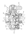
- FIG. 1 It is a perspective view which shows the state which connected the switching cock for water purifiers of this invention to the faucet of a faucet, and connected the water purifier to this switching cock for water purifiers. It is a perspective view which shows the state which is going to connect the connection hose from a water purifier to the back side of the switching cock for water purifiers. It is an enlarged longitudinal cross-sectional view of the switching cock for water purifiers at the time of normal discharge.
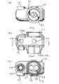
- the cock main body which comprises the switching cock for water purifiers which concerns on this invention is shown, (a) is a top view, (b) is a longitudinal cross-sectional view, (c) is a seat surface view.
- (A) is a plan view
- (b) is a right side view
- (c) is a front view
- (d) is a view from a switching rotator which constitutes the switching cock for the water purifier.
- 3 is a cross-sectional view taken along the line 3-3
- (e) is a cross-sectional view taken along the line 4-4 in (c).
- the pressure control valve which comprises the switching cock for water purifiers which concerns on this invention is shown, (a) is a perspective view of a pressure control valve, (b) is sectional drawing when pressure is not applied to the pressure control valve, (c) ) Is a cross-sectional view when a high pressure is applied to the pressure control valve.
- FIG. 1 shows a state in which the switching faucet 100 for water purifier according to the present invention is attached to the faucet 210 of the faucet 200 and used, and the switching faucet 100 for water purifier is separate from this and is in the sink , Etc. are connected via two connection hoses 310 to a water purifier 300 installed at another place such as For that purpose, as shown in FIG. 2, the raw water supply port 12 and the purified water inflow port 13 are formed so as to protrude from the back side of the cock body 10 constituting the switching faucet 100 for water purifier.
- Connection hoses 310 are respectively connected to the raw water supply port 12 and the purified water inlet 13, and the other ends of the connection hoses 310 are respectively connected to the water supply port and the water purification port of the water purifier 300 as shown in FIG. It is
- the connection of the switching cock 100 for water purifier to the faucet 210 is made by attaching the fixture 60 to the raw water port 11 formed at the upper end of the cock body 10 constituting the switching cock 100 for water purifier. It is attached and made to be able to be performed via this mounting tool 60.
- the fixture 60 corresponding to the shape of the faucet 210 is prepared, and the water purifier switching faucet 100 can be attached to any faucet 210. It has become.
- the axial center of the cylindrical storage space 10a of the cock body 10 of the switching faucet 100 for water purifier is disposed substantially horizontally.
- the switching rotary member 20 described later is housed in the storage space 10a so as to be movable, the switching rotary member 20 is also arranged so that its axis is substantially horizontal.
- the switching cock 100 for water purifier has a cock main body 10 whose external appearance is shown in FIGS. 1 and 2, a switching rotary element 20 housed and supported substantially horizontally in the cock main body 10, and the switching time
- the switching handle 50 integrated with the outer end (the right end as shown in FIG. 3 in the present embodiment) of the moving element 20 is a basic component.
- the cock body 10 is a cylindrical one having a horizontal cylindrical space for housing the switching rotary member 20, and is a raw water port connected to a faucet 210 of water supply etc. 11, the raw water supply port 12 and the purified water inlet 13 respectively connected to the water supply port and the purified water port on the side of the water purifier 300, the purified water outlet 14 located in the vicinity of the purified water inlet 13 and the vicinity of the raw water port 11 And a shower port 16 located around the normal discharge port 15.
- the raw water supply port 12 of the cock body 10 is connected to the water purifier 300 via the connection hose 310 as shown also in FIG. 1, and for example, as shown in FIG. 9 and FIG. It is always in communication with the water port 11. Therefore, there is a possibility that the raw water of abnormal pressure is supplied to the water purifier 300 side through the raw water supply port 12, or the raw water on the water purifier 300 side may reversely flow back into the cock body 10, but In the switching faucet 100 for water purifier of the embodiment, as shown in FIG. 9 or FIG. 10, such a problem is prevented from occurring by providing the metering plug 12a in the raw water supply port 12.
- the flow control fitting 15a is accommodated in the normal discharge port 15 of the cock body 10, and the normal discharge can be performed without splashing water. The same one as the straightening fitting 15a is also provided in the clean water discharge port 14.
- the switching rotator 20 rotatably housed in the cock body 10 is as shown in FIG. 5, and the normal discharge passage 21 for selectively communicating the raw water port 11 and the normal discharge port 15 with each other.
- a shower discharge passage 22 selectively connecting the raw water port 11 and the shower opening 16 and a clean water discharge passage 23 selectively communicating the clean water inlet 13 and the clean water discharge port 14 in the circumferential direction It is.
- this switching rotary member 20 is housed in a fluid tight manner in the cock main body 10 and is rotated about the axial center in the lateral direction, the right side of the shower discharge passage 22 and the normal discharge passage 21
- An annular groove is formed between the water purification discharge passage 23 and the annular ring, that is, the ring-shaped packing 27.
- the annular packing 27 makes the right side of the shower discharge passage 22, the normal discharge passage 21 and the clean water discharge passage 23 In particular, the sealing is performed with light torque in the circumferential direction.
- each of the pulling-up portions 24 to 26 needs to be configured to have a cylindrical shape when viewed from one end side as shown in (b) of FIG. The specific configuration is shown in (a), (c) and (e) of FIG.
- valve seats 31 to 33 are respectively disposed immediately above the clean water discharge port 14, the normal discharge port 15 and the shower port 16 of the cock body 10, and in the present embodiment, the switching rotary element 20 is Since it is partitioned as described above by the two packings 27, normally the valve seat 31 and the shower valve seat 32 are integrally formed, but these and the clean water valve seat 33 are separately formed is there.
- the valve holes 31a 32a and 33a of the respective valve seats 31 to 33 are circular so as to completely receive and close the respective ball valves 41 to 43.
- the water purifier switching cock 100 normally opens the discharge port 15, the shower port 16 and the clean water discharge port 14 vertically downward, and the normal discharge port 15, the shower port 16, and the clean water discharge port
- the valve seats 31, 32 and 33 are respectively provided immediately above 14, and the ball valves 41, 42 and 43 are rotatably accommodated in the respective discharge passages 21, 22 and 23 of the switching rotor 20.
- the valve body 41, 42, 43 is placed by its own weight on each valve seat 31, 32, 33, the valve port of the valve seat is pierced, and each discharge passage 21, 22 of the switching rotor 20 is made.
- the pull-up portions 24, 25 and 26 are formed to selectively pull up the corresponding ball valves 41, 42 and 43 from the respective valve seats 31 to 32.
- Each of the ball valves 41 to 43 in the present embodiment is made of synthetic rubber as a material so that at least the surface becomes soft. The reason is that the ball valves 41 to 43 are mounted on the valve seats 31 to 33 only by their own weight, and at that time, the valve holes 31a, 32a or 33a can be reliably closed. It is to do so. For the same reason, the valve seats 31 to 33 are also made of a relatively soft synthetic resin.
- the selected discharge of the normal discharge, the shower discharge, and the purified water discharge is stored in the normal discharge passage 21 on the switching rotary element 20 side, the shower discharge passage 22 and the clean water discharge passage 23 respectively.
- This is performed by the one-ball valve body 41, the second ball valve body 42, and the third ball valve body 43.
- the water discharge outlet 14 the normal discharge The outlet 15 and the shower port 16 are opened downward, and the clean water valve seat 33, the normal valve seat 31 and the shower valve seat 32 are opened horizontally, and the respective openings (valve ports) are opened.
- the one-ball valve body 41, the second ball valve body 42, and the third ball valve body 43 can be reliably closed.
- first ball valve body 41, the second ball valve body 42, and the third ball valve body 43 do not have to be closed, that is, the clean water discharge port 14, the normal discharge port 15 or the shower port
- first ball valve body 41, the second ball valve body 42 or the third ball valve body 43 from the respective clean water valve seats 33, usually the valve seat 31 or the shower valve seat 32
- the first pull-up portion 24, the second pull-up portion 25, and the third pull-up portion 26 that perform pull-up must be within the normal discharge passage 21, the shower discharge passage 22, and the clean water discharge passage 23 on the switching rotary element 20 side. It is formed in each.
- the pressure control valve 70 is housed in the raw water port 11 formed in the upper part of the cock main body 10 constituting the switching cock 100 for water purifier .
- the pressure control valve 70 is fixed to the cock body 10 by a fitting 60 screwed to the raw water port 11, and the raw water port 11 has a diameter slightly larger than the diameter of the pressure control valve 70 which is not deformed.
- a material having a diameter of about 1.8 cm and a thickness of about 3 mm is integrally formed of synthetic rubber such as silicone rubber or propylene rubber. Then, as shown in (a) to (b) of FIG. 6, the pressure control valve 70 is accommodated so as to be contractible in the direction orthogonal to the flow path in the storage portion 21 and has a wall parallel to the flow path Base portion 71, an annular plate portion 72 integrated on the secondary side of the base portion 71, and an inner end of the annular plate portion 72, the tip 13a is inclined toward the primary side of the flow path An annular inclined portion 73 and a through hole 74 formed on the tip 13 a side of the annular inclined portion 73 are provided.
- the pressure adjusting valve 70 is formed such that the tip 73 a of the annular inclined portion 73 when no force is applied is completely accommodated in the raw water port 11. is there. By doing in this way, when it bend
- the normal discharge passage 21 and the normal discharge port 15 are communicated with each other, and the communication between the shower discharge passage 22 and the shower port 16 and the clean water discharge passage 23 and the clean water discharge port 14 is the second ball valve 42
- the raw water blocked by the third ball valve 43 and supplied to the raw water port 11 side is usually discharged from the discharge port 15 through the discharge passage 21.
- the raw water port 11 normally communicates with the discharge passage 21 and the shower discharge path 22, and as shown in FIGS. 9 to 11, the raw water port 11 is connected to the raw water supply port 12. It also communicates. Therefore, the pressure of the raw water supplied from the faucet 210 of the faucet 200 is always applied to the discharge passage 21 and the shower discharge passage 22 and also to the raw water supply port 12 side. However, since the metering plug 12a is provided in the raw water supply port 12 and the clean water discharge port 14 is not opened, the raw water from the faucet 210 not only flows into the water purifier 300 but also Water does not flow back from the water purifier 300 to the water purifier switching cock 100 side.
- the clean water discharge port 14 of the switching cock 100 for the water purifier opens downward, and the valve port 33 a of the clean water valve seat 33 is the third ball valve on the clean water valve seat 33.
- the third ball in the clean water discharge passage 23 is drilled by the body 43, and a certain amount of water pressure from the faucet 210 is applied to the third ball valve body 43 through the metering plug 12a in the raw water supply port 12.
- the valve body 43 is in close contact with the clean water valve seat 33 unless it is forcibly pulled up from the clean water valve seat 33 by the third pulling-up unit 26.
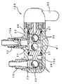
- FIGS. 7 and 10 The state in which shower discharge is performed in the switching cock 100 for water purifier is shown in FIGS. 7 and 10, and in the case of the embodiment, the switching handle 50 is directed downward. Further, at this time, as shown in FIG. 7, only the second ball valve body 42 is pulled up by the second raising portion 25 and pulled away from the shower valve seat 32, and the first ball valve The body 41 is normally placed on the valve seat 31 and the third ball valve 43 is placed on the clean water valve seat 33.
- the raw water port 11 to which the faucet 210 is connected is in communication with the shower port 16 through the shower discharge passage 22, so that raw water is discharged from the shower port 16 in a shower state.
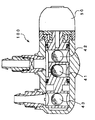
- the state in which the water purification discharge is being performed in the switching cock 100 for water purifier is shown in FIG. 8 and FIG. 11, and the switching handle 50 is pivoted so as to protrude upward as shown in FIG. .
- the first ball valve body 41 and the second ball valve body 42 normally close the valve seat 31 and the shower valve seat 32 by their own weight, and the third ball valve body 43 is formed in the purified water discharge passage 23 It is pulled up from the purified water valve seat 33 by a certain third raising portion 26, and the purified water discharge port 14 is in an open state.
- the raw water of the faucet 210 supplied from the raw water port 11 passes through the metering plug 12 a of the raw water supply port 12 and is supplied into the water purifier 300, and the raw water is collected in the water purifier 300. Purification is performed, and the water is returned to the side of the water purifier switching cock 100 through the connection hose 310. And since the purified water discharge port 14 is open
- the selective opening and closing of the clean water discharge port 14, the normal discharge port 15, and the shower port 16 is performed by the normal valve seat 31, the shower valve seat 32, and the clean water Since the first ball valve body 41, the second ball valve body 42 and the third ball valve body 43 are pulled up on the valve seat 33 and placed by their own weight, for example, the cock body 10 and the switching rotary element If compared with the opening and closing by sliding contact with 20, the seal structure can be simplified, the structure can be simplified, and the durability can be made high.
- the water purification outlet 14 is opened downward, and the water purification valve seat 33 is made horizontal, and the opening and closing of the valve opening 33 a of the water purification valve seat 33 is described above. Since the third ball valve 43 is used, it is possible to block the entry of air when the purified water is not being discharged.
Landscapes
- Engineering & Computer Science (AREA)
- General Engineering & Computer Science (AREA)
- Mechanical Engineering (AREA)
- Health & Medical Sciences (AREA)
- Life Sciences & Earth Sciences (AREA)
- Hydrology & Water Resources (AREA)
- Public Health (AREA)
- Water Supply & Treatment (AREA)
- Multiple-Way Valves (AREA)
- Domestic Plumbing Installations (AREA)
- Water Treatment By Sorption (AREA)
Abstract
L'invention concerne un robinet commutateur qui : est capable d'effectuer trois types de commutation, vers une distribution normale, une distribution de douche et une distribution d'eau purifiée; a une structure simple et est capable d'empêcher l'entrée d'air qui peut devenir une source de microbes contaminants; coupe efficacement l'eau après utilisation; et permet un ajustement facile de la pression. Le corps principal du robinet (10) comprend un orifice d'entrée d'eau brute (11), un orifice de distribution d'eau brute (12), un orifice d'entrée d'eau purifiée (13), un orifice de distribution d'eau purifiée (14), un orifice de distribution normale (15), et un orifice de douche (16). Le système rotatif de commutation (20) comprend, à des positions respectives dans la direction circonférentielle : un passage de distribution normale (21) qui permet sélectivement à l'orifice d'eau brute (11) de communiquer avec l'orifice de distribution normale (15); un passage de distribution de douche (22) qui permet sélectivement à l'orifice d'eau brute (11) de communiquer avec l'orifice de distribution de douche (16); et un passage de distribution d'eau purifiée (23) qui permet sélectivement à l'orifice d'entrée d'eau purifiée (13) de communiquer avec l'orifice de distribution d'eau purifiée (14). Une vanne de réglage de pression (70) est située dans l'orifice d'eau brute du corps principal de robinet (10), la vanne de réglage de pression étant constituée d'une base (71), d'une plaque circulaire (72) intégrée à ladite base (71), d'une pièce circulaire inclinée (73) qui est intégrée au bord intérieur de la plaque circulaire (72) et dont l'extrémité pointue (73a) est inclinée vers le premier côté du canal d'écoulement, et d'un trou traversant (74) formé dans le côté de l'extrémité pointue (73a) de la pièce circulaire inclinée (73).
Applications Claiming Priority (2)
| Application Number | Priority Date | Filing Date | Title |
|---|---|---|---|
| JP2011087071A JP2012219525A (ja) | 2011-04-11 | 2011-04-11 | 浄水器用切換コック |
| JP2011-087071 | 2011-04-11 |
Publications (1)
| Publication Number | Publication Date |
|---|---|
| WO2012140706A1 true WO2012140706A1 (fr) | 2012-10-18 |
Family
ID=46990533
Family Applications (1)
| Application Number | Title | Priority Date | Filing Date |
|---|---|---|---|
| PCT/JP2011/006260 WO2012140706A1 (fr) | 2011-04-11 | 2011-11-09 | Robinet commutateur pour purificateur d'eau |
Country Status (3)
| Country | Link |
|---|---|
| JP (1) | JP2012219525A (fr) |
| CN (1) | CN102734502A (fr) |
| WO (1) | WO2012140706A1 (fr) |
Families Citing this family (4)
| Publication number | Priority date | Publication date | Assignee | Title |
|---|---|---|---|---|
| CN103836251B (zh) * | 2012-11-23 | 2017-03-29 | 杜也兵 | 净水器轴压式换向阀的控制方法及手柄机构操控方法 |
| CN106195343B (zh) * | 2016-08-31 | 2018-05-15 | 福建金源泉科技发展有限公司 | 一种净水器用减压龙头分水器 |
| CN106195416B (zh) * | 2016-09-06 | 2018-04-17 | 东莞市倍益清环保科技有限公司 | 一种控水装置及含有控水装置的一体式水龙头净水器 |
| KR20180062623A (ko) * | 2016-12-01 | 2018-06-11 | 박영석 | 싱크대용분기밸브 |
Citations (3)
| Publication number | Priority date | Publication date | Assignee | Title |
|---|---|---|---|---|
| JPH112343A (ja) * | 1997-06-16 | 1999-01-06 | Hayakawa Valve Seisakusho:Kk | 浄水器用切換コック |
| WO2004027298A1 (fr) * | 2002-09-17 | 2004-04-01 | Hayakawa Valve Production Co., Ltd. | Unite de valve pour robinet selecteur, et robinet selecteur ainsi equipe |
| JP2004183247A (ja) * | 2002-11-29 | 2004-07-02 | Hayakawa Valve Seisakusho:Kk | 流量計付吐水装置、流量計付切替コック、流量計付フレキ吐水管、浄活水器用流量計、アンダーシンク型浄活水器用流量計付水栓及び流量計ユニット |
-
2011
- 2011-04-11 JP JP2011087071A patent/JP2012219525A/ja active Pending
- 2011-07-04 CN CN2011101883357A patent/CN102734502A/zh active Pending
- 2011-11-09 WO PCT/JP2011/006260 patent/WO2012140706A1/fr active Application Filing
Patent Citations (3)
| Publication number | Priority date | Publication date | Assignee | Title |
|---|---|---|---|---|
| JPH112343A (ja) * | 1997-06-16 | 1999-01-06 | Hayakawa Valve Seisakusho:Kk | 浄水器用切換コック |
| WO2004027298A1 (fr) * | 2002-09-17 | 2004-04-01 | Hayakawa Valve Production Co., Ltd. | Unite de valve pour robinet selecteur, et robinet selecteur ainsi equipe |
| JP2004183247A (ja) * | 2002-11-29 | 2004-07-02 | Hayakawa Valve Seisakusho:Kk | 流量計付吐水装置、流量計付切替コック、流量計付フレキ吐水管、浄活水器用流量計、アンダーシンク型浄活水器用流量計付水栓及び流量計ユニット |
Also Published As
| Publication number | Publication date |
|---|---|
| CN102734502A (zh) | 2012-10-17 |
| JP2012219525A (ja) | 2012-11-12 |
Similar Documents
| Publication | Publication Date | Title |
|---|---|---|
| JP4648971B2 (ja) | 浄水器 | |
| US5705067A (en) | Mixing faucet with water purifier | |
| US7610931B2 (en) | Bypass valve with an integral flow sensor for a water treatment system | |
| US6634380B2 (en) | Ceramic disc diverter valve | |
| US11391021B2 (en) | Plumbing component | |
| WO2012140706A1 (fr) | Robinet commutateur pour purificateur d'eau | |
| US11028942B2 (en) | Fluid control valve | |
| CN101239261A (zh) | 可反流冲洗的过滤器 | |
| JP5275938B2 (ja) | 流量調整止水栓 | |
| CA2504328A1 (fr) | Vanne de derivation | |
| MXPA05001286A (es) | Sello de filtro para una valvula de control de fluido. | |
| JP3081892B2 (ja) | 浄水器用切換コック | |
| CN101524602A (zh) | 可反冲洗的过滤器 | |
| KR200391700Y1 (ko) | 정수기용 필터카트리지 연결구조 | |
| EP2186952A2 (fr) | Dispositif de connexion pour un robinet et méthode de connection des parties d'un robinet | |
| JP2011027198A (ja) | 切換コック | |
| KR20140076906A (ko) | 친환경 일체형 연결 아답터 | |
| KR101179375B1 (ko) | 감압밸브 | |
| JPH0860712A (ja) | 分岐管ヘッダー | |
| AU2003213322B2 (en) | Stop/check valve for plumbing use | |
| JP5363040B2 (ja) | 壁内蔵型給水栓及びその取付構造 | |
| JP2005133451A (ja) | 分岐口付水栓 | |
| GB2579960A (en) | A plumbing component | |
| JP2001152494A (ja) | 埋込水栓 | |
| JP2006009301A (ja) | 給水アタッチメント |
Legal Events
| Date | Code | Title | Description |
|---|---|---|---|
| 121 | Ep: the epo has been informed by wipo that ep was designated in this application |
Ref document number: 11863300 Country of ref document: EP Kind code of ref document: A1 |
|
| NENP | Non-entry into the national phase |
Ref country code: DE |
|
| 122 | Ep: pct application non-entry in european phase |
Ref document number: 11863300 Country of ref document: EP Kind code of ref document: A1 |