WO2012137835A1 - コードストッパー - Google Patents
コードストッパー Download PDFInfo
- Publication number
- WO2012137835A1 WO2012137835A1 PCT/JP2012/059237 JP2012059237W WO2012137835A1 WO 2012137835 A1 WO2012137835 A1 WO 2012137835A1 JP 2012059237 W JP2012059237 W JP 2012059237W WO 2012137835 A1 WO2012137835 A1 WO 2012137835A1
- Authority
- WO
- WIPO (PCT)
- Prior art keywords
- cap
- hole
- case
- slit
- opening
- Prior art date
- Legal status (The legal status is an assumption and is not a legal conclusion. Google has not performed a legal analysis and makes no representation as to the accuracy of the status listed.)
- Ceased
Links
Images



Classifications
-
- A—HUMAN NECESSITIES
- A45—HAND OR TRAVELLING ARTICLES
- A45C—PURSES; LUGGAGE; HAND CARRIED BAGS
- A45C13/00—Details; Accessories
- A45C13/42—Devices for identifying luggage; Means for attaching same
-
- F—MECHANICAL ENGINEERING; LIGHTING; HEATING; WEAPONS; BLASTING
- F16—ENGINEERING ELEMENTS AND UNITS; GENERAL MEASURES FOR PRODUCING AND MAINTAINING EFFECTIVE FUNCTIONING OF MACHINES OR INSTALLATIONS; THERMAL INSULATION IN GENERAL
- F16G—BELTS, CABLES, OR ROPES, PREDOMINANTLY USED FOR DRIVING PURPOSES; CHAINS; FITTINGS PREDOMINANTLY USED THEREFOR
- F16G11/00—Means for fastening cables or ropes to one another or to other objects; Caps or sleeves for fixing on cables or ropes
- F16G11/02—Means for fastening cables or ropes to one another or to other objects; Caps or sleeves for fixing on cables or ropes with parts deformable to grip the cable or cables; Fastening means which engage a sleeve or the like fixed on the cable
- F16G11/025—Fastening means which engage a sleeve or the like fixed on the cable, e.g. caps
Definitions
- the present invention relates to a cord stopper that is attached to an end of a string that is passed through a string such as clothing or a storage bag, and in particular, a cylindrical case part that accommodates a knot formed at the end of the string is formed by a cap part. It relates to a closed cord stopper.
- FIGS. 5A and 5B are cross-sectional views showing the internal cross-sectional structure of the cord stopper, and showing the process of attaching the cord stopper to the end of the string.
- a cap part 70 is formed integrally with a cylindrical case part 50 of the cord stopper via a belt-like hinge part 60.
- a base end opening 51 for inserting the string K into the cylinder of the case portion 50 is formed at the lower cylindrical end of the case portion 50, and the case portion 50 has an upper cylindrical end at the upper cylindrical end.
- a circular hole-shaped tip opening 52 for drawing the string K out of the 50 cylinders is formed.
- An inner diameter Ra1 of the distal end opening 52 is larger than an inner diameter Ra2 of the proximal end opening 51, and when the knot portion Ka of the string K pulled out from the distal end opening 52 is pulled back from the proximal end opening 51, the distal end opening It passes through the portion 52 and is locked at the proximal end opening 51.
- the outer peripheral wall 53 of the tip opening 52 is connected to a flexible belt-like hinge portion 60 extending from the thinned portion 54 of the outer peripheral wall 53, and the tip of the hinge portion 60 has a covered truncated cone shape.
- the cap part 70 is connected.
- An outer surface 71S having an outer diameter substantially the same as the outer diameter Rb1 of the outer peripheral wall 53 is formed on the disc-shaped closing portion 71 constituting the cap portion 70.
- the outer surface 71S of the closing portion 71 has a hinge portion.
- the tips of 60 are connected.
- a truncated cone-shaped guide protrusion 72 having an outer diameter smaller than the inner diameter Ra1 of the distal end opening 52 projects from a closed end surface 72S that is a surface facing the distal end opening 52 in the closed section 71.
- the tip of the cord K is moved from the state where the tip opening 52 is opened. It is pulled out to the outside of the case portion 50 through the proximal end opening 51 and the distal end opening 52.
- a knot portion Ka is formed at the distal end of the string K, and then the string K is pulled back from the proximal end opening 51.
- the knot portion Ka of the string K abuts on the stepped portion 55 in the case portion 50 and cannot be pulled out from the proximal end opening portion 51.
- the guide projection 72 opens at the tip opening as shown in FIG.
- the guide projection 72 enters the tip opening 52 while sliding on the portion 52.
- the front end opening 52 of the case portion 50 is closed by the closing portion 71 of the cap portion 70.
- the entire tip opening 52 is covered with the closing portion 71 of the cap portion 70, and the tip opening 52 is thereby closed by the cap portion 70. Therefore, in the state where the tip opening 52 is closed by the cap part 70, only the guide protrusion 72 of the cap part 70 is fitted inside the case part 50, and the closed part 71 of the cap part 70 which is the other part. Protrudes outside the case portion 50. And as a result of the cap part 70 becoming easy to rotate via the hinge part 60, obstruction
- This invention is made
- the present invention closes a cylindrical case portion having a pair of opening portions facing each other and having different hole sizes, and a large opening portion having a large hole among the pair of opening portions.
- a cap portion wherein the case portion and the cap portion are integrally formed via a flexible hinge portion, and the small opening portion having a small hole of the pair of opening portions is the case.
- the slit further includes a slit extending from the cylindrical end surface of the large opening to the small opening, and the end of the slit on the small opening side has a strip shape extending from the end to the large opening.
- the hinge portion is connected,
- the cap portion is coupled to the large opening side of the flange portion, and the entire cap portion is fitted into the hole of the large opening portion and the slit, and the hole of the large opening portion of the cap portion
- the gist of the present invention is that the outer surface closing the surface is flush with the cylindrical end surface of the large opening.
- the entire cap portion is fitted into the hole and slit of the large opening, and the outer surface of the cap portion and the cylinder end surface of the large opening close the hole. Become one. Therefore, it is possible to suppress the portion of the cap portion that is exposed outside the case portion from being caught by an object outside the case portion or being recognized by a tactile sensation such as a finger, and thus the cap fitted into the case portion. It becomes possible to suppress that a part remove
- a base end portion that is a portion connected to the hinge portion is fitted into the slit, and an outer surface of the base end portion that closes the slit is an outer peripheral surface of the case portion It is preferable that they are flush with each other.
- the base end portion of the cap portion is fitted in the slit formed in the outer peripheral wall of the case portion, and the outer surface of the base end portion that closes the slit and the outer peripheral surface of the case portion are flush with each other. . Therefore, it is possible to further suppress the portion of the cap portion exposed to the outside of the case portion from being caught by an object outside the case portion or being recognized by a tactile sense such as a finger.
- the hole of the large opening portion is a hole that is expanded from the slit to the inside of the case portion, and the cap portion has a tapered shape having a width at the tip that is smaller than the width of the slit. Preferably there is.
- the tip of the cap portion has a tapered shape that can be inserted into the slit. For this reason, when the cap portion is fitted into the large opening, it is easy to fit the tip of the case portion into the large opening from the slit. With such a configuration, it is possible to reduce the angle at which the hinge portion is bent as compared with the case where the cap portion is fitted in the direction in which the hole of the large opening extends.
- the case portion has a locking portion formed of a step between the inner surface of the hole of the large opening and the inner surface of the slit, and the distal end portion of the cap portion extends from the proximal end portion of the cap portion.
- the cap portion is widened in the direction of the step, and the cap portion has a locked portion formed by a step between a tip end portion of the cap portion and a base end portion of the cap portion, and the cap portion is a hole of the large opening portion. It is preferable that the locking portion and the locked portion are engaged with each other by being fitted in.
- the cap portion is fitted into the hole of the large opening, so that the locking portion of the case portion and the locked portion of the cap portion are engaged. Therefore, it is possible to further suppress the cap portion from being detached from the case portion in a state where the cap portion is fitted in the hole of the large opening portion.
- the present invention includes a fitting concave portion inside the case portion, a fitting convex portion at a distal end portion of the cap portion, and the cap portion being fitted into a hole of the large opening portion. It is preferable that the mating concave portion and the fitting convex portion are fitted.
- the thickness of the hinge portion is constant. According to this preferable aspect, when the hinge part is bent, a part of the hinge part can be prevented from being greatly bent locally. Therefore, it is possible to increase the mechanical durability of the hinge portion.
- the case portion has an internal space that is expanded from the hole of the small opening portion to the inside of the case portion and communicates with the hole of the large opening portion.
- a step between the internal space of the case portion and the hole of the small opening is formed inside the case portion.
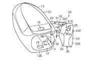
- FIG. 5 is a view similarly showing a perspective structure of the cord stopper, and is a perspective view of the cord stopper before the cap portion is fitted into the case portion, as viewed from the distal end side of the cord stopper.
- FIG. 2 is a view similarly showing the internal structure of the cord stopper, taken along the line AA in FIG. 1.
- FIG. 1 It is a figure which similarly shows the internal structure of a cord stopper, Comprising: (a) The figure which shows the state before a cap part is inserted by a case part, (b) The figure which shows the state by which a part of cap part was inserted by the case part (C) The figure which shows the state by which the whole cap part was engage
- a cap portion 30 is formed integrally with a case portion 10 having an elliptical cylinder shape via a hinge portion 20.
- a circular hole-shaped base end opening 11 as a small opening for inserting a cord into the cylinder of the case 10 is formed at one end of the case 10.
- a rectangular hole-shaped distal end opening portion 12 as a large opening portion for drawing a cord from the inside of the case portion 10 faces the base end opening portion 11. Is formed.
- the distal end opening portion 12 is used when the distal end of the cord inserted from the proximal end opening portion 11 is pulled out from the case portion 10.
- the size of the distal end opening 12 is larger than that of the proximal end opening 11 so that the drawn cord knot can be inserted therethrough.
- a guide slit 13 extending from the cylindrical end surface of the front end opening 12 toward the base end opening 11 is orthogonal to the outer surface of the cap connection wall 10S in the cap connection wall 10S which is the left wall of the peripheral wall of the case portion 10. It penetrates in the horizontal direction, which is the direction to do.
- the slit length L1 that is the length of the guide slit 13 is at least half the case length L2 that is the length of the case portion 10.
- the slit width HB1 that is the width of the guide slit 13 is constant over the entire extending direction of the guide slit 13.
- a strip-like hinge portion 20 extending in the extending direction is connected to the slit base end 13N on the base end opening 11 side of the guide slit 13.
- the wall thickness W which is the width in the lateral direction of the hinge portion 20, is constant throughout the extending direction of the hinge portion 20.
- the hinge width which is the width in the vertical direction of the hinge portion 20, is smaller than the slit width HB1 and is constant throughout the extending direction of the hinge portion 20.
- the overall shape and size of the hinge portion 20 is such that the hinge portion 20 can be accommodated in the guide slit 13.
- a belt-like connecting curved portion 31 that is a base end portion of the cap portion 30 is connected to the tip of the hinge portion 20.
- the connecting curved portion 31 has an outer surface continuous with the outer surface of the hinge portion 20, and an angle between the proximal end side of the connecting bent portion 31 and the distal end side of the connecting bent portion 31 is about 90 °. Further, it is gently bent from the tip of the hinge portion 20.
- the thickness of the connecting curved portion 31 in the horizontal direction is the same as the thickness W of the hinge portion 20 in the horizontal direction, and the connecting width HC1 which is the width in the vertical direction of the connecting curved portion 31 is the slit described above. It is substantially the same as the width HB1.
- a connecting portion contour 31E that is an outer edge in the longitudinal direction of the connecting curved portion 31 is formed in a shape that follows the slit contour 13E that is the inner edge of the guide slit 13.
- the overall shape and size of the connecting curved portion 31 are such that the entire connecting curved portion 31 can be fitted into the guide slit 13.
- the connecting curved portion 31 is fitted into the guide slit 13 so that the slit contour 13E and the connecting portion contour 31E described above coincide with each other.
- the outer peripheral surface of the part 10 is flush.
- a triangular plate-shaped connecting protrusion 32 is provided on the inner surface of the connecting bent portion 31 so as to extend inside the connecting bent portion 31.
- a rectangular parallelepiped blocking portion 33 constituting the cap portion 30 is connected to the distal end of the connecting curved portion 31 and the distal end of the connecting protrusion 32.
- the cap width HC2 that is the width in the vertical direction of the closing portion 33 is larger than the above-described connection width HC1 and is substantially the same as the opening width HB2 that is the width of the tip opening portion 12.
- the entire shape and size of the blocking portion 33 are such that the entire blocking portion 33 can be fitted into the hole of the tip opening portion 12.
- the closing portion 33 that is the distal end portion of the cap portion 30 is widened in the vertical direction from the connecting curved portion 31 that is the base end portion of the cap portion 30 and the connecting protrusion 32. Further, on the proximal end side of the closing portion 33, a locked surface 33 a is formed as a planar locked portion extending in the vertical direction from the distal end of the connecting curved portion 31 and the leading end of the connecting protrusion 32. . Thereby, between the to-be-latched surface 33a of the obstruction
- the closed portion contour 33 ⁇ / b> E that is the outer edge of the outer surface 33 ⁇ / b> S of the closed portion 33 is formed to follow the tip opening contour 12 ⁇ / b> E that is the inner edge of the tip opening portion 12.
- the tip opening contour 12 ⁇ / b> E and the blocking portion contour 33 ⁇ / b> E described above coincide with each other.
- the outer surface 33 ⁇ / b> S that closes the hole and the cylindrical end surface of the tip opening 12 are flush with each other.
- a rectangular pyramid-shaped insertion portion 34 that is tapered toward the inside of the case portion 10 at the tip of the closing portion 33 is formed.
- the insertion width HA which is the width in the longitudinal direction at the tip of the insertion portion 34, is smaller than the slit width HB1 described above. According to such a configuration, since the tip shape of the cap portion 30 is a tapered shape that can be inserted into the guide slit 13, when the closing portion 33 is fitted into the hole of the tip opening portion 12, It becomes easy for the insertion portion 34 which is the distal end portion to slide from the guide slit 13 and enter the distal end opening portion 12.
- a pair of upper and lower fitting projections 35 having a triangular prism shape project from both side surfaces of the closing portion 33 in the longitudinal direction along the longitudinal direction of the closing portion 33.
- An insertion surface 35 a that is flush with the case portion 10 side of the insertion portion 34 is formed on the surface of the fitting convex portion 35 on the case portion 10 side.
- the hole of the tip opening 12 in the case portion 10 is a hole that is expanded from the guide slit 13 toward the inside of the case portion 10, and the inner surface of the hole of the tip opening 12 and the guide slit are formed inside the case portion 10.
- a locking surface 13 a is formed as a locking portion having a step with the inner surface of 13. The locking surface 13a is engaged with the locked surface 33a described above by fitting the closing portion 33 described above into the hole of the tip opening portion 12.
- a pair of upper and lower fitting recesses 15 extending in the vertical direction pass through both side walls in the vertical direction of the peripheral wall of the case portion 10.
- Each of the pair of upper and lower fitting recesses 15 is fitted with the above-described pair of upper and lower fitting projections 35 by the above-described closing portion 33 being fitted into the hole of the tip opening 12.
- an internal space S that is expanded from the hole of the proximal end opening 11 to the inside of the case part 10 and communicates with the hole of the distal end opening 12 is formed inside the case part 10. Yes.
- a stepped portion 16 formed by the internal space S and the hole of the base end opening portion 11 is formed over the entire circumferential direction of the case portion 10.
- the hinge portion 20 is bent outside the guide slit 13 and the cap portion 30 is outside the guide slit 13. Placed in. From this state, the distal end of the string (not shown) is pulled out of the case portion 10 through the proximal end opening 11 and the distal end opening 12. Next, a knot is formed at the tip of the string, and then the string is pulled back from the proximal end opening 11. Thereby, the knot portion of the string comes into contact with the step portion 16 in the case portion 10 and cannot be pulled out from the proximal end opening portion 11.
- an external force directed from the closing portion 33 of the cap portion 30 toward the case portion 10 is applied to the closing portion 33 through a user's finger or the like.
- the external force acts on the closing portion 33
- the hinge portion 20 via the connecting curved portion 31, and thereby the hinge portion 20 is bent toward the inside of the case portion 10.
- the insertion portion 34 of the cap portion 30 first slides in a substantially lateral direction to guide slits. 13 At this time, as described above, since the insertion portion 34 is formed in a tapered shape, the insertion portion 34 can easily enter the guide slit 13. Subsequently, when the insertion portion 34 further enters the guide slit 13, the width of the guide slit 13 is expanded by the insertion portion 34, and then the closing portion 33 and the connecting curved portion 31 enter the guide slit 13.
- the closing portion 33 is fitted into the hole of the tip opening portion 12, the tip opening contour 12E and the blocking portion contour 33E coincide with each other, and the outer surface 33S that plugs the hole of the tip opening portion 12 in the blocking portion 33. And the end face of the tip opening 12 are flush with each other.
- a portion of the cap portion 30 that is exposed to the outside of the case portion 10 is prevented from being caught by an object outside the case portion 10 or being recognized by a tactile sensation such as a finger. It is possible to suppress the fitted cap portion 30 from being detached from the case portion 10.
- the blocking portion 33 is fitted into the hole of the tip opening 12, and the connecting curved portion 31 is fitted into the guide slit 13. That is, the entire cap portion 30 is fitted into the hole of the tip opening portion 12 and the guide slit 13. And in the hole of the front-end
- the portion of the cap portion 30 that is exposed to the outside of the tip opening portion 12 is prevented from being caught by an object outside the case portion 10 or recognized by a tactile sensation such as a finger. It is possible to suppress the fitted cap portion 30 from being detached from the case portion 10.
- the insertion portion 34 that is the tip of the cap portion 30 has a tapered shape that can be inserted into the guide slit 13. Therefore, when the cap portion 30 is fitted into the tip opening portion 12, it is easy to fit the insertion portion 34 from the guide slit 13 into the tip opening portion 12. As a result, when the cap part 30 is fitted into the tip opening part 12 as compared with the case where the cap part 30 is fitted into the tip opening part 12 along the direction in which the hole of the tip opening part 12 extends, the hinge part 20 is used. It is possible to reduce the angle of bending.
- a step portion 16 is formed between the internal space S of the case portion 10 and the hole of the proximal end opening portion 11.
- the knot portion of the string is easily locked to the step portion 16 between the internal space S of the case portion 10 and the hole of the proximal end opening portion 11. Therefore, it is possible to further suppress the tying portion of the string accommodated in the case portion 10 from coming out of the case portion 10.
- the cap part 30 is fitted in the case part 10 while sliding in the lateral direction, it is possible to reduce stress deformation in the hinge part 20.
- the said embodiment can also be changed and implemented as follows.
- the slit length L1 which is the sum of the length of the hinge part 20 and the length of the connecting curved part 31 may be less than half of the case length L2, and the shape, size and material of the hinge part 20 and the connecting curved part 31 may be used. Accordingly, it is appropriately selected. In short, it is sufficient that the length of the stress does not concentrate inside the hinge part 20 and the connecting curved part 31 in a state where the entire cap part 30 is fitted in the case part 10.
- the cap portion 30 can be fitted into the hole of the tip opening portion 12 along the direction in which the hole of the tip opening portion 12 extends.
- the aspect in which the cap part 30 is fitted into the hole of the distal end opening part 12 may be an aspect in which the cap part 30 is slid in the lateral direction according to the length of the hinge part 20, or the cap part 30 is extended. It may be a mode of sliding in the installation direction.
- the length in the extending direction of the hinge part 20 may be at least twice the wall thickness W of the hinge part 20 from the viewpoint that sufficient flexibility in the hinge part 20 is obtained. Depending on the length of the hinge part 20, it may be smaller than half of the case length L2. Even with such a configuration, it is possible to obtain the effects according to the above (1) to (7).
- a stepped portion 16 is formed which is a step between the hole of the proximal end opening 11 and the internal space S. Inside the case portion 10, the hole and the distal end of the proximal end opening 11 are formed.
- the hole 12 of the opening portion 12 may form a continuous surface, and the step portion 16 described above may be omitted.
- the small opening portion having a small hole in the pair of opening portions of the case portion 10 is configured so that the knot portion of the string housed inside the case portion cannot be pulled out from the inside of the case. . Even with such a configuration, it is possible to obtain the effects (1) to (6).
- the thickness W of the hinge part 20 may gradually increase from the proximal end of the hinge part 20 toward the distal end of the hinge part 20, or from the distal end of the hinge part 20 toward the proximal end of the hinge part 20. It may be configured to gradually increase. If the thickness W of the hinge part 20 is constant or changes gradually, it is possible to prevent the hinge part 20 from being broken by bending of the hinge part 20, and even with such a configuration, It is possible to obtain the effects according to the above (1) to (5).
- the number of the fitting recesses 15 and the number of the fitting projections 35 may be one or three or more, respectively, and even in such a configuration, the above (1) to (5) are applied. It is possible to obtain the effect. Even if the fitting concave portion 15 and the fitting convex portion 35 are omitted, it is possible to obtain the effects according to the above (1) to (4). By omitting the joint convex portion 35, the structure of the case portion 10 and the structure of the cap portion 30 can be simplified.
- the structure of the locking surface 13a and the structure of the locked surface 33a are the structures in which the locking surface 13a and the locked surface 33a are engaged by the cap portion 30 being fitted into the hole of the tip opening portion 12. If it is.
- the locking surface 13 a may be concave with respect to the surface of the guide slit 13, and the locked surface 33 a may be convex with respect to the surface of the connecting curved portion 31.
- the number of these locking parts and the number of the locked parts may be two or more. Even with such a configuration, it is possible to obtain the effects according to the above (1) to (4). Even when the locking portion and the locked portion are omitted, it is possible to obtain the effects according to the above (1) to (3). Is omitted, it is also possible to simplify the structure of the case portion 10 and the structure of the cap portion 30.
- the insertion portion 34 which is the tip of the cap portion 30 may be a flat plate extending in the lateral direction and the extending direction, or may be a tapered shape. In short, any shape may be used as long as the entire cap portion 30 is fitted into the hole of the tip opening portion 12 and the guide slit 13. Even with such a configuration, it is possible to obtain the effects according to the above (1) and (2). In addition, if the portion facing the inside of the case portion 10 is a tapered shape, it is easy to prevent the cap portion 30 from being detached from the hole of the tip opening portion 12 and the guide slit 13. It should be noted that the entire contents of the specification, claims, drawings and abstract of Japanese Patent Application No. 2011-084316 filed on April 6, 2011 are cited here as disclosure of the specification of the present invention. Incorporate.
Landscapes
- Engineering & Computer Science (AREA)
- General Engineering & Computer Science (AREA)
- Mechanical Engineering (AREA)
- Closures For Containers (AREA)
- Buckles (AREA)
- Cartons (AREA)
Abstract
ケース部の外周壁を貫通して先端開口部の孔に連通し、先端開口部の筒端面から基端開口部側へ延びる一つのガイドスリットを備え、ガイドスリットにおける基端開口部側の端部には、該端部から先端開口部側へ延びる帯状のヒンジ部が連結され、キャップ部の全体が、先端開口部の孔、及びガイドスリットに嵌め込まれ、キャップ部のうち先端開口部の孔を塞ぐ外表面が、先端開口部の筒端面と面一である。
Description
本発明は、衣類や収納袋などの紐通しに通された紐の端部に取り付けられるコードストッパーに関し、特に紐の端部に形成された結び部を収容する筒状のケース部がキャップ部によって閉じられるコードストッパーに関するものである。
従来から、例えば特許文献1に記載のように、衣類や収納袋などの紐通しに通された紐の一端に取り付けられる樹脂製のコードストッパーが知られている。図5(a)(b)は、コードストッパーにおける内部の断面構造を示す断面図であって、コードストッパーが紐の端部に取り付けされる過程を示す図である。
図5(a)に示されるように、コードストッパーにおける円筒状のケース部50には、帯状のヒンジ部60を介して、キャップ部70が一体的に成形されている。ケース部50における下方の筒端には、ケース部50の筒内に紐Kが挿入されるための基端開口部51が形成され、また、ケース部50における上方の筒端には、ケース部50の筒内から紐Kが引き出されるための円形孔状の先端開口部52が形成されている。先端開口部52の内径Ra1は、基端開口部51の内径Ra2よりも大きく、先端開口部52から引き出された紐Kの結び部Kaは、基端開口部51から引き戻される際に、先端開口部52を通り、基端開口部51で係止される。
先端開口部52の外周壁53には、該外周壁53の欠肉部54から延びる可撓性を有した帯状のヒンジ部60が連結され、該ヒンジ部60の先端には、有蓋円錐台状のキャップ部70が連結されている。キャップ部70を構成する円盤状の閉塞部71には、上記外周壁53の外径Rb1と略同じ外径からなる外表面71Sが形成され、該閉塞部71の外表面71Sには、ヒンジ部60の先端が連結されている。また、閉塞部71において先端開口部52と向かい合う面である閉塞端面72Sには、先端開口部52の内径Ra1よりも小さい外径を有する円錐台形状のガイド突部72が突設されている。
このような構成によれば、紐Kの先端にコードストッパーが取り付けられる際に、まず、図5(a)に示されるように、先端開口部52が開けられた状態から、紐Kの先端が基端開口部51と先端開口部52とを通じてケース部50の外側へ引き出される。次いで、紐Kの先端に結び部Kaが形成され、その後、紐Kが基端開口部51から引き戻される。これによって、紐Kの結び部Kaが、ケース部50内の段差部55に当接して基端開口部51から引き出し不能になる。続いて、閉塞端面72Sが先端開口部52の筒端面に当接するまで、ヒンジ部60を介してキャップ部70が回転すると、図5(b)に示されるように、ガイド突部72が先端開口部52に摺接しながら、ガイド突部72が先端開口部52内に入り込む。これによって、ケース部50の先端開口部52は、キャップ部70の閉塞部71によって閉ざされる。
ところで、上述したコードストッパーでは、先端開口部52の全体がキャップ部70の閉塞部71に覆われ、これにより、先端開口部52がキャップ部70で閉ざされている。それゆえに、先端開口部52がキャップ部70で閉ざされた状態では、キャップ部70のガイド突部72のみがケース部50の内側に嵌め込まれ、それ以外の部分であるキャップ部70の閉塞部71がケース部50の外側に突出することになる。そして、ヒンジ部60を介してキャップ部70が回転しやすくなる結果、キャップ部70によるケース部50の閉塞が容易に解除されることとなる。
本発明は、こうした実情に鑑みてなされたものであり、その目的は、ケース部からキャップ部が外れることを抑えることの可能なコードストッパーを提供することにある。
本発明は、こうした実情に鑑みてなされたものであり、その目的は、ケース部からキャップ部が外れることを抑えることの可能なコードストッパーを提供することにある。
こうした目的を達成するため、本発明は、互いに向い合う一対の開口部で孔の大きさが互いに異なる筒状のケース部と、前記一対の開口部のうち大きい孔を有した大開口部を閉じるキャップ部とを備え、前記ケース部と前記キャップ部とが、可撓性のヒンジ部を介して一体的に形成され、前記一対の開口部のうち小さい孔を有した小開口部が、前記ケース部の内部に収容される紐の結び部を前記ケース部の内部から引き出し不能にする樹脂製のコードストッパーであって、前記ケース部の外周壁を貫通して前記大開口部の孔に連通し、前記大開口部の筒端面から前記小開口部側へ延びる一つのスリットをさらに備え、前記スリットにおける前記小開口部側の端部には、該端部から前記大開口部側へ延びる帯状の前記ヒンジ部が連結され、該ヒンジ部における前記大開口部側には、前記キャップ部が連結され、前記キャップ部の全体が、前記大開口部の孔、及び前記スリットに嵌め込まれ、前記キャップ部のうち前記大開口部の孔を塞ぐ外表面は、前記大開口部の筒端面と面一であることを要旨とする。
本発明によれば、大開口部の孔とスリットとにキャップ部の全体が嵌め込まれ、この大開口部の孔では、該孔を塞ぐキャップ部の外表面と大開口部の筒端面とが面一となる。それゆえに、キャップ部のうち、ケース部の外側に露出する部分が、ケース部の外側で物に引っ掛かったり、指などの触覚によって認識されたりすることを抑えること、ひいてはケース部に嵌め込まれたキャップ部がケース部から外れることを抑えることが可能となる。
本発明は、前記キャップ部では、前記ヒンジ部に連結される部分である基端部が、前記スリットに嵌め込まれ、前記基端部のうち前記スリットを塞ぐ外表面は、前記ケース部の外周面と面一であることが好ましい。
この好ましい態様によれば、ケース部の外周壁に形成されたスリット内にキャップ部の基端部が嵌め込まれ、スリットを塞ぐ基端部の外表面とケース部の外周面とが面一になる。それゆえに、キャップ部のうちケース部の外側に露出する部分が、ケース部の外側で物に引っ掛かったり、指などの触覚によって認識されたりすることを、より抑えることが可能になる。
本発明は、前記大開口部の孔が、前記スリットから前記ケース部の内側へ拡開された孔であり、前記キャップ部は、前記スリットの幅よりも小さい幅を先端に有した先細り形状であることが好ましい。
この好ましい態様によれば、キャップ部の先端は、スリットに挿入可能な先細り形状である。そのため、キャップ部を大開口部に嵌め込む際には、ケース部の先端をスリットから大開口部へ嵌め込むことが容易なものになる。このような構成であれば、大開口部の孔の延びる方向にキャップ部が嵌め込まれる場合と比較して、ヒンジ部の折り曲げられる角度を小さくすることが可能である。
本発明は、前記ケース部が、前記大開口部の孔における内面と前記スリットの内面との段差からなる係止部を有し、前記キャップ部の先端部が、前記キャップ部の基端部から前記段差の方向に拡幅され、前記キャップ部が、前記キャップ部の先端部と前記キャップ部の基端部との段差からなる被係止部を有し、前記キャップ部が前記大開口部の孔に嵌め込まれることで、前記係止部と前記被係止部とは係合することが好ましい。
この好ましい態様によれば、キャップ部が大開口部の孔に嵌め込まれることで、ケース部の係止部とキャップ部の被係止部とが係合する。そのため、キャップ部が大開口部の孔に嵌め込まれた状態にて、キャップ部がケース部から外れることを、より抑えることが可能となる。
本発明は、前記ケース部の内部に嵌合凹部を有し、前記キャップ部の先端部に嵌合凸部を有し、前記キャップ部が前記大開口部の孔に嵌め込まれることで、前記嵌合凹部と前記嵌合凸部とは嵌合することが好ましい。
この好ましい態様によれば、ケース部に嵌め込まれたキャップ部が該ケース部から外れることを、より抑えることが可能となる。
本発明は、前記ヒンジ部の厚さが一定であることが好ましい。
この好ましい態様によれば、ヒンジ部が折り曲げられる際に、ヒンジ部における一部が局所的に大きく折り曲げられることが抑えられる。それゆえに、ヒンジ部の機械的な耐久性を高めることが可能である。
この好ましい態様によれば、ヒンジ部が折り曲げられる際に、ヒンジ部における一部が局所的に大きく折り曲げられることが抑えられる。それゆえに、ヒンジ部の機械的な耐久性を高めることが可能である。
本発明は、前記ケース部は、前記小開口部の孔から前記ケース部の内側へ拡開されて前記大開口部の孔に連通する内部空間を有することが好ましい。
この好ましい態様によれば、ケース部の内部に、該ケース部が有する内部空間と小開口部の孔との段差が形成される。これにより、ケース部が有する内部空間と小開口部の孔との段差に紐の結び部が係止されやすくなる。それゆえに、ケース部内に収容された紐の結び部がケース部内から抜け出ることを、より抑えることが可能である。
この好ましい態様によれば、ケース部の内部に、該ケース部が有する内部空間と小開口部の孔との段差が形成される。これにより、ケース部が有する内部空間と小開口部の孔との段差に紐の結び部が係止されやすくなる。それゆえに、ケース部内に収容された紐の結び部がケース部内から抜け出ることを、より抑えることが可能である。
以下、本発明のコードストッパーを具体化した一実施形態について、図1を参照して説明する。図1に示されるように、樹脂製のコードストッパーでは、楕円筒状をなすケース部10にヒンジ部20を介してキャップ部30が一体的に成形されている。
ケース部10における一方の筒端には、ケース部10の筒内にコードを挿入するための小開口部としての円形孔状の基端開口部11が形成されている。一方、ケース部10における他方の筒端には、ケース部10の筒内からコードを引き出すための大開口部としての矩形孔状の先端開口部12が、基端開口部11と互いに向い合うように形成されている。先端開口部12は、基端開口部11から挿入されるコードの先端をケース部10から引き出す際に用いられる。こうした先端開口部12のサイズは、引き出されたコードの結び部が挿通するように、基端開口部11よりも大きく形成されている。
ケース部10の周壁のうち左側の壁であるキャップ連結壁10Sには、先端開口部12の筒端面から基端開口部11に向けて延びるガイドスリット13が、キャップ連結壁10Sの外表面と直交する方向である横方向に貫通している。ガイドスリット13の延びる方向である延設方向において、ガイドスリット13の長さであるスリット長L1は、ケース部10の長さであるケース長L2の半分以上である。また、延設方向及び横方向と直交する方向である縦方向において、ガイドスリット13の幅であるスリット幅HB1は、ガイドスリット13の延設方向の全体にわたり一定である。
ガイドスリット13における基端開口部11側のスリット基端13Nには、延設方向に延びる帯状のヒンジ部20が連結されている。ヒンジ部20の横方向における幅である肉厚Wは、ヒンジ部20における延設方向の全体にわたり一定である。一方、ヒンジ部20の縦方向における幅であるヒンジ幅は、スリット幅HB1よりも小さく、且つヒンジ部20の延設方向の全体にわたり一定である。そして、ヒンジ部20の全体の形状、及び大きさは、該ヒンジ部20がガイドスリット13に収容されることの可能なものである。
ヒンジ部20の先端には、キャップ部30の基端部である帯状の連結曲部31が連結されている。連結曲部31は、ヒンジ部20の外表面と連続する外表面を有するとともに、該連結曲部31における基端側と連結曲部31における先端側とで挟まれる角度が約90°となるように、ヒンジ部20の先端から緩やかに折れ曲がっている。この連結曲部31の横方向における肉厚は、同じくヒンジ部20における横方向の肉厚Wと同じであって、この連結曲部31の縦方向における幅である連結幅HC1は、上述したスリット幅HB1と略同じである。さらに、連結曲部31の縦方向における外縁である連結部輪郭31Eは、ガイドスリット13の内縁であるスリット輪郭13Eに倣うかたちに形成されている。すなわち、連結曲部31の全体の形状、及び大きさは、ガイドスリット13に該連結曲部31の全体が嵌め込まれることの可能なものである。そして、連結曲部31がガイドスリット13に嵌め込まれることで、上述したスリット輪郭13Eと連結部輪郭31Eとが互いに一致し、これにより、連結曲部31のうちガイドスリット13を塞ぐ外表面とケース部10の外周面とが面一となる。
連結曲部31の内表面には、連結曲部31の内側に広がる三角板状の連結突片32が突設されている。こうした連結突片32が形成されることによって、連結曲部31の曲げ剛性が機械的に補強され、延設方向や横方向への外力に対し、連結曲部31の曲げ剛性がヒンジ部20の曲げ剛性よりも大きくなる。
連結曲部31の先端、及び連結突片32の先端には、キャップ部30を構成する直方体形状の閉塞部33が連結されている。閉塞部33の縦方向における幅であるキャップ幅HC2は、上述した連結幅HC1よりも大きく、且つ先端開口部12の幅である開口幅HB2と略同じである。そして、閉塞部33の全体の形状、及び大きさは、先端開口部12の孔に該閉塞部33の全体が嵌め込まれることの可能なものである。
キャップ部30の先端部である閉塞部33は、キャップ部30の基端部である連結曲部31、及び連結突片32から縦方向へ拡幅されている。そして、閉塞部33の基端側には、連結曲部31の先端、及び連結突片32の先端から縦方向に広がる平面状の被係止部としての被係止面33aが形成されている。これにより、閉塞部33の被係止面33aと連結曲部31の内表面との間には、連結突片32、及び連結曲部31と閉塞部33との段差からなる肉抜き30Cが形成されている。
図2に示されるように、閉塞部33の外表面33Sの外縁である閉塞部輪郭33Eは、先端開口部12の内縁である先端開口輪郭12Eに倣うかたちに形成されている。このような構成によれば、閉塞部33が先端開口部12の孔に嵌め込まれることで、上述した先端開口輪郭12Eと閉塞部輪郭33Eとが互いに一致し、閉塞部33のうち先端開口部12の孔を塞ぐ外表面33Sと先端開口部12における筒端面とが面一となる。
閉塞部33におけるケース部10側には、閉塞部33の先端であって、ケース部10の内側に向けて先細りした四角錐台状の挿入部34が形成されている。挿入部34の先端における縦方向の幅である挿入幅HAは、上述したスリット幅HB1よりも小さい。このような構成によれば、キャップ部30の先端形状が、ガイドスリット13に挿入可能な先細り形状であるため、閉塞部33が先端開口部12の孔に嵌め込まれる際には、閉塞部33の先端部である挿入部34がガイドスリット13からスライドして先端開口部12へ入り込むことが容易なものとなる。
閉塞部33における縦方向の両側面には、該閉塞部33の長手方向に沿って、三角柱状をなす上下一対の嵌合凸部35が突設されている。嵌合凸部35におけるケース部10側の面には、挿入部34におけるケース部10側と面一となる挿入面35aが形成されている。そして、上述した挿入部34が先端開口部12の孔に嵌め込まれると、このような形状からなる嵌合凸部35では、挿入部34に摺接する先端開口輪郭12Eが挿入部34から嵌合凸部35にかけて連続的に摺動することになる。これにより、挿入部34の全体が先端開口部12の内部に進入することが容易なものとなる。
ケース部10における先端開口部12の孔は、ガイドスリット13からケース部10の内側に向けて拡開された孔であり、ケース部10の内部に、先端開口部12の孔における内面とガイドスリット13の内面との段差からなる係止部としての係止面13aを形成している。この係止面13aは、上述した閉塞部33が先端開口部12の孔に嵌め込まれることで、上述した被係止面33aと係合する。
また、ケース部10の周壁のうち縦方向の両側壁には、縦方向に延びる上下一対の嵌合凹部15が貫通している。これら上下一対の嵌合凹部15の各々は、上述した閉塞部33が先端開口部12の孔に嵌め込まれることで、上述した上下一対の嵌合凸部35と嵌合する。
図3に示されるように、ケース部10の内部には、基端開口部11の孔からケース部10の内側へ拡開されて先端開口部12の孔に連通する内部空間Sが形成されている。そして、こうした形状からなる内部空間Sが形成されることで、該内部空間Sと基端開口部11の孔とによる段差部16が、ケース部10の周方向の全体にわたり形成されている。このような構成によれば、ケース部10が有する内部空間Sと基端開口部11の孔との段差に紐の結び部が係止されやすくなる。それゆえに、ケース部10内に収容された紐の結び部がケース部10内から抜け出ることを、より抑えることが可能である。
次に、上述した構成からなるコードストッパーの作用について以下に説明する。
次に、上述した構成からなるコードストッパーの作用について以下に説明する。
コードストッパーが紐の端部に取り付けられる場合には、まず、図4(a)に示されるように、ヒンジ部20がガイドスリット13の外側に折り曲げられて、キャップ部30がガイドスリット13の外側に配置される。この状態から、図示されない紐の先端が、基端開口部11と先端開口部12とを通じてケース部10の外側へ引き出される。次いで、紐の先端に結び部が形成され、その後、紐が基端開口部11から引き戻される。これによって、紐の結び部がケース部10内の段差部16に当接して基端開口部11から引き出し不能になる。
次いで、キャップ部30の閉塞部33からケース部10に向く外力が、利用者の指などを通して、閉塞部33に対して加えられる。そして、このような外力が閉塞部33に作用すると、該外力が連結曲部31を介してヒンジ部20に作用し、これにより、ケース部10の内側に向けてヒンジ部20が折れ曲る。
この際、図4(b)に示されるように、ケース部10の内側に向けてヒンジ部20が折れ曲がることによって、まず、キャップ部30の挿入部34が、略横方向にスライドしてガイドスリット13に入り込む。このとき、上述したように、挿入部34が先細り形状に形成されることから、挿入部34がガイドスリット13へ入り込むことが容易なものとなる。続いて、挿入部34がガイドスリット13にさらに進入すると、ガイドスリット13の幅が挿入部34によって押し広げられ、その後、閉塞部33と連結曲部31とが、ガイドスリット13に入り込む。
そして、閉塞部33と連結曲部31との接続部位である被係止面33aがガイドスリット13を通過して係止面13aに到達すると、図4(c)に示されるように、連結曲部31がガイドスリット13に嵌め込まれる。これにより、スリット輪郭13Eと連結部輪郭31Eとが互いに一致し、そして、連結曲部31のうちガイドスリット13を塞ぐ外表面とケース部10の外周面とが面一となる。その結果、ケース部10の外周面と連結曲部31の外表面との間にケース部10の外側から異物が入り込む場合には、こうした異物の入り込む方向と連結曲部31の嵌め込まれる方向とが等しくなる。それゆえに、ケース部10の外周面と連結曲部31の外表面との間に異物が入り込むことでキャップ部30が外れることを抑えることが可能となる。
また、閉塞部33が先端開口部12の孔に嵌め込まれて、先端開口輪郭12Eと閉塞部輪郭33Eとが互いに一致し、そして、閉塞部33のうち先端開口部12の孔を塞ぐ外表面33Sと先端開口部12における端面とが面一となる。その結果、閉塞部33の外表面33Sと先端開口部12の筒端面との間に異物が入り込むことでキャップ部30が外れることを抑えることが可能となる。その結果、キャップ部30のうち、ケース部10の外側に露出する部分が、ケース部10の外側で物に引っ掛かったり、指などの触覚によって認識されたりすることを抑えること、ひいてはケース部10に嵌め込まれたキャップ部30がケース部10から外れることを抑えることが可能となる。
なお、この際、被係止面33aが係止面13aに到達すると、被係止面33aと係止面13aとが係合して、被係止面33aがケース部10の外側へ移動することが係止される。また、上下一対の嵌合凹部15の各々に上下一対の嵌合凸部35が嵌合する。このような構成によれば、キャップ部30が先端開口部12の孔に嵌め込まれることで、ケース部10の係止面13aとキャップ部30の被係止面33aとが係合し、且つケース部10の嵌合凹部15とキャップ部30の嵌合凸部35とが嵌合する。そのため、ケース部10に嵌め込まれたキャップ部30が該ケース部10から外れることを、より抑えることが可能となる。
以上、本実施形態によれば以下に列記するような効果が得られるようになる。
以上、本実施形態によれば以下に列記するような効果が得られるようになる。
(1)先端開口部12の孔に閉塞部33が嵌め込まれ、ガイドスリット13に連結曲部31が嵌め込まれる。すなわち、先端開口部12の孔とガイドスリット13とにキャップ部30の全体が嵌め込まれる。そして、先端開口部12の孔では、閉塞部33のうち該孔を塞ぐ外表面33Sと先端開口部12の筒端面とが面一となる。
それゆえに、キャップ部30のうち先端開口部12の外側に露出する部分が、ケース部10の外側で物に引っ掛かったり、指などの触覚によって認識されたりすることを抑えること、ひいてはケース部10に嵌め込まれたキャップ部30がケース部10から外れることを抑えることが可能となる。
(2)また、連結曲部31のうちガイドスリット13を塞ぐ外表面とケース部10の外周面とが面一になる。それゆえに、キャップ部30のうちガイドスリット13の外側に露出する部分が、ケース部10の外側で物に引っ掛かったり、指などの触覚によって認識されたりすることを、より抑えることが可能になる。
(3)キャップ部30の先端である挿入部34が、ガイドスリット13に挿入可能な先細り形状である。そのため、キャップ部30を先端開口部12に嵌め込む際には、挿入部34をガイドスリット13から先端開口部12へ嵌め込むことが容易なものになる。ひいては、先端開口部12の孔が延びる方向に沿ってキャップ部30が該先端開口部12に嵌め込まれる場合と比較して、キャップ部30が先端開口部12に嵌め込まれる際には、ヒンジ部20の折り曲げられる角度を小さくすることが可能である。
(4)キャップ部30が先端開口部12の孔に嵌め込まれることで、ケース部10の係止面13aとキャップ部30の被係止面33aとが係合する。そのため、キャップ部30がケース部10から外れることを、より抑えることが可能となる。
(5)キャップ部30が先端開口部12の孔に嵌め込まれることで、ケース部10の嵌合凹部15とキャップ部30の嵌合凸部35とが嵌合する。そのため、ケース部10に嵌め込まれたキャップ部30が該ケース部10から外れることを、より抑えることが可能となる。
(6)ヒンジ部20の肉厚Wが一定であることから、ヒンジ部20の一部が局所的に折り曲げられることを抑えることが可能であり、折り曲げに対するヒンジ部20の機械的な耐性を高めることが可能である。
(7)ケース部10の内部には、該ケース部10が有する内部空間Sと基端開口部11の孔との段差部16が形成される。これにより、ケース部10が有する内部空間Sと基端開口部11の孔との段差部16に紐の結び部が係止されやすくなる。それゆえに、ケース部10内に収容された紐の結び部がケース部10内から抜け出ることを、より抑えることが可能である。
(8)キャップ部30が横方向にスライドしながらケース部10に嵌め込まれるため、ヒンジ部20における応力変形を少なくすることが可能である。
なお、上記実施形態は、以下のように変更して実施することもできる。
(8)キャップ部30が横方向にスライドしながらケース部10に嵌め込まれるため、ヒンジ部20における応力変形を少なくすることが可能である。
なお、上記実施形態は、以下のように変更して実施することもできる。
ヒンジ部20の長さと連結曲部31の長さとの合計であるスリット長L1は、ケース長L2の半分未満であってもよく、ヒンジ部20や連結曲部31の形状、大きさ、材料に応じて、適宜選択されるものである。要は、キャップ部30の全体がケース部10に嵌め込まれた状態で、ヒンジ部20や連結曲部31の内部に応力が集中しない長さであればよい。
ヒンジ部20がガイドスリット13からはみ出す程度に十分に長い構成であれば、先端開口部12の孔が延びる方向に沿って、キャップ部30を先端開口部12の孔へ嵌め込むことが可能である。すなわち、キャップ部30を先端開口部12の孔へ嵌め込む態様は、ヒンジ部20の長さに応じて、キャップ部30を横方向にスライドさせる態様であってもよく、あるいはキャップ部30を延設方向にスライドさせる態様であってもよい。
ヒンジ部20における延設方向の長さは、ヒンジ部20における可撓性が十分に得られるという観点から、ヒンジ部20の肉厚Wの2倍以上であればよく、スリット長L1は、こうしたヒンジ部20の長さに応じて、ケース長L2の半分よりも小さくてもよい。このような構成であっても、上記(1)~(7)に準じた効果を得ることは可能である。
ケース部10の内部には、基端開口部11の孔と内部空間Sとの段差からなる段差部16が形成されているが、ケース部10の内部では、基端開口部11の孔と先端開口部12の孔とが連続面を形成して、上述した段差部16が割愛される構成であってもよい。要は、ケース部10が有する一対の開口部のうち小さい孔を有した小開口部が、ケース部の内部に収容される紐の結び部をケースの内部から引き出し不能にする構成であればよい。このような構成であっても、上記(1)~(6)の効果を得ることは可能である。
ヒンジ部20の肉厚Wは、ヒンジ部20の基端からヒンジ部20の先端に向けて徐々に大きくなる構成であってもよく、あるいはヒンジ部20の先端からヒンジ部20の基端に向けて徐々に大きくなる構成であってもよい。ヒンジ部20の肉厚Wが一定、あるいは徐々に変化するものであれば、ヒンジ部20の曲げによってヒンジ部20が破断することを抑えることが可能であって、このような構成であっても、上記(1)~(5)に準じた効果を得ることが可能である。
嵌合凹部15の数量と嵌合凸部35との数量とは、それぞれ1つあるいは3つ以上であってもよく、このような構成であっても、上記(1)~(5)に準じた効果を得ることが可能である。なお、嵌合凹部15と嵌合凸部35とが割愛される構成であっても、上記(1)~(4)に準じた効果を得ることは可能であって、嵌合凹部15と嵌合凸部35とが割愛されることにより、ケース部10の構造やキャップ部30の構造を簡素化することが可能でもある。
係止面13aの構造、及び被係止面33aの構造は、キャップ部30が先端開口部12の孔に嵌め込まれることで、これら係止面13aと被係止面33aとが係合する構造であればよい。例えば、ガイドスリット13の表面に対し係止面13aが凹状であって、連結曲部31の表面に対し被係止面33aが凸状であってもよい。また、これら係止部の数量、及び被係止部の数量も、2以上であってもよい。このような構成であっても、上記(1)~(4)に準じた効果を得ることが可能である。なお、係止部と被係止部とが割愛される構成であっても、上記(1)~(3)に準じた効果を得ることは可能であって、係止部と被係止部とが割愛されることにより、ケース部10の構造やキャップ部30の構造を簡素化することが可能でもある。
キャップ部30の先端である挿入部34は、横方向、及び延設方向に延びる平板状であってもよく、あるいは先太り形状であってもよい。要は、先端開口部12の孔、及びガイドスリット13に、キャップ部30の全体が嵌め込まれる形状であればよい。このような構成であっても、上記(1)及び(2)に準じた効果を得ることは可能である。また、ケース部10の内側に臨む部分が先太り形状であれば、先端開口部12の孔、及びガイドスリット13からキャップ部30が外れることが抑えられやすくもなる。
なお、2011年4月6日に出願された日本特許出願第2011-084316号の明細書、特許請求の範囲、図面及び要約書の全内容をここに引用し、本発明の明細書の開示として、取り入れるものである。
なお、2011年4月6日に出願された日本特許出願第2011-084316号の明細書、特許請求の範囲、図面及び要約書の全内容をここに引用し、本発明の明細書の開示として、取り入れるものである。
Claims (7)
- 互いに向い合う一対の開口部で孔の大きさが互いに異なる筒状のケース部と、
前記一対の開口部のうち大きい孔を有した大開口部を閉じるキャップ部とを備え、
前記ケース部と前記キャップ部とが、可撓性のヒンジ部を介して一体的に形成され、
前記一対の開口部のうち小さい孔を有した小開口部が、前記ケース部の内部に収容される紐の結び部を前記ケース部の内部から引き出し不能にする
樹脂製のコードストッパーであって、
前記ケース部の外周壁を貫通して前記大開口部の孔に連通し、前記大開口部の筒端面から前記小開口部側へ延びる一つのスリットをさらに備え、
前記スリットにおける前記小開口部側の端部には、該端部から前記大開口部側へ延びる帯状の前記ヒンジ部が連結され、該ヒンジ部における前記大開口部側には、前記キャップ部が連結され、
前記キャップ部の全体が、前記大開口部の孔、及び前記スリットに嵌め込まれ、
前記キャップ部のうち前記大開口部の孔を塞ぐ外表面は、前記大開口部の筒端面と面一であることを特徴とするコードストッパー。 - 前記キャップ部では、前記ヒンジ部に連結される部分である基端部が、前記スリットに嵌め込まれ、
前記基端部のうち前記スリットを塞ぐ外表面は、前記ケース部の外周面と面一である
請求項1に記載のコードストッパー。 - 前記大開口部の孔が、前記スリットから前記ケース部の内側へ拡開された孔であり、
前記キャップ部は、前記スリットの幅よりも小さい幅を先端に有した先細り形状である
請求項2に記載のコードストッパー。 - 前記ケース部が、前記大開口部の孔における内面と前記スリットの内面との段差からなる係止部を有し、
前記キャップ部の先端部が、前記キャップ部の基端部から前記段差の方向に拡幅され、
前記キャップ部が、前記キャップ部の先端部と前記キャップ部の基端部との段差からなる被係止部を有し、
前記キャップ部が前記大開口部の孔に嵌め込まれることで、前記係止部と前記被係止部とは係合する
請求項3に記載のコードストッパー。 - 前記ケース部の内部に嵌合凹部を有し、
前記キャップ部の先端部に嵌合凸部を有し、
前記キャップ部が前記大開口部の孔に嵌め込まれることで、前記嵌合凹部と前記嵌合凸部とは嵌合する
請求項1~4のいずれか一項に記載のコードストッパー。 - 前記ヒンジ部の厚さが一定である
請求項1~5のいずれか一項に記載のコードストッパー。 - 前記ケース部は、前記小開口部の孔から前記ケース部の内側へ拡開されて前記大開口部の孔に連通する内部空間を有する
請求項1~6のいずれか一項に記載のコードストッパー。
Priority Applications (1)
| Application Number | Priority Date | Filing Date | Title |
|---|---|---|---|
| CN201280027704.7A CN103607922B (zh) | 2011-04-06 | 2012-04-04 | 绳固定器 |
Applications Claiming Priority (2)
| Application Number | Priority Date | Filing Date | Title |
|---|---|---|---|
| JP2011084316A JP2012217540A (ja) | 2011-04-06 | 2011-04-06 | コードストッパー |
| JP2011-084316 | 2011-04-06 |
Publications (1)
| Publication Number | Publication Date |
|---|---|
| WO2012137835A1 true WO2012137835A1 (ja) | 2012-10-11 |
Family
ID=46969229
Family Applications (1)
| Application Number | Title | Priority Date | Filing Date |
|---|---|---|---|
| PCT/JP2012/059237 Ceased WO2012137835A1 (ja) | 2011-04-06 | 2012-04-04 | コードストッパー |
Country Status (4)
| Country | Link |
|---|---|
| JP (1) | JP2012217540A (ja) |
| CN (1) | CN103607922B (ja) |
| TW (1) | TWI508678B (ja) |
| WO (1) | WO2012137835A1 (ja) |
Families Citing this family (1)
| Publication number | Priority date | Publication date | Assignee | Title |
|---|---|---|---|---|
| EP3162231B1 (en) | 2015-10-29 | 2018-04-18 | Globeride, Inc. | Hood for clothing and hooded garment |
Citations (2)
| Publication number | Priority date | Publication date | Assignee | Title |
|---|---|---|---|---|
| JPH01154813U (ja) * | 1988-04-11 | 1989-10-25 | ||
| JPH1199008A (ja) * | 1997-09-30 | 1999-04-13 | Nifco Inc | 紐類の端部カバー |
Family Cites Families (2)
| Publication number | Priority date | Publication date | Assignee | Title |
|---|---|---|---|---|
| JP3262455B2 (ja) * | 1994-05-27 | 2002-03-04 | 株式会社ニフコ | 紐止め具 |
| JP3958854B2 (ja) * | 1997-12-26 | 2007-08-15 | 株式会社ニフコ | 帯、紐状体の端末カバー |
-
2011
- 2011-04-06 JP JP2011084316A patent/JP2012217540A/ja not_active Withdrawn
-
2012
- 2012-04-04 WO PCT/JP2012/059237 patent/WO2012137835A1/ja not_active Ceased
- 2012-04-04 CN CN201280027704.7A patent/CN103607922B/zh active Active
- 2012-04-05 TW TW101112017A patent/TWI508678B/zh active
Patent Citations (2)
| Publication number | Priority date | Publication date | Assignee | Title |
|---|---|---|---|---|
| JPH01154813U (ja) * | 1988-04-11 | 1989-10-25 | ||
| JPH1199008A (ja) * | 1997-09-30 | 1999-04-13 | Nifco Inc | 紐類の端部カバー |
Also Published As
| Publication number | Publication date |
|---|---|
| CN103607922A (zh) | 2014-02-26 |
| TW201247120A (en) | 2012-12-01 |
| TWI508678B (zh) | 2015-11-21 |
| CN103607922B (zh) | 2016-03-02 |
| JP2012217540A (ja) | 2012-11-12 |
Similar Documents
| Publication | Publication Date | Title |
|---|---|---|
| JP5701593B2 (ja) | 2ピースクリップ | |
| US8196338B2 (en) | Fishing line stop having a channel offset | |
| TWI528912B (zh) | buckle | |
| JP2017512512A5 (ja) | ||
| US20090297250A1 (en) | Pen cap and pen barrel coupling structure | |
| US20130110156A1 (en) | Device for Sheet Insertion | |
| TW201632104A (zh) | 用於提升抗扭強度的拉鍊頭組合結構及其滑動件 | |
| US8813321B2 (en) | Buckle | |
| WO2012137835A1 (ja) | コードストッパー | |
| US10093465B2 (en) | Anti-slip cable tie | |
| US20110283486A1 (en) | Adapter for attachment to an elastic cord for coupling accessories | |
| JP2022506391A5 (ja) | ||
| JP2008261363A (ja) | なす環 | |
| TWI507144B (zh) | Rope head member | |
| JP6355287B1 (ja) | 弾性継ぎ手 | |
| JP5944105B2 (ja) | 紐留め具 | |
| US9689414B2 (en) | Fastening device for installing a fitting in a holed thin wall | |
| KR200400908Y1 (ko) | 미니 스프링클러용 관연결구 | |
| US9512862B2 (en) | Fastener | |
| JP6683948B2 (ja) | サドル | |
| JP2013104537A (ja) | 取付具 | |
| KR200479755Y1 (ko) | 드레인 플러그 | |
| JP6133067B2 (ja) | スプール連結具及びこれを備えたスプール | |
| JP5836022B2 (ja) | バックル | |
| WO2012137839A1 (ja) | クリップ |
Legal Events
| Date | Code | Title | Description |
|---|---|---|---|
| 121 | Ep: the epo has been informed by wipo that ep was designated in this application |
Ref document number: 12767585 Country of ref document: EP Kind code of ref document: A1 |
|
| NENP | Non-entry into the national phase |
Ref country code: DE |
|
| 122 | Ep: pct application non-entry in european phase |
Ref document number: 12767585 Country of ref document: EP Kind code of ref document: A1 |