WO2012137649A1 - ハニカム構造体用の外形検査装置及びハニカム構造体の製造方法 - Google Patents
ハニカム構造体用の外形検査装置及びハニカム構造体の製造方法 Download PDFInfo
- Publication number
- WO2012137649A1 WO2012137649A1 PCT/JP2012/058170 JP2012058170W WO2012137649A1 WO 2012137649 A1 WO2012137649 A1 WO 2012137649A1 JP 2012058170 W JP2012058170 W JP 2012058170W WO 2012137649 A1 WO2012137649 A1 WO 2012137649A1
- Authority
- WO
- WIPO (PCT)
- Prior art keywords
- honeycomb structure
- face
- displacement sensor
- laser beam
- laser light
- Prior art date
- Legal status (The legal status is an assumption and is not a legal conclusion. Google has not performed a legal analysis and makes no representation as to the accuracy of the status listed.)
- Ceased
Links
Images



Classifications
-
- G—PHYSICS
- G01—MEASURING; TESTING
- G01B—MEASURING LENGTH, THICKNESS OR SIMILAR LINEAR DIMENSIONS; MEASURING ANGLES; MEASURING AREAS; MEASURING IRREGULARITIES OF SURFACES OR CONTOURS
- G01B11/00—Measuring arrangements characterised by the use of optical techniques
-
- G—PHYSICS
- G01—MEASURING; TESTING
- G01B—MEASURING LENGTH, THICKNESS OR SIMILAR LINEAR DIMENSIONS; MEASURING ANGLES; MEASURING AREAS; MEASURING IRREGULARITIES OF SURFACES OR CONTOURS
- G01B11/00—Measuring arrangements characterised by the use of optical techniques
- G01B11/24—Measuring arrangements characterised by the use of optical techniques for measuring contours or curvatures
Definitions
- the present invention relates to an apparatus for inspecting the outer shape of a honeycomb structure having a cell structure and a method for manufacturing the honeycomb structure.
- honeycomb filter structures have been widely known for DPF (Diesel particulate filter) and the like.
- This honeycomb filter structure has a structure in which one end side of some through holes of a honeycomb structure having a large number of through holes is sealed with a sealing material, and the other end side of the remaining through holes is sealed with a sealing material.
- a honeycomb filter structure for DPF is generally used in a state of being housed in a rigid case. If the dimensional accuracy of the honeycomb filter structure is low, problems such as cracks in the honeycomb filter structure due to thermal stress or the like are likely to occur. Therefore, high dimensional accuracy is required for the honeycomb structure (before and after firing) in the manufacturing process. In addition, some honeycomb structures have a narrow cell pitch (for example, about 1.1 to 2.8 mm), and high dimensional accuracy is required for the thickness of partition walls that define a large number of through holes.
- Patent Document 1 discloses a process for inspecting the outer shape of a completed honeycomb structure and an apparatus used therefor.
- FIG. 4 of Patent Document 1 shows a dial gauge 151 having a plurality of rods 152 for inspecting the flatness of the end face of the workpiece 200.
- Patent Document 2 discloses a mounting table used for inspecting a honeycomb structure and an inspection method using the same.
- FIG. 10B of Patent Document 2 shows a shape inspection apparatus 420 having a contact type measuring element 422 for measuring the length of the honeycomb structure 130 and the parallelism of the end face of the honeycomb structure 130. Has been.
- an object of the present invention is to provide an external shape inspection apparatus that can sufficiently prevent defects in the partition walls forming the cell structure of the honeycomb structure when measuring the parallelism of the end faces of the honeycomb structure.
- Another object of the present invention is to provide a method for manufacturing a honeycomb structure including a step of inspecting the outer shape of the honeycomb structure using the outer shape inspection apparatus.
- the present invention is an external shape inspection apparatus for a honeycomb structure having a cell structure, and receives a light source that irradiates a laser beam toward one end face of the honeycomb structure and a laser beam reflected by the one end face.
- An apparatus is provided that includes a displacement sensor having a light receiving unit that outputs an electrical signal corresponding to the intensity of the received laser light, and that measures the parallelism of the end face of the honeycomb structure without contacting the honeycomb structure.
- the external shape inspection apparatus is a non-contact type using a laser beam, when measuring the parallelism of the end face of the honeycomb structure, it is sufficient that defects occur in the partition walls forming the cell structure of the honeycomb structure. Can be prevented.
- the spot shape of the laser light emitted from the light source is preferably an ellipse.
- the irradiation target of the laser beam is not a smooth flat surface or curved surface, but is an end surface of the honeycomb structure, and the end surface has openings forming end portions of a large number of through holes. For this reason, when the spot shape of the laser beam is set to be circular, the spot beam may fall into the opening of the honeycomb structure depending on the measurement position, and the intensity of the reflected beam may be insufficient.
- the spot shape an ellipse and irradiating the end face of the honeycomb structure with a laser beam so that the major axis of the ellipse and the position of the partition wall of the cell structure coincide, reflected light with sufficiently high intensity can be obtained. .
- the external shape inspection apparatus may further include a recording unit that manually or automatically acquires and records the electrical signal output from the light receiving unit.
- the said external shape inspection apparatus may further be equipped with the turntable which mounts a honeycomb structure. If the displacement sensor is fixed above the honeycomb structure mounted on the turntable, the distance from the displacement sensor to the upper surface (one end face) of the honeycomb structure is measured, and then the honeycomb structure is put together with the turntable. The measurement can be repeated by rotating a predetermined angle (for example, 90 °). Thereby, the parallelism of the end surface of the honeycomb structure can be efficiently inspected.
- the rotary table can be rotated manually or automatically.
- the external shape inspection apparatus may further include an automatic control unit that automatically controls the rotary table and the displacement sensor and records measurement data automatically.
- the outer shape inspection apparatus When the XYZ rectangular coordinate system is set, the outer shape inspection apparatus has a surface parallel to the XY plane and movable in the X direction and the Y direction, and the other end surface of the honeycomb structure abuts on the surface.
- the apparatus may further include a table on which the honeycomb structure is placed and a camera that is disposed in the vicinity of the displacement sensor and images one end face.
- a first aspect of a method for manufacturing a honeycomb structure according to the present invention is a method for manufacturing a honeycomb structure having a cell structure, (A1) a step of extruding the raw material composition to obtain a honeycomb structure; (B1) A laser beam is emitted from the displacement sensor toward one end face of the honeycomb structure, and the laser light reflected by the end face is received by the displacement sensor to determine the distance between the displacement sensor and the end face. Measuring the body without contact; (C1) changing the position where the laser beam is irradiated on the end face, and repeating the step (B1) to obtain the parallelism of the end face of the honeycomb structure; Is provided.
- a second aspect of the method for manufacturing a honeycomb structure according to the present invention is a method for manufacturing a honeycomb structure having a cell structure, (A2) a step of firing a green honeycomb molded body to obtain a honeycomb structure; (B2) Laser light is emitted from the displacement sensor toward one end face of the honeycomb structure, and the laser light reflected by the end face is received by the displacement sensor, and the distance between the displacement sensor and the end face is determined by the honeycomb structure. Measuring the body without contact; (C2) changing the position where the laser beam is irradiated on the end face, and repeating the step (B2) to obtain the parallelism of the end face of the honeycomb structure; Is provided.
- the parallelism of the end face of the honeycomb structure (before or after firing) is measured in a non-contact manner with a laser beam. It is possible to sufficiently prevent defects in the partition walls.
- the steps (B1) and (C1) in the first aspect are performed on the honeycomb structure before firing (green honeycomb formed body) to obtain the honeycomb structure after firing.
- honeycomb structure in the present invention includes those before and after firing, and the honeycomb structure before firing is sometimes referred to as “green honeycomb molded body” or simply “green molded body”.
- the above-described method for manufacturing a honeycomb structure preferably further includes (D) a step of reusing a honeycomb structure whose parallelism result does not satisfy the standard with a raw material composition.
- the honeycomb structure that does not satisfy the standard can be effectively used without being discarded.
- the honeycomb structure before firing that does not satisfy the parallelism standard is subjected to treatment such as firing, pulverization, and classification as necessary before mixing with the raw material composition.
- the fired honeycomb structure that does not satisfy the parallelism criterion is subjected to a treatment such as pulverization and classification as necessary before mixing with the raw material composition.
- the above-described method for manufacturing a honeycomb structure may further include a step of taking an image of one end face of the honeycomb structure with a camera and determining a location to be irradiated with laser light. By determining the measurement location based on the image of the camera, sufficiently high intensity reflected light can be stably obtained even when measuring an arbitrary location.
- the present invention when the parallelism of the end face of the honeycomb structure is measured, it is possible to sufficiently prevent defects in the partition walls forming the cell structure of the honeycomb structure.
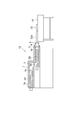
- (A) is a perspective view which shows an example of the honeycomb structure (green honeycomb molded object) before baking
- (b) is the elements on larger scale of the said honeycomb structure.
- It is sectional drawing which shows an example of an extrusion molding apparatus typically.
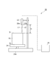
- It is a front view showing typically a suitable embodiment of an outline inspection device concerning the present invention.
- It is a perspective view which shows an example of the measurement location in the upper surface of a honeycomb structure.
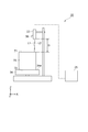
- It is a front view which shows typically other suitable embodiment of the external form inspection apparatus which concerns on this invention.
- a green molded body 70 shown in FIG. 1 is obtained by extruding a raw material composition.
- the green molded body 70 is a cylindrical body in which a large number of through holes 70a are arranged substantially in parallel.
- the through hole 70a is defined by a partition wall 70b, and its cross-sectional shape is a square as shown in FIG.
- the plurality of through holes 70a are arranged in a square arrangement in the green molded body 70, that is, such that the central axis of the through hole 70a is located at the apex of the square.
- the square size of the cross section of the through hole 70a can be set to, for example, 0.8 to 2.5 mm on a side.
- the length of the green molded body 70 in the direction in which the through hole 70a extends is not particularly limited, but may be, for example, 40 to 350 mm. Further, the outer diameter of the green molded body 70 is not particularly limited, but may be, for example, 100 to 320 mm.
- the raw material composition forming the green molded body 70 is not particularly limited.
- an inorganic compound source powder that is a ceramic raw material, an organic binder such as methyl cellulose, and necessary Additives added depending on From the viewpoint of high temperature resistance of the honeycomb structure, suitable ceramic materials include alumina, silica, mullite, cordierite, glass, oxides such as aluminum titanate, silicon carbide, silicon nitride, and the like.
- the aluminum titanate can further contain magnesium and / or silicon.
- the inorganic compound source powder when producing a green molded body of aluminum titanate, includes an aluminum source powder such as ⁇ -alumina powder and a titanium source powder such as anatase type or rutile type titania powder. Furthermore, magnesium source powders such as magnesia powder and magnesia spinel powder and / or silicon source powders such as silicon oxide powder and glass frit can be included.
- organic binder examples include celluloses such as methylcellulose, carboxymethylcellulose, hydroxyalkylmethylcellulose, and sodium carboxymethylcellulose; alcohols such as polyvinyl alcohol; and lignin sulfonate.
- additives examples include pore formers, lubricants and plasticizers, dispersants, and solvents.
- pore-forming agents include carbon materials such as graphite; resins such as polyethylene, polypropylene, and polymethyl methacrylate; plant materials such as starch, nut shells, walnut shells, and corn; ice; and dry ice.
- Lubricants and plasticizers include alcohols such as glycerin; higher fatty acids such as caprylic acid, lauric acid, palmitic acid, arachidic acid, oleic acid and stearic acid; stearic acid metal salts such as Al stearate, polyoxyalkylene alkyl Examples include ether.
- dispersant examples include inorganic acids such as nitric acid, hydrochloric acid and sulfuric acid; organic acids such as oxalic acid, citric acid, acetic acid, malic acid and lactic acid; alcohols such as methanol, ethanol and propanol; ammonium polycarboxylate Surfactant etc. are mentioned.
- the solvent examples include alcohols such as methanol, ethanol, butanol, and propanol; glycols such as propylene glycol, polypropylene glycol, and ethylene glycol; and water.
- the raw material composition is introduced from the inlet 1a of the housing 1 into the flow path 1b.
- the raw material composition is kneaded and transferred downstream.
- a vacuum chamber 3 is provided between the screws 2A and 2B, and the raw material composition can be degassed by reducing the pressure in the vacuum chamber 3.
- a rectifying plate 5 having a large number of through holes is provided, and the flow velocity distribution is made uniform by the raw material composition passing through the opening of the rectifying plate 5. Thereafter, the raw material composition is introduced into the die 8 through the resistance tube 9. The raw material composition is extruded from the die 8, and the compact 70 ⁇ / b> A is collected on the support base 15. The green molded body 70 is obtained by cutting the molded body 70A into a predetermined length.
- the external shape inspection apparatus 20 shown in FIG. 3 measures the parallelism of the end face of the green molded body 70 without contacting the green molded body 70.
- the outline inspection apparatus 20 includes a displacement sensor 22 and a rotary table 24.
- the displacement sensor 22 receives a light source 22a that irradiates the laser beam L1 toward the upper surface (one end surface) 71 of the green molded body 70, the laser beam L2 reflected by the upper surface 71, and the intensity of the received laser beam L2.
- the light receiving unit 22b outputs an electrical signal corresponding to the signal.
- the turntable 24 has a vertical rotation shaft 24a. The green molded body 70 is placed so that the lower surface (the other end surface) 72 is in contact with the rotary table 24.
- the displacement sensor 22 is for measuring the distance D from the light source 22a to the upper surface 71 of the green molded body 70, and includes the light source 22a and the light receiving unit 22b.
- the displacement sensor 22 is fixed above the rotary table 24 and at a position moved in the radial direction from the extended line of the rotary shaft 24a.
- the laser beam L1 can be irradiated substantially vertically downward from such a position.
- the fixed position of the displacement sensor 22 is preferably a position where the laser beam L1 is irradiated about 5 to 15 mm from the outer periphery of the upper surface 71 (see FIG. 4).
- the displacement sensor 22 is preferably configured so that the electrical signal output from the light receiving unit 22b can be sent manually or automatically to a computer (recording means) 25 to store data.
- a computer recording means
- the displacement sensor 22 for example, CD5-W350 (trade name), CD5-W85 (trade name) manufactured by Optics FA Co., Ltd. can be used.
- the computer 25 may be a recording unit and an automatic control unit. In this case, by inputting the operating conditions of the outer shape inspection apparatus 20 to the computer 25, it becomes possible to automatically record measurement data or to automatically control the outer shape inspection apparatus 20.
- the spot shape of the laser beam L1 emitted from the light source 22a is preferably an ellipse (see FIG. 5).
- the spot shape here means the shape of the laser beam (spot S in FIGS. 4 and 5) irradiated on the surface perpendicular to the traveling direction of the laser beam.
- the ratio of the length of the major axis to the length of the minor axis is preferably 25 to 40, and more preferably 28 to 35.
- the length of the major axis of the spot S is preferably about 3 to 10 mm, and the length of the minor axis of the spot S is about 0.2 to 2.5 mm. It is preferable that
- the outer shape inspection apparatus 20 since the inspection can be performed in a non-contact manner using a laser beam, it is possible to sufficiently prevent the partition wall 70b from being defective when measuring the parallelism of the end face of the green molded body 70. Further, since the spot shape of the laser beam L1 is an ellipse, the irradiation target is not a smooth flat surface or curved surface, and even the upper surface 71 of the green molded body 70 composed of a large number of through holes 70a and complicated partition walls 70b is sufficient. High intensity laser light L2 (reflected light) can be obtained, and parallelism inspection can be efficiently performed.
- Green molded body inspection method First, the green molded body 70 is placed on the rotary table 24 so that the central axis thereof coincides with the rotary shaft 24a.
- the laser beam L1 is emitted from the light source 22a toward the upper surface 71.
- the distance D is measured by irradiating the upper surface 71 with the laser beam L1 so that the long axis of the elliptical spot S is along the partition wall 70b of the green molded body 70.
- a sufficiently high intensity laser beam L2 (reflected light) can be obtained.
- the laser beam L2 reflected by the upper surface 71 is received by the light receiving unit 22b, and the distance D is measured without contact with the green molded body 70.
- the green molded body 70 is rotated together with the rotary table 24, and the distance D is measured for the other location.
- the rotary table 24 is moved after the first measurement. It is preferable that the distance D is measured again after being rotated by 90 °. It is preferable to repeat the measurement of the distance D and the rotation of the rotary table 24, and measure the distance D at a total of four locations indicated by black dots in FIG.
- the green molded body 70 is preferably manufactured through the following steps (a1) to (d1).
- A1 The process of obtaining the green molded object 70 by extruding a raw material composition.
- B1 The laser beam L1 is irradiated from the displacement sensor 22 toward the upper surface 71 of the green molded body 70, and the laser beam L2 reflected by the upper surface 71 is received by the displacement sensor 22, and between the displacement sensor 22 and the upper surface 71.
- (C1) A step of changing the position of the upper surface 71 where the laser beam L1 is irradiated and repeating the step (b1) to obtain the parallelism of the end face of the green molded body 70.
- (D1) The green molded body 70 whose parallelism result does not satisfy the standard is subjected to treatment such as firing, pulverization, and classification as necessary, and the obtained powder and the raw material composition in the step (a1) are mixed. And reusing it.
- the green molded body 70 that does not satisfy the standard can be effectively used without being discarded.
- the above-mentioned standard of parallelism is preferably 5 mm or less, and 2 mm or less. More preferably, it is more preferably 1 mm or less.
- the same inspection method as described above can be performed on the fired body of the green molded body 70.
- the fired body (honeycomb structure) of the green molded body 70 is preferably manufactured through the following steps (a2) to (d2).
- A2) A step of firing the green molded body 70 to obtain a honeycomb structure.
- B2) The laser beam L1 is irradiated from the displacement sensor 22 toward the upper surface of the honeycomb structure, and the laser beam L2 reflected by the upper surface of the honeycomb structure is received by the displacement sensor 22, and the displacement sensor 22 and the honeycomb structure A step of measuring the distance between the upper surfaces without contact with the honeycomb structure.
- (C2) A step of changing the position where the laser beam L1 is irradiated on the upper surface of the honeycomb structure, and repeating the step (b2) to obtain the parallelism of the end faces of the honeycomb structure.
- (D2) The honeycomb structure whose parallelism result does not satisfy the standard is subjected to treatment such as pulverization and classification as necessary, and the obtained powder and the raw material composition in the step (a2) are mixed and re-processed. Process to use.
- the honeycomb structure that does not satisfy the standard can be effectively used without being discarded.
- the above-mentioned standard of parallelism is preferably 5 mm or less, and 2 mm or less. Is more preferable, and it is more preferable to set it as 1 mm or less.
- the present invention is not limited to the above-mentioned embodiment.
- the rotary table 24 is adopted and the green molded body 70 (inspection object) is rotated.
- the inspection object does not rotate and the green object 70 is not rotated.
- the displacement sensor 22 may be configured to move so as to draw a circle.
- a table 34 that can move the green molded body 70 in the X direction and the Y direction may be employed instead of the rotary table 24.
- the table 34 provided in the outer shape inspection apparatus 30 has a surface 34a that is parallel to the XY plane and movable in the X direction and the Y direction. On this surface 34a, the green molded body 70 is placed so that the lower surface 72 of the green molded body 70 contacts.
- the table 34 it is possible to irradiate the laser beam L1 to an arbitrary position on the upper surface 71 of the green molded body 70. In this case, as shown in FIG.
- a camera 36 is disposed in the vicinity of the displacement sensor 22 so that the upper surface 71 of the green molded body 70 can be imaged by the camera 36.
- the upper surface 71 of the green molded body 70 is imaged by the camera 36, and the location where the laser light L1 is to be irradiated can be determined.
- the camera 36 a CCD camera or a CMOS camera can be used.
- the cylindrical green molded body 70 is exemplified, but the shape and structure of the molded body are not limited thereto.
- the outer shape of the green molded body 70 may be, for example, a rectangular column such as a quadrangular column or an elliptical column.
- the arrangement of the through holes 70a may not be a square arrangement, and may be, for example, a substantially triangular arrangement, a substantially hexagonal arrangement, or the like.
- the cell shape of the honeycomb structure may not be a square, and may be, for example, a substantially triangular shape, a substantially square shape, a substantially hexagonal shape, a substantially octagonal shape, a substantially circular shape, or a combination thereof.
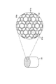
- Examples of the combination of a plurality of shapes include a combination of a regular hexagon and an asymmetric hexagon (see FIG. 7), a combination of a square and an octagon (octosquare), and the like.
- the 7 has a plurality of through holes 81a and 81b having different cross-sectional shapes.
- the plurality of through holes 81 a and 81 b are partitioned by a partition wall 82 extending substantially parallel to the central axis of the green honeycomb molded body 80.
- the through hole 81a has a regular hexagonal cross-sectional shape.
- the through-hole 81b has a flat hexagonal cross-sectional shape and is disposed so as to surround one through-hole 81a.
- the external shape inspection apparatuses 20 and 30 may use the honeycomb structure after the green molded bodies 70 and 80 are subjected to some processing as an inspection target.
- the honeycomb structure after sealing one end of the through holes 70a or the through holes 81a and 81b may be the inspection target.
- the fired honeycomb structure that does not satisfy the parallelism criterion may be improved by polishing the end face or the like, or the honeycomb structure may be pulverized to be a part of the ceramic raw material. May be reused as
- the present invention when the parallelism of the end face of the honeycomb structure is measured, it is possible to sufficiently prevent defects in the partition walls forming the cell structure of the honeycomb structure.
Landscapes
- Physics & Mathematics (AREA)
- General Physics & Mathematics (AREA)
- Length Measuring Devices By Optical Means (AREA)
Abstract
本発明に係る外形検査装置は、セル構造を有するハニカム構造体を検査対象とするものである。外形検査装置は、ハニカム構造体の端面に向けてレーザー光を照射する光源、及び、端面で反射したレーザー光を受光するとともにレーザー光の強度に応じた電気信号を出力する受光部を有する変位センサを備え、ハニカム構造体の端面の平行度を、ハニカム構造体に非接触で測定する。
Description
本発明は、セル構造を有するハニカム構造体の外形を検査するための装置及びハニカム構造体の製造方法に関する。
従来より、ハニカムフィルタ構造体が、DPF(Diesel particulate filter)用等として広く知られている。このハニカムフィルタ構造体は、多数の貫通孔を有するハニカム構造体の一部の貫通孔の一端側を封口材で封じると共に、残りの貫通孔の他端側を封口材で封じた構造を有する。
DPF用のハニカムフィルタ構造体は一般に剛性を有するケースに収容された状態で使用される。ハニカムフィルタ構造体の寸法精度が低いと熱応力等によってハニカムフィルタ構造体に亀裂が入るなどの不具合が生じやすくなる。そのため、製造過程におけるハニカム構造体(焼成前及び焼成後)に対して高い寸法精度が要求される。また、ハニカム構造体は、狭いセルピッチ(例えば1.1~2.8mm程度)を有するものもあり、多数の貫通孔を画成する隔壁の厚さについても高い寸法精度が要求される。
特許文献1には、完成したハニカム構造体の外形を検査する工程及びこれに用いる装置が開示されている。特に、特許文献1の図4にはワーク200の端面の平面度を検査するための複数のロッド152を有するダイヤルゲージ151が図示されている。特許文献2には、ハニカム構造体の検査に用いる載置台及びこれを用いた検査方法が開示されている。特に、特許文献2の図10(b)にはハニカム構造体130の長さ、及び、ハニカム構造体130の端面の平行度を測定するための接触式測定子422を有する形状検査装置420が図示されている。
しかし、特許文献1,2に記載の検査方法のように、ハニカム構造体の端面にロッドや測定子を接触させて検査を行った場合、ハニカム構造体のセル構造をなす隔壁が損傷するなどの欠陥が生じることがあった。なお、かかる欠陥は、焼成前又は焼成後のハニカム構造体のいずれにも起こり得るが、比較的強度が低い焼成後のハニカム構造体の端面の平行度を検査する際に特に生じやすい。
そこで、本発明はハニカム構造体の端面の平行度を測定する際、ハニカム構造体のセル構造をなす隔壁に欠陥が生じることを十分に防止できる外形検査装置を提供すること目的とする。また、本発明は上記外形検査装置を用いてハニカム構造体の外形を検査する工程を備えたハニカム構造体の製造方法を提供することを目的とする。
本発明は、セル構造を有するハニカム構造体用の外形検査装置であって、ハニカム構造体の一方の端面に向けてレーザー光を照射する光源、及び、一方の端面で反射したレーザー光を受光するとともに受光したレーザー光の強度に応じた電気信号を出力する受光部を有する変位センサを備え、ハニカム構造体の端面の平行度を、ハニカム構造体に非接触で測定する装置を提供する。
上記外形検査装置は、レーザー光を利用した非接触式のものであるため、ハニカム構造体の端面の平行度を測定する際、ハニカム構造体のセル構造をなす隔壁に欠陥が生じることを十分に防止できる。
光源から発せられるレーザー光は、スポット形状が楕円であることが好ましい。本発明においては、レーザー光の照射対象は滑らかな平面又は曲面ではなく、ハニカム構造体の端面であり、当該端面は多数の貫通孔の端部をなす開口を有する。このため、レーザー光のスポット形状を円形に設定すると、測定位置によってはスポット光がハニカム構造体の開口に落ち込み、反射光の強度が不十分となる場合がある。スポット形状を楕円とし、当該楕円の長軸とセル構造の隔壁の位置が一致するように、ハニカム構造体の端面にレーザー光を照射することで、十分に高い強度の反射光を得ることができる。
上記外形検査装置は、受光部から出力される電気信号を手動又は自動で取得して記録する記録手段を更に備えるものであってもよい。また、上記外形検査装置は、ハニカム構造体を載置する回転テーブルを更に備えるものであってもよい。回転テーブルに載置されたハニカム構造体よりも上方に変位センサを固定しておけば、変位センサからハニカム構造体の上面(一方の端面)との距離を測定した後、回転テーブルとともにハニカム構造体を所定の角度(例えば、90°)回転させて測定を繰り返すことができる。これにより、ハニカム構造体の端面の平行度を効率的に検査できる。上記回転テーブルは、手動又は自動で回転するものとすることができる。上記外形検査装置は、回転テーブル及び変位センサを自動制御するとともに、測定データを自動で記録する自動制御手段を更に備えるものであってもよい。
上記外形検査装置は、XYZ直交座標系を設定した場合、XY平面に平行であり且つX方向及びY方向に移動可能な面を有し、当該面上にハニカム構造体の他方の端面が当接するようにハニカム構造体が載置されるテーブルと、変位センサの近傍に配置されており、一方の端面を撮像するカメラとを更に備えるものであってもよい。かかる構成を採用することで、平行度を測定するに際し、ハニカム構造体の一方の端面をカメラで撮像し、レーザー光を照射すべき箇所を決定することができる。
本発明に係るハニカム構造体の製造方法の第1の態様は、セル構造を有するハニカム構造体の製造方法であって、
(A1)原料組成物を押出成形してハニカム構造体を得る工程と、
(B1)ハニカム構造体の一方の端面に向けて変位センサからレーザー光を照射するとともに、当該端面で反射したレーザー光を変位センサで受光して変位センサと当該端面の間の距離を、ハニカム構造体に非接触で測定する工程と、
(C1)当該端面におけるレーザー光を照射する位置を変更し、(B1)工程を繰り返してハニカム構造体の端面の平行度を求める工程と、
を備える。
(A1)原料組成物を押出成形してハニカム構造体を得る工程と、
(B1)ハニカム構造体の一方の端面に向けて変位センサからレーザー光を照射するとともに、当該端面で反射したレーザー光を変位センサで受光して変位センサと当該端面の間の距離を、ハニカム構造体に非接触で測定する工程と、
(C1)当該端面におけるレーザー光を照射する位置を変更し、(B1)工程を繰り返してハニカム構造体の端面の平行度を求める工程と、
を備える。
本発明に係るハニカム構造体の製造方法の第2の態様は、セル構造を有するハニカム構造体の製造方法であって、
(A2)グリーンハニカム成形体を焼成してハニカム構造体を得る工程と、
(B2)ハニカム構造体の一方の端面に向けて変位センサからレーザー光を照射するとともに、当該端面で反射したレーザー光を変位センサで受光して変位センサと当該端面の間の距離を、ハニカム構造体に非接触で測定する工程と、
(C2)当該端面におけるレーザー光を照射する位置を変更し、(B2)工程を繰り返してハニカム構造体の端面の平行度を求める工程と、
を備える。
(A2)グリーンハニカム成形体を焼成してハニカム構造体を得る工程と、
(B2)ハニカム構造体の一方の端面に向けて変位センサからレーザー光を照射するとともに、当該端面で反射したレーザー光を変位センサで受光して変位センサと当該端面の間の距離を、ハニカム構造体に非接触で測定する工程と、
(C2)当該端面におけるレーザー光を照射する位置を変更し、(B2)工程を繰り返してハニカム構造体の端面の平行度を求める工程と、
を備える。
上記第1及び第2の態様に係る製造方法は、ハニカム構造体(焼成前又は焼成後)の端面の平行度を、レーザー光により非接触で測定するため、測定時にハニカム構造体のセル構造をなす隔壁に欠陥が生じることを十分に防止できる。ハニカム構造体を製造する過程において、焼成前のハニカム構造体(グリーンハニカム成形体)に対して上記第1の態様における(B1)工程及び(C1)工程を実施し、焼成後のハニカム構造体に対して上記第2の態様における(B2)工程及び(C2)工程を実施してもよい。
なお、本発明でいう「ハニカム構造体」は焼成前及び焼成後のものを含むものであり、焼成前のハニカム構造体について場合により「グリーンハニカム成形体」又は単に「グリーン成形体」という。
上記ハニカム構造体の製造方法は、(D)平行度の結果が基準を満たさないハニカム構造体を、原料組成物と混合して再利用する工程を更に備えることが好ましい。かかる工程を実施することで、基準を満たさないハニカム構造体を破棄することなく有効利用できる。なお、平行度の基準を満たさない焼成前のハニカム構造体は、原料組成物と混合するに先立って焼成、粉砕及び必要に応じて分級などの処理が施される。他方、平行度の基準を満たさない焼成後のハニカム構造体は、原料組成物と混合するに先立って粉砕及び必要に応じて分級などの処理が施される。
上記ハニカム構造体の製造方法は、ハニカム構造体の一方の端面をカメラで撮像し、レーザー光を照射すべき箇所を決定する工程を更に備えたものであってもよい。カメラの画像に基づいて測定箇所を決定することで、任意の箇所を測定する場合であっても十分に高い強度の反射光を安定的に得ることができる。
本発明によれば、ハニカム構造体の端面の平行度を測定する際、ハニカム構造体のセル構造をなす隔壁に欠陥が生じることを十分に防止できる。
以下、図面を参照しながら、本発明の好適な実施形態について詳細に説明する。まず、本発明に係る外形検査装置の説明に先立ち、グリーン成形体(ハニカム構造体)について説明する。
<グリーン成形体>
図1に示すグリーン成形体70は、原料組成物を押出成形することによって得られたものである。図1の(a)に示すように、グリーン成形体70は多数の貫通孔70aが略平行に配置された円柱体である。貫通孔70aは隔壁70bによって画成されており、その断面形状は、図1の(b)に示すように正方形である。これらの複数の貫通孔70aは、グリーン成形体70において、端面から見て、正方形配置、すなわち、貫通孔70aの中心軸が、正方形の頂点にそれぞれ位置するように配置されている。貫通孔70aの断面の正方形のサイズは、例えば、一辺0.8~2.5mmとすることができる。貫通孔70aの一端を適宜封孔した後、グリーン成形体70を所定の温度で焼成することによってハニカムフィルタ構造体が製造される。
図1に示すグリーン成形体70は、原料組成物を押出成形することによって得られたものである。図1の(a)に示すように、グリーン成形体70は多数の貫通孔70aが略平行に配置された円柱体である。貫通孔70aは隔壁70bによって画成されており、その断面形状は、図1の(b)に示すように正方形である。これらの複数の貫通孔70aは、グリーン成形体70において、端面から見て、正方形配置、すなわち、貫通孔70aの中心軸が、正方形の頂点にそれぞれ位置するように配置されている。貫通孔70aの断面の正方形のサイズは、例えば、一辺0.8~2.5mmとすることができる。貫通孔70aの一端を適宜封孔した後、グリーン成形体70を所定の温度で焼成することによってハニカムフィルタ構造体が製造される。
グリーン成形体70の貫通孔70aが延びる方向の長さは特に限定されないが、例えば、40~350mmとすることができる。また、グリーン成形体70の外径も特に限定されないが、例えば、100~320mmとすることできる。
グリーン成形体70をなす原料組成物は特に限定されないが、DPF用のハニカム構造体を製造する場合にあっては、セラミックス原料である無機化合物源粉末、及び、メチルセルロース等の有機バインダ、及び、必要に応じて添加される添加剤を含む。ハニカム構造体の高温耐性の観点から、好適なセラミックス材料として、アルミナ、シリカ、ムライト、コーディエライト、ガラス、チタン酸アルミニウム等の酸化物、シリコンカーバイド、窒化珪素等が挙げられる。なお、チタン酸アルミニウムは、更に、マグネシウム及び/又はケイ素を含むことができる。
例えば、チタン酸アルミニウムのグリーン成形体を製造する場合、無機化合物源粉末は、αアルミナ粉等のアルミニウム源粉末、及び、アナターゼ型やルチル型のチタニア粉末等のチタニウム源粉末を含み、必要に応じて、更に、マグネシア粉末やマグネシアスピネル粉末等のマグネシウム源粉末及び/又は、酸化ケイ素粉末やガラスフリット等のケイ素源粉末を含むことができる。
有機バインダとしては、メチルセルロース、カルボキシルメチルセルロース、ヒドロキシアルキルメチルセルロース、ナトリウムカルボキシルメチルセルロースなどのセルロース類;ポリビニルアルコールなどのアルコール類;リグニンスルホン酸塩が挙げられる。
添加物としては、例えば、造孔剤、潤滑剤及び可塑剤、分散剤、溶媒が挙げられる。
造孔剤としては、グラファイト等の炭素材;ポリエチレン、ポリプロピレン、ポリメタクリル酸メチル等の樹脂類;でんぷん、ナッツ殻、クルミ殻、コーンなどの植物材料;氷;及びドライアイス等などが挙げられる。
潤滑剤及び可塑剤としては、グリセリンなどのアルコール類;カプリル酸、ラウリン酸、パルミチン酸、アラキジン酸、オレイン酸、ステアリン酸などの高級脂肪酸;ステアリン酸Alなどのステアリン酸金属塩、ポリオキシアルキレンアルキルエーテルなどが挙げられる。
分散剤としては、例えば、硝酸、塩酸、硫酸などの無機酸;シュウ酸、クエン酸、酢酸、リンゴ酸、乳酸などの有機酸;メタノール、エタノール、プロパノールなどのアルコール類;ポリカルボン酸アンモニウムなどの界面活性剤などが挙げられる。
溶媒としては、例えば、メタノール、エタノール、ブタノール、プロパノールなどのアルコール類;プロピレングリコール、ポリプロピレングリコール、エチレングリコールなどのグリコール類;及び水などが挙げられる。
<グリーン成形体の製造方法>
図2を参照しながら、押出成形装置10を用いてグリーン成形体70を製造する方法について説明する。まず、ハウジング1の入口1aから流路1b内に原料組成物を導入する。スクリュー2A,2B及びローラ3aを作動させることによって原料組成物を混練するとともに下流側に移送する。なお、スクリュー2A,2Bの間には、真空室3が設けられており、真空室3内を減圧することによって原料組成物を脱気処理できるようになっている。
図2を参照しながら、押出成形装置10を用いてグリーン成形体70を製造する方法について説明する。まず、ハウジング1の入口1aから流路1b内に原料組成物を導入する。スクリュー2A,2B及びローラ3aを作動させることによって原料組成物を混練するとともに下流側に移送する。なお、スクリュー2A,2Bの間には、真空室3が設けられており、真空室3内を減圧することによって原料組成物を脱気処理できるようになっている。
下流側のスクリュー2Bの下流側には、多数の貫通孔を有する整流板5が設けられており、原料組成物が整流板5の開口を通過することで流速分布が均一化する。その後、原料組成物は抵抗管9を通じてダイ8に導入される。原料組成物をダイ8から押し出し、支持台15上に成形体70Aを回収する。成形体70Aを所定の長さに切断することによってグリーン成形体70を得る。
<外形検査装置>
上記のようにして得られたグリーン成形体70の端面の平行度を検査する装置について説明する。図3に示す外形検査装置20は、グリーン成形体70の端面の平行度を、グリーン成形体70に非接触で測定するものである。外形検査装置20は、変位センサ22と、回転テーブル24とを備える。変位センサ22は、グリーン成形体70の上面(一方の端面)71に向けてレーザー光L1を照射する光源22a、及び、上面71で反射したレーザー光L2を受光するとともに受光したレーザー光L2の強度に応じた電気信号を出力する受光部22bを有する。回転テーブル24は、鉛直方向の回転軸24aを有する。グリーン成形体70は、下面(他方の端面)72が回転テーブル24に当接するように載置される。
上記のようにして得られたグリーン成形体70の端面の平行度を検査する装置について説明する。図3に示す外形検査装置20は、グリーン成形体70の端面の平行度を、グリーン成形体70に非接触で測定するものである。外形検査装置20は、変位センサ22と、回転テーブル24とを備える。変位センサ22は、グリーン成形体70の上面(一方の端面)71に向けてレーザー光L1を照射する光源22a、及び、上面71で反射したレーザー光L2を受光するとともに受光したレーザー光L2の強度に応じた電気信号を出力する受光部22bを有する。回転テーブル24は、鉛直方向の回転軸24aを有する。グリーン成形体70は、下面(他方の端面)72が回転テーブル24に当接するように載置される。
変位センサ22は、光源22aからグリーン成形体70の上面71までの距離Dを測定するためのものであり、光源22a及び受光部22bを内蔵する。変位センサ22は、回転テーブル24の上方であって回転軸24aの延長線上から半径方向に移動した位置に固定されている。かかる位置から略鉛直下方向にレーザー光L1を照射できるようになっている。変位センサ22の固定位置は、上面71の外周から5~15mm程度内側にレーザー光L1を照射する位置とすることが好ましい(図4参照)。
変位センサ22は、受光部22bから出力される電気信号がコンピュータ(記録手段)25に手動又は自動で送られてデータが保存できる構成であることが好ましい。変位センサ22として、例えば、オプテックス・エフエー株式会社製CD5-W350(商品名)、CD5-W85(商品名)などを使用できる。
なお、コンピュータ25は記録手段をなすとともに、自動制御手段をなすものであってもよい。この場合、コンピュータ25に外形検査装置20の運転条件を入力することによって、測定データを自動で記録したり外形検査装置20を自動制御したりすることも可能となる。
光源22aから発せられるレーザー光L1は、スポット形状が楕円であることが好ましい(図5参照)。ここでいうスポット形状とは、レーザー光の進行方向に垂直な面に照射されるレーザー光(図4,5におけるスポットS)の形状を意味する。スポットSは、長軸の長さの短軸の長さに対する比(長軸の長さ/短軸の長さ)が25~40であることが好ましく、28~35であることがより好ましい。なお、セルピッチや隔壁70bの厚さにもよるが、スポットSの長軸の長さは3~10mm程度であることが好ましく、スポットSの短軸の長さは0.2~2.5mm程度であることが好ましい。
外形検査装置20によれば、レーザー光を利用して非接触で検査を実施できるので、グリーン成形体70の端面の平行度を測定する際、隔壁70bに欠陥が生じることを十分に防止できる。また、レーザー光L1のスポット形状が楕円であるため、照射対象が滑らかな平面又は曲面ではなく、多数の貫通孔70a及び複雑な隔壁70bからなるグリーン成形体70の上面71であっても十分に高い強度のレーザー光L2(反射光)を得ることができ、平行度の検査を効率的に実施できる。
<グリーン成形体の検査方法>
まず、グリーン成形体70をその中心軸が回転軸24aと一致するように回転テーブル24上に載せる。光源22aからレーザー光L1を上面71に向けて照射する。このとき、図5に示すように、楕円形のスポットSの長軸がグリーン成形体70の隔壁70bに沿うように、レーザー光L1を上面71に照射することで、距離Dを測定するのに十分に高い強度のレーザー光L2(反射光)を得ることができる。
まず、グリーン成形体70をその中心軸が回転軸24aと一致するように回転テーブル24上に載せる。光源22aからレーザー光L1を上面71に向けて照射する。このとき、図5に示すように、楕円形のスポットSの長軸がグリーン成形体70の隔壁70bに沿うように、レーザー光L1を上面71に照射することで、距離Dを測定するのに十分に高い強度のレーザー光L2(反射光)を得ることができる。
上面71で反射したレーザー光L2を受光部22bで受光し、グリーン成形体70に非接触で距離Dを測定する。一箇所について距離Dの測定が終了したら、回転テーブル24とともにグリーン成形体70を回転させて、他の箇所について距離Dを測定する。図1に示すように、グリーン成形体70は、貫通孔70aの断面形状が正方形であるため、レーザー光L1を隔壁70bに沿うように照射するには、一回目の測定後、回転テーブル24を90°回転させて再度、距離Dの測定を実施することが好ましい。距離Dの測定及び回転テーブル24の回転を繰り返し、図4に黒点で示す計4箇所について距離Dを測定することが好ましい。
上記のように測定した4箇所のデータから以下の式により平行度を算出する。
平行度=(距離Dの最大値)-(距離Dの最小値)
平行度=(距離Dの最大値)-(距離Dの最小値)
本実施形態においては、上記の検査方法をグリーン成形体70の製造過程で実施することが好ましい。この場合、グリーン成形体70は以下の工程(a1)-(d1)を経て製造されることが好ましい。
(a1)原料組成物を押出成形してグリーン成形体70を得る工程。
(b1)グリーン成形体70の上面71に向けて変位センサ22からレーザー光L1を照射するとともに、上面71で反射したレーザー光L2を変位センサ22で受光して変位センサ22と上面71の間の距離を、グリーン成形体70に非接触で測定する工程。
(c1)上面71におけるレーザー光L1を照射する位置を変更し、工程(b1)を繰り返してグリーン成形体70の端面の平行度を求める工程。
(d1)平行度の結果が基準を満たさないグリーン成形体70に対して焼成、粉砕及び必要に応じて分級などの処理を施し、得られた粉体と工程(a1)における原料組成物と混合して再利用する工程。
(a1)原料組成物を押出成形してグリーン成形体70を得る工程。
(b1)グリーン成形体70の上面71に向けて変位センサ22からレーザー光L1を照射するとともに、上面71で反射したレーザー光L2を変位センサ22で受光して変位センサ22と上面71の間の距離を、グリーン成形体70に非接触で測定する工程。
(c1)上面71におけるレーザー光L1を照射する位置を変更し、工程(b1)を繰り返してグリーン成形体70の端面の平行度を求める工程。
(d1)平行度の結果が基準を満たさないグリーン成形体70に対して焼成、粉砕及び必要に応じて分級などの処理を施し、得られた粉体と工程(a1)における原料組成物と混合して再利用する工程。
工程(d1)を実施することで、基準を満たさないグリーン成形体70を破棄することなく有効利用できる。なお、グリーン成形体70のサイズや用途にもよるが、グリーン成形体70がハニカムフィルタ構造体の製造に用いるものである場合、平行度の上記基準は5mm以下とすることが好ましく、2mm以下とすることがより好ましく、1mm以下とすることがより好ましい。
上記と同様の検査方法は、グリーン成形体70の焼成体に対して実施することもできる。グリーン成形体70の焼成体(ハニカム構造体)は以下の工程(a2)-(d2)を経て製造されることが好ましい。
(a2)グリーン成形体70を焼成してハニカム構造体を得る工程。
(b2)ハニカム構造体の上面に向けて変位センサ22からレーザー光L1を照射するとともに、ハニカム構造体の上面で反射したレーザー光L2を変位センサ22で受光して変位センサ22とハニカム構造体の上面の間の距離を、ハニカム構造体に非接触で測定する工程。
(c2)ハニカム構造体の上面におけるレーザー光L1を照射する位置を変更し、(b2)工程を繰り返してハニカム構造体の端面の平行度を求める工程。
(d2)平行度の結果が基準を満たさないハニカム構造体に対して粉砕及び必要に応じて分級などの処理を施し、得られた粉体と工程(a2)における原料組成物と混合して再利用する工程。
(a2)グリーン成形体70を焼成してハニカム構造体を得る工程。
(b2)ハニカム構造体の上面に向けて変位センサ22からレーザー光L1を照射するとともに、ハニカム構造体の上面で反射したレーザー光L2を変位センサ22で受光して変位センサ22とハニカム構造体の上面の間の距離を、ハニカム構造体に非接触で測定する工程。
(c2)ハニカム構造体の上面におけるレーザー光L1を照射する位置を変更し、(b2)工程を繰り返してハニカム構造体の端面の平行度を求める工程。
(d2)平行度の結果が基準を満たさないハニカム構造体に対して粉砕及び必要に応じて分級などの処理を施し、得られた粉体と工程(a2)における原料組成物と混合して再利用する工程。
工程(d2)を実施することで、基準を満たさないハニカム構造体を破棄することなく有効利用できる。なお、ハニカム成形体のサイズや用途にもよるが、ハニカム成形体がハニカムフィルタ構造体の製造に用いるものである場合、平行度の上記基準は5mm以下とすることが好ましく、2mm以下とすることがより好ましく、1mm以下とすることがより好ましい。
以上、本発明の好適な実施形態について詳細に説明したが、本発明は上記実施形態に限定されるものではない。例えば、上記実施形態においては、回転テーブル24を採用してグリーン成形体70(検査対象物)が回転する構成としたが、これの代わりに、検査対象物は回転せず、その上方の水平面において円を描くように変位センサ22が移動する構成としてもよい。
また、図6に示すように、XYZ直交座標系を設定した場合、グリーン成形体70をX方向及びY方向に移動可能なテーブル34を回転テーブル24の代わりに採用してもよい。外形検査装置30が備えるテーブル34は、XY平面に平行であり且つX方向及びY方向に移動可能な面34aを有する。この面34a上には、グリーン成形体70の下面72が当接するようにグリーン成形体70が載置される。テーブル34を使用することで、グリーン成形体70の上面71の任意の位置にレーザー光L1を照射することが可能となる。この場合、図6に示すように、変位センサ22の近傍にカメラ36を配置し、このカメラ36でグリーン成形体70の上面71を撮像できる構成とすることが好ましい。これにより、グリーン成形体70の上面71をカメラ36で撮像し、レーザー光L1を照射すべき箇所を決定することが可能となる。カメラ36の画像に基づいて測定箇所を決定することで、任意の箇所を測定する場合であっても十分に高い強度の反射光を安定的に得ることができる。なお、カメラ36として、CCDカメラやCMOSカメラを使用できる。
上記実施形態においては、円柱体のグリーン成形体70を例示したが、成形体の形状や構造はこれに限定されない。グリーン成形体70の外形形状は、例えば、四角柱等の角柱や楕円柱でもよい。また、貫通孔70aの配置も、正方形配置でなくてもよく、例えば、略三角配置、略六角配置等でも構わない。更に、ハニカム構造体のセル形状は、正方形でなくてもよく、例えば、略三角形、略四角形、略六角形、略八角形、略円形及びこれらの組み合わせであってもよい。複数の形状の組み合わせとしては、正六角形と非対称六角形の組み合わせ(図7参照)、及び、四角形と八角形の組み合わせ(オクトスクエア)などが挙げられる。
図7に示すグリーン成形体80は、断面形状が異なる複数の貫通孔81a,81bを有する。複数の貫通孔81a,81bは、グリーンハニカム成形体80の中心軸に略平行に延びる隔壁82により仕切られている。貫通孔81aは断面形状が正六角形である。一方、貫通孔81bは断面形状が扁平六角形であり一つの貫通孔81aを囲むように配置されている。
上記実施形態に係る外形検査装置20,30は、グリーン成形体70,80に何らかの処理を施した後のハニカム構造体を検査対象としてもよい。例えば、貫通孔70a又は貫通孔81a,81bの一部の一端を封口処理した後のハニカム構造体を検査対象としてもよい。なお、焼成後のハニカム構造体であって平行度の基準を満たさないものは、端面を研磨等することによって平行度を高めてもよいし、当該ハニカム構造体を粉砕してセラミックス原料の一部として再利用してもよい。
本発明によれば、ハニカム構造体の端面の平行度を測定する際、ハニカム構造体のセル構造をなす隔壁に欠陥が生じることを十分に防止できる。
20,30…外形検査装置、22…変位センサ、22a…光源、22b…受光部、24…回転テーブル、24a…回転軸、25…コンピュータ、34…テーブル、34a…面、36…カメラ、70,80…グリーン成形体(ハニカム構造体)、70a,81a,81b…貫通孔、70b,82…隔壁、71…グリーン成形体の上面(一方の端面)、72…グリーン成形体の下面(他方の端面)、L1…レーザー光、L2…レーザー光(反射光)、S…スポット。
Claims (12)
- セル構造を有するハニカム構造体用の外形検査装置であって、
前記ハニカム構造体の一方の端面に向けてレーザー光を照射する光源、及び、前記一方の端面で反射したレーザー光を受光するとともに受光したレーザー光の強度に応じた電気信号を出力する受光部を有する変位センサを備え、
前記ハニカム構造体の端面の平行度を、前記ハニカム構造体に非接触で測定する装置。 - 前記レーザー光は、スポット形状が楕円である、請求項1に記載の装置。
- 前記受光部から出力される前記電気信号を手動又は自動で取得して記録する記録手段を更に備える、請求項1又は2に記載の装置。
- 前記ハニカム構造体を載置する回転テーブルを更に備える、請求項1~3のいずれか一項に記載の装置。
- 前記回転テーブルは、手動又は自動で回転する、請求項4に記載の装置。
- 前記回転テーブル及び前記変位センサを自動制御するとともに、測定データを自動で記録する自動制御手段を更に備える、請求項4に記載の装置。
- XYZ直交座標系を設定した場合、XY平面に平行であり且つX方向及びY方向に移動可能な面を有し、当該面上に前記ハニカム構造体の他方の端面が当接するように前記ハニカム構造体が載置されるテーブルと、
前記変位センサの近傍に配置されており、前記一方の端面を撮像するカメラと、
を更に備える、請求項1~3のいずれか一項に記載の装置。 - セル構造を有するハニカム構造体の製造方法であって、
(A1)原料組成物を押出成形してハニカム構造体を得る工程と、
(B1)前記ハニカム構造体の一方の端面に向けて変位センサからレーザー光を照射するとともに、前記一方の端面で反射したレーザー光を変位センサで受光して前記変位センサと前記一方の端面の間の距離を、前記ハニカム構造体に非接触で測定する工程と、
(C1)前記一方の端面における前記レーザー光を照射する位置を変更し、(B1)工程を繰り返して前記ハニカム構造体の端面の平行度を求める工程と、
を備える方法。 - セル構造を有するハニカム構造体の製造方法であって、
(A2)グリーンハニカム成形体を焼成してハニカム構造体を得る工程と、
(B2)前記ハニカム構造体の一方の端面に向けて変位センサからレーザー光を照射するとともに、前記一方の端面で反射したレーザー光を変位センサで受光して前記変位センサと前記一方の端面の間の距離を、前記ハニカム構造体に非接触で測定する工程と、
(C2)前記一方の端面における前記レーザー光を照射する位置を変更し、(B2)工程を繰り返して前記ハニカム構造体の端面の平行度を求める工程と、
を備える方法。 - 前記レーザー光は、スポット形状が楕円である、請求項8又は9に記載の方法。
- (D)平行度の結果が基準を満たさないハニカム構造体を、前記原料組成物と混合して再利用する工程を更に備える、請求項8~10のいずれか一項に記載の方法。
- 前記ハニカム構造体の前記一方の端面をカメラで撮像し、前記レーザー光を照射すべき箇所を決定する工程を更に備える、請求項8~11のいずれか一項に記載の方法。
Applications Claiming Priority (2)
| Application Number | Priority Date | Filing Date | Title |
|---|---|---|---|
| JP2011-082005 | 2011-04-01 | ||
| JP2011082005 | 2011-04-01 |
Publications (1)
| Publication Number | Publication Date |
|---|---|
| WO2012137649A1 true WO2012137649A1 (ja) | 2012-10-11 |
Family
ID=46969050
Family Applications (1)
| Application Number | Title | Priority Date | Filing Date |
|---|---|---|---|
| PCT/JP2012/058170 Ceased WO2012137649A1 (ja) | 2011-04-01 | 2012-03-28 | ハニカム構造体用の外形検査装置及びハニカム構造体の製造方法 |
Country Status (2)
| Country | Link |
|---|---|
| JP (1) | JP2012215574A (ja) |
| WO (1) | WO2012137649A1 (ja) |
Cited By (1)
| Publication number | Priority date | Publication date | Assignee | Title |
|---|---|---|---|---|
| US10946551B2 (en) | 2014-11-25 | 2021-03-16 | Corning Incorporated | Methods of in-line extrudate inspection and feedback control for honeycomb body manufacture |
Families Citing this family (1)
| Publication number | Priority date | Publication date | Assignee | Title |
|---|---|---|---|---|
| WO2018014720A1 (zh) * | 2016-07-22 | 2018-01-25 | 大连理工大学 | 一种蜂窝芯面形的测量方法及装置 |
Citations (8)
| Publication number | Priority date | Publication date | Assignee | Title |
|---|---|---|---|---|
| JPS61131822A (ja) * | 1984-11-30 | 1986-06-19 | Nippon Kokan Kk <Nkk> | ねじ切り加工機 |
| JPH0480601A (ja) * | 1990-07-23 | 1992-03-13 | Yamagata Shinetsu Sekiei:Kk | 石英治具の測定装置 |
| JPH06102201A (ja) * | 1992-09-21 | 1994-04-15 | Asahi Chem Ind Co Ltd | 自動検反システムおよび方法 |
| JP2000294573A (ja) * | 1999-04-07 | 2000-10-20 | Casio Comput Co Ltd | ボンディング装置 |
| JP2003004883A (ja) * | 2001-06-26 | 2003-01-08 | Japan Nuclear Cycle Development Inst States Of Projects | 核燃料ペレットの製造方法 |
| JP2008139042A (ja) * | 2006-11-30 | 2008-06-19 | Denso Corp | ハニカム構造体の製造方法 |
| JP2008298763A (ja) * | 2006-10-16 | 2008-12-11 | Ibiden Co Ltd | ハニカム構造体用載置台、及び、ハニカム構造体の検査装置 |
| JP2010249798A (ja) * | 2009-03-23 | 2010-11-04 | Ngk Insulators Ltd | 目封止ハニカム構造体の検査装置及び目封止ハニカム構造体の検査方法 |
-
2012
- 2012-03-28 JP JP2012074688A patent/JP2012215574A/ja active Pending
- 2012-03-28 WO PCT/JP2012/058170 patent/WO2012137649A1/ja not_active Ceased
Patent Citations (8)
| Publication number | Priority date | Publication date | Assignee | Title |
|---|---|---|---|---|
| JPS61131822A (ja) * | 1984-11-30 | 1986-06-19 | Nippon Kokan Kk <Nkk> | ねじ切り加工機 |
| JPH0480601A (ja) * | 1990-07-23 | 1992-03-13 | Yamagata Shinetsu Sekiei:Kk | 石英治具の測定装置 |
| JPH06102201A (ja) * | 1992-09-21 | 1994-04-15 | Asahi Chem Ind Co Ltd | 自動検反システムおよび方法 |
| JP2000294573A (ja) * | 1999-04-07 | 2000-10-20 | Casio Comput Co Ltd | ボンディング装置 |
| JP2003004883A (ja) * | 2001-06-26 | 2003-01-08 | Japan Nuclear Cycle Development Inst States Of Projects | 核燃料ペレットの製造方法 |
| JP2008298763A (ja) * | 2006-10-16 | 2008-12-11 | Ibiden Co Ltd | ハニカム構造体用載置台、及び、ハニカム構造体の検査装置 |
| JP2008139042A (ja) * | 2006-11-30 | 2008-06-19 | Denso Corp | ハニカム構造体の製造方法 |
| JP2010249798A (ja) * | 2009-03-23 | 2010-11-04 | Ngk Insulators Ltd | 目封止ハニカム構造体の検査装置及び目封止ハニカム構造体の検査方法 |
Cited By (1)
| Publication number | Priority date | Publication date | Assignee | Title |
|---|---|---|---|---|
| US10946551B2 (en) | 2014-11-25 | 2021-03-16 | Corning Incorporated | Methods of in-line extrudate inspection and feedback control for honeycomb body manufacture |
Also Published As
| Publication number | Publication date |
|---|---|
| JP2012215574A (ja) | 2012-11-08 |
Similar Documents
| Publication | Publication Date | Title |
|---|---|---|
| US8537215B2 (en) | Multi-camera skin inspection system for extruded ceramic honeycomb structures | |
| CN1677099B (zh) | 陶瓷结构件的检查方法 | |
| JP7206234B2 (ja) | セラミックス製の円柱状ハニカム構造体の検査方法及び検査装置 | |
| JP2010249798A (ja) | 目封止ハニカム構造体の検査装置及び目封止ハニカム構造体の検査方法 | |
| WO2008047404A1 (fr) | Support de montage pour structure alvéolaire et dispositif d'inspection pour structure alvéolaire | |
| CN113466234B (zh) | 陶瓷制的柱状蜂窝结构体的检查方法及检查装置 | |
| CN1180232C (zh) | 激光光束发散角测试方法 | |
| WO2013008789A1 (ja) | ハニカム構造体の検査方法、ハニカム構造体の製造方法及びハニカム構造体の検査装置 | |
| JPWO2017073628A1 (ja) | ハニカム構造体の端面検査方法、及び端面検査装置 | |
| WO2012017989A1 (ja) | 切断装置、ワークの切断方法、及び、ハニカムフィルタの製造方法 | |
| WO2012137649A1 (ja) | ハニカム構造体用の外形検査装置及びハニカム構造体の製造方法 | |
| JP5629074B2 (ja) | 固体酸化物形燃料電池の固体電解質膜用セラミックシートの検査方法および当該セラミックシートの製造方法 | |
| WO2013172300A1 (ja) | ハニカム構造体の検査方法、ハニカム構造体の製造方法及びハニカム構造体の検査装置 | |
| WO2012039480A1 (ja) | ハニカム構造体の検査方法及び検査装置 | |
| WO2013008790A1 (ja) | ハニカム構造体の検査方法、ハニカム構造体の製造方法及びハニカム構造体の検査装置 | |
| JP5891323B2 (ja) | 目封止ハニカム構造体の検査装置及び目封止ハニカム構造体の検査方法 | |
| JP5952530B2 (ja) | グリーンハニカム成形体の欠陥を検査する方法、及び、グリーンハニカム成形体の欠陥の検査装置 | |
| JP5032923B2 (ja) | ハニカム構造体用載置台、及び、ハニカム構造体の検査装置 | |
| CN211696267U (zh) | 一种基于合成孔径聚焦成像的激光超声检测装置 | |
| JP2008139042A (ja) | ハニカム構造体の製造方法 | |
| CN114270280A (zh) | 使用光学尺寸标注来制造工件 | |
| JP6211868B2 (ja) | 固体酸化物形燃料電池の固体電解質膜用セラミックシートの検査方法および該セラミックシートの製造方法 | |
| JP5183070B2 (ja) | ハニカム構造体の検査方法、及び、ハニカム構造体の製造方法 | |
| JP2013173243A (ja) | ハニカム構造体の検査方法、ハニカム構造体の製造方法、ハニカム構造体、封口用マスクの設計方法、及びハニカム構造体の検査プログラム | |
| JP2014065236A (ja) | ハニカム成形体の支持方法及びハニカム構造体の製造方法 |
Legal Events
| Date | Code | Title | Description |
|---|---|---|---|
| 121 | Ep: the epo has been informed by wipo that ep was designated in this application |
Ref document number: 12768221 Country of ref document: EP Kind code of ref document: A1 |
|
| NENP | Non-entry into the national phase |
Ref country code: DE |
|
| 122 | Ep: pct application non-entry in european phase |
Ref document number: 12768221 Country of ref document: EP Kind code of ref document: A1 |