WO2012137507A1 - ストラットロッドの、車体側パネルへの取付け構造 - Google Patents
ストラットロッドの、車体側パネルへの取付け構造 Download PDFInfo
- Publication number
- WO2012137507A1 WO2012137507A1 PCT/JP2012/002384 JP2012002384W WO2012137507A1 WO 2012137507 A1 WO2012137507 A1 WO 2012137507A1 JP 2012002384 W JP2012002384 W JP 2012002384W WO 2012137507 A1 WO2012137507 A1 WO 2012137507A1
- Authority
- WO
- WIPO (PCT)
- Prior art keywords
- strut rod
- vehicle body
- strut
- body side
- side panel
- Prior art date
- Legal status (The legal status is an assumption and is not a legal conclusion. Google has not performed a legal analysis and makes no representation as to the accuracy of the status listed.)
- Ceased
Links
Images
Classifications
-
- B—PERFORMING OPERATIONS; TRANSPORTING
- B60—VEHICLES IN GENERAL
- B60G—VEHICLE SUSPENSION ARRANGEMENTS
- B60G15/00—Resilient suspensions characterised by arrangement, location or type of combined spring and vibration damper, e.g. telescopic type
- B60G15/02—Resilient suspensions characterised by arrangement, location or type of combined spring and vibration damper, e.g. telescopic type having mechanical spring
- B60G15/06—Resilient suspensions characterised by arrangement, location or type of combined spring and vibration damper, e.g. telescopic type having mechanical spring and fluid damper
- B60G15/067—Resilient suspensions characterised by arrangement, location or type of combined spring and vibration damper, e.g. telescopic type having mechanical spring and fluid damper characterised by the mounting on the vehicle body or chassis of the spring and damper unit
- B60G15/068—Resilient suspensions characterised by arrangement, location or type of combined spring and vibration damper, e.g. telescopic type having mechanical spring and fluid damper characterised by the mounting on the vehicle body or chassis of the spring and damper unit specially adapted for MacPherson strut-type suspension
-
- B—PERFORMING OPERATIONS; TRANSPORTING
- B60—VEHICLES IN GENERAL
- B60G—VEHICLE SUSPENSION ARRANGEMENTS
- B60G2204/00—Indexing codes related to suspensions per se or to auxiliary parts
- B60G2204/10—Mounting of suspension elements
- B60G2204/12—Mounting of springs or dampers
- B60G2204/128—Damper mount on vehicle body or chassis
-
- B—PERFORMING OPERATIONS; TRANSPORTING
- B60—VEHICLES IN GENERAL
- B60G—VEHICLE SUSPENSION ARRANGEMENTS
- B60G2204/00—Indexing codes related to suspensions per se or to auxiliary parts
- B60G2204/40—Auxiliary suspension parts; Adjustment of suspensions
- B60G2204/41—Elastic mounts, e.g. bushings
Definitions
- the present invention relates to a structure in which a strut rod extending from a wheel side is attached to a vehicle body side panel via a strut mount.
- the vehicle bonnet employing such an attachment structure is set at a low position, and the vehicle We propose a technology that realizes reduction of air resistance during travel.
- a strut rod constituting an upper portion of a shock absorber disposed on a wheel side is generally attached to a vehicle body side panel via a strut mount having a rubber elastic body as described in Patent Documents 1 to 4. .
- a strut mount having a rubber elastic body as described in Patent Documents 1 to 4.
- the structure illustrated in FIG. 2 includes a cylindrical body 101 having a tapered shape whose diameter increases toward the lower side of the central axis, and a cylindrical rubber elastic body 102 fixed to the outer peripheral surface of the cylindrical body 101 over the entire circumference.
- the strut rod 110 is attached to the vehicle body side panel 120 via the provided strut mount 100. As shown in FIG. 2, the strut rod 110 penetrates through the cylindrical body 101 of the strut mount 100, and the strut mount 100. This rubber elastic body 102 is fitted inside the upper recess 121 provided in the vehicle body side panel 120.
- the strut rod 110 is directed upward from the wheel side.
- the strut rod 110 may come out of the recess 121 of the vehicle body side panel 120.
- an annular rigid member 130 having a larger planar outline size than the through hole 123 is attached to the upper end portion 111 of the strut rod 110 protruding upward from the through hole 123 formed in the hollow top wall 122 of the vehicle body side panel 120.
- an elastic stop projecting downward is formed on the outer peripheral edge of the annular rigid member 130.
- the member 131 is provided in a contact or non-contact posture with respect to the upper surface of the depression top wall 122, and these members function as a so-called rebound stopper, so that the strut mount 100 is displaced away from the vehicle body side panel 120. It is supposed to be restrained. That is, when the strut rod 110 is displaced downward together with the annular rigid member 130 attached to the upper end portion 111 of the strut rod 110, the elastic stopper member 131 is supported by the annular rigid member 130 under the back of the annular rigid member 130. Since it comes into contact with the upper surface of the recess top wall 122, the annular rigid member 130 and the elastic stopper member 131 can restrict the rebound displacement of the strut rod 110 and prevent the strut mount 100 from slipping out.
- a bonnet is used in a vehicle that adopts the above-described mounting structure in which a strut mount is interposed between a strut rod and a vehicle body side panel from the viewpoint of reducing air resistance during travel, protecting pedestrians, etc.
- an annular rigid member 130 constituting a rebound stopper is provided above the top wall 122 of the vehicle body side panel 120, and Since the elastic stopper member 131 attached to the outer peripheral edge of the raised flat region of the rigid annular elasticity 130 is disposed, the height of the rebound stopper, more specifically, the upper end portion of the elastic stopper member 131, The height Hp from the upper end position of the cylindrical body 101 is increased, and therefore, the vehicle is disposed above the elastic stopper member 131. The position of N'netto, could not be sufficiently low as required.
- An object of the present invention is to solve such problems of the prior art, and the object of the invention is to provide a relative height of the rebound stopper provided on the upper side of the vehicle body side panel with respect to the cylinder. It is an object of the present invention to provide a structure for mounting a strut rod to a vehicle body side panel, which can be disposed at a lower position of a vehicle bonnet by lowering the hood.
- the structure for attaching the strut rod to the vehicle body side panel includes a cylindrical body having a tapered shape that expands toward the lower side of the central axis, and a rubber that is fixed to the outer peripheral surface of the cylindrical body over the entire circumference.
- An annular rigid member having a larger planar contour dimension than the through hole is attached to the upper end portion of the strut rod that protrudes upward from the formed through hole,
- a recess formed by deforming a part or the whole of the peripheral portion of the through-hole to the cylindrical body side is provided in the hollow top wall of the vehicle body side panel, and the outer peripheral edge of the annular rigid member is in contact with the bottom surface of the concave portion.
- An elastic stopper member that restricts the downward displacement of the strut rod in cooperation with the annular rigid member is provided so as to protrude downward, and at least a part of the elastic stopper member in a posture in which the weight of the vehicle body acts. Is made to enter the inside of the recess of the vehicle body side panel.
- the elastic stopper member is attached to the vehicle body side panel when the strut rod rebounds downward as described above.
- the contact portion is a bottom surface of a recess provided in the top wall of the recess of the vehicle body side panel, and at least a part of the elastic stopper member enters the inside of the recess in a posture in which the weight of the vehicle body is applied.
- the bonnet of a vehicle that employs the mounting structure of the present invention can be set at a sufficiently low position, and as a result, air resistance can be reduced and pedestrian protection can be achieved during vehicle travel. It can be.
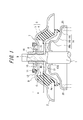
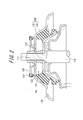
- FIG. 1 is a longitudinal sectional view including a central axis of a strut rod, showing an embodiment of the present invention. It is a longitudinal cross-sectional view including the central axis line of the strut rod showing a conventional mounting structure.
- reference numeral 1 denotes a strut rod extending from the wheel side
- 2 denotes a vehicle body side panel for mounting the strut rod
- 3 denotes a strut rod 1 and a vehicle body side panel 2.
- Each of the strut mounts interposed therebetween is shown.
- the strut mount 3 has a cylindrical body 4 made of a rigid material such as a metal material having a tapered shape that expands toward the lower side of the central axis, and vulcanization adhesion to the outer peripheral surface of the cylindrical body 4 over the entire circumference.
- the figure is provided with a cylindrical rubber elastic body 5 having an outer surface substantially parallel to the tapered shape of the cylindrical body 4, which is fixed by, for example.
- the strut rod 1 is inserted into the cylindrical body 4, and a rubber elastic body 5 is fitted inside an upward recess 6 provided in the vehicle body side panel 2. And the vehicle body side panel 2.
- the strut rod 1 receives an upward bound load from the wheel side and moves upward when the vehicle is traveling. After the displacement, the strut mount 3 may come out from the inside of the recess 6 of the vehicle body side panel 2 due to a large rebound displacement of the strut rod 1 downward, in order to prevent such displacement.
- An annular rigid member 10 having a larger planar contour size than the through hole 8 is attached to the upper end portion 9 of the strut rod 1 projecting upward from the through hole 8 provided in the hollow top wall 7 of the vehicle body side panel 2.
- An annular elastic stopper member 11 projecting downward is provided on the outer peripheral edge of the rigid member 10 so that the annular rigid member 10 and the elastic member are elastic.
- the elastic stopper member 11 is arranged so that at least a part of the elastic stopper member 11 enters the inside of the recess 12 together with a part of the annular rigid member 10 in the illustrated posture in which the weight of the vehicle body acts.
- the relative height of the rebound stopper with respect to the cylindrical body 4 is increased due to the provision of the annular rigid member 10 and the elastic stopper member 11 as the rebound stopper on the upper side of the hollow top wall 7 of the vehicle body side panel 2.
- the height H of the upper end portion of the elastic stopper member 11 from the upper end position of the cylindrical body 4 is made sufficiently low.
- the bonnet provided above the rebound stopper can be disposed at a low position, and reduction of air resistance during traveling can be achieved. it can.
- the elastic stopper member 11 Even when the elastic stopper member 11 is arranged in this way, the elastic stopper member 11 abuts against the bottom surface of the recess 12 under the backup by the annular rigid member 10 when the strut rod 1 is rebounded.
- the annular rigid member 10 and the elastic stopper member 11 function effectively as a rebound stopper, and the displacement of the strut mount 3 from the recess 6 of the vehicle body side panel 2 can be reliably prevented.
- the elastic stopper member 11 provided on the outer peripheral edge of the annular rigid member 10 is disposed above the vehicle body side panel 2 so that at least a part of the elastic stopper member 11 enters the inside of the recess 12.
- the elastic stopper member 11 is positioned on the lower side of the top edge B, and the elastic stopper member 11 is positioned on the lower side of the top edge B.
- the recessed part 12 provided in the hollow top wall 7 of the vehicle body side panel 2 deforms only a part of the peripheral part of the through hole 8 to the cylindrical body 4 side, and one or a plurality of parts in the circumferential direction of the peripheral part, For example, four locations can be provided.
- the elastic stopper member 11 is provided so as to protrude downward at a position corresponding to the location of the recess 12 on the outer peripheral edge of the annular rigid member 10. At least a part of the elastic stopper member 11 is allowed to enter inside the corresponding recess 12 in a posture in which the weight is applied.
- the elastic stopper member 11 is disposed in advance in contact with the bottom surface of the recess 12 in a posture in which the weight of the vehicle body acts, but the elastic stopper member is disposed in the same posture in the bottom surface of the recess 12. Therefore, they can be spaced apart at a required interval.
- the elastic stopper member 11 can be formed of a resin material such as a rubber material or a thermoplastic elastomer, for example.
- the cylindrical body 4 of the strut mount 3 is continuously connected to the tapered portion 4a whose diameter increases toward the lower side of the central axis and the peripheral edge of the tapered portion 4a on the upper side of the central axis. It forms with the inward flange part 4b which protrudes to the circumferential side.
- a thrust bearing 13 having a cylindrical portion 13a protruding downward is disposed on the lower surface side of the inward flange portion 4b of the cylindrical body 4, and the cylindrical portion 13a is disposed below the thrust bearing 13.
- the bracket 14 is attached, and the strut rod 1 is inserted into each of the thrust bearing 13 and the bracket 14.
- the enlarged diameter end of the bracket 14 on the lower end side in the drawing functions as a spring, in this case, a spring seat for a coil spring, as shown by a virtual line 20 in the drawing.
- the bracket 14 includes a cylindrical portion 14a having a substantially cylindrical shape with an upper end wall formed with a hole surrounding the cylindrical portion 13a of the thrust bearing 13 and having a diameter slightly reduced downward in the figure.
- 14a which is formed continuously with the peripheral edge on the lower end side of 14a, and has a tapered cylindrical portion 14b which expands in the downward direction in the figure, and is substantially inverted with the cross section shown in the figure formed continuously with the peripheral edge on the lower end side of the tapered cylindrical portion 14b.
- An L-shaped cylindrical flange portion 14c is provided.
- the lower female screw member 15 is screwed into a male screw portion that forms a part of the upper end portion 9 of the strut rod 1 and has a smaller diameter than the other portions, and the lower female screw member 15 is tightened.
- the inward flange portion 4b of the cylindrical body 4 is sandwiched and fixed between the lower female screw member 15 and the large diameter portion of the strut rod 1, and the upper female screw member 16 is screwed onto the male screw portion.
- the annular rigid member 10 is fastened and fixed between the lower female screw member 15 and the upper female screw member 16.
- the strut rod 1 is indirectly attached to the vehicle body side panel 2 via the strut mount 3.
Landscapes
- Engineering & Computer Science (AREA)
- Mechanical Engineering (AREA)
- Vehicle Body Suspensions (AREA)
- Fluid-Damping Devices (AREA)
- Springs (AREA)
Abstract
中心軸線の下方側に向けて拡径するテーパ形状を有する筒体(4)と、該筒体(4)の外周面に全周にわたって固着させたゴム弾性体(5)とを具えるストラットマウント(3)を介して、ストラットロッド(1)を車体側パネル(2)に取付ける構造であって、ストラットロッド(1)を筒体(4)に貫通させるとともに、車体側パネル(2)に設けた上方側への窪み(6)の内側にゴム弾性体(5)を嵌め合わせ、該車体側パネル(2)の前記窪み(6)の頂壁(7)に形成した貫通孔(8)から上方へ突出させたストラットロッド上端部分(9)に、該貫通孔(8)より平面輪郭寸法の大きい環状剛性部材(10)を取り付け、車体側パネル(2)の窪み頂壁(7)に、前記貫通孔(8)の周縁部分の一部もしくは全体を前記筒体(4)側に変形させてなる凹部(12)を設け、環状剛性部材(10)の外周縁に、前記凹部(12)の底面に当接して、前記環状剛性部材(10)との共働下で、ストラットロッド(1)の下方側への変位を規制する弾性ストッパ部材(11)を、下方側に突出させて設け、車体重量が作用した姿勢で、弾性ストッパ部材(11)の少なくとも一部を、車体側パネル(2)の前記凹部(12)の内側に入り込ませてなる。
Description
この発明は、車輪側から延びるストラットロッドを、ストラットマウントを介して車体側パネルに取付ける構造に関するものであり、とくに、そのような取付け構造を採用する車両のボンネットを低い位置に設定して、車両走行時の空気抵抗の軽減等を実現する技術を提案するものである。
車輪側に配設されるショックアブソーバの上方側部分を構成するストラットロッドは一般に、特許文献1~4に記載されているように、ゴム弾性体を有するストラットマウントを介して車体側パネルに取付けられる。
かかる取付け構造によれば、車両の走行に際し、車輪が路面から受ける上下方向の入力の、ショックアブソーバとその周囲のコイルスプリングとで吸収できなかった部分を、ストラットマウントのゴム弾性体の剪断変形によって吸収して、車輪側からの入力振動の、車体側への伝達を抑制することができる。
かかる取付け構造によれば、車両の走行に際し、車輪が路面から受ける上下方向の入力の、ショックアブソーバとその周囲のコイルスプリングとで吸収できなかった部分を、ストラットマウントのゴム弾性体の剪断変形によって吸収して、車輪側からの入力振動の、車体側への伝達を抑制することができる。
図2に例示する構造は、中心軸線の下方側に向けて拡径するテーパ形状を有する筒体101と、筒体101の外周面に全周にわたって固着させた筒状のゴム弾性体102とを具えるストラットマウント100を介して、ストラットロッド110を車体側パネル120に取付けるものであり、図2に示すところでは、ストラットロッド110を、ストラットマウント100の筒体101に貫通させるとともに、ストラットマウント100のゴム弾性体102を、車体側パネル120に設けた上方側への窪み121の内側に嵌め合わせている。
このように、ストラットマウント100を、車体側パネル120に連結固定することなく、単に、車体側パネル120の窪み121内に嵌め合わせただけの取付け構造では、ストラットロッド110が、車輪側からの上向きの入力を受けて上方側に大きく変位した後に、ストラットロッド110の、下方側への跳ね返り変位が生じた場合、ストラットマウント100が、車体側パネル120の窪み121から抜け出るおそれがあるので、これに対処するため、車体側パネル120の窪み頂壁122に形成した貫通孔123から上方側に突出するストラットロッド110の上端部分111に、貫通孔123よりも平面輪郭寸法が大きい環状剛性部材130を取付けるとともに、この環状剛性部材130の外周縁に、下方側に突出する弾性ストッパ部材131を、窪み頂壁122の上面への、接触もしくは非接触姿勢で設けることとし、これらの部材を、いわゆるリバウンドストッパとして機能させて、ストラットマウント100の、車体側パネル120からの離隔変位を拘束することとしている。
すなわち、ストラットロッド110が、それの上端部分111に取り付けた環状剛性部材130とともに下方側に変位した際には、弾性ストッパ部材131が、環状剛性部材130によるバックアップの下で、車体側パネル120の窪み頂壁122の上面に当接することになるので、環状剛性部材130および弾性ストッパ部材131により、ストラットロッド110の跳ね返り変位を規制して、ストラットマウント100の抜け出しを防止することができる。
すなわち、ストラットロッド110が、それの上端部分111に取り付けた環状剛性部材130とともに下方側に変位した際には、弾性ストッパ部材131が、環状剛性部材130によるバックアップの下で、車体側パネル120の窪み頂壁122の上面に当接することになるので、環状剛性部材130および弾性ストッパ部材131により、ストラットロッド110の跳ね返り変位を規制して、ストラットマウント100の抜け出しを防止することができる。
ところで、近年は、ストラットロッドと車体側パネルとの間に、ストラットマウントを介装させる上記の取付け構造を採用する車両で、走行時の空気抵抗の軽減、歩行者保護等の観点から、ボンネットを低い位置に配置することが希求されているも、上述したような、ストラットロッド110の取付け構造では、車体側パネル120の頂壁122の上方側に、リバウンドストッパを構成する環状剛性部材130および、該剛性環状弾性130の隆起平坦域の外周縁に取り付けた弾性ストッパ部材131を配設することとしているため、リバウンドストッパの配設高さ、より詳細には、弾性ストッパ部材131の上端部の、筒体101の上端位置からの高さHpが高くなり、これがため、弾性ストッパ部材131の上方に配置される、車両のボンネットの位置を、要求されるほどに十分低くすることができなかった。
この発明は、従来技術が抱えるこのような問題を解決することを課題とするものであり、それの目的とするところは、車体側パネルの上方側に設けるリバウンドストッパの、筒体に対する相対高さを低くして、車両のボンネットの、より低い位置への配設を可能にした、ストラットロッドの、車体側パネルへの取付け構造を提供するにある。
この発明の、ストラットロッドの、車体側パネルへの取付け構造は、中心軸線の下方側に向けて拡径するテーパ形状を有する筒体と、該筒体の外周面に全周にわたって固着させたゴム弾性体とを具えるストラットマウントを介して、ストラットロッドを車体側パネルに取付ける構造であって、
ストラットロッドを、ストラットマウントの筒体に貫通させるとともに、車体側パネルに設けた上方側への窪みの内側に、ストラットマウントのゴム弾性体を嵌め合わせ、該車体側パネルの前記窪みの頂壁に形成した貫通孔から上方へ突出させたストラットロッドの上端部分に、該貫通孔より平面輪郭寸法の大きい環状剛性部材を取り付け、
車体側パネルの窪み頂壁に、前記貫通孔の周縁部分の一部もしくは全体を前記筒体側に変形させてなる凹部を設け、環状剛性部材の外周縁に、前記凹部の底面に当接して、前記環状剛性部材との共働下で、ストラットロッドの下方側への変位を規制する弾性ストッパ部材を、下方側に突出させて設け、車体重量が作用した姿勢で、弾性ストッパ部材の少なくとも一部を、車体側パネルの前記凹部の内側に入り込ませてなるものである。
この発明の、ストラットロッドの、車体側パネルへの取付け構造によれば、先に述べたような、ストラットロッドの、下方側への跳ね返り変位に際する、弾性ストッパ部材の、車体側パネルへの当接箇所を、車体側パネルの窪み頂壁に設けた凹部の底面とし、車体重量が作用した姿勢で、弾性ストッパ部材の少なくとも一部を、前記凹部の内側に入り込ませることにより、環状剛性部材と弾性ストッパ部材とで構成されるリバウンドストッパの、筒体の上端位置に対する高さを、車体側パネルの窪み頂壁に凹部を有しない従来の取付け構造に比して低くすることができるので、この発明の取付け構造を採用する車両のボンネットを、十分低い位置に設定することができ、この結果として、車両走行時の空気抵抗の軽減や、歩行者保護等を実現することができる。
図1に示すところにおいて、図中1は、車輪側から延びるストラットロッドを、また、2は、ストラットロッド1を取付ける車体側パネルを、そして、3は、ストラットロッド1と車体側パネル2との間に介装したストラットマウントをそれぞれ示す。
ここで、ストラットマウント3は、中心軸線の下方に向けて拡径するテーパ形状を有する、金属材料等の剛性材料からなる筒体4と、筒体4の外周面に全周にわたって、加硫接着等により固着させた、図では、筒体4のテーパ形状に略平行な外表面を有する筒状のゴム弾性体5とを具えてなる。
図示のこのストラットマウント3は、ストラットロッド1を筒体4に挿入するとともに、車体側パネル2に設けた上方側への窪み6の内側に、ゴム弾性体5を嵌め合わせることにより、ストラットロッド1と車体側パネル2との間に介装させる。
図示のこのストラットマウント3は、ストラットロッド1を筒体4に挿入するとともに、車体側パネル2に設けた上方側への窪み6の内側に、ゴム弾性体5を嵌め合わせることにより、ストラットロッド1と車体側パネル2との間に介装させる。
ここにおいて、上述したような、ストラットマウント3を車体側パネル2に嵌め合わせただけの取付け構造では、車両の走行に際して、ストラットロッド1が、車輪側からの上向きのバウンド荷重を受けて上方側に変位した後に、ストラットロッド1の、下方側への大きな跳ね返り変位に起因して、ストラットマウント3が、車体側パネル2の窪み6の内側から抜け出ることがあることから、かかる抜け出し変位を防止するため、車体側パネル2の窪み頂壁7に設けた貫通孔8から上方へ突出させたストラットロッド1の上端部分9に、貫通孔8より大きい平面輪郭寸法を有する環状剛性部材10を取り付けるとともに、環状剛性部材10の外周縁に、下方側に突出する環状の弾性ストッパ部材11を設けて、環状剛性部材10および弾性ストッパ部材11を、ストラットロッド1の、下方側への余剰変位を規制するリバウンドストッパとして機能させる。
そしてこの発明では、車体側パネル2の窪み頂壁7に、図1に示すように、たとえば、貫通孔8の周縁部分を全周にわたって筒体4側に変形させてなる凹部12を形成するとともに、車体重量が作用した図示の姿勢で、弾性ストッパ部材11の少なくとも一部を、好ましくは、環状剛性部材10の一部とともに、前記凹部12の内側に入り込ませて弾性ストッパ部材11を配置することで、リバウンドストッパとしての環状剛性部材10および弾性ストッパ部材11を、車体側パネル2の窪み頂壁7の上方側に設けることに起因して高くなる、リバウンドストッパの、筒体4に対する相対高さ、つまり、弾性ストッパ部材11の上端部の、筒体4の上端位置からの高さHを十分低くする。
このことにより、この発明の取付け構造を採用する車両で、リバウンドストッパの上方側に設けるボンネットを、低い位置に配置することが可能になって、走行時の空気抵抗の軽減等を達成することができる。
このことにより、この発明の取付け構造を採用する車両で、リバウンドストッパの上方側に設けるボンネットを、低い位置に配置することが可能になって、走行時の空気抵抗の軽減等を達成することができる。
弾性ストッパ部材11をこのように配置した場合であっても、ストラットロッド1の跳ね返り変位に際し、弾性ストッパ部材11が、環状剛性部材10によるバックアップの下で、凹部12の底面に当接することにより、環状剛性部材10および弾性ストッパ部材11が、リバウンドストッパとして有効に機能して、ストラットマウント3の、車体側パネル2の窪み6からの抜け出し変位を確実に防止することができる。
なおここでは、図示の姿勢で、弾性ストッパ部材11の少なくとも一部を、凹部12の内側に入り込ませるため、環状剛性部材10の外周縁に設ける弾性ストッパ部材11を、車体側パネル2の、上方へ最も高く突出する頂縁Bの内周側に位置させるとともに、弾性ストッパ部材11の、少なくとも最下部を、前記頂縁Bよりも下方側に位置させている。
なおここでは、図示の姿勢で、弾性ストッパ部材11の少なくとも一部を、凹部12の内側に入り込ませるため、環状剛性部材10の外周縁に設ける弾性ストッパ部材11を、車体側パネル2の、上方へ最も高く突出する頂縁Bの内周側に位置させるとともに、弾性ストッパ部材11の、少なくとも最下部を、前記頂縁Bよりも下方側に位置させている。
なお、車体側パネル2の窪み頂壁7に設ける凹部12は、貫通孔8の周縁部分の一部だけを筒体4側に変形させて、該周縁部分の周方向に一箇所または複数箇所、たとえば4箇所設けることもできるが、この場合は、弾性ストッパ部材11を、環状剛性部材10の外周縁の、前記凹部12の配設箇所と対応する位置で下方側に突出させて設けて、車体重量が作用した姿勢で、弾性ストッパ部材11の少なくとも一部を、対応する凹部12の内側に入り込ませる。
図1に示すところでは、弾性ストッパ部材11を、車体重量が作用した姿勢で、凹部12の底面に予め接触させて配置しているが、弾性ストッパ部材は、同様の姿勢で、凹部12の底面から、所要の間隔をおいて離隔させて配置することもできる。
ここで、弾性ストッパ部材11は、たとえば、ゴム材料または、熱可塑性エラストマー等の樹脂材料にて形成することができる。
ここで、弾性ストッパ部材11は、たとえば、ゴム材料または、熱可塑性エラストマー等の樹脂材料にて形成することができる。
なお、図1では、ストラットマウント3の筒体4を、中心軸線の下方側に向けて拡径するテーパ状部分4aと、テーパ状部分4aの、中心軸線の上方側の周縁に連続して内周側へ突出する内向きフランジ部分4bとで形成している。
そしてここでは、筒体4の内向きフランジ部4bの下面側に、下方に向けて突出する筒部13aを具えたスラストベアリング13を配置するとともに、このスラストベアリング13の下方に、前記筒部13aを取り囲んで、ブラケット14を取付けて、これらのスラストベアリング13およびブラケット14のそれぞれの内部に、ストラットロッド1を挿通配置している。
ところで、ブラケット14の、図の下端側の拡径端は、図に仮想線20で示すように、ショックアブソーバと並列に配置されるスプリング、ここではコイルスプリングのばね座として機能する。
そしてここでは、筒体4の内向きフランジ部4bの下面側に、下方に向けて突出する筒部13aを具えたスラストベアリング13を配置するとともに、このスラストベアリング13の下方に、前記筒部13aを取り囲んで、ブラケット14を取付けて、これらのスラストベアリング13およびブラケット14のそれぞれの内部に、ストラットロッド1を挿通配置している。
ところで、ブラケット14の、図の下端側の拡径端は、図に仮想線20で示すように、ショックアブソーバと並列に配置されるスプリング、ここではコイルスプリングのばね座として機能する。
ここにおいて、ブラケット14は、スラストベアリング13の筒部13aを取り囲む孔を形成した上端壁付きの、図の下方に向けて僅かに縮径する略円筒状をなす筒状部分14aと、筒状部分14aの下端側の周縁に連続させて形成した、図の下方に向けて拡径するテーパ筒部分14bと、テーパ筒部分14bの下端側の周縁に連続させて形成した、図示の断面で略倒立L字状の筒状フランジ部分14cとを具えてなる。
またここでは、ストラットロッド1の上端部分9の一部を形成する、他の部分に比して小径の雄ねじ部に、下側雌ねじ部材15を螺合させるとともに、その下側雌ねじ部材15の締込みによって、筒体4の内向きフランジ部分4bを、下側雌ねじ部材15と、ストラットロッド1の大径部の間に挟み込んで固定し、併せて、前記雄ねじ部に、上側雌ねじ部材16を螺合させて、前記下側雌ねじ部材15とその上側雌ねじ部材16との間に、環状剛性部材10を締込み固定する。
以上に述べたようにして、ストラットロッド1は、ストラットマウント3を介して車体側パネル2に、間接的に取付けられることになる。
以上に述べたようにして、ストラットロッド1は、ストラットマウント3を介して車体側パネル2に、間接的に取付けられることになる。
1 ストラットロッド
2 車体側パネル
3 ストラットマウント
4 筒体
5 ゴム弾性体
6 窪み
7 頂壁
8 貫通孔
9 ストラットロッド上端部分
10 環状剛性部材
11 弾性ストッパ部材
12 凹部
13 スラストベアリング
13a 筒部
14 ブラケット
15 下側雌ねじ部材
16 上側雌ねじ部材
20 コイルスプリング
H リバウンドストッパの配設高さ
B 車体側パネルの頂縁
2 車体側パネル
3 ストラットマウント
4 筒体
5 ゴム弾性体
6 窪み
7 頂壁
8 貫通孔
9 ストラットロッド上端部分
10 環状剛性部材
11 弾性ストッパ部材
12 凹部
13 スラストベアリング
13a 筒部
14 ブラケット
15 下側雌ねじ部材
16 上側雌ねじ部材
20 コイルスプリング
H リバウンドストッパの配設高さ
B 車体側パネルの頂縁
Claims (1)
- 中心軸線の下方側に向けて拡径するテーパ形状を有する筒体と、該筒体の外周面に全周にわたって固着させたゴム弾性体とを具えるストラットマウントを介して、ストラットロッドを車体側パネルに取付ける構造であって、
ストラットロッドを、ストラットマウントの筒体に貫通させるとともに、車体側パネルに設けた上方側への窪みの内側に、ストラットマウントのゴム弾性体を嵌め合わせ、該車体側パネルの前記窪みの頂壁に形成した貫通孔から上方へ突出させたストラットロッドの上端部分に、該貫通孔より平面輪郭寸法の大きい環状剛性部材を取り付け、
車体側パネルの窪み頂壁に、前記貫通孔の周縁部分の一部もしくは全体を前記筒体側に変形させてなる凹部を設け、環状剛性部材の外周縁に、前記凹部の底面に当接して、前記環状剛性部材との共働下で、ストラットロッドの下方側への変位を規制する弾性ストッパ部材を、下方側に突出させて設け、車体重量が作用した姿勢で、弾性ストッパ部材の少なくとも一部を、車体側パネルの前記凹部の内側に入り込ませてなる、ストラットロッドの、車体側パネルへの取付け構造。
Applications Claiming Priority (2)
| Application Number | Priority Date | Filing Date | Title |
|---|---|---|---|
| JP2011-086257 | 2011-04-08 | ||
| JP2011086257A JP2012218574A (ja) | 2011-04-08 | 2011-04-08 | ストラットロッドの、車体側パネルへの取付け構造 |
Publications (1)
| Publication Number | Publication Date |
|---|---|
| WO2012137507A1 true WO2012137507A1 (ja) | 2012-10-11 |
Family
ID=46968916
Family Applications (1)
| Application Number | Title | Priority Date | Filing Date |
|---|---|---|---|
| PCT/JP2012/002384 Ceased WO2012137507A1 (ja) | 2011-04-08 | 2012-04-05 | ストラットロッドの、車体側パネルへの取付け構造 |
Country Status (2)
| Country | Link |
|---|---|
| JP (1) | JP2012218574A (ja) |
| WO (1) | WO2012137507A1 (ja) |
Cited By (1)
| Publication number | Priority date | Publication date | Assignee | Title |
|---|---|---|---|---|
| CN103982581A (zh) * | 2014-05-09 | 2014-08-13 | 徐工集团工程机械股份有限公司 | 一种防脱防腐的剪切型金属橡胶隔振器 |
Families Citing this family (1)
| Publication number | Priority date | Publication date | Assignee | Title |
|---|---|---|---|---|
| CN105216804A (zh) * | 2015-10-30 | 2016-01-06 | 南车戚墅堰机车有限公司 | 抗振型传动机构安装座 |
Citations (4)
| Publication number | Priority date | Publication date | Assignee | Title |
|---|---|---|---|---|
| FR2513334A1 (fr) * | 1981-09-24 | 1983-03-25 | Nadella | Butee axiale et radiale combinee |
| FR2759752A1 (fr) * | 1997-02-19 | 1998-08-21 | Hutchinson | Attache non porteuse pour ensemble ressort-amortisseur de vehicule automobile |
| JP2004232824A (ja) * | 2003-01-31 | 2004-08-19 | Tokai Rubber Ind Ltd | ストラットマウント |
| JP2010285037A (ja) * | 2009-06-10 | 2010-12-24 | Bridgestone Corp | ストラットマウント |
-
2011
- 2011-04-08 JP JP2011086257A patent/JP2012218574A/ja active Pending
-
2012
- 2012-04-05 WO PCT/JP2012/002384 patent/WO2012137507A1/ja not_active Ceased
Patent Citations (4)
| Publication number | Priority date | Publication date | Assignee | Title |
|---|---|---|---|---|
| FR2513334A1 (fr) * | 1981-09-24 | 1983-03-25 | Nadella | Butee axiale et radiale combinee |
| FR2759752A1 (fr) * | 1997-02-19 | 1998-08-21 | Hutchinson | Attache non porteuse pour ensemble ressort-amortisseur de vehicule automobile |
| JP2004232824A (ja) * | 2003-01-31 | 2004-08-19 | Tokai Rubber Ind Ltd | ストラットマウント |
| JP2010285037A (ja) * | 2009-06-10 | 2010-12-24 | Bridgestone Corp | ストラットマウント |
Cited By (2)
| Publication number | Priority date | Publication date | Assignee | Title |
|---|---|---|---|---|
| CN103982581A (zh) * | 2014-05-09 | 2014-08-13 | 徐工集团工程机械股份有限公司 | 一种防脱防腐的剪切型金属橡胶隔振器 |
| CN103982581B (zh) * | 2014-05-09 | 2016-02-10 | 徐工集团工程机械股份有限公司 | 一种防脱防腐的剪切型金属橡胶隔振器 |
Also Published As
| Publication number | Publication date |
|---|---|
| JP2012218574A (ja) | 2012-11-12 |
Similar Documents
| Publication | Publication Date | Title |
|---|---|---|
| JP6435741B2 (ja) | バンプストッパキャップ | |
| US20190154097A1 (en) | Stopper for transmission mount | |
| KR102453592B1 (ko) | Tm마운트의 스토퍼 | |
| US10532622B2 (en) | Suspension device | |
| JP2018105492A (ja) | スプリングシート構造 | |
| CN102514460B (zh) | 一种分离缓冲型减振器支柱及汽车 | |
| JP2012218574A (ja) | ストラットロッドの、車体側パネルへの取付け構造 | |
| CN106494517A (zh) | 一种带限位装置的驾驶室后悬置 | |
| JP5965274B2 (ja) | 車体側パネルへのストラットロッドの取付構造 | |
| JP5327141B2 (ja) | サスペンション装置 | |
| JP5893844B2 (ja) | ストラットマウントならびに、ストラットロッドの、車体側パネルへの取付け構造 | |
| KR101165050B1 (ko) | 쇽업소버의 상부 장착구조 | |
| KR102417402B1 (ko) | 차량의 스트럿 어셈블리 | |
| JP2004232824A (ja) | ストラットマウント | |
| CN207349335U (zh) | 一种车身悬置 | |
| KR102474609B1 (ko) | 자동차 현가장치용 스프링 패드 및 그것을 포함하는 현가장치 | |
| CN106285248A (zh) | 一种锁钩组件、锁止机构及汽车 | |
| CN206268360U (zh) | 一种减振器顶胶及顶胶安装结构 | |
| KR20130017601A (ko) | 서브프레임의 장착구조 | |
| CN203272590U (zh) | 汽车减震器顶胶装置 | |
| CN202608501U (zh) | 一种分离缓冲型减振器支柱及汽车 | |
| KR102463448B1 (ko) | 인슐레이터 유닛의 장착구조 | |
| CN206465722U (zh) | 一种副簧托架总成 | |
| KR101372926B1 (ko) | 서스펜션용 인슐레이터 | |
| CN104070955B (zh) | 一种用于固定汽车减震器的支撑装置 |
Legal Events
| Date | Code | Title | Description |
|---|---|---|---|
| 121 | Ep: the epo has been informed by wipo that ep was designated in this application |
Ref document number: 12768013 Country of ref document: EP Kind code of ref document: A1 |
|
| NENP | Non-entry into the national phase |
Ref country code: DE |
|
| 122 | Ep: pct application non-entry in european phase |
Ref document number: 12768013 Country of ref document: EP Kind code of ref document: A1 |