WO2012133864A1 - マーキング方法、欠陥を有する対象物にマーキングを行うための装置および防眩処理用金型の欠陥検出システム - Google Patents
マーキング方法、欠陥を有する対象物にマーキングを行うための装置および防眩処理用金型の欠陥検出システム Download PDFInfo
- Publication number
- WO2012133864A1 WO2012133864A1 PCT/JP2012/058768 JP2012058768W WO2012133864A1 WO 2012133864 A1 WO2012133864 A1 WO 2012133864A1 JP 2012058768 W JP2012058768 W JP 2012058768W WO 2012133864 A1 WO2012133864 A1 WO 2012133864A1
- Authority
- WO
- WIPO (PCT)
- Prior art keywords
- marking
- mask
- spray gun
- defect
- ink
- Prior art date
- Legal status (The legal status is an assumption and is not a legal conclusion. Google has not performed a legal analysis and makes no representation as to the accuracy of the status listed.)
- Ceased
Links
Images




Classifications
-
- G—PHYSICS
- G01—MEASURING; TESTING
- G01N—INVESTIGATING OR ANALYSING MATERIALS BY DETERMINING THEIR CHEMICAL OR PHYSICAL PROPERTIES
- G01N21/00—Investigating or analysing materials by the use of optical means, i.e. using sub-millimetre waves, infrared, visible or ultraviolet light
- G01N21/84—Systems specially adapted for particular applications
- G01N21/88—Investigating the presence of flaws or contamination
-
- B—PERFORMING OPERATIONS; TRANSPORTING
- B05—SPRAYING OR ATOMISING IN GENERAL; APPLYING FLUENT MATERIALS TO SURFACES, IN GENERAL
- B05D—PROCESSES FOR APPLYING FLUENT MATERIALS TO SURFACES, IN GENERAL
- B05D5/00—Processes for applying liquids or other fluent materials to surfaces to obtain special surface effects, finishes or structures
- B05D5/06—Processes for applying liquids or other fluent materials to surfaces to obtain special surface effects, finishes or structures to obtain multicolour or other optical effects
-
- B—PERFORMING OPERATIONS; TRANSPORTING
- B41—PRINTING; LINING MACHINES; TYPEWRITERS; STAMPS
- B41M—PRINTING, DUPLICATING, MARKING, OR COPYING PROCESSES; COLOUR PRINTING
- B41M5/00—Duplicating or marking methods; Sheet materials for use therein
-
- B—PERFORMING OPERATIONS; TRANSPORTING
- B05—SPRAYING OR ATOMISING IN GENERAL; APPLYING FLUENT MATERIALS TO SURFACES, IN GENERAL
- B05D—PROCESSES FOR APPLYING FLUENT MATERIALS TO SURFACES, IN GENERAL
- B05D1/00—Processes for applying liquids or other fluent materials
- B05D1/02—Processes for applying liquids or other fluent materials performed by spraying
-
- B—PERFORMING OPERATIONS; TRANSPORTING
- B05—SPRAYING OR ATOMISING IN GENERAL; APPLYING FLUENT MATERIALS TO SURFACES, IN GENERAL
- B05D—PROCESSES FOR APPLYING FLUENT MATERIALS TO SURFACES, IN GENERAL
- B05D1/00—Processes for applying liquids or other fluent materials
- B05D1/32—Processes for applying liquids or other fluent materials using means for protecting parts of a surface not to be coated, e.g. using stencils, resists
-
- B—PERFORMING OPERATIONS; TRANSPORTING
- B05—SPRAYING OR ATOMISING IN GENERAL; APPLYING FLUENT MATERIALS TO SURFACES, IN GENERAL
- B05D—PROCESSES FOR APPLYING FLUENT MATERIALS TO SURFACES, IN GENERAL
- B05D5/00—Processes for applying liquids or other fluent materials to surfaces to obtain special surface effects, finishes or structures
- B05D5/005—Repairing damaged coatings
Definitions
- the present invention relates to a marking method for an object having a defect and an apparatus for marking an object having a defect.
- the present invention also relates to a defect detection system for a mold for anti-glare treatment.
- An image display device such as a liquid crystal display, a plasma display panel, a cathode ray tube (CRT) display, or an organic electroluminescence (EL) display has a significant loss of visibility when external light is reflected on its display surface.
- display is performed using a television or personal computer that emphasizes image quality, a video camera or digital camera that is used outdoors with strong external light, and reflected light.
- a process for preventing external light from being reflected on the surface of the image display device is performed.
- the processing performed on the surface of such an image display device includes antireflection processing using interference by the optical multilayer film and prevention of blurring the reflected image by scattering incident light by forming fine irregularities on the surface. It is roughly divided into dazzling treatment.
- the former non-reflective treatment increases the cost because it is necessary to form a multilayer film having a uniform optical film thickness.
- anti-glare treatment can be performed relatively inexpensively, it is widely used for applications such as large personal computers and monitors.
- the anti-glare treatment of the image display device is typically performed by bonding an anti-glare film with anti-glare properties to the surface of the image display device.
- an anti-glare film for example, a resin solution in which fine particles are dispersed is applied on a base sheet by adjusting the film thickness, and the fine particles are exposed on the surface of the coating film so that random surface irregularities are formed on the base sheet. It is manufactured by the method of forming on top.
- the antiglare film manufactured using a resin solution in which such fine particles are dispersed has an influence on the arrangement and shape of surface irregularities depending on the dispersion state and application state of the fine particles in the resin solution.
- the antiglare property is expressed by the shape of the surface, so that no whitening due to the fine particles occurs. Furthermore, in the method of applying a resin added with fine particles, unevenness occurs due to fluctuations in the coating thickness, so precise coating thickness control has been required, but in the method of forming fine irregularities on the surface, the coating thickness Since the problem of unevenness due to fluctuation does not occur, it is possible to achieve excellent productivity.
- a method of transferring the irregularities of the mold onto the surface of an object (such as a transparent resin film) using a mold having a surface irregularity formed in advance is produced. It is particularly preferably used from the viewpoint of sex.
- the surface uneven shape of the mold is transferred, if there is a defect on the uneven surface of the mold, the defect continues to occur throughout the product (such as an antiglare film). Therefore, it is important that defects on the concave and convex surface of the mold are detected by a detection device, marking is performed on the detected defective portion, and removal or repair of the defective portion is performed using the marking as an index in a subsequent process.
- JP 2006-266981-A includes a defect marking apparatus that controls the extrusion and retraction of an oil-based marking pen and marks the defective portion of a sheet-like product with the pen tip of the oil-based marking pen. Is disclosed.
- the defect marking apparatus described in JP 2006-26698-A performs marking by bringing a pen tip into contact with an object to be marked. Therefore, some objects may be damaged by contact with the pen tip.
- the defect marking apparatus described in JP2006-266698-A uses a sheet-like product as a detection target, if a defect occurs, disposal may be more appropriate than repair. For example, in the case of an expensive product such as a mold, the defective portion is usually repaired. Therefore, a marking method that does not scratch is desired.
- the present invention relates to a marking method capable of marking with good visibility without damaging an object, an apparatus for marking an object having defects, and a defect detection system for a mold for anti-glare treatment
- the purpose is to provide.
- the present invention includes the following. [1] An arrangement step of arranging an object having a spray gun for ejecting ink droplets, a mask for shielding part of the ink droplets ejected from the spray gun, and in this order without contacting each other, and the spray A marking method for applying an ink droplet ejected from a gun onto the object through the mask and marking the object, and marking the object having a defect.
- the mask shields ink droplets in a front area centered on the front of the spray gun and allows at least a part of ink droplets outside the front area to pass.
- the object is The method according to [1], wherein the defect is arranged so as to be in an area corresponding to the front area.
- a spray gun that ejects ink droplets and a mask that blocks a part of the ink droplets ejected from the spray gun, and the spray gun and the mask are arranged without contacting an object.
- a device for marking a defective object is
- the mask shields ink droplets in a front area centered on the front surface of the spray gun and allows at least a part of ink droplets outside the front area to pass through.
- a defect detection system for an anti-glare treatment mold comprising: a detection device that detects a defect in the anti-glare treatment mold; and the device according to [6].
- the apparatus for marking an object having defects, and the defect detection system for the anti-glare mold the object having defects is marked using a spray gun.
- marking can be performed without contact, and therefore, it is possible to prevent the marking from causing scratches.
- marking is performed by combining a spray gun and a mask, excellent marking with excellent visibility can be performed.
- FIG. 1 It is a figure which shows the other example of the mask used with the method shown in FIG. It is a figure which shows the other example of the mask used with the method shown in FIG. It is a schematic perspective view which shows a preferable example of the defect detection system of the metal mold
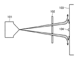
- FIG. 1 is a cross-sectional view showing a preferred example of a marking method for an object having defects according to the present invention.
- the method of the present invention is a method of marking an object having a defective portion using a marking device including a spray gun and a mask. Specifically, as shown in FIG. An arrangement step of disposing the spray gun 101 to be ejected, the mask 102 for shielding a part of the ink droplet 105 ejected from the spray gun 101, and the object 103 in this order without contact with each other; A marking step of applying an ink droplet on the object 103 through the mask 102 and marking the object 103.
- the mask 102 has an opening for allowing ink droplets to pass therethrough and a shielding portion for shielding ink droplets.
- the mask 102 has an opening that allows ink droplets to pass through a front area centered on the front direction of the spray gun 101, and a peripheral area of the opening serves as a shield that blocks ink drops.
- the defective portion 104 of the target object 103 corresponds to the shielding portion of the mask 102 and is located near the region corresponding to the opening portion of the mask 102. By adopting such an arrangement relationship, ink adhesion to the defective portion 104 is suppressed, and the defective portion 104 can be clearly shown.
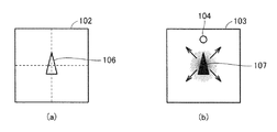
- FIG. 2A is a view showing a preferred example of the configuration of the mask used in the marking method shown in FIG.
- the mask 102 shown in FIG. 2A has a triangular opening 106 at the center.
- the mask shown in FIG. 2A is used by being arranged so that the position where the broken lines intersect with the front direction of the spray gun 101 (hereinafter also in the masks shown in FIG. 4A, FIG. 7 and FIG. 8). The same).
- FIG. 2B is a diagram schematically showing the marking formed on the object 103 when marking is performed using the mask 102 shown in FIG. As shown in FIG. 2B, a marking 107 is formed in a region corresponding to the opening 106 of the mask 102.
- the ink droplets that have passed through the opening of the mask 102 reach the object 103 in the direction of the arrow in FIG. Spread. Since the defect portion 104 on the object 103 is located above the region corresponding to the opening 106 of the mask 102, the positional relationship between the marking 107 on the object 103 and the defect portion 104 is as shown in FIG. ) As shown.
- FIG. 3 is a cross-sectional view showing another preferred example of the marking method of the present invention. As shown in FIG. 3, the marking method shown in FIG. 3 differs from the marking method shown in FIG. 1 in the configuration of the mask 102 and the positional relationship between the mask 102 and the defective portion 104.
- the mask 102 is formed with a shielding portion that shields ink droplets in a front area centered on the front surface of the spray gun 101, and a part of the peripheral area of the shielding portion is an opening that allows ink droplets to pass therethrough.
- the defective portion 104 of the object 103 is located in the shielding portion of the mask 102, that is, in a region corresponding to the front region. With such an arrangement relationship, ink adhesion to the defective portion 104 is suppressed, and marking surrounding the defective portion 104 is also possible, and the defective portion 104 can be clearly indicated by the marking.
- the shape of the marking on the target object 103 is a shape in which the shape of the opening of the mask 102 is diffused.
- the ink droplet diffusion direction is a direction away from the center as shown by an arrow in FIG. 3, and in the method shown in this embodiment, the defective portion 104 is at a position corresponding to the center of the mask 102, that is, the ink droplet diffusion direction. Therefore, it is possible to prevent ink from adhering to the defective portion 104.
- the size of the shielding portion at the center of the mask 102 may be determined according to the size of the defective portion 104 on the object. That is, the shielding range is preferably determined to a size that can prevent ink from adhering to the defective portion 104 due to the marking.
- FIG. 4A is a view showing a preferred example of the configuration of the mask used in the marking method shown in FIG.
- the mask 102 shown in FIG. 4A has a circular shielding portion at the center portion, and has an annular opening 106 surrounding the same.
- FIG. 4B is a diagram schematically showing the marking formed on the object 103 when marking is performed using the mask 102 shown in FIG. As shown in FIG. 4B, a marking is formed in a region corresponding to the opening 106 of the mask 102. Further, since there is a gap between the mask 102 and the object 103, the ink droplets that have passed through the opening of the mask 102 diffuse in the direction of the arrow in FIG. 4B before reaching the object 103. . Since the defective portion 104 on the target object 103 is located at the center of the mask 102, the positional relationship between the marking 107 on the target object 103 and the defective portion 104 is as shown in FIG.
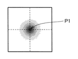
- FIG. 5 is a diagram showing how ink adheres to the mask. Since the ink adheres most at the position P1 corresponding to the front direction of the spray gun, the position where the ink adheres is the position corresponding to the front direction of the spray gun in the mask.
- the spray gun 101 atomizes the ink by the discharged air flow, and transports the ink droplet 105 to the target object 103 on the air flow.
- the spray gun 101 is not particularly limited as long as the opening of the mask 102 is included in the ink drop sending angle range and the ink drop can be sent out through the opening of the mask 102.
- the spray gun 101 is preferably provided with an ink valve that can be opened and closed to control the ejection timing of the ink droplets.
- FIG. 6 is a diagram illustrating a preferred example of an air circuit that controls the timing of ejecting ink droplets in the spray gun 101.
- the air supplied from the air pressure source 113 is separated into ink valve operating air supplied to the piston that opens the ink valve and atomizing air that atomizes the ink, and is sent to the electromagnetic valves 112 and 110, respectively.
- the electromagnetic valve 112 controls the supply of ink valve operating air
- the electromagnetic valve 110 controls the supply of atomized air.
- the speed controller 111 adjusts the flow rate of the atomized air.
- the opening time of the solenoid valve 112 that controls the supply of ink valve operating air depends on the ink used and the piping length of the pneumatic circuit.
- the opening of the electromagnetic valve 110 that controls the supply of atomizing air may be continuous, may be opened when the ink valve is opened, and may be closed when the ink valve is closed. It is more preferable to operate so that the air supply and the ink valve opening are interlocked with each other because silence and a reduction in air consumption can be realized.
- the supply of atomizing air is not continuous, it is preferable that the atomizing air is opened earlier than the ink valve is opened, and the atomizing air valve is closed later than the ink valve is closed. This suppresses ink dripping that occurs in the spray gun body.
- the ink droplets become finer, and as the flow rate decreases, the ink droplets increase. Appropriate ink drop sizes exist to clarify the marking outline. Therefore, it is preferable to have a mechanism for adjusting the flow rate of atomizing air, such as the speed controller 111, so that the ink droplet size can be adjusted to an appropriate size.
- any solenoid valve having three or more ports for residual pressure processing can be preferably used.
- a solenoid valve for example, model MDSYS-A sold by MISUMI Corporation can be used.
- MDSYS-A is a 5-port solenoid valve, but unnecessary ports can be closed and used.
- the speed controller 111 for example, a model SPJYS4 sold by MISUMI Corporation can be used.
- a spray gun having an ink valve that can be opened and closed as described above for example, a spray gun ST series manufactured by Fuso Seiki Co., Ltd. can be mentioned.
- the ST6 series capable of independently adjusting the atomizing air pressure and the ink valve opening / closing air pressure can be particularly preferably used.
- the opening time of the electromagnetic valve that supplies air to the piston that opens the ink valve is preferably 100 ms or longer. By setting it to 100 ms or longer, sufficient operation tracking can be performed.
- the mask is located between the spray gun and the marking target, and is located in the course of the ink droplets generated by the spray gun flying toward the marking target, and removes a part of the ink droplets ejected from the spray gun. Shield.
- Examples of the form include a plate, a thin plate, and a film having an opening.
- FIGS. 7A and 7B show an example of a mask used in such a form, which is different from the example shown in FIG.
- the mask 102 has a shielding portion at a position facing the front direction of the spray gun 101, and the defective portion 104 of the object 103 is in the front area.
- FIGS. 8A to 8F show examples of the mask used in such a form different from the example shown in FIG. 4A.
- an appropriate ink may be selected according to the marking object.
- the marking object is a metal
- Aero Ink # 245, Aero Ink # 1250, etc. sold by Union Corporation can be preferably used.
- Inks are roughly classified into dye-based inks and pigment-based inks, and dye-based inks are more preferable in the method of the present invention. This is because in the case of pigment-based ink, precipitation of the coloring material in the ink piping may occur.
- the marking object has an undesirable defect to be identified.
- the object include a plate made of a material such as metal, resin, and glass, a film, a cylinder, and a cylinder.
- the defects include voids, scratches, dents, and attached foreign matter.
- the size of the defect is not particularly limited, but is within a range of, for example, a diameter of about 40 ⁇ m to 3 mm.
- the method of the present invention is particularly useful in marking objects that may be damaged by contact.
- a mold for molding a large-area optical component is exemplified. Among them, it is particularly effective to perform marking according to the method of the present invention because the anti-glare mold for optical film molding has a high risk of its characteristics being impaired by contact of the marking mechanism.
- FIG. 9 is a schematic perspective view showing a preferred example of a defect detection system for an anti-glare treatment mold according to the present invention.
- the defect detection system shown in FIG. 9 is a system for detecting and marking defects in an anti-glare processing mold, and a mold 205 to be inspected and chucking posts 203 and 204 for fixing the mold 205.
- An inspection head 206 for acquiring an image of a partial region of the surface of the mold 205 to be inspected, a marking unit 208 for marking the surface of the mold 205 in a non-contact manner, and the inspection head 206 and the marking First moving means 207 and second moving means 202 for moving the position of the unit 208 on the surface of the mold 205 are provided. Further, a control unit 201 for controlling the inspection head 206, the marking unit 208, the first moving unit 207, and the second moving unit 202 is provided.
- the first moving means 207 is a moving means for moving the inspection head 206 and the marking unit 208 in the direction of arrow A with respect to the mold 205 while maintaining the relative positional relationship with each other.
- the second moving unit 202 is a moving unit that moves or rotates the mold 205 itself that is an inspection target.
- the chucking post 204 is movable and moves in the direction of arrow B according to the size of the mold 205.
- the marking unit 208 includes the spray gun and the mask shown in FIGS.
- the inspection head 206 includes an area image sensor or a linear image sensor, for example, and images the state of the mold surface.
- the control unit 201 has means for performing appropriate image processing on the obtained image, and can automatically detect a protrusion-like defect or a dent-like defect on the surface of the anti-glare processing mold.
- a defect detection apparatus is configured by 201.
- As an area image sensor for example, CV-H500C, CV-H500M, CV-H200C, CV-H200M, CV-H100C, CV-H100M manufactured by Keyence Corporation, or FZ-SC5M, FZ- manufactured by OMRON Corporation. S5M, FZ-SC2M, FZ-S2M and the like are exemplified.
- Examples of the linear image sensor include a CCD linear image sensor manufactured by Toshiba Corporation, a TCD series, and a color line sensor TLC-7500CLD manufactured by Takenaka System Equipment Co., Ltd.
- These sensors are generally used in combination with a lens.
- Various lenses can be selected from the focal length, magnification, and the like.
- the CA-LH series focal length 8 mm, 16 mm, 25 mm, 50 mm
- the CA-LM series optical magnification x0.5 to x1. 0, x2, x4, x6, x8) and the like can be used.
- the image obtained may be subjected to various image filters to reduce noise, enhance brightness change, or correct uneven illumination state.
- various filters include a shading correction filter, a contrast correction filter, a brightness correction filter, an intermediate value filter, and a blur filter.
- Each filtering process can be achieved by various known algorithms.
- the hardware for performing image filter processing is not particularly limited. For example, it may be realized by using a general-purpose computer such as a personal computer (also called a personal computer or a PC), or by using a dedicated image processing device. Also good. In addition, any device that can handle image data can be used without particular limitation. Examples of the dedicated image processing apparatus include hardware designed exclusively for CV-5000 series and CV-3000 series manufactured by Keyence Corporation, ZFX series and FZ3 series manufactured by OMRON Corporation.
- Examples of the first moving means 207 include a linear actuator that is a linear motion mechanism and a combination of this with a stepping motor, a servo motor, or a DC motor (for example, a servo linear actuator).
- various driving means such as a stepping motor, a servo motor, and a DC motor can be used.
- a stepping motor can be preferably used from the viewpoint of controllability of the movement amount.
- Various gears can be further combined depending on the accuracy and torque required.
- stepping motors include AS series and AR series
- examples of servo motors include NX series (both manufactured by Oriental Motor Co., Ltd.), and products in combination with gears can be obtained.
- Examples of the linear actuator include ESR series, EZSII series, and EZX series (all manufactured by Oriental Motor Co., Ltd.). These motors are general-purpose products, and similar products can be obtained from various companies.
- a method for detecting a defect using the defect detection system shown in FIG. The inspection head 206 and the marking unit 208 are moved by the first moving means 207, or the mold 205 is moved by the second moving means 202, and images of the respective positions on the surface of the mold 205 are sequentially acquired by the inspection head 206.
- the acquired image data is sent to the control unit 201, and the control unit 201 analyzes the image data to detect a defective portion on the surface of the mold 205.
- the marking unit 208 is controlled to mark the peripheral portion of the defect.
- a method for marking a peripheral portion of a defect can be performed by the above-described marking method according to the present invention.
- the marking object was an anti-glare mold with chrome plating.
- Aero ink “# 245 (blue)” (manufactured by Union Corporation) was introduced into the ink inlet of the spray gun “ST6SK” (manufactured by Fuso Seiki Co., Ltd.). Air of 0.5 MPa was supplied to the piston for driving the ink valve of the spray gun through a solenoid valve “MDSYS-A” (sold by MISUMI Corporation).
- atomized air was supplied to the spray gun via a solenoid valve “MDSYS-A” (sold from MISUMI Corporation) and a speed controller “SPJYS4” (sold from MISUMI Corporation).
- the solenoid valve was controlled by a personal computer using a USB digital input / output “DIO-8 / 8B-UBT” (manufactured by Y2 Co., Ltd.) via a terminal “SSR G3S4-D DC24” (manufactured by OMRON Corporation).
- the spray gun ink valve opening adjustment dial and the atomizing air flow rate were adjusted so that ink droplets were ejected in an appropriate size and in an appropriate amount.
- the atomizing air flow rate was finely adjusted with a speed controller.
- the ink valve opening time was then determined to control the amount of ink deposited on the marking object.
- appropriate marking can be realized by opening the solenoid valve for supplying the ink valve opening air for 400 ms.
- the supply of atomizing air is interlocked with the operation of the ink valve, and the electromagnetic valve that supplies atomizing air is turned ON 100 ms before the ink valve operating electromagnetic valve is turned ON, and 200 ms after the ink valve is closed.
- the solenoid valve connected to the atomizing air side was turned off.
- the mask was placed at a position 35 mm away from the spray gun outlet.
- the object was placed at a position 50 mm away from the spray gun outlet, with the defective portion corresponding to the front of the spray gun.
- a polypropylene film having a thickness of 200 ⁇ m provided with an opening was used as the mask.
- the shape of the opening was the shape shown in FIG.
- the inner diameter was 3 mm and the outer diameter was 5 mm.
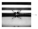
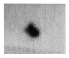
- FIG. 10 shows a photograph of the surface of an object that has been marked in Example 1.
- marking was performed by the method shown in FIG. 3 assuming that the position indicated by the point P2 in FIG. Although the marking diffuses in the direction indicated by the arrow in FIG. 10 (outside), the vicinity of the point P2 is not contaminated with ink, and a clear marking is provided around this.
- Example 2 Marking was performed in the same manner as in Example 1 except that a mask having a different opening shape was used and the object was placed at a position 40 mm away from the spray gun outlet.
- the shape of the opening of the mask was the shape shown in FIG.
- the size of the triangular opening shown in FIG. 2A is about 3 mm in height.
- FIG. 11 shows a photograph of the surface of an object that has been marked in Example 2. Although the marking according to Example 2 was more deformed than the marking according to Example 1, good marking was possible.
Landscapes
- Physics & Mathematics (AREA)
- Health & Medical Sciences (AREA)
- Life Sciences & Earth Sciences (AREA)
- Chemical & Material Sciences (AREA)
- Analytical Chemistry (AREA)
- Biochemistry (AREA)
- General Health & Medical Sciences (AREA)
- General Physics & Mathematics (AREA)
- Immunology (AREA)
- Pathology (AREA)
- Details Or Accessories Of Spraying Plant Or Apparatus (AREA)
- Application Of Or Painting With Fluid Materials (AREA)
- Nozzles (AREA)
- Investigating Materials By The Use Of Optical Means Adapted For Particular Applications (AREA)
Abstract
本発明は、インク滴を吐出するスプレーガン、スプレーガンから吐出されるインク滴の一部を遮蔽するマスク、及び欠陥を有する対象物をこの順に互いが接触することなく配置する配置工程と、スプレーガンより吐出されるインク滴をマスクを介して対象物上に塗布して対象物にマーキングを行なうマーキング工程と、を含む、欠陥を有する対象物へのマーキング方法である。本発明によれば、対象物に傷をつけることなく、かつ視認性良好なマーキングが可能なマーキング方法を提供できる。
Description
本発明は、欠陥を有する対象物へのマーキング方法、欠陥を有する対象物にマーキングを行なうための装置に関する。また、本発明は防眩処理用金型の欠陥検出システムに関する。
液晶ディスプレイ、プラズマディスプレイパネル、ブラウン管(陰極線管:CRT)ディスプレイ、有機エレクトロルミネッセンス(EL)ディスプレイなどの画像表示装置は、その表示面に外光が映り込むと視認性が著しく損なわれてしまう。従来、このような外光の映り込みを防止するために、画質を重視するテレビやパーソナルコンピュータ、外光の強い屋外で使用されるビデオカメラやデジタルカメラ、および反射光を利用して表示を行なう携帯電話などにおいては、画像表示装置の表面に外光の映り込みを防止するための処理が施されている。このような画像表示装置の表面に施される処理は、光学多層膜による干渉を利用した無反射処理と、表面に微細な凹凸を形成することにより入射光を散乱させて映り込み像をぼかす防眩処理とに大別される。前者の無反射処理は、均一な光学膜厚の多層膜を形成する必要があるため、コスト高になる。これに対して、後者の防眩処理は、比較的安価に行なうことができるため、大型のパーソナルコンピュータやモニタなどの用途に広く用いられている。
上記画像表示装置の防眩処理は、典型的には、画像表示装置の表面に、防眩性が付与された防眩フィルムを貼合することによりなされる。防眩フィルムは従来、たとえば、微粒子を分散させた樹脂溶液を、基材シート上に膜厚を調整して塗布し、該微粒子を塗布膜表面に露出させることでランダムな表面凹凸を基材シート上に形成する方法などにより製造されている。しかしながら、このような微粒子を分散させた樹脂溶液を用いて製造された防眩フィルムは、樹脂溶液中の微粒子の分散状態や塗布状態などによって表面凹凸の配置や形状が左右されてしまうため、意図したとおりの表面凹凸を得ることが困難であり、防眩フィルムのヘイズを低く設定する場合、十分な防眩効果が得られないという問題があった。さらに、このような従来の防眩フィルムを画像表示装置の表面に配置した場合、散乱光によって表示面全体が白っぽくなり、表示が濁った色になる、いわゆる「白ちゃけ」が発生しやすいという問題があった。また、最近の画像表示装置の高精細化に伴って、画像表示装置の画素と防眩フィルムの表面凹凸形状とが干渉し、その結果、輝度分布が発生して表示面が見えにくくなる、いわゆる「ギラツキ」現象が発生しやすいという問題もあった。ギラツキを解消するために、バインダー樹脂とこれに分散される微粒子との間に屈折率差を設けて光を散乱させる試みもあるが、そのような防眩フィルムを画像表示装置の表面に配置した際には、微粒子とバインダー樹脂との界面における光の散乱によって、コントラストが低下しやすいという問題もあった。
一方、微粒子を含有させずに、透明樹脂層の表面に形成された微細な凹凸だけで防眩性を発現させる試みもある。この方式によれば、表面の形状により防眩性を発現するために、微粒子に起因する白ちゃけが生じない。さらに、微粒子を添加した樹脂を塗布する方式においては、塗布厚の変動によりムラが生じるため、精密な塗布厚制御が要求されていたが、表面に微細な凹凸を形成する方式では、塗布厚の変動によるムラの問題が生じないため、優れた生産性を達成することが可能である。
このような表面凹凸を形成する方法としては、あらかじめ表面凹凸形状が形成された金型を用いて、当該金型の凹凸形状を対象物(透明樹脂フィルムなど)の表面に転写する方式が、生産性の観点から特に好ましく用いられる。しかし、金型の表面凹凸形状を転写することから、金型の凹凸表面に欠陥が存在すると、製品(防眩フィルムなど)全体に渡り欠陥が生じ続けることになる。したがって、金型の凹凸表面の欠陥は検出装置により検出され、検出された欠陥部分にマーキングが施され、後工程においてマーキングを指標として欠陥部分の除去または補修が行なうことが重要となる。
欠陥部分へのマーキングとしては、たとえば、JP2006−266981−Aには、油性マーキングペンの押し出し、引き込みを制御して、油性マーキングペンのペン先によりシート状製品の欠陥部分にマーキングを行なう欠陥マーキング装置が開示されている。
JP2006−266981−Aに記載の欠陥マーキング装置は、マーキング対象の対象物にペン先を接触させてマーキングを行なう。したがって、対象物によってはペン先の接触により傷がつく場合がある。なお、JP2006−266981−Aに記載の欠陥マーキング装置は、シート状製品を検出対象物としているため、欠陥が生じた場合は、補修よりも廃棄が適当である場合があるが、検出対象物がたとえば金型のような高価なものの場合、通常は、欠陥部分を修復して用いる。
したがって、傷がつかないマーキング方法が望まれる。
したがって、傷がつかないマーキング方法が望まれる。
本発明は、対象物に傷をつけることがなく、かつ視認性良好なマーキングが可能なマーキング方法、欠陥を有する対象物にマーキングを行なうための装置および防眩処理用金型の欠陥検出システムを提供することを目的とする。
本発明は、下記のものを含む。
[1] インク滴を吐出するスプレーガン、前記スプレーガンから吐出されるインク滴の一部を遮蔽するマスク、及びを有する対象物をこの順に互いが接触することなく配置する配置工程と、前記スプレーガンより吐出されるインク滴を前記マスクを介して前記対象物上に塗布して前記対象物にマーキングを行なうマーキング工程と、を含む、欠陥を有する対象物へのマーキング方法。
[1] インク滴を吐出するスプレーガン、前記スプレーガンから吐出されるインク滴の一部を遮蔽するマスク、及びを有する対象物をこの順に互いが接触することなく配置する配置工程と、前記スプレーガンより吐出されるインク滴を前記マスクを介して前記対象物上に塗布して前記対象物にマーキングを行なうマーキング工程と、を含む、欠陥を有する対象物へのマーキング方法。
[2] 上記マスクは、上記スプレーガンの正面を中心とする正面領域のインク滴を遮蔽し、正面領域より外側のインク滴の少なくとも一部を通過させ、上記配置工程において、上記対象物は、その欠陥が正面領域に対応する領域内となるように配置される、[1]に記載の方法。
[3] 上記対象物防眩処理用金型である、[1]または[2]に記載の方法。
[4] インク滴を吐出するスプレーガンと、前記スプレーガンから吐出されるインク滴の一部を遮蔽するマスクとを備え、前記スプレーガンおよび前記マスクが対象物に接触することなく配置される、欠陥を有する対象物にマーキングを行なうための装置。
[5] 上記マスクは、上記スプレーガンの正面を中心とする正面領域のインク滴を遮蔽し、前記正面領域より外側のインク滴の少なくとも一部を通過させ、上記対象物を、その欠陥が前記正面領域に対応する領域内となるように配置してマーキングを行なう、[4]に記載の層著。
[6] 上記対象物が防眩処理用金型である、[4]または[5]に記載の装置。
[7] 防眩処理用金型の欠陥を検出する検出装置と、[6]に記載の装置と、を備える、防眩処理用金型の欠陥検出システム。
本発明のマーキング方法、欠陥を有する対象物にマーキングを行なうための装置および防眩処理用金型の欠陥検出システムによると、スプレーガンを用いて欠陥を有する対象物にマーキングを行なうので、対象物に非接触でマーキングを行なうことができ、したがってマーキングにより傷が発生することを防ぐことができる。さらに、スプレーガンとマスクとを組み合わせてマーキングを行なうので、視認性に優れた良好なマーキングを行うことができる。
<マーキング方法>
図1は、本発明の欠陥を有する対象物へのマーキング方法の好ましい一例を示す断面図である。本発明の方法は、スプレーガンと、マスクと、を備えるマーキング装置を用いて欠陥部分を有する対象物にマーキングを行なう方法であり、具体的には、図1に示すように、インク滴105を吐出するスプレーガン101、スプレーガン101から吐出されるインク滴105の一部を遮蔽するマスク102、および対象物103をこの順に互いが接触することなく配置する配置工程と、スプレーガン101から吐出されるインク滴をマスク102を介して対象物103上に塗布して前記対象物103にマーキングを行なうマーキング工程と、を有する。
図1は、本発明の欠陥を有する対象物へのマーキング方法の好ましい一例を示す断面図である。本発明の方法は、スプレーガンと、マスクと、を備えるマーキング装置を用いて欠陥部分を有する対象物にマーキングを行なう方法であり、具体的には、図1に示すように、インク滴105を吐出するスプレーガン101、スプレーガン101から吐出されるインク滴105の一部を遮蔽するマスク102、および対象物103をこの順に互いが接触することなく配置する配置工程と、スプレーガン101から吐出されるインク滴をマスク102を介して対象物103上に塗布して前記対象物103にマーキングを行なうマーキング工程と、を有する。
図1において、マスク102は、インク滴を通過させる開口部と、インク滴を遮蔽する遮蔽部とを有する。マスク102は、スプレーガン101の正面方向を中心とする正面領域にインク滴を通過させる開口部を有し、開口部の周辺領域がインク滴を遮蔽する遮蔽部となっている。
対象物103の欠陥部分104は、マスク102の遮蔽部に対応し、かつマスク102の開口部に対応する領域の近くに位置する。このような配置関係とすることにより、欠陥部分104へのインク付着が抑制され、かつ欠陥部分104を明示することができる。
図2(a)は、図1に示すマーキング方法で用いられるマスクの構成の好ましい一例を示す図である。図2(a)に示すマスク102は、中心部分に三角形状の開口部106を有する。図2(a)に示すマスクは、破線が交わる位置がスプレーガン101の正面方向と一致するように配置して用いられる(以下、図4(a),図7,図8に示すマスクにおいても同様である)。図2(b)は、図2(a)に示すマスク102を用いてマーキングを行なう場合の、対象物103上に形成されるマーキングを模式的に示す図である。
図2(b)に示すように、マスク102の開口部106に対応する領域内にマーキング107が形成される。なお、マスク102から対象物103までの間に間隔があるために、マスク102の開口部を通過したインク滴は対象物103に到達するまでの間に、図2(b)中の矢印方向に拡散する。対象物103上の欠陥部分104は、マスク102の開口部106に対応する領域より上側に位置しているため、対象物103上のマーキング107と欠陥部分104との位置関係は、図2(b)に示すようになる。
図2(b)に示すように、マスク102の開口部106に対応する領域内にマーキング107が形成される。なお、マスク102から対象物103までの間に間隔があるために、マスク102の開口部を通過したインク滴は対象物103に到達するまでの間に、図2(b)中の矢印方向に拡散する。対象物103上の欠陥部分104は、マスク102の開口部106に対応する領域より上側に位置しているため、対象物103上のマーキング107と欠陥部分104との位置関係は、図2(b)に示すようになる。
図3は、本発明のマーキング方法の好ましい他の例を示す断面図である。図3に示すように、図3に示すマーキング方法は、図1に示すマーキング方法とは、マスク102の構成およびマスク102と欠陥部分104の位置関係が異なる。
図3において、マスク102は、スプレーガン101の正面を中心とする正面領域にインク滴を遮蔽する遮蔽部が形成され、遮蔽部の周辺領域の一部がインク滴を通過させる開口部となっている。対象物103の欠陥部分104は、マスク102の遮蔽部、すなわち正面領域に対応する領域内に位置する。このような配置関係とすることにより、欠陥部分104へのインク付着が抑制され、かつ欠陥部分104を囲むマーキングも可能となり、マーキングにより欠陥部分104を明示することができる。本発明の方法においては、マスク102と対象物103との間に距離があるため、対象物103上のマーキングの形状は、マスク102の開口部の形状が拡散した形状となる。インク滴の拡散方向は図3中に矢印で示すように中心から離れる方向であり、この形態に示す方法において、欠陥部分104はマスク102の中心に対応する位置にあり、すなわちインク滴の拡散方向とは異なる位置にあるため、欠陥部分104にインクが付着するのを防ぐことができる。なお、マスク102の中心の遮蔽部の大きさは、対象物上にある欠陥部分104のサイズに応じて決定すればよい。すなわち、遮蔽範囲は、マーキングによって欠陥部分104にインクが付着するのを防ぐことができる程度の大きさに決定することが好ましい。
図4(a)は、図3に示すマーキング方法で用いられるマスクの構成の好ましい一例を示す図である。図4(a)に示すマスク102は、中心部分に円形の遮蔽部を有し、これを囲むような環状の開口部106を有する。図4(b)は、図4(a)に示すマスク102を用いてマーキングを行なった場合の、対象物103上に形成されるマーキングを模式的に示す図である。図4(b)に示すように、マスク102の開口部106に対応する領域にマーキングが形成される。また、マスク102から対象物103までの間に間隔があるために、マスク102の開口部を通過したインク滴は対象物103に到達するまでに、図4(b)中の矢印方向に拡散する。対象物103上の欠陥部分104は、マスク102の中央部に位置しているため、対象物103上のマーキング107と欠陥部分104との位置関係は、図4(b)に示すようになる。
スプレーガン101の正面方向に対応する位置は、次のようにして確認することができる。まず、マスクを設置する位置に開口を有さないマスクをセットする。この状態で、スプレーガン101からインクを噴射する。図5は、マスクにおけるインクの付着の様子を示す図である。スプレーガンの正面方向に対応する位置P1に最もインクが付着するため、インク付着が多かった位置を、マスクにおいてスプレーガンの正面方向に対応する位置とする。
(スプレーガン)
スプレーガン101は、吐出されるエア流によってインクを霧化し、インク滴105をエア流に乗せて対象物103まで搬送する。スプレーガン101は、インク滴送出角度範囲にマスク102の開口部が含まれ、マスク102の開口部を通過するようにインク滴を送り出すことができるものであれば特に限定されない。スプレーガン101においては、たとえば開閉可能なインク弁を備えることによりインク滴の吐出タイミングが制御されることが好ましい。図6は、スプレーガン101におけるインク滴を吐出するタイミングを制御するエア回路の好ましい一例を示す図である。空圧源113より供給されるエアは、インク弁を開放するピストンに供給されるインク弁操作エアと、インクを霧化する霧化エアに分離され、それぞれ電磁弁112,110に送出される。電磁弁112は、インク弁操作エアの供給を制御し、電磁弁110は霧化エアの供給を制御する。スピードコントローラ111は霧化エアの流量を調整する。
スプレーガン101は、吐出されるエア流によってインクを霧化し、インク滴105をエア流に乗せて対象物103まで搬送する。スプレーガン101は、インク滴送出角度範囲にマスク102の開口部が含まれ、マスク102の開口部を通過するようにインク滴を送り出すことができるものであれば特に限定されない。スプレーガン101においては、たとえば開閉可能なインク弁を備えることによりインク滴の吐出タイミングが制御されることが好ましい。図6は、スプレーガン101におけるインク滴を吐出するタイミングを制御するエア回路の好ましい一例を示す図である。空圧源113より供給されるエアは、インク弁を開放するピストンに供給されるインク弁操作エアと、インクを霧化する霧化エアに分離され、それぞれ電磁弁112,110に送出される。電磁弁112は、インク弁操作エアの供給を制御し、電磁弁110は霧化エアの供給を制御する。スピードコントローラ111は霧化エアの流量を調整する。
インク弁操作エアの供給を制御する電磁弁112の開放時間は、用いるインク、および空圧回路の配管長さに依存する。霧化エアの供給を制御する電磁弁110の開放は、連続的であってもよいし、インク弁の開放に合わせて開放し、インク弁の閉止にあわせて閉止してもよいが、霧化エア供給とインク弁開放が連動するように操作すると静粛性やエア使用量低減を実現できることからより好ましい。霧化エアの供給を連続としない場合、霧化エアの開放はインク弁の開放より早い時点とし、霧化エア弁の閉止はインク弁閉止より遅い時点とするのが好ましい。これにより、スプレーガン本体で生じるインク垂れが抑制される。
霧化エアの流量は、多いほどインク滴が細かくなり、少ないほどインク滴が大きくなる。マーキングの輪郭を明確にするために、適当なインク滴のサイズが存在する。したがって、適当なインク滴のサイズに調整できるように、スピードコントローラ111のような霧化エアの流量を調整する機構を有することが好ましい。
電磁弁112,110としては、残圧処理のための3ポート以上の電磁弁であれば好ましく用いることができる。このような電磁弁として、たとえば、株式会社ミスミから販売されている型式MDSYS−Aなどを用いることができる。MDSYS−Aは5ポートの電磁弁であるが、不要なポートは閉止して用いることができる。スピードコントローラ111としては、たとえば株式会社ミスミから販売されている型式SPJYS4などを用いることができる。
上述のような、開閉可能なインク弁を備えるスプレーガンとして、たとえば、扶桑精機株式会社製のスプレーガンSTシリーズを挙げることができる。中でも、霧化エア圧とインク弁開閉エア圧を独立に調整できるST6シリーズを特に好ましく用いることができる。扶桑精機株式会社製のスプレーガンST6SKを用いた場合、インク弁を開放するピストンにエアを供給する電磁弁の開放時間は、好ましくは100ms以上である。100ms以上とすることにより、十分な動作追従が可能となる。
(マスク)
マスクは、上述の通り、スプレーガンとマーキング対象の間にあって、スプレーガンによって生成されたインク滴がマーキング対象に向かって飛行する経路途中に位置し、スプレーガンから吐出されるインク滴の一部を遮蔽する。形態としては、開口部を有する、板、薄板、フィルムが例示される。マスクを用いて、飛行するインク滴の一部を遮蔽することによって、マーキングの輪郭がより明確になり、好ましく欠陥部分を明示できるようになる。マスクの開口部の大きさおよび形状は、マーキングの対象物に存在する欠陥の大きさにより適宜選択することができる。
マスクは、上述の通り、スプレーガンとマーキング対象の間にあって、スプレーガンによって生成されたインク滴がマーキング対象に向かって飛行する経路途中に位置し、スプレーガンから吐出されるインク滴の一部を遮蔽する。形態としては、開口部を有する、板、薄板、フィルムが例示される。マスクを用いて、飛行するインク滴の一部を遮蔽することによって、マーキングの輪郭がより明確になり、好ましく欠陥部分を明示できるようになる。マスクの開口部の大きさおよび形状は、マーキングの対象物に存在する欠陥の大きさにより適宜選択することができる。
図1に示すマーキング方法において、マスク102は、スプレーガン101の正面方向に対面する位置に開口部を有し、対象物103の欠陥部分104は、正面領域の外側にある。図7(a),(b)は、このような形態で用いられるマスクの、図2(a)に示す例とは異なる例を示す。
図3に示すマーキング方法において、マスク102は、スプレーガン101の正面方向に対面する位置に遮蔽部を有し、対象物103の欠陥部分104は、正面領域にある。図8(a)~(f)は、このような形態で用いられるマスクの、図4(a)に示す例とは異なる例を示す。
(インク)
スプレーガン101に供給するインクは、マーキングの対象物によって適当なインクを選択すればよい。マーキングの対象物が金属である場合、たとえば株式会社ユニオンコーポレーションから販売されているエアロインク#245、エアロインク#1250などを好ましく用いることができる。インクは大別して染料系インク、顔料系インクに分けられるが、本発明の方法では染料系インクがより好ましい。これは、顔料系インクの場合、インク配管への色材の沈殿が生じる場合があるためである。
スプレーガン101に供給するインクは、マーキングの対象物によって適当なインクを選択すればよい。マーキングの対象物が金属である場合、たとえば株式会社ユニオンコーポレーションから販売されているエアロインク#245、エアロインク#1250などを好ましく用いることができる。インクは大別して染料系インク、顔料系インクに分けられるが、本発明の方法では染料系インクがより好ましい。これは、顔料系インクの場合、インク配管への色材の沈殿が生じる場合があるためである。
(対象物)
マーキングの対象物は、同定すべき望ましくない欠陥部を有するものである。対象物として、金属、樹脂、ガラスなどの材料からなる板、フィルム、円柱、円筒などが例示される。欠陥としては、素材のボイドや傷、打痕、付着した異物などが例示される。欠陥の大きさは特に限定されないが、たとえば直径40μm~3mm程度の範囲内に収まるものである。本発明のマーキング方法によって、それぞれが表面に存在する欠陥部を明示するための、マーキングを行なうことができる。本発明の方法は、接触により損傷を受ける可能性がある対象物をマーキングする上で特に有用である。このような対象として、たとえば、大面積の光学部品を成型するための金型が例示される。中でも、光学フィルム成型用の防眩処理用金型はマーキング機構の接触によりその特性が損なわれる危険が大きいことから、本発明の方法によりマーキングを行なうことが特に有効である。
マーキングの対象物は、同定すべき望ましくない欠陥部を有するものである。対象物として、金属、樹脂、ガラスなどの材料からなる板、フィルム、円柱、円筒などが例示される。欠陥としては、素材のボイドや傷、打痕、付着した異物などが例示される。欠陥の大きさは特に限定されないが、たとえば直径40μm~3mm程度の範囲内に収まるものである。本発明のマーキング方法によって、それぞれが表面に存在する欠陥部を明示するための、マーキングを行なうことができる。本発明の方法は、接触により損傷を受ける可能性がある対象物をマーキングする上で特に有用である。このような対象として、たとえば、大面積の光学部品を成型するための金型が例示される。中でも、光学フィルム成型用の防眩処理用金型はマーキング機構の接触によりその特性が損なわれる危険が大きいことから、本発明の方法によりマーキングを行なうことが特に有効である。
<防眩処理用金型の欠陥検出システム>
図9は、本発明の防眩処理用金型の欠陥検出システムの好ましい一例を示す概略斜視図である。図9に示す欠陥検出システムは、防眩処理用金型の欠陥を検出しマーキングするためのシステムであり、検査対象の金型205と、金型205を固定するためのチャッキングポスト203,204と、検査対象である金型205の表面の一部の領域について画像を取得するための検査ヘッド206と、金型205の表面に非接触でマーキングを行なうマーキングユニット208と、検査ヘッド206とマーキングユニット208の金型205の表面上における位置を移動させるための第1移動手段207および第2移動手段202とを備える。さらに、検査ヘッド206、マーキングユニット208、第1移動手段207、第2移動手段202を制御する制御ユニット201を備える。
図9は、本発明の防眩処理用金型の欠陥検出システムの好ましい一例を示す概略斜視図である。図9に示す欠陥検出システムは、防眩処理用金型の欠陥を検出しマーキングするためのシステムであり、検査対象の金型205と、金型205を固定するためのチャッキングポスト203,204と、検査対象である金型205の表面の一部の領域について画像を取得するための検査ヘッド206と、金型205の表面に非接触でマーキングを行なうマーキングユニット208と、検査ヘッド206とマーキングユニット208の金型205の表面上における位置を移動させるための第1移動手段207および第2移動手段202とを備える。さらに、検査ヘッド206、マーキングユニット208、第1移動手段207、第2移動手段202を制御する制御ユニット201を備える。
第1移動手段207は、検査ヘッド206およびマーキングユニット208を、互いの相対的位置関係を維持したまま、金型205に対して矢印Aの方向に移動させる移動手段である。第2移動手段202は、検査対象である金型205自体を移動または回転させる移動手段である。チャッキングポスト204は可動性であり、金型205の大きさに応じて矢印Bの方向に移動する。マーキングユニット208は、図1,図3に示したスプレーガンとマスクとを備える。
検査ヘッド206は、たとえばエリアイメージセンサ、あるいはリニアイメージセンサを備え、金型表面の状態を撮像する。制御ユニット201は得られた画像に適切な画像処理を施す手段を有し、防眩処理金型表面にある突起状欠陥や凹み状欠陥を自動で検出することができ、検査ヘッド206と制御ユニット201により欠陥の検出装置を構成する。
エリアイメージセンサとしては、たとえば、株式会社キーエンス製のCV−H500C、CV−H500M、CV−H200C、CV−H200M、CV−H100C、CV−H100M、あるいは、オムロン株式会社製のFZ−SC5M、FZ−S5M、FZ−SC2M、FZ−S2M等が例示される。リニアイメージセンサとしては、たとえば、株式会社東芝製CCDリニアイメージセンサ、TCDシリーズ、竹中システム機器株式会社製のカラーラインセンサ TLC−7500CLDなどが例示される。
エリアイメージセンサとしては、たとえば、株式会社キーエンス製のCV−H500C、CV−H500M、CV−H200C、CV−H200M、CV−H100C、CV−H100M、あるいは、オムロン株式会社製のFZ−SC5M、FZ−S5M、FZ−SC2M、FZ−S2M等が例示される。リニアイメージセンサとしては、たとえば、株式会社東芝製CCDリニアイメージセンサ、TCDシリーズ、竹中システム機器株式会社製のカラーラインセンサ TLC−7500CLDなどが例示される。
これらのセンサは一般的にレンズと組み合わせて使用される。レンズは焦点距離、倍率などから各種選択することができる。たとえば、株式会社キーエンスより販売されているレンズとしてはCA−LHシリーズ(焦点距離8mm、16mm、25mm、50mm)、テレセントリック光学系を採用したCA−LMシリーズ(光学倍率×0.5~×1.0、×2、×4、×6、×8)などを用いることができる。
得られた画像に対し、各種画像フィルタを適用することによって、ノイズの低減、明度変化の強調、あるいは照明状態の不均一さの補正などを行なってもよい。各種フィルタとしては、シェーディング補正フィルタ、コントラスト補正フィルタ、明るさ補正フィルタ、中間値フィルタ、ぼかしフィルタ等が挙げられる。おのおののフィルタ処理は公知の各種アルゴリズムによって達成することができる。
画像フィルタ処理を行うハードウェアは特に限定されないが、たとえば一般的にパーソナルコンピュータ(パソコン、PCとも呼ばれる)をはじめとした汎用計算機を用いて実現してもよいし、専用の画像処理装置を用いてもよい。その他、画像データを取り扱うことができる装置であれば、特に限定されず用いることができる。専用の画像処理装置としては、株式会社キーエンス製のCV−5000シリーズ、CV−3000シリーズ、オムロン株式会社製のZFXシリーズ、FZ3シリーズなど専用に設計されたハードウェアを例示できる。
第1移動手段207としては、直動機構であるリニアアクチュエータやこれにステッピングモーター、サーボモーターまたはDCモーターを組み合わせたもの(たとえば、サーボリニアアクチュエータ)を挙げることができる。
第2移動手段202としては、ステッピングモーター、サーボモーター、DCモーターなど、各種駆動手段を用いることができる。移動量の制御性の観点から、特にステッピングモーターを好ましく用いることができる。また、必要とする精度、トルクにより、各種ギアをさらに組み合わせることもできる。ステッピングモーターとしては、たとえばASシリーズ、ARシリーズ、サーボモーターとしては、たとえばNXシリーズ(いずれもオリエンタルモーター株式会社製)があり、それぞれギアと組み合わされた製品を入手できる。また、リニアアクチュエータとしては、たとえばESRシリーズ、EZSIIシリーズ、EZXシリーズ(いずれもオリエンタルモーター株式会社製)などが挙げられる。これらのモーターは汎用的な製品であり、各社から同様の製品を入手することが可能である。
図9に示す欠陥検出システムを用いて欠陥を検出し、マーキングを行なう方法について説明する。第1移動手段207により検査ヘッド206およびマーキングユニット208を移動させ、または第2移動手段202により金型205を移動させて、検査ヘッド206により金型205表面の各位置の画像を順次取得する。取得した画像データは制御ユニット201に送られ、制御ユニット201により画像データの解析を行ない、金型205表面の欠陥部分を検出する。金型205表面の欠陥部分が検出されると、マーキングユニット208を制御して欠陥の周辺部分にマーキングを行なう。欠陥の周辺部分にマーキングを行なう方法は、上述の本発明に係るマーキング方法により行なうことができる。
以下、実施例を示して本発明をさらに具体的に説明するが、本発明はこの例によって限定されるものではない。
<実施例1>
マーキング対象を、クロムメッキが施された防眩処理用金型とした。スプレーガン「ST6SK」(扶桑精機株式会社製)のインク導入口に、エアロインク「#245(青)」(株式会社ユニオンコーポレーション製)を導入した。スプレーガンのインク弁駆動用ピストンに、0.5MPaのエアを電磁弁「MDSYS−A」(株式会社ミスミより販売)を介して供給した。また、スプレーガンに、電磁弁「MDSYS−A」(株式会社ミスミより販売)と、スピードコントローラー「SPJYS4」(株式会社ミスミより販売)を介して霧化エアを供給した。電磁弁は、ターミナル「SSR G3S4−D DC24」(オムロン株式会社製)を介して、USBデジタル入出力「DIO−8/8B−UBT」(株式会社ワイツー製)を用い、パーソナルコンピューターによって制御した。
マーキング対象を、クロムメッキが施された防眩処理用金型とした。スプレーガン「ST6SK」(扶桑精機株式会社製)のインク導入口に、エアロインク「#245(青)」(株式会社ユニオンコーポレーション製)を導入した。スプレーガンのインク弁駆動用ピストンに、0.5MPaのエアを電磁弁「MDSYS−A」(株式会社ミスミより販売)を介して供給した。また、スプレーガンに、電磁弁「MDSYS−A」(株式会社ミスミより販売)と、スピードコントローラー「SPJYS4」(株式会社ミスミより販売)を介して霧化エアを供給した。電磁弁は、ターミナル「SSR G3S4−D DC24」(オムロン株式会社製)を介して、USBデジタル入出力「DIO−8/8B−UBT」(株式会社ワイツー製)を用い、パーソナルコンピューターによって制御した。
まず、インク滴が適切なサイズで、適量吐出されるよう、スプレーガンのインク弁の開度調整ダイヤルと、霧化エア流量を調整した。霧化エア流量は、スピードコントローラーにより微調整した。次いで、インクがマーキング対象に付着する量を制御するため、インク弁の開放時間を決定した。本実施例ではインク弁の開放エアを供給する電磁弁を400ms開放することにより適当なマーキングが実現できた。なお、霧化エアの供給はインク弁の操作と連動するようにし、インク弁操作用電磁弁をONにする100ms前に霧化エアを供給する電磁弁をONし、インク弁を閉止した200ms後に霧化エア側に接続した電磁弁をOFFにした。これらの時間制御は、パーソナルコンピューターからUSBデジタル入出力を経由して電磁弁を制御するプログラムを作成することで実現した。
マスクはスプレーガンの吹き出し口から35mm離れた位置に配置した。対象物は、その欠陥部分がスプレーガンの正面に対応するようにして、スプレーガンの吹き出し口から50mm離れた位置に配置した。マスクとしては、厚さ200μmのポリプロピレンフィルムに、開口を設けたものを用いた。開口の形状は、図8(c)に示す形状とした。図8(c)に示す円形の断続的な環状の開口部の大きさは、内径を3mm、外径を5mmとした。
以上の構成および方法によって、マスクおよびスプレーガンが対象物である金型に接触することなく、視認性に優れた良好なマーキングが可能であった。図10は、実施例1においてマーキングが施された対象物の表面の写真を示す。実施例1においては、図10中、点P2で示す位置を欠陥部分と想定して図3に示す方法でマーキングを行なった。図10で矢印に示す方向(外側)にマーキングは拡散するものの、点P2付近はインクで汚染されることなく、この周囲に、明瞭なマーキングが施された。
<実施例2>
異なる開口の形状を有するマスクを用い、対象物をスプレーガンの吹き出し口から40mm離れた位置に配置した点以外、実施例1と同様にマーキングを行なった。マスクの開口の形状は、図2(a)に示す形状とした。図2(a)に示す三角形の開口部の大きさは、高さを約3mmとした。
異なる開口の形状を有するマスクを用い、対象物をスプレーガンの吹き出し口から40mm離れた位置に配置した点以外、実施例1と同様にマーキングを行なった。マスクの開口の形状は、図2(a)に示す形状とした。図2(a)に示す三角形の開口部の大きさは、高さを約3mmとした。
以上の構成および方法によって、マスクおよびスプレーガンが対象物である金型に接触することなく、良好なマーキングが可能であった。図11は、実施例2においてマーキングが施された対象物の表面の写真を示す。実施例2によるマーキングは、実施例1によるマーキングよりはマーキングの形状が崩れたものの、良好なマーキングが可能であった。
101 スプレーガン
102 マスク
103 対象物
104 欠陥部分
105 インク滴
106 開口部
107 マーキング
110,112 電磁弁
111 スピードコントローラ
113 空圧源
201 制御ユニット
202 第2移動手段
203,204 チャッキングポスト
205 金型
206 検査ヘッド
207 第1移動手段
208 マーキングユニット
102 マスク
103 対象物
104 欠陥部分
105 インク滴
106 開口部
107 マーキング
110,112 電磁弁
111 スピードコントローラ
113 空圧源
201 制御ユニット
202 第2移動手段
203,204 チャッキングポスト
205 金型
206 検査ヘッド
207 第1移動手段
208 マーキングユニット
Claims (7)
- インク滴を吐出するスプレーガン、前記スプレーガンから吐出される前記インク滴の一部を遮蔽するマスク、および欠陥を有する対象物をこの順に互いが接触することなく配置する配置工程と、
前記スプレーガンより吐出されるインク滴を、前記マスクを介して前記対象物上に塗布して前記対象物にマーキングを行なうマーキング工程と、
を含む、欠陥を有する対象物へのマーキング方法。 - 前記マスクは、前記スプレーガンの正面を中心とする正面領域のインク滴を遮蔽し、前記正面領域より外側のインク滴の少なくとも一部を通過させ、
前記配置工程において、前記対象物は、その欠陥が前記正面領域に対応する領域内となるように配置される、請求の範囲1に記載の方法。 - 前記対象物が防眩処理用金型である、請求の範囲1または2に記載の方法。
- インク滴を吐出するスプレーガンと、前記スプレーガンから吐出される前記インク滴の一部を遮蔽するマスクとを備え、
前記スプレーガンおよび前記マスクが対象物に接触することなく配置される、欠陥を有する対象物にマーキングを行なうための装置。 - 前記マスクは、前記スプレーガンの正面を中心とする正面領域のインク滴を遮蔽し、前記正面領域より外側のインク滴の少なくとも一部を通過させ、
前記対象物を、その欠陥が前記正面領域に対応する領域内となるように配置してマーキングを行なう、請求の範囲4に記載の装置。 - 前記対象物が防眩処理用金型である、請求の範囲4または5に記載の装置。
- 防眩処理用金型の欠陥を検出する検出装置と、
請求の範囲6に記載の装置と、を備える、防眩処理用金型の欠陥検出システム。
Applications Claiming Priority (2)
| Application Number | Priority Date | Filing Date | Title |
|---|---|---|---|
| JP2011072912A JP2012207977A (ja) | 2011-03-29 | 2011-03-29 | 欠陥マーキング方法、欠陥マーキング装置および防眩処理用金型の欠陥検出システム |
| JP2011-072912 | 2011-03-29 |
Publications (1)
| Publication Number | Publication Date |
|---|---|
| WO2012133864A1 true WO2012133864A1 (ja) | 2012-10-04 |
Family
ID=46931553
Family Applications (1)
| Application Number | Title | Priority Date | Filing Date |
|---|---|---|---|
| PCT/JP2012/058768 Ceased WO2012133864A1 (ja) | 2011-03-29 | 2012-03-26 | マーキング方法、欠陥を有する対象物にマーキングを行うための装置および防眩処理用金型の欠陥検出システム |
Country Status (3)
| Country | Link |
|---|---|
| JP (1) | JP2012207977A (ja) |
| TW (1) | TW201302313A (ja) |
| WO (1) | WO2012133864A1 (ja) |
Families Citing this family (2)
| Publication number | Priority date | Publication date | Assignee | Title |
|---|---|---|---|---|
| CN107003251B (zh) * | 2014-11-18 | 2020-08-28 | 三菱化学株式会社 | 金属板的修补方法和铸模的制造方法 |
| KR102640799B1 (ko) * | 2021-08-23 | 2024-02-27 | 한국해양과학기술원 | 에어브러쉬 및 마스크 이송기구를 포함하는 전극 제조용 자동 스프레이 장치 |
Citations (8)
| Publication number | Priority date | Publication date | Assignee | Title |
|---|---|---|---|---|
| JPS5739831B2 (ja) * | 1979-03-08 | 1982-08-24 | ||
| JPS5818154B2 (ja) * | 1974-12-14 | 1983-04-11 | 大同特殊鋼株式会社 | マ−キングソウチ |
| JPS6214345B2 (ja) * | 1980-03-10 | 1987-04-01 | Mitsubishi Heavy Ind Ltd | |
| JPH10277912A (ja) * | 1997-04-04 | 1998-10-20 | Nippon Steel Corp | 鋼片の表面疵処理方法 |
| JP2001269717A (ja) * | 2000-01-21 | 2001-10-02 | Nkk Corp | マーキング鋼板の製造方法、マーキング方法および装置 |
| JP2002257738A (ja) * | 2001-03-05 | 2002-09-11 | Kanto Auto Works Ltd | マーキング方法及びマーキング機能付塗面検査装置 |
| JP2003139713A (ja) * | 2001-10-30 | 2003-05-14 | Tomoegawa Paper Co Ltd | シート材料 |
| JP2011047681A (ja) * | 2009-08-25 | 2011-03-10 | Sumitomo Chemical Co Ltd | 防眩処理用金型の検査装置 |
-
2011
- 2011-03-29 JP JP2011072912A patent/JP2012207977A/ja not_active Withdrawn
-
2012
- 2012-03-26 WO PCT/JP2012/058768 patent/WO2012133864A1/ja not_active Ceased
- 2012-03-27 TW TW101110525A patent/TW201302313A/zh unknown
Patent Citations (8)
| Publication number | Priority date | Publication date | Assignee | Title |
|---|---|---|---|---|
| JPS5818154B2 (ja) * | 1974-12-14 | 1983-04-11 | 大同特殊鋼株式会社 | マ−キングソウチ |
| JPS5739831B2 (ja) * | 1979-03-08 | 1982-08-24 | ||
| JPS6214345B2 (ja) * | 1980-03-10 | 1987-04-01 | Mitsubishi Heavy Ind Ltd | |
| JPH10277912A (ja) * | 1997-04-04 | 1998-10-20 | Nippon Steel Corp | 鋼片の表面疵処理方法 |
| JP2001269717A (ja) * | 2000-01-21 | 2001-10-02 | Nkk Corp | マーキング鋼板の製造方法、マーキング方法および装置 |
| JP2002257738A (ja) * | 2001-03-05 | 2002-09-11 | Kanto Auto Works Ltd | マーキング方法及びマーキング機能付塗面検査装置 |
| JP2003139713A (ja) * | 2001-10-30 | 2003-05-14 | Tomoegawa Paper Co Ltd | シート材料 |
| JP2011047681A (ja) * | 2009-08-25 | 2011-03-10 | Sumitomo Chemical Co Ltd | 防眩処理用金型の検査装置 |
Also Published As
| Publication number | Publication date |
|---|---|
| JP2012207977A (ja) | 2012-10-25 |
| TW201302313A (zh) | 2013-01-16 |
Similar Documents
| Publication | Publication Date | Title |
|---|---|---|
| JP4325084B2 (ja) | 塗布方法およびそれを用いたカラーフィルタの製造方法 | |
| TWI429956B (zh) | 防眩膜及影像顯示裝置 | |
| KR101064169B1 (ko) | 개선된 슬릿 다이용 갭 조정 장치 및 이를 구비한 슬릿 다이 및 코팅 장치 | |
| US10792955B2 (en) | Plate with printed layer, manufacturing method thereof, and display device | |
| EP2423714A1 (en) | Antireflection film, method for manufacturing antireflection film, and display apparatus | |
| CN111775560B (zh) | 一种具有视觉检测功能的烫金丝印一体机及其生产工艺 | |
| US11156563B2 (en) | Electronic device for optically checking appearance of product for defects | |
| JP2010256021A (ja) | フィルム表面欠陥検査装置、フィルム表面欠陥検査方法及び光学フィルムの製造方法 | |
| WO2012133864A1 (ja) | マーキング方法、欠陥を有する対象物にマーキングを行うための装置および防眩処理用金型の欠陥検出システム | |
| JP7026180B2 (ja) | 車両装飾パネルおよびその成形方法 | |
| KR101629020B1 (ko) | 방현 필름의 제조 방법 및 방현 필름 제작을 위한 금형의 제조 방법 | |
| JP2011047681A (ja) | 防眩処理用金型の検査装置 | |
| EP3332975B1 (en) | Printing system and method for printing a three-dimensional optical structure, providing real-time quality control of the printed optical structure | |
| JP2018030231A (ja) | 表面凹凸構造を有する金型及びその製造方法、並びに前記金型を用いる防眩性樹脂構造体の製造方法 | |
| KR101625229B1 (ko) | 방현 필름의 제조 방법, 방현 필름 및 금형의 제조 방법 | |
| WO2010092744A1 (ja) | 外観検査装置及び樹脂成形品の製造方法 | |
| CN207735200U (zh) | 一种精密零件胶点组装装置 | |
| KR20110013917A (ko) | 잉크젯 인쇄장치 및 인쇄방법 | |
| KR20210078840A (ko) | 디스플레이 패널 제조용 잉크젯 프린터 장치 | |
| JP4634121B2 (ja) | カラーフィルタの欠陥修正方法 | |
| JP2010083745A (ja) | 画像表示装置の製造方法及びパネル分断装置 | |
| JP4872457B2 (ja) | カラーフィルタの欠陥修正方法 | |
| KR20050076732A (ko) | 미세 패턴 관찰 장치 및 그것을 이용한 미세 패턴 수정 장치 | |
| CN206054084U (zh) | 一种能够投射双色影像的投影镜头 | |
| JP2017221913A (ja) | 塗布装置 |
Legal Events
| Date | Code | Title | Description |
|---|---|---|---|
| 121 | Ep: the epo has been informed by wipo that ep was designated in this application |
Ref document number: 12765591 Country of ref document: EP Kind code of ref document: A1 |
|
| NENP | Non-entry into the national phase |
Ref country code: DE |
|
| 122 | Ep: pct application non-entry in european phase |
Ref document number: 12765591 Country of ref document: EP Kind code of ref document: A1 |