WO2012133833A1 - メタルマスク用ステンレス鋼板 - Google Patents
メタルマスク用ステンレス鋼板 Download PDFInfo
- Publication number
- WO2012133833A1 WO2012133833A1 PCT/JP2012/058700 JP2012058700W WO2012133833A1 WO 2012133833 A1 WO2012133833 A1 WO 2012133833A1 JP 2012058700 W JP2012058700 W JP 2012058700W WO 2012133833 A1 WO2012133833 A1 WO 2012133833A1
- Authority
- WO
- WIPO (PCT)
- Prior art keywords
- less
- metal mask
- phase
- stainless steel
- steel plate
- Prior art date
- Legal status (The legal status is an assumption and is not a legal conclusion. Google has not performed a legal analysis and makes no representation as to the accuracy of the status listed.)
- Ceased
Links
Images




Classifications
-
- C—CHEMISTRY; METALLURGY
- C22—METALLURGY; FERROUS OR NON-FERROUS ALLOYS; TREATMENT OF ALLOYS OR NON-FERROUS METALS
- C22C—ALLOYS
- C22C38/00—Ferrous alloys, e.g. steel alloys
- C22C38/18—Ferrous alloys, e.g. steel alloys containing chromium
- C22C38/40—Ferrous alloys, e.g. steel alloys containing chromium with nickel
- C22C38/58—Ferrous alloys, e.g. steel alloys containing chromium with nickel with more than 1.5% by weight of manganese
-
- C—CHEMISTRY; METALLURGY
- C21—METALLURGY OF IRON
- C21D—MODIFYING THE PHYSICAL STRUCTURE OF FERROUS METALS; GENERAL DEVICES FOR HEAT TREATMENT OF FERROUS OR NON-FERROUS METALS OR ALLOYS; MAKING METAL MALLEABLE, e.g. BY DECARBURISATION OR TEMPERING
- C21D9/00—Heat treatment, e.g. annealing, hardening, quenching or tempering, adapted for particular articles; Furnaces therefor
- C21D9/46—Heat treatment, e.g. annealing, hardening, quenching or tempering, adapted for particular articles; Furnaces therefor for sheet metals
-
- C—CHEMISTRY; METALLURGY
- C22—METALLURGY; FERROUS OR NON-FERROUS ALLOYS; TREATMENT OF ALLOYS OR NON-FERROUS METALS
- C22C—ALLOYS
- C22C38/00—Ferrous alloys, e.g. steel alloys
- C22C38/001—Ferrous alloys, e.g. steel alloys containing N
-
- C—CHEMISTRY; METALLURGY
- C22—METALLURGY; FERROUS OR NON-FERROUS ALLOYS; TREATMENT OF ALLOYS OR NON-FERROUS METALS
- C22C—ALLOYS
- C22C38/00—Ferrous alloys, e.g. steel alloys
- C22C38/02—Ferrous alloys, e.g. steel alloys containing silicon
-
- C—CHEMISTRY; METALLURGY
- C22—METALLURGY; FERROUS OR NON-FERROUS ALLOYS; TREATMENT OF ALLOYS OR NON-FERROUS METALS
- C22C—ALLOYS
- C22C38/00—Ferrous alloys, e.g. steel alloys
- C22C38/04—Ferrous alloys, e.g. steel alloys containing manganese
-
- C—CHEMISTRY; METALLURGY
- C22—METALLURGY; FERROUS OR NON-FERROUS ALLOYS; TREATMENT OF ALLOYS OR NON-FERROUS METALS
- C22C—ALLOYS
- C22C38/00—Ferrous alloys, e.g. steel alloys
- C22C38/18—Ferrous alloys, e.g. steel alloys containing chromium
- C22C38/40—Ferrous alloys, e.g. steel alloys containing chromium with nickel
-
- C—CHEMISTRY; METALLURGY
- C21—METALLURGY OF IRON
- C21D—MODIFYING THE PHYSICAL STRUCTURE OF FERROUS METALS; GENERAL DEVICES FOR HEAT TREATMENT OF FERROUS OR NON-FERROUS METALS OR ALLOYS; MAKING METAL MALLEABLE, e.g. BY DECARBURISATION OR TEMPERING
- C21D2211/00—Microstructure comprising significant phases
- C21D2211/005—Ferrite
-
- C—CHEMISTRY; METALLURGY
- C21—METALLURGY OF IRON
- C21D—MODIFYING THE PHYSICAL STRUCTURE OF FERROUS METALS; GENERAL DEVICES FOR HEAT TREATMENT OF FERROUS OR NON-FERROUS METALS OR ALLOYS; MAKING METAL MALLEABLE, e.g. BY DECARBURISATION OR TEMPERING
- C21D2211/00—Microstructure comprising significant phases
- C21D2211/008—Martensite
Definitions
- the present invention relates to a high-strength stainless steel plate for a metal mask having a multiphase structure.
- SUS304 temper rolled material is often used as a stainless steel plate for metal masks.
- SUS304 3 / 4H-TA material has been the mainstream before, but from the viewpoint of durability, SUS304H-TA material with higher strength is now mainstream.
- SUS304 is a general-purpose steel grade, it is easy to procure materials, and since it causes processing-induced martensitic transformation with processing, it has the merit of high strength and excellent durability, while Ni is a rare metal. It is very effective because it contains a large amount of.
- the metal mask manufacturing method includes laser processing, etching processing, and additive method (electroforming method) depending on the method of forming the opening, and transferability to the substrate is important as well as durability.
- the ease of filling of the solder paste into the opening and the ease of removal of the solder paste from the opening when the metal mask is removed from the substrate after printing the solder paste are important. Further, since the processing end face property greatly affects such filling property and detachment property, it is generally said that a transfer end having a smooth end surface is excellent.
- the additive method is the most excellent for the end face property and dimensional accuracy of the opening.
- the manufacturing cost is high and time is required, and the strength is not improved by rolling, so that the durability is not excellent.
- the etching process although the dimensional accuracy is excellent, since the opening is formed by etching from both sides of the metal mask material, the cross section of the etched portion becomes an irregular shape and the paste is not easily removed. Moreover, the time which provides a resist according to a process pattern is required. In the etching process, since the crystal grain size of the metal mask material greatly affects the etching end face property, the smaller the crystal grain size of the metal mask material, the better the end surface property and the better the removal of the paste.
- Patent Document 1 In recent years, from the viewpoint of excellent manufacturability and productivity, laser processing such as Patent Document 1 is frequently used as a metal mask manufacturing method.
- the present invention has been made in view of these points, and an object thereof is to provide a stainless steel plate for a metal mask that is low in cost, high in strength, low in dross, high in productivity, and excellent in durability. .
- the stainless steel plate for a metal mask according to claim 1 is, in mass%, C: 0.15% or less, Si: 2.0% or less, Mn: 4.0% or less, P: 0.04% or less, S: 0.03% or less, Ni: 4.0% or less, Cr: 10 to 20%, N: 0.12% or less, with the balance being Fe and inevitable impurities, [420 (% C) + 470 ( % N) +23 (% Ni) +7 (% Mn) -11.5 (% Cr) -11.5 (% Si) +189] is 70 to 90, and the metal structure is ferrite phase and martensite.
- the stainless steel plate for a metal mask according to claim 2 is the stainless steel plate for a metal mask according to claim 1, wherein at least one of V, Nb, Cu, Ti, Al, B and Mo is 1.0% by mass or less in total.
- the ⁇ max value is 70 to 90
- the metal structure is a two-phase structure of a ferrite phase and a martensite phase, [ 1519- (1.3 + 109.07 (% C) +13 (% C) 2 +16.38 (% Si) +7.02 (% Mn) +5.98 (% Cu) +6.63 (% Ni) +1.95 ( % Cr) +4.29 (% Mo) +39 (% P ) +48.1 (% S) +12.35
- the stainless steel plate for a metal mask according to claim 3 is the stainless steel plate for a metal mask according to claim 1 or 2, which has been heat-treated at 300 to 550 ° C. for a short time after cold rolling.
- the stainless steel plate for a metal mask according to claim 4 is the stainless steel plate for a metal mask according to claim 1 or 2, which is subjected to temper rolling of 50% or less after cold rolling, and then at 300 to 550 ° C. for a short time. Heat-treated.
- the stainless steel plate for a metal mask according to claim 5 is used for laser processing in the stainless steel plate for a metal mask according to any one of claims 1 to 4, and has a cross-section hardness of 250 HV or more within 10 ⁇ m from the laser punched end face. It is what is.
- the Ni content can be reduced, the cost can be suppressed, and the metal structure can be made into a two-phase structure to improve the strength. It is possible to improve end face properties, reduce dross amount, improve productivity, suppress softening due to heat influence, and improve durability.
- This embodiment of the stainless steel plate for metal mask is a low cost, high strength, low dross amount by controlling the structure, solidification point and solid-liquid coexistence range by alloy design, heat treatment and temper rolling, High productivity and high durability stainless steel sheet.
- the content of Ni which is a rare metal, can be reduced by 4 to 6% by mass compared to SUS304, and the dross height associated with laser processing is reduced by 30% or more from SUS304 with a hardness of 370 HV or higher that is equal to or higher than SUS304H-TA.
- Cr should be contained in an amount of 10% by mass or more in order to ensure the durability as stainless steel.
- the Cr content is set to 10% by mass or more and 20% by mass or less.
- C is a strong austenite-forming element and is effective in increasing the martensite content and enhancing the strength of the martensite phase and ferrite phase by solid solution strengthening.
- the C content needs to be 0.01% by mass or more.
- the chromium carbide once dissolved during heating in the dual phase treatment where the ferrite + austenite two-phase region is heated and rapidly cooled becomes ferrite or austenite (after martensite after cooling) grain boundaries during cooling.
- Reprecipitation causes a Cr-deficient layer (sensitization) in the vicinity of the grain boundary, and the corrosion resistance is significantly deteriorated. For this reason, although it changes also with the component balance by content of other elements, such as Cr, Ni, and Mn, content of C was 0.15 mass% or less.
- N is a strong austenite-generating element, and is effective in increasing the martensite content and increasing the strength of the martensite phase by solid solution strengthening.
- the N content is set to 0.12% by mass or less.
- Mn and Ni are effective elements for obtaining a ferrite + austenite two-phase structure at high temperatures as austenite-forming elements. Further, as the Mn and Ni contents increase, the amount of martensite after cooling increases and the strength is improved. In order to achieve these effects, Mn and Ni are added in an amount of 0.1% by mass or more and a certain amount or more depending on the Cr content and the C content. However, when the contents of Mn and Ni are increased, too much martensite is generated after the multi-phase treatment, and it is difficult to obtain a two-phase structure. Therefore, the contents of Mn and Ni are each 4.0% by mass or less.
- the structure, freezing point and solid-liquid coexistence range can be controlled, but besides that, for the purpose of improving the corrosion resistance, Mo, V, Nb, Cu, Ti Various elements such as Al and B may be added.
- V, Nb, Cu, Ti, Al, B and Mo are added in this way, if the content is large, the freezing point and the structure are affected. Therefore, V, Nb, Cu, Ti, Al, B and Mo are added. It is preferable to add at least one of the above in a total amount of 1.0% by mass or less.
- the metal structure is made into a two-phase structure of ferrite and martensite by the multi-phase treatment in the material manufacturing process.
- the heating temperature of the multiphase treatment varies somewhat depending on the chemical composition of the stainless steel, it is in the range of 900 ° C. or higher and 1150 ° C. or lower.
- a cooling rate of 5 ° C./sec or more is required for transformation of austenite at high temperature to martensite with cooling.
- 70% or more of the structure is a martensite phase.
- a two-phase structure is mainly formed of a ferrite phase and an austenite phase nucleated from a ferrite grain boundary, and each phase suppresses grain growth from each other.
- the ⁇ max value is an index indicating the martensite phase ratio, and a martensite phase having almost the same amount as the ⁇ max value is obtained in the double phase treatment.
- This ⁇ max value is 420 (% C) +470 (% N) +23 (% Ni) +7 (% Mn) -11.5 (% Cr) -11.5 (% Si) +189 Indicated.
- % element the value of the content (% by mass) of each alloy element is substituted.
- the ⁇ max value is 420 (% C) +470 (% N) +23 (% Ni) +7 (% Mn) ⁇ 11.5 (% Cr) -11.5 (% Si) -12 (% Mo) -23 (% V) -47 (% Nb) -49 (% Ti) -52 (% Al) +189 1) It is shown by the 'formula. In each item (% element) in the formula (1) ′, the value of the content (mass%) of each alloy element is substituted, and 0 is substituted for an alloy element not contained.
- the ⁇ max value is 70 or less, the amount of martensite is small and sufficient strength cannot be obtained as compared with SUS304H-TA (hardness of 370 HV or more). However, if the ⁇ max value exceeds 90, a sufficient strength can be obtained after the multiphase treatment, but the ferrite phase ratio becomes low, and a martensite single phase state is almost obtained and a fine structure cannot be obtained.
- the ⁇ max value is set to 70 or more and 90 or less.
- temper rolling it is preferable to perform temper rolling of 50% or less after the multiphase treatment or after the multiphase treatment because strength can be increased by work hardening by temper rolling. By increasing the strength, durability as a metal mask is improved.
- heat treatment for a short time at 300 ° C. or more and 500 ° C. or less after the multiphase treatment or after the multiphase treatment because the strength can be increased by strain age hardening with solid solution carbon obtained by the heat treatment.
- thermotreat it is more preferable to heat-treat at a temperature of 300 ° C. or more and 500 ° C. or less after a temper rolling of 50% or less because the strength can be further increased by work hardening and age hardening.
- the solidification end temperature (freezing point) is increased, and the solid-liquid coexistence range in the process of solidification from the molten state is reduced, so that the amount of metal that is melted by laser processing can be reduced.
- the amount of dross can be reduced compared with SUS304, and the height thereof can be lowered. Therefore, the solidification end temperature was set to 1450 or more, and the solid-liquid coexistence range was set to 30 ° C. or less.
- the solidification end temperature was 1519 ⁇ (1.3 + 109.07 (% C) +13 (% C) 2 +16.38 (% Si) +7.02 (% Mn) +6.63 (% Ni) +1.95 (% Cr ) +39 (% P) +48.1 (% S)).
- % element the value of the content (mass%) of each alloy element is substituted.
- the solidification end temperature is 1519 ⁇ (1.3 + 109.07 (% C) +13 (% C) 2 +16 .38 (% Si) +7.02 (% Mn) +5.98 (% Cu) +6.63 (% Ni) +1.95 (% Cr) +4.29 (% Mo) +39 (% P) +48.1 ( % S) +12.35 (% Nb)).
- % element in the formula (2) ′, the value of the content (mass%) of each alloy element is substituted, and 0 is substituted for an element not contained.
- the solid-liquid coexistence range is 6.72+ (0.393 + 32.97 (% C) + 3.93 (% C) 2 + 4.95 (% Si) + 2.12 (% Mn) + 2.00 (% Ni) + 0.00. 59 (% Cr) +11.8 (% P) +14.54 (% S)).
- % element the value of the content (% by mass) of each alloy element is substituted.
- the solid-liquid coexistence range is 6.72+ (0.393 + 32.97 (% C) + 3.93 (% C) 2 +4.95 (% Si) +2.12 (% Mn) +1.81 (% Cu) +2.00 (% Ni) +0.59 (% Cr) +1.30 (% Mo) +11.8 (% P) +14.54 (% S) +3.73 (% Nb)).
- % element in the formula (3) ′, the value of the content (mass%) of each alloy element is substituted, and 0 is substituted for an element not contained.
- This stainless steel for the metal mask is less softened due to the thermal effect in the vicinity of the laser punched portion than SUS304, and is less likely to cause defects such as falling corners due to repeated use, so-called dripping.
- An austenitic high-strength stainless steel which is strengthened by processing such as temper rolling represented by SUS304, returns almost to the state before processing when the temperature is raised above the recrystallization temperature. Since the vicinity of the laser punched end face is temporarily melted, the strength in the vicinity of the end face after punching is significantly reduced.
- the stainless steel plate for a metal mask according to this embodiment is also in a molten state in the vicinity of the punched portion at the time of laser punching, but austenite is transformed into martensite and hard as described above in the subsequent cooling process. A martensite phase is formed. Therefore, the strength in the vicinity of the laser punched end face can be maintained as compared with a temper rolled austenitic high strength stainless steel such as SUS304.
- the hardness in the vicinity of the laser punched portion is effective to secure in order to suppress the occurrence of sagging (corner drop) due to the roller that is repeatedly used as a metal mask for printing work and wears in the vicinity of the punched portion.
- the hardness within 10 micrometers from a laser punching end surface can be 250 HV or more.
- the rare metal Ni is reduced by 4 to 6% by mass compared to SUS304. It is possible to secure a hardness of 370 HV or higher, reduce the dross height by laser processing by 30% or more, and make the stainless steel plate with excellent durability difficult to be softened due to thermal influences and to prevent drooling by repeated use. it can.
- ⁇ max is in the range of 70 to 90, the ferrite phase and martensite phase are uniformly dispersed and have a fine structure with an average particle size of 10 ⁇ m or less. It is also a material suitable for etching processing.
- the hot-rolled steel strip was subjected to hot-rolled sheet annealing treatment by air cooling at 800 ° C. and soaking for 0 hour, and pickled and then cold-rolled. These processes were repeated to finally obtain a cold-rolled sheet having a thickness of 100 ⁇ m.
- Each sample of this example and a comparative example was produced through a multiphase treatment process in which this cold-rolled sheet was subjected to a multiphase treatment under conditions of 1050 ° C. and a soaking time of 1 minute. In addition, some samples were subjected to a short-time heat treatment at 500 ° C for 0 hours after soaking or after temper rolling of 20 to 40% after the duplexing treatment.
- Each steel plate of Examples and Comparative Examples was produced.
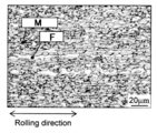
- the metal structure photograph of 1 is shown.
- M represents martensite and F represents ferrite.
- cold rolling with a total rolling rate of 40% is performed to form a cold-rolled sheet of 100 ⁇ m
- SUS304H-TA finish is simulated
- a short-time heat treatment is performed at 500 ° C. and soaking for 0 hour.
- TA steel sheet was prepared.
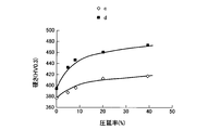
- FIG. 1 shows the surface hardness (c) after temper rolling at 40% and the surface hardness (d) after heat treatment for a short time after temper rolling.
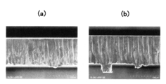
- FIG. 5A steel No. which is the present example is shown.
- FIG. 5B shows a SEM photograph of the laser processed punched portion of the SUS304H-TA material. As shown in FIGS. 5 (a) and 5 (b), this example (steel No. 1) is superior in surface properties.
- the freezing point and the solid-liquid coexistence range were measured by measuring the solidification start temperature and the solidification end temperature by differential heat change.
- the sample size used was 3 mm ⁇ ⁇ 5 mmt, and the cooling rate after melting was 10 ° C./min.
- the measured values of the freezing point and the solid-liquid coexistence temperature of each sample are shown in Table 2.
- FIG. 7 the steel No. which is the present example before and after the repeated printing work. 1 and SSUS photographs near the laser punched portion of SUS304H-TA material are shown. Note that D in FIG. 7 is a drooping (corner drop) portion.
- All of the examples have the same surface hardness as SUS304H-TA and the dross height is reduced by 30% or more.
- the hardness in the vicinity of the laser punched part is lower than the surface hardness of the laser unprocessed part due to thermal effects, but the lower limit of SUS304H-TA material is 170 HV, which is equivalent to the state before rolling.
- the lower limit of each of the examples is 250 HV or higher, and the strength is maintained higher than that of the SUS304H-TA material.
- the present example (steel No. 1) is superior in surface properties to the SUS304H-TA material.
- the SUS304H-TA material is sagging (corner drop) in the vicinity of the punched portion, whereas this example (steel No. 1) No one was confirmed. It is considered that such a person originated from a site where the hardness was remarkably lowered partially due to laser processing.
- the alloy design, double phase treatment, subsequent heat treatment and temper rolling have the same strength as SUS304H-TA material, can reduce the dross height after laser processing, and is durable It can be confirmed that an excellent stainless steel plate can be obtained.
- the present invention is used for a metal mask used when printing a solder paste on a substrate such as a precision machine.
Landscapes
- Chemical & Material Sciences (AREA)
- Engineering & Computer Science (AREA)
- Materials Engineering (AREA)
- Mechanical Engineering (AREA)
- Metallurgy (AREA)
- Organic Chemistry (AREA)
- Heat Treatment Of Sheet Steel (AREA)
- Physics & Mathematics (AREA)
- Thermal Sciences (AREA)
- Crystallography & Structural Chemistry (AREA)
- Printing Plates And Materials Therefor (AREA)
- Laser Beam Processing (AREA)
Abstract
Description
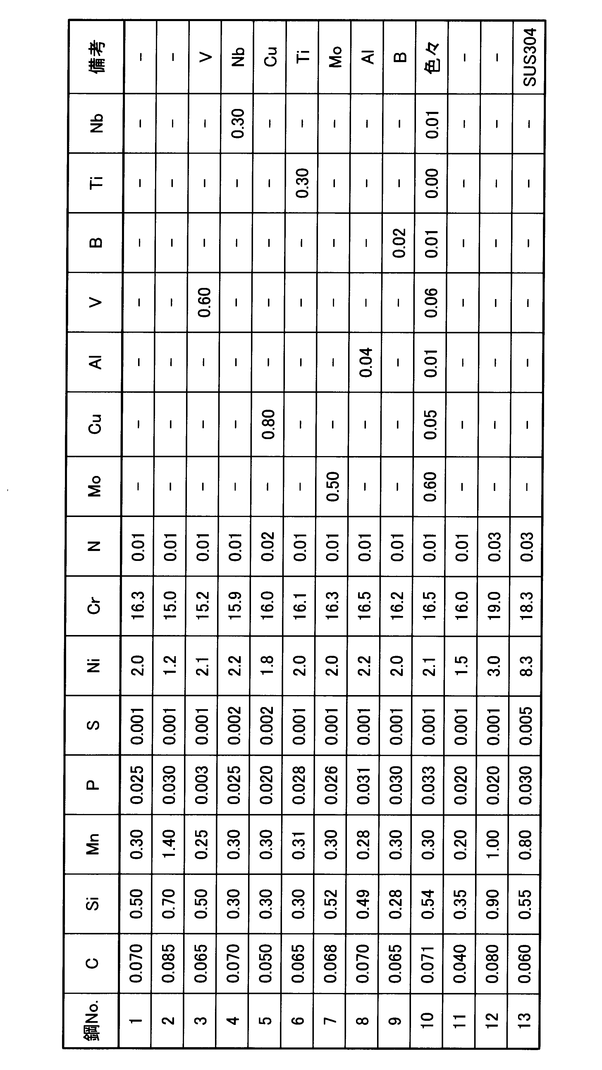
表1に示す各組成のステンレス鋼を30Kg真空溶解炉で溶製してインゴットに鋳造した。得られたインゴットをスラブに分塊し、そのスラブに920℃で熱間圧延を施して、板厚3.0mmの熱延鋼帯とした。
各鋼板について、JISZ-2240の規定に準拠して、鋼板表面の硬さは試験荷重0.3kgでビッカース硬度を測定し、図2に示すレーザー打抜き部近傍の硬さは試験荷重0.01kgでビッカース硬度を測定し、20箇所の平均値を硬さの測定値とした。なお、図2におけるHは硬さ測定箇所を示す。各サンプルの硬度の測定値を表2に示す。表2における硬さ1は表面硬さであり、硬さ2はレーザー打抜き端面から10μm以内の断面硬さである。図3には、本実施例である鋼No.1に40%の調質圧延後短時間熱処理を行ったサンプルNo.3、および、SUS304H-TA材に関する未加工部(鋼板表面)の硬さ(a)と、レーザー打抜き部近傍の硬さ(b)とを示す。図4には、鋼No.1に40%で調質圧延を行った後の表面硬さ(c)と、調質圧延後に短時間熱処理を行った後の表面硬さ(d)とを示す。
各鋼板について、日本車輌製造株式会社製の装置を用いてレーザー加工により、0.5mmΦ、0.2mm×1.3mmの開口部を加工した。加工条件は、出力8W、加工速度400mm/min、ビーム径20μmとした。そして、レーザー加工後のサンプルをSEM観察にて20箇所のドロス高さを測定し、その平均値をドロス高さの測定値とした。各サンプルのドロス高さの測定値を表2に示す。また、図5(a)には、本実施例である鋼No.1のレーザー加工打抜き部のSEM写真を示し、図5(b)にはSUS304H-TA材のレーザー加工打抜き部のSEM写真を示す。これら図5(a)および図5(b)に示すように本実施例(鋼No.1)の方が表面性状に優れている。
示差熱変化により、凝固開始温度および凝固終了温度を測定することで、凝固点および固液共存範囲を測定した。用いたサンプル寸法は、3mmΦ×5mmt、溶融後の冷却速度は10℃/minで測定を実施した。各サンプルの凝固点および固液共存温度の測定値を表2に示す。
印刷作業は、ヤマハ発動機株式会社製のソルダペースト印刷機およびメタルスキージを用いてスキージ角度60度、印刷速度100mm/sec、印刷圧力50N/cm2ではんだペースト印刷作業を行った。また、2万回印刷を実施した後、図6に示すレーザー打抜き部近傍のだれの有無をSEM観察にて確認した。図6におけるDはだれ量の測定箇所である。なお、だれの程度については、だれ発生箇所の断面観察を行い、角落ちした部分の面積を算出して求めた。各サンプルのだれに関する測定値を表2に示す。また、図7には、繰り返し印刷作業前後の本実施例である鋼No.1およびSUS304H-TA材のレーザー打抜き部近傍のSEM写真を示す。なお、図7におけるDはだれ(角落ち)部分である。

Claims (5)
- 質量%で、C:0.15%以下、Si:2.0%以下、Mn:4.0%以下、P:0.04%以下、S:0.03%以下、Ni:4.0%以下、Cr:10~20%、N:0.12%以下を含有し、残部がFeおよび不可避的不純物からなり、
[420(%C)+470(%N)+23(%Ni)+7(%Mn)-11.5(%Cr)-11.5(%Si)+189]で示されるγmax値が70~90で、金属組織がフェライト相およびマルテンサイト相の二相組織であり、
[1519-(1.3+109.07(%C)+13(%C)2+16.38(%Si)+7.02(%Mn)+6.63(%Ni)+1.95(%Cr)+39(%P)+48.1(%S))]で示される凝固終了温度が1450℃以上であり、
[6.752+(0.393+32.97(%C)+3.93(%C)2+4.95(%Si)+2.12(%Mn)+2.00(%Ni)+0.59(%Cr)+11.8(%P)+14.54(%S))]で示される溶融状態から凝固する過程での固液共存範囲が30℃以内である
ことを特徴とするメタルマスク用ステンレス鋼板。 - V、Nb、Cu、Ti、Al、BおよびMoの少なくとも1つを合計1.0質量%以下で含有し、
[420(%C)+470(%N)+23(%Ni)+7(%Mn)-11.5(%Cr)-11.5(%Si)-12(%Mo)-23(%V)-47(%Nb)-49(%Ti)-52(%Al)+189]で示されるγmax値が70~90で、金属組織がフェライト相およびマルテンサイト相の二相組織であり、
[1519-(1.3+109.07(%C)+13(%C)2+16.38(%Si)+7.02(%Mn)+5.98(%Cu)+6.63(%Ni)+1.95(%Cr)+4.29(%Mo)+39(%P)+48.1(%S)+12.35(%Nb))]で示される凝固終了温度が1450℃以上であり、
[6.752+(0.393+32.97(%C)+3.93(%C)2+4.95(%Si)+2.12(%Mn)+1.81(%Cu)+2.00(%Ni)+0.59(%Cr)+1.30(%Mo)+11.8(%P)+14.54(%S)+3.73(%Nb))]で示される溶融状態から凝固する過程での固液共存範囲が30℃以内である
ことを特徴とする請求項1記載のメタルマスク用ステンレス鋼板。 - 冷間圧延後に300~550℃で短時間の熱処理が施された
ことを特徴とする請求項1または2記載のメタルマスク用ステンレス鋼板。 - 冷間圧延後に、50%以下の調質圧延が施され、その後300~550℃で短時間の熱処理が施された
ことを特徴とする請求項1または2記載のメタルマスク用ステンレス鋼板。 - レーザー加工用として使用され、
レーザー打抜き端面から10μm以内の断面硬さが250HV以上である
ことを特徴とする請求項1ないし4のいずれか一記載のメタルマスク用ステンレス鋼板。
Priority Applications (3)
| Application Number | Priority Date | Filing Date | Title |
|---|---|---|---|
| JP2012516409A JP5426764B2 (ja) | 2011-03-31 | 2012-03-30 | メタルマスク用ステンレス鋼板およびメタルマスク |
| KR1020137025561A KR20130125832A (ko) | 2011-03-31 | 2012-03-30 | 메탈 마스크용 스테인리스 강판 |
| CN201280015780.6A CN103476958B (zh) | 2011-03-31 | 2012-03-30 | 金属掩膜用不锈钢板 |
Applications Claiming Priority (2)
| Application Number | Priority Date | Filing Date | Title |
|---|---|---|---|
| JP2011078322 | 2011-03-31 | ||
| JP2011-078322 | 2011-03-31 |
Publications (1)
| Publication Number | Publication Date |
|---|---|
| WO2012133833A1 true WO2012133833A1 (ja) | 2012-10-04 |
Family
ID=46931527
Family Applications (1)
| Application Number | Title | Priority Date | Filing Date |
|---|---|---|---|
| PCT/JP2012/058700 Ceased WO2012133833A1 (ja) | 2011-03-31 | 2012-03-30 | メタルマスク用ステンレス鋼板 |
Country Status (4)
| Country | Link |
|---|---|
| JP (2) | JP5426764B2 (ja) |
| KR (1) | KR20130125832A (ja) |
| CN (1) | CN103476958B (ja) |
| WO (1) | WO2012133833A1 (ja) |
Cited By (3)
| Publication number | Priority date | Publication date | Assignee | Title |
|---|---|---|---|---|
| CN102899590A (zh) * | 2012-10-13 | 2013-01-30 | 山东理工大学 | 长寿命水力碎浆机叶轮及其制造方法 |
| KR101412938B1 (ko) | 2012-12-24 | 2014-06-26 | 주식회사 포스코 | 가공성이 우수한 스테인리스강 및 이의 제조방법 |
| JP2017160491A (ja) * | 2016-03-09 | 2017-09-14 | 日新製鋼株式会社 | 加工性に優れた高強度ステンレス鋼材とその製造方法 |
Citations (7)
| Publication number | Priority date | Publication date | Assignee | Title |
|---|---|---|---|---|
| JP2000319765A (ja) * | 1999-05-07 | 2000-11-21 | Sumitomo Metal Ind Ltd | シャドウマスク用ステンレス鋼板 |
| JP2001234236A (ja) * | 2000-02-28 | 2001-08-28 | Nisshin Steel Co Ltd | 強度・延性・靱性に優れたマルテンサイト系ステンレス鋼材の製造方法 |
| JP2002105601A (ja) * | 2000-09-27 | 2002-04-10 | Nisshin Steel Co Ltd | 高強度複相ステンレス鋼及びその製造方法 |
| JP2003041350A (ja) * | 2001-08-01 | 2003-02-13 | Nisshin Steel Co Ltd | フラッパーバルブ用マルテンサイト系ステンレス鋼板およびその製造方法 |
| JP2004131743A (ja) * | 2002-08-09 | 2004-04-30 | Nisshin Steel Co Ltd | エッチング加工用ステンレス鋼板 |
| JP2006249514A (ja) * | 2005-03-11 | 2006-09-21 | Jfe Steel Kk | 高強度かつ加工性に優れたCr含有合金熱延鋼板およびその製造方法 |
| WO2009099035A1 (ja) * | 2008-02-07 | 2009-08-13 | Nisshin Steel Co., Ltd. | 高強度ステンレス鋼材及びその製造方法 |
Family Cites Families (1)
| Publication number | Priority date | Publication date | Assignee | Title |
|---|---|---|---|---|
| WO2000068449A1 (fr) * | 1999-05-07 | 2000-11-16 | Matsushita Electric Industrial Co., Ltd. | Tole en acier inoxydable pour masque perfore, procede de fabrication associe et masque perfore |
-
2012
- 2012-03-30 CN CN201280015780.6A patent/CN103476958B/zh active Active
- 2012-03-30 WO PCT/JP2012/058700 patent/WO2012133833A1/ja not_active Ceased
- 2012-03-30 JP JP2012516409A patent/JP5426764B2/ja active Active
- 2012-03-30 KR KR1020137025561A patent/KR20130125832A/ko not_active Ceased
-
2013
- 2013-11-28 JP JP2013245727A patent/JP5697218B2/ja active Active
Patent Citations (7)
| Publication number | Priority date | Publication date | Assignee | Title |
|---|---|---|---|---|
| JP2000319765A (ja) * | 1999-05-07 | 2000-11-21 | Sumitomo Metal Ind Ltd | シャドウマスク用ステンレス鋼板 |
| JP2001234236A (ja) * | 2000-02-28 | 2001-08-28 | Nisshin Steel Co Ltd | 強度・延性・靱性に優れたマルテンサイト系ステンレス鋼材の製造方法 |
| JP2002105601A (ja) * | 2000-09-27 | 2002-04-10 | Nisshin Steel Co Ltd | 高強度複相ステンレス鋼及びその製造方法 |
| JP2003041350A (ja) * | 2001-08-01 | 2003-02-13 | Nisshin Steel Co Ltd | フラッパーバルブ用マルテンサイト系ステンレス鋼板およびその製造方法 |
| JP2004131743A (ja) * | 2002-08-09 | 2004-04-30 | Nisshin Steel Co Ltd | エッチング加工用ステンレス鋼板 |
| JP2006249514A (ja) * | 2005-03-11 | 2006-09-21 | Jfe Steel Kk | 高強度かつ加工性に優れたCr含有合金熱延鋼板およびその製造方法 |
| WO2009099035A1 (ja) * | 2008-02-07 | 2009-08-13 | Nisshin Steel Co., Ltd. | 高強度ステンレス鋼材及びその製造方法 |
Cited By (3)
| Publication number | Priority date | Publication date | Assignee | Title |
|---|---|---|---|---|
| CN102899590A (zh) * | 2012-10-13 | 2013-01-30 | 山东理工大学 | 长寿命水力碎浆机叶轮及其制造方法 |
| KR101412938B1 (ko) | 2012-12-24 | 2014-06-26 | 주식회사 포스코 | 가공성이 우수한 스테인리스강 및 이의 제조방법 |
| JP2017160491A (ja) * | 2016-03-09 | 2017-09-14 | 日新製鋼株式会社 | 加工性に優れた高強度ステンレス鋼材とその製造方法 |
Also Published As
| Publication number | Publication date |
|---|---|
| JP2014080688A (ja) | 2014-05-08 |
| JP5426764B2 (ja) | 2014-02-26 |
| JPWO2012133833A1 (ja) | 2014-07-28 |
| KR20130125832A (ko) | 2013-11-19 |
| CN103476958A (zh) | 2013-12-25 |
| JP5697218B2 (ja) | 2015-04-08 |
| CN103476958B (zh) | 2015-10-14 |
Similar Documents
| Publication | Publication Date | Title |
|---|---|---|
| JP7642785B2 (ja) | 耐食性に優れるマルテンサイト系ステンレス鋼板及びその製造方法、並びにマルテンサイト系ステンレス刃物製品 | |
| KR100765661B1 (ko) | 저탄소 마르텐사이트계 스테인레스 강판 및 이의 제조방법 | |
| CN104471095B (zh) | 马氏体系不锈钢及其制造方法 | |
| CN107075632B (zh) | 奥氏体系不锈钢板和其制造方法 | |
| JP6417252B2 (ja) | ブレーキディスク用マルテンサイト系ステンレス鋼とその製造方法 | |
| JP7568473B2 (ja) | オーステナイト系ステンレス鋼帯または熱延オーステナイト系ステンレス鋼板およびオーステナイト系ステンレス鋼の製造方法 | |
| JP5696225B2 (ja) | 高耐食マルテンサイト系ステンレス鋼およびその製造方法 | |
| JP3691341B2 (ja) | 精密打抜き性に優れたオーステナイト系ステンレス鋼板 | |
| JP6635890B2 (ja) | 製造性と耐食性に優れた刃物用マルテンサイト系ステンレス鋼板 | |
| JP5697218B2 (ja) | メタルマスク | |
| JP4272394B2 (ja) | 精密打抜き加工性に優れるフェライト系ステンレス鋼 | |
| JP4830239B2 (ja) | 打ち抜き性に優れた低炭素マルテンサイト系ステンレス熱延鋼板の製造方法 | |
| KR101940427B1 (ko) | 페라이트계 스테인리스 강판 | |
| JP6359241B2 (ja) | 鏡面性に優れた耐食性プラスチック成形金型用鋼 | |
| TWI737475B (zh) | 麻田散鐵系不鏽鋼板及麻田散鐵系不鏽鋼構件 | |
| JP2020152992A (ja) | ステンレス鋼板、ダイクエンチ部材、およびダイクエンチ部材の製造方法 | |
| JP4073844B2 (ja) | オートバイブレーキディスク用ステンレス鋼 | |
| JPH07268455A (ja) | 熱間圧延での微小割れを防止するCr−Ni系ステンレス合金の製造方法 | |
| TWI747722B (zh) | 麻田散鐵系不鏽鋼板及麻田散鐵系不鏽鋼構件 | |
| WO2016043050A1 (ja) | ブレーキディスク用マルテンサイト系ステンレス鋼とその製造方法 | |
| JP3727646B2 (ja) | 精密打抜き性に優れたオーステナイト系ステンレス鋼板の製造方法 | |
| JP2003113450A (ja) | 精密打抜き性に優れたオーステナイト系ステンレス鋼 | |
| JP3331163B2 (ja) | 表面光沢むらのないオーステナイト系ステンレス鋼板の製造方法 | |
| JP4496659B2 (ja) | 打ち抜き加工性に優れたマルテンサイト系ステンレス鋼 | |
| JP2000079405A (ja) | 表面性状の良好なオーステナイト系ステンレス薄鋼板の製造方法 |
Legal Events
| Date | Code | Title | Description |
|---|---|---|---|
| ENP | Entry into the national phase |
Ref document number: 2012516409 Country of ref document: JP Kind code of ref document: A |
|
| 121 | Ep: the epo has been informed by wipo that ep was designated in this application |
Ref document number: 12762768 Country of ref document: EP Kind code of ref document: A1 |
|
| ENP | Entry into the national phase |
Ref document number: 20137025561 Country of ref document: KR Kind code of ref document: A |
|
| NENP | Non-entry into the national phase |
Ref country code: DE |
|
| WWE | Wipo information: entry into national phase |
Ref document number: 1301005281 Country of ref document: TH |
|
| 122 | Ep: pct application non-entry in european phase |
Ref document number: 12762768 Country of ref document: EP Kind code of ref document: A1 |