WO2012133552A1 - レンズユニット、及び撮像ユニット - Google Patents
レンズユニット、及び撮像ユニット Download PDFInfo
- Publication number
- WO2012133552A1 WO2012133552A1 PCT/JP2012/058183 JP2012058183W WO2012133552A1 WO 2012133552 A1 WO2012133552 A1 WO 2012133552A1 JP 2012058183 W JP2012058183 W JP 2012058183W WO 2012133552 A1 WO2012133552 A1 WO 2012133552A1
- Authority
- WO
- WIPO (PCT)
- Prior art keywords
- resin
- lens
- unit
- optical system
- imaging unit
- Prior art date
- Legal status (The legal status is an assumption and is not a legal conclusion. Google has not performed a legal analysis and makes no representation as to the accuracy of the status listed.)
- Ceased
Links
Images



Classifications
-
- G—PHYSICS
- G02—OPTICS
- G02B—OPTICAL ELEMENTS, SYSTEMS OR APPARATUS
- G02B7/00—Mountings, adjusting means, or light-tight connections, for optical elements
- G02B7/02—Mountings, adjusting means, or light-tight connections, for optical elements for lenses
- G02B7/021—Mountings, adjusting means, or light-tight connections, for optical elements for lenses for more than one lens
-
- G—PHYSICS
- G02—OPTICS
- G02B—OPTICAL ELEMENTS, SYSTEMS OR APPARATUS
- G02B13/00—Optical objectives specially designed for the purposes specified below
- G02B13/001—Miniaturised objectives for electronic devices, e.g. portable telephones, webcams, PDAs, small digital cameras
Definitions
- the present invention relates to a lens unit and an imaging unit.
- An imaging unit used for an in-vehicle camera generally includes an imaging element such as a CCD (Charge Coupled Device) image sensor or a CMOS (Complementary Metal-Oxide Semiconductor) image sensor, and a lens unit that forms an image on a light receiving surface of the imaging element.
- an imaging element such as a CCD (Charge Coupled Device) image sensor or a CMOS (Complementary Metal-Oxide Semiconductor) image sensor
- CMOS Complementary Metal-Oxide Semiconductor
- the lens unit includes a plurality of lenses and a lens barrel that houses these lenses.
- Patent Document 1 and Patent Document 2 describe an imaging unit including such a lens unit.
- a resin excellent in heat resistance, chemical resistance, and weather resistance is used as a material of the lens barrel.
- a polyamide resin (PA) and a prephthalamide resin (PPA) are often used.
- these resins have a large dimensional change due to the use environment, and particularly a large dimensional change due to humidity.
- a lens unit and an imaging unit including a lens barrel made of these resins are used in a hot and humid environment, a dimensional change occurs in the lens barrel, and a gap is generated between the lens and the lens barrel. is there.
- the lens barrel and axial displacement may occur in the lens barrel, and the optical performance of the lens unit and the imaging unit may deteriorate.
- the present invention has been made in view of the above circumstances, and it is an object of the present invention to provide a lens unit and an imaging unit that can suppress deterioration of optical performance while ensuring resistance to heat from the outside.
- the cylindrical portion is formed by multicolor molding using a first resin and a second resin that forms a portion including at least a lens fitting portion into which the lens is fitted, and the second resin
- the lens unit is a resin whose dimensional change according to humidity is smaller than that of the first resin.
- a sensor unit including an optical system including at least one lens, an image sensor that forms an image of the light of the optical system, a sensor substrate on which the image sensor is fixed, and the optical system for the sensor substrate.
- a lens holding member for fixing the position wherein the lens holding member has a first resin forming a first portion exposed to the outside of the lens holding member, and a lens fitting into which the lens is fitted.
- a second resin forming a second part having at least one of a joint portion and an attachment portion for attaching the lens holding member to the sensor substrate, and the second resin.
- the imaging unit whose resin is resin with a small dimensional change according to humidity compared with the said 1st resin.
- the present invention it is possible to provide a lens unit and an imaging unit that can suppress deterioration of optical performance while ensuring resistance to heat from the outside.
- FIG. 1 It is a figure which shows an example of a structure of the lens unit for describing embodiment of this invention. It is a figure which shows the imaging unit provided with the lens unit of FIG. It is sectional drawing of the lens barrel of the lens unit of FIG. It is a figure which shows the modification of a structure of the imaging unit of FIG. It is a figure which shows the other modification of a structure of the imaging unit of FIG.
- FIG. 1 is a diagram illustrating an example of a configuration of a lens unit.
- the lens unit 10 includes an optical system 4 that includes a plurality of lenses, and a lens barrel 1 that houses the optical system 4.
- the optical system 4 includes a first lens 11, a second lens 21, a third lens 31, and a fourth lens 41 that are arranged in order from the incident side (subject side). Yes.
- the configuration of the optical system 4 is not limited to the illustrated example.
- the number of lenses may be 3, or 5 or more.
- the lens barrel 1 includes a cylindrical tube portion 1a into which each lens is fitted, and a bottom portion 1b provided at one end portion in the axial direction of the tube portion 1a. Further, the end of the tube portion 1a of the barrel 1 opposite to the bottom portion 1b in the axial direction is open.
- the lens barrel 1 is provided with a stepped portion 7 on the inner peripheral surface of the tube portion 1a.
- the step portion 7 is provided in an annular shape around the central axis of the cylindrical portion 1a.
- the optical system 4 is disposed in the tube portion 1a in a state where the optical axis thereof coincides with the central axis of the tube portion 1a of the lens barrel 1.
- An opening 3 is provided at the center of the bottom 1b through which the optical axis of the optical system 4 passes. The light transmitted through the optical system 4 passes through the opening 3 and enters an image sensor of a sensor unit (see FIG. 2) described later.
- the first lens 11, the second lens 21, the third lens 31, and the fourth lens 41 are arranged in this order from the end opposite to the bottom 1b of the lens barrel 1 in this order.
- the first lens 11 is composed of a lens portion 12 having optical surfaces on the front and back sides and an edge portion 13 extending around the lens portion 12.
- the second lens 21 includes a lens part 22 having optical surfaces on the front and back sides and an edge part 23 extending around the lens part 22.
- the third lens 31 includes a lens part 32 having optical surfaces on the front and back sides and an edge part 33 that spreads around the lens part 32 in a bowl shape.
- the fourth lens 41 includes a lens part 42 having optical surfaces on the front and back sides, and an edge part 43 that spreads around the lens part 42 in a bowl shape.
- the first lens 11, the second lens 21, the third lens 31, and the fourth lens 41 are respectively fitted on the inner peripheral surface of the lens barrel 1.
- the edge portions 13, 23, 33, and 43 of the first lens 11, the second lens 21, the third lens 31, and the fourth lens 41 are in contact with the inner peripheral surface of the lens barrel 1.
- the edge portion 13 of the first lens 11 is held by the tube portion 1a from the subject side by caulking the tip portion of the tube portion 1a.
- the diameter of the first lens 11 is larger than the diameter of the second lens 21.
- the diameter of the second lens 21 is larger than the diameter of the third lens 31.
- the diameter of the third lens 31 is larger than the diameter of the fourth lens 41.
- the first lens 11, the second lens 21, the third lens 31, and the fourth lens 41 are collectively referred to simply as a lens.
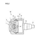
- FIG. 2 is a diagram illustrating an example of a configuration of an imaging unit including the lens unit of FIG.
- the imaging unit 100 includes the lens unit 10 of FIG. 1, a sensor unit 101, an outer cover part 102, a holder part 103, a connection part 108, and a wiring 110.
- the sensor unit 101 includes a main body cover 105, an image sensor 106 built in the main body cover 105, and a sensor substrate 104 to which the image sensor 106 is attached.
- the image sensor 106 converts an image formed by the optical system 4 into an electrical signal.
- the image sensor 106 is, for example, a CCD image sensor or a CMOS image sensor.
- the sensor substrate 104 is a plate-like member that supports the image sensor 106 so that the imaging surface of the image sensor 106 is perpendicular to the optical axis of the optical system 4.
- the holder portion 103 is a frame-like member that holds the lens barrel 1 of the lens unit 10. In addition, the holder portion 103 is fixed to the sensor substrate 104. Although not shown, the holder portion 103 has an inner peripheral surface that is screw-fitted with the outer peripheral surface of the cylindrical portion 1 a of the lens barrel 1, and positions the optical system 4 in the optical axis direction with respect to the imaging element 106.
- the outer cover portion 102 covers the periphery of the lens barrel 1 and the holder portion 103, and holds the outer periphery of the lens barrel 1 of the lens unit 10 on the subject side. Further, the outer cover portion 102 is fixed to the main body cover 105.
- connection unit 108 connects the wiring extending from the sensor substrate 104 in the main body cover 105 to the wiring 110 extending outward from the main body cover 105.
- the lens barrel 1 is formed by two-color molding.
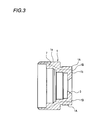
- FIG. 3 is a cross-sectional view of the lens barrel 1 of the lens unit 10.
- disconnected in parallel with respect to the central axis of the cylinder part 1a of the lens barrel 1 is shown.
- a portion 1A including an outer surface is formed of a first resin.
- Part 1B including the inner surface is formed of the second resin.
- the resin having different performance is used for the first resin and the second resin.
- a resin having excellent heat resistance, chemical resistance, and weather resistance is used as the first resin.
- resins include polyamide resin (PA), polyphthalamide resin (PPA), polycarbonate resin (PC), polyphenylene sulfide resin (PPS), polybutylene terephthalate resin (PBT), and polyether sulfone resin (PES).
- PPE polyphenylene ether resin
- PE polyethylene resin
- PAR polyarylate resin
- LCP liquid crystal polymer resin
- PEEK polyether ether ketone resin
- PI polyimide resin
- PAI polyamideimide resin
- the second resin a resin whose dimensional change due to humidity is smaller than that of the first resin is used.
- a resin is a resin whose dimensional change due to humidity is smaller than that of the first resin, such as PA, PPA, PC, PPS, PBT, PES, PPE, PE, PAR, LCP, PEEK, PI, PAI, and the like.
- the first resin and the second resin may be a combination of different types of resins, or may be resins of the same type and different grades.
- a portion 1B including a lens fitting portion that is provided on the inner surface of the barrel portion 1a of the lens barrel 1 and into which each lens of the optical system 4 is fitted is formed of the second resin.
- the second resin is less deformed depending on the humidity than the first resin that forms the outside of the cylindrical portion 1a. Therefore, the lens barrel 1 is less likely to undergo a dimensional change on the side that holds each lens in the lens barrel 1, and can prevent a gap from being generated between the lens and the lens barrel 1. Therefore, the imaging unit 100 including the lens unit 10 and the lens unit 10 can suppress deterioration in optical performance.
- the portion 1B including the entire inner surface of the tube portion 1a is formed of the second resin, but is not limited thereto.
- the portion 1B including at least the lens fitting portion in the cylindrical portion 1a with the second resin, it is possible to suppress a gap from being generated between the lens and the lens barrel 1 due to a dimensional change of the cylindrical portion 1a due to humidity.
- FIG. 4 shows a modification of the configuration of the imaging unit.
- a holder portion for holding the lens barrel 1 of the lens unit 10 and an outer cover portion covering the outer periphery of the lens barrel 1 of the lens unit 10 are integrally formed by two-color molding.
- a portion integrally formed by the two-color molding functions as the lens holding member 141.
- the lens holding member 141 has a substantially cylindrical shape centered on the optical axis of the optical system 4. As shown by a dotted line in FIG. 4, the lens holding member 141 is arranged on the inner side of the outer part 141 ⁇ / b> A as an example of an outer cover part that is an exposed part of the lens holding member 141 and on the inner side of the outer part 141 ⁇ / b> A. It is divided into an inner portion 141B as an example of the holder portion.
- the outer portion 141A having the outer diameter of the lens holding member 141 is formed of the first resin, and the inner portion 141B on the inner diameter side is formed of the second resin.
- the lens holding member 141 is formed by two-color molding of the first resin and the second resin.
- the lens holding member 141 holds the lens unit 10 including the optical system 4 and fixes the position of the optical system 4 with respect to the sensor substrate 104.
- an outer portion 141A that is a portion exposed to the outside in the lens holding member 141 is formed of the first resin.
- the first resin a resin having excellent heat resistance, chemical resistance, and weather resistance is used. Examples of such a resin include PA and PPA.
- the inner part 141B other than the outer part 141A formed of the first resin is formed of the second resin.
- the second resin a resin whose dimensional change due to humidity is smaller than that of the first resin is used as described above.
- the inner portion 141B includes an attachment portion 143 for fixing the lens unit 10 and attaching the lens holding member 141 to the sensor substrate 104.
- the mounting portion 143 is joined to the periphery of the surface on which the image sensor 106 of the sensor substrate 104 is mounted.
- the attachment portion 143 has a side wall that is substantially perpendicular to the surface of the sensor substrate 104, and is formed so as to surround the imaging element 106 by the side wall.
- the attachment portion 143 defines the distance between the optical system 4 held by the lens holding member 141 and the image sensor 106 of the sensor substrate 104.
- the inner portion 141B including the attachment portion 143 in the lens holding member 141 is formed of the second resin, the dimensional deformation due to humidity is less than that of the first resin forming the outer portion 141A of the lens holding member 141. Hard to occur.
- the outer portion 141A constituting the outer side is superior in heat resistance, chemical resistance, and weather resistance as compared to the inner portion 141B constituting the inner side.
- the imaging unit 100 including the lens holding member 141 has the outer portion 141A to ensure heat resistance, chemical resistance, and weather resistance, and to the mounting portion 143 using a resin that hardly causes dimensional deformation due to humidity. Reduces dimensional deformation due to humidity. For this reason, it can suppress that the space
- FIG. 5 shows another modification of the configuration of the imaging unit.
- a holder part that also functions as a lens barrel that houses the optical system 4 and an outer cover part that covers the outer periphery of the holder part are integrally formed by two-color molding.
- a portion integrally formed by the two-color molding functions as the lens holding member 51.
- an outer portion 51A as an outer cover portion which is a portion exposed to the outside in the lens holding member 51 is formed of the first resin.
- the first resin a resin having excellent heat resistance, chemical resistance, and weather resistance is used. Examples of such a resin include PA and PPA.
- the inner part 51B as the holder part other than the outer part 51A formed of the first resin is formed of the second resin.
- the second resin a resin whose dimensional change due to humidity is smaller than that of the first resin is used as described above.
- the inner portion 51 ⁇ / b> B formed of the second resin includes a lens fitting portion 151 into which each lens of the optical system 4 is fitted, and an attachment portion 153 for attaching the lens holding member 51 to the sensor substrate 104. .
- the attachment portion 153 is joined to the periphery of the surface on which the image sensor 106 of the sensor substrate 104 is mounted, similarly to the attachment portion 143 described above.
- the attachment portion 153 has a side wall that is substantially perpendicular to the surface of the sensor substrate 104, and is formed so as to surround the imaging element 106 by the side wall.
- the attachment portion 153 defines the distance between the optical system 4 held by the lens holding member 51 and the image sensor 106 of the sensor substrate 104.
- the inner portion 51B of the lens holding member 51 has a lens fitting portion 151 into which the edge portion of each lens is fitted integrally with the mounting portion 153.
- This lens fitting portion 151 is also formed of the second resin.
- the outer portion 51A constituting the outside of the lens holding member 51 is superior in heat resistance, chemical resistance, and weather resistance compared to the inner portion 51B constituting the inside.
- the lens fitting portion 151 by forming the lens fitting portion 151 with the second resin, it is possible to suppress a gap from being generated between the lens fitting portion 151 of the lens holding member 51 and the lens.
- the imaging unit 100 including the lens holding member 51 it is possible to suppress deterioration of optical performance.
- the lens fitting portion 151 and the attachment portion 153 of the lens holding member 51 are both formed of the second resin, but the present invention is not limited to this.
- the present invention is not limited to this.
- by forming at least one of the lens fitting portion 151 and the attachment portion 153 with the second resin it is possible to obtain an effect of suppressing dimensional change due to humidity and suppressing deterioration of optical performance.
- lens unit and imaging unit are examples formed by two-color molding, but are not limited thereto.
- the lens unit and the imaging unit may be formed by multicolor molding using three or more different resins.
- a lens unit including an optical system including at least one lens and a lens barrel that houses the optical system, and the lens barrel has a cylindrical tube portion into which the lens is fitted.
- the cylindrical portion is formed by multicolor molding using a first resin and a second resin that forms a portion including at least a lens fitting portion into which the lens is fitted, and the second resin
- the lens unit is a resin whose dimensional change according to humidity is smaller than that of the first resin.
- the first resin is polyamide resin (PA), polyphthalamide resin (PPA), polycarbonate resin (PC), polyphenylene sulfide resin (PPS), poly Butylene terephthalate resin (PBT), polyether sulfone resin (PES), polyphenylene ether resin (PPE), polyethylene resin (PE), polyarylate resin (PAR), liquid crystal polymer resin (LCP), polyether ether ketone resin (PEEK) ), A polyimide resin (PI), or a polyamide-imide resin (PAI), wherein the second resin is the same or different kind of resin as the first resin, A lens unit that is a resin whose dimensional change due to humidity is smaller than that of resin.
- PA polyamide resin
- PPA polyphthalamide resin
- PC polycarbonate resin
- PPS polyphenylene sulfide resin
- PBT poly Butylene terephthalate resin
- PES polyether sulfone resin
- PPE polyphenylene ether resin
- PE polyethylene
- the lens unit according to (1) or (2) an image sensor that forms an image of the light of the optical system, a sensor unit that includes a sensor substrate on which the image sensor is fixed, and a sensor unit that is fixed to the sensor substrate.
- An imaging unit comprising: a holder portion that holds the lens barrel; and an outer cover portion that covers the periphery of the lens barrel and the holder portion.
- a sensor unit including an optical system including at least one lens, an image sensor that forms an image of light of the optical system, a sensor substrate on which the image sensor is fixed, and the optical system for the sensor substrate.
- a lens holding member for fixing the position wherein the lens holding member has a first resin forming a first portion exposed to the outside of the lens holding member, and a lens fitting into which the lens is fitted.
- a second resin forming a second part having at least one of a joint portion and an attachment portion for attaching the lens holding member to the sensor substrate, and the second resin.
- the imaging unit whose resin is resin with a small dimensional change according to humidity compared with the said 1st resin.
- the imaging unit according to (4) including a lens unit including a lens barrel that accommodates the optical system, wherein the lens holding member includes the mounting portion and fixes the lens unit.
- the lens holding member covers a holder portion as a second part having the attachment portion and the lens fitting portion, and a periphery of the optical system.
- the imaging unit is a polyamide resin (PA), a polyphthalamide resin (PPA), or a polycarbonate resin (PC).
- PA polyamide resin
- PPA polyphthalamide resin
- PC polycarbonate resin
- PPS Polyphenylene sulfide resin
- PBT polybutylene terephthalate resin
- PES polyether sulfone resin
- PPE polyphenylene ether resin
- PE polyethylene resin
- PAR polyarylate resin
- LCP liquid crystal polymer resin
- PEEK Polyetheretherketone resin
- PI polyimide resin
- PAI polyamideimide resin
- An imaging unit that is a resin and has a smaller dimensional change due to humidity than the first resin.
- the lens unit and the imaging unit described above are useful when used for cameras that require resistance to environmental temperature changes and humidity. For example, it is useful for a vehicle-mounted camera provided for back monitoring or front monitoring. Further, the lens unit and the imaging unit described above are not limited to a vehicle-mounted camera, and are useful for a camera mounted on a terminal such as a mobile phone.
Landscapes
- Physics & Mathematics (AREA)
- General Physics & Mathematics (AREA)
- Optics & Photonics (AREA)
- Lens Barrels (AREA)
- Camera Bodies And Camera Details Or Accessories (AREA)
- Studio Devices (AREA)
Abstract
少なくとも1つのレンズを含む光学系と、光学系を収容する鏡筒と、を備えるレンズユニット及びそのレンズユニットを備える撮像ユニットであって、鏡筒はレンズが嵌合される筒状の筒部を有し、筒部は、第1の樹脂と、レンズが嵌合されるレンズ嵌合部を少なくとも含む部位を形成する第2の樹脂とを用いて多色成形により形成され、第2の樹脂が、第1の樹脂と比べて湿度に応じた寸法変化が小さい樹脂である。
Description
本発明は、レンズユニット、及び撮像ユニットに関する。
現在、バックモニタや前方監視に用いられる車載用カメラが普及している。
車載用カメラに用いられる撮像ユニットは、一般に、CCD(Charge Coupled Device)イメージセンサやCMOS(Complementary metal-Oxide Semiconductor)イメージセンサなどの撮像素子と、撮像素子の受光面に結像するレンズユニットとを備える。
レンズユニットは、複数のレンズと、これらのレンズを収容する鏡筒とを備える。例えば、特許文献1や特許文献2は、このようなレンズユニットを備えた撮像ユニットを記載している。
ところで、撮像ユニットに用いられるレンズユニットにおいて、鏡筒の材質としては、耐熱性、耐薬品性、及び耐候性に優れた樹脂が用いられる。例えば、ポリアミド樹脂(PA)やプリフタルアミド樹脂(PPA)が多く用いられている。一方で、これらの樹脂は、使用環境による寸法変化が大きく、特に湿度による寸法変化が大きい。このため、これらの樹脂で形成された鏡筒を備えるレンズユニット及び撮像ユニットを高温多湿の環境下で使用すると、鏡筒に寸法変化が生じ、レンズと鏡筒との間に隙間が生じることがある。すると、鏡筒においてレンズの倒れや軸ズレが生じ、レンズユニットや撮像ユニットの光学性能が劣化することがある。
本発明は、上記事情を鑑みてなされたものであり、外部からの熱等に対する耐性を確保しつつ、光学性能の劣化を抑えることができるレンズユニット、及び撮像ユニットを提供することにある。
(1) 少なくとも1つのレンズを含む光学系と、上記光学系を収容する鏡筒と、を備えるレンズユニットであって、上記鏡筒は上記レンズが嵌合される筒状の筒部を有し、上記筒部は、第1の樹脂と、上記レンズが嵌合されるレンズ嵌合部を少なくとも含む部位を形成する第2の樹脂とを用いて多色成形により形成され、上記第2の樹脂が、上記第1の樹脂と比べて湿度に応じた寸法変化が小さい樹脂であるレンズユニット。
(2) 少なくとも1つのレンズを含む光学系と、上記光学系の光を結像する撮像素子と、撮像素子が固定されたセンサ基板とを内蔵するセンサユニットと、上記センサ基板に対する上記光学系の位置を固定するレンズ保持部材と、を備え、上記レンズ保持部材は、レンズ保持部材における外部に露呈している第1の部位を形成する第1の樹脂と、上記レンズが嵌合されるレンズ嵌合部及び上記レンズ保持部材を上記センサ基板に取り付けるための取付け部とのうち少なくとも一方を有する第2の部位を形成する第2の樹脂とを用いて多色成形により形成され、上記第2の樹脂が、上記第1の樹脂と比べて湿度に応じた寸法変化が小さい樹脂である撮像ユニット。
(2) 少なくとも1つのレンズを含む光学系と、上記光学系の光を結像する撮像素子と、撮像素子が固定されたセンサ基板とを内蔵するセンサユニットと、上記センサ基板に対する上記光学系の位置を固定するレンズ保持部材と、を備え、上記レンズ保持部材は、レンズ保持部材における外部に露呈している第1の部位を形成する第1の樹脂と、上記レンズが嵌合されるレンズ嵌合部及び上記レンズ保持部材を上記センサ基板に取り付けるための取付け部とのうち少なくとも一方を有する第2の部位を形成する第2の樹脂とを用いて多色成形により形成され、上記第2の樹脂が、上記第1の樹脂と比べて湿度に応じた寸法変化が小さい樹脂である撮像ユニット。
本発明によれば、外部からの熱等に対する耐性を確保しつつ、光学性能の劣化を抑えることができるレンズユニット、及び撮像ユニットを提供できる。
図1は、レンズユニットの構成の一例を示す図である。
レンズユニット10は、複数のレンズを含む光学系4と、光学系4を収容する鏡筒1と、を含む。光学系4は、図1に示す例では、入射側(被写体側)から順に配置された、第1レンズ11と、第2レンズ21と、第3レンズ31と、第4レンズ41とを備えている。
レンズユニット10は、複数のレンズを含む光学系4と、光学系4を収容する鏡筒1と、を含む。光学系4は、図1に示す例では、入射側(被写体側)から順に配置された、第1レンズ11と、第2レンズ21と、第3レンズ31と、第4レンズ41とを備えている。
なお、光学系4の構成は、図示の例に限定されない。例えば、レンズの枚数は3枚であってもよく、5枚以上であってもよい。
鏡筒1は、各レンズが嵌合される円筒形状の筒部1aと、筒部1aの軸方向の一方の端部に設けられた底部1bと、で構成されている。また、鏡筒1の筒部1aの軸方向における底部1bとは反対側の端部は開放されている。
鏡筒1は、筒部1aの内周面には段差部7が設けられている。段差部7は、筒部1aの中心軸を中心として環状に設けられている。
光学系4は、その光軸を鏡筒1の筒部1aの中心軸に一致させた状態で筒部1a内に配置されている。光学系4の光軸が通過する底部1bの中央部には開口部3が設けられている。光学系4を透過した光は、この開口部3を通過し、後述するセンサユニット(図2参照)の撮像素子に入射する。
第1レンズ11、第2レンズ21、第3レンズ31、第4レンズ41は、この順に、鏡筒1の底部1bとは反対側の端部から鏡筒1の内部に配置される。
第1レンズ11は、表裏に光学面を有するレンズ部12と、レンズ部12の周囲に広がるコバ部13とで構成されている。
第2レンズ21もまた、同様に、表裏に光学面を有するレンズ部22と、レンズ部22の周囲に広がるコバ部23とで構成されている。
第3レンズ31もまた、同様に、表裏に光学面を有するレンズ部32と、レンズ部32の周囲に鍔状に広がるコバ部33とで構成されている。
第4レンズ41もまた、同様に、表裏に光学面を有するレンズ部42と、レンズ部42の周囲に鍔状に広がるコバ部43とで構成されている。
第2レンズ21もまた、同様に、表裏に光学面を有するレンズ部22と、レンズ部22の周囲に広がるコバ部23とで構成されている。
第3レンズ31もまた、同様に、表裏に光学面を有するレンズ部32と、レンズ部32の周囲に鍔状に広がるコバ部33とで構成されている。
第4レンズ41もまた、同様に、表裏に光学面を有するレンズ部42と、レンズ部42の周囲に鍔状に広がるコバ部43とで構成されている。
第1レンズ11、第2レンズ21、第3レンズ31、第4レンズ41はそれぞれ鏡筒1の内周面に嵌め込まれている。第1レンズ11、第2レンズ21、第3レンズ31、第4レンズ41の各コバ部13、23、33、43が鏡筒1の内周面に当接する。第1レンズ11のコバ部13は、筒部1aの先端部をかしめ加工することで、被写体側から筒部1aに保持される。
第1レンズ11の直径は、第2レンズ21の直径より大きい。第2レンズ21の直径は、第3レンズ31の直径より大きい。第3レンズ31の直径は、第4レンズ41の直径より大きい。なお、以下の説明では、第1レンズ11、第2レンズ21、第3レンズ31、第4レンズ41を総称して、単にレンズともいう。
図2は、図1のレンズユニットを備える撮像ユニットの構成の一例を示す図である。
撮像ユニット100は、図1のレンズユニット10と、センサユニット101と、外カバー部102と、ホルダ部103と、接続部108と、配線110と、を備える。
センサユニット101は、本体カバー105と、本体カバー105に内蔵した撮像素子106と、撮像素子106が取り付けたセンサ基板104と、を含む。撮像素子106は、光学系4で結像された像を電気信号に変換する。撮像素子106は、例えばCCDイメージセンサやCMOSイメージセンサなどである。
センサ基板104は、光学系4の光軸に対して撮像素子106の撮像面が垂直となるように、撮像素子106を支持する板状の部材である。
ホルダ部103は、レンズユニット10の鏡筒1を保持する枠状の部材である。また、ホルダ部103はセンサ基板104に固定されている。ホルダ部103は、図示しないが、鏡筒1の筒部1aの外周面とネジ嵌合する内周面を有し、撮像素子106に対して光学系4を光軸方向に位置決めする。
外カバー部102は、鏡筒1及びホルダ部103の周囲を覆い、レンズユニット10の鏡筒1の被写体側の外周を保持する。また、外カバー部102は、本体カバー105に固定される。
接続部108は、本体カバー105内のセンサ基板104から延びる配線などを、本体カバー105から外側に延びる配線110と接続する。
図2に示すように、撮像ユニット100のレンズユニット10は、鏡筒1が二色成形によって形成される。
次に、鏡筒1を二色成形する場合の鏡筒1の構成例を説明する。なお、以下の説明では、図1のレンズユニット及び図2の撮像ユニットの構成を適宜参照するものとし、既に説明した部材や部位の説明は簡略又は省略する。
図3は、レンズユニット10の鏡筒1の断面図である。図3では、鏡筒1の筒部1aの中心軸に対して平行に切断した状態を示している。
図3に示すように、鏡筒1は、外側面を含む部位1Aが第1の樹脂で形成される。内側面を含む部位1Bが第2の樹脂で形成される。
図3に示すように、鏡筒1は、外側面を含む部位1Aが第1の樹脂で形成される。内側面を含む部位1Bが第2の樹脂で形成される。
第1の樹脂と第2の樹脂は、それぞれ性能の異なる樹脂が用いられる。
一例としては、第1の樹脂としては、耐熱性、耐薬品性、及び耐候性に優れた樹脂を用いる。このような樹脂としては、ポリアミド樹脂(PA)、ポリフタルアミド樹脂(PPA)、ポリカーボネート樹脂(PC)、ポリフェニレンサルファイド樹脂(PPS)、ポリブチレンテレフタレート樹脂(PBT)、ポリエーテルサルホン樹脂(PES)、ポリフェニレンエーテル樹脂(PPE)、ポリエチレン樹脂(PE)、ポリアリレート樹脂(PAR)、液晶ポリマー樹脂(LCP)、ポリエーテルエーテルケトン樹脂(PEEK)、ポリイミド樹脂(PI)、ポリアミドイミド樹脂(PAI)等である。
また、第2の樹脂としては、第1の樹脂よりも湿度による寸法変化が小さい樹脂を用いる。このような樹脂としては、第1の樹脂より湿度による寸法変化が小さい樹脂であり、PA、PPA、PC、PPS、PBT、PES、PPE、PE、PAR、LCP、PEEK、PI、PAIなどである。第1の樹脂と第2の樹脂は、異なる種類の樹脂の組み合わせでもよく、同種の樹脂でグレードの異なる樹脂でもよい。
すなわち、鏡筒1の筒部1aの内側面に設けられ、光学系4の各レンズが嵌合されるレンズ嵌合部を含む部位1Bは、第2の樹脂で形成される。第2の樹脂は、筒部1aの外側を形成する第1の樹脂よりも湿度に応じる変形が小さい。よって、鏡筒1は、鏡筒1において、各レンズを保持する側の寸法変化が生じにくく、レンズと鏡筒1との間に隙間が生じることを抑えることができる。したがって、このレンズユニット10及びレンズユニット10を備える撮像ユニット100は、光学性能の劣化を抑えることができる。
なお、鏡筒1では、筒部1aの内側面全体を含む部位1Bを第2の樹脂で形成したがこれに限定されない。筒部1aにおいて少なくともレンズ嵌合部を含む部位1Bを第2の樹脂で形成することで、湿度による筒部1aの寸法変化によりレンズと鏡筒1の間に隙間が生じることを抑えられる。
次に、撮像ユニットの構成の変形例を説明する。
図4は、撮像ユニットの構成の変形例を示している。
図4に示す撮像ユニット100は、レンズユニット10の鏡筒1を保持するホルダ部と、レンズユニット10の鏡筒1の外周を覆う外カバー部とが二色成形によって一体に形成されている。この二色成形により一体に形成された部分がレンズ保持部材141として機能する。
レンズ保持部材141は、光学系4の光軸を中心とする略円筒形状を有する。レンズ保持部材141は、図4中に点線で示すように、レンズ保持部材141における外部に露出している部位である外カバー部の一例としての外側部位141Aと、外側部位141Aの内方に配されているホルダ部の一例としての内側部位141Bとに分けられる。レンズ保持部材141の外径の外側部位141Aは第1の樹脂で形成され、内径側の内側部位141Bは第2の樹脂で形成される。レンズ保持部材141は、第1の樹脂と第2の樹脂とを二色成形することで形成される。
レンズ保持部材141は、光学系4を含むレンズユニット10を保持し、センサ基板104に対する光学系4の位置を固定する。
レンズ保持部材141は、レンズ保持部材141における外部に露呈している部位である外側部位141Aが第1の樹脂で形成される。第1の樹脂としては、耐熱性、耐薬品性、及び耐候性に優れた樹脂を用いる。このような樹脂としては、PA、PPAなどである。
レンズ保持部材141において、第1の樹脂で形成された外側部位141A以外の内側部位141Bは、第2の樹脂で形成される。第2の樹脂としては、上述したものと同様に第1の樹脂よりも湿度による寸法変化が小さい樹脂を用いる。
内側部位141Bは、レンズユニット10を固定し、レンズ保持部材141をセンサ基板104に取り付けるための取付け部143を含む。
取付け部143は、センサ基板104の撮像素子106が搭載されている面の周縁に接合される。取付け部143は、センサ基板104の面に対して略垂直な面の側壁を有し、側壁によって撮像素子106を囲うように形成される。また、取付け部143は、レンズ保持部材141に保持された光学系4と、センサ基板104の撮像素子106との間隔を規定する。
レンズ保持部材141において取付け部143を含む内側部位141Bは、第2の樹脂で形成されているため、レンズ保持部材141の外側部位141Aを形成する第1の樹脂に比べて、湿度による寸法変形が生じにくい。一方、レンズ保持部材141のうち、外側を構成する外側部位141Aは、内側を構成する内側部位141Bに比べて、耐熱性、耐薬品性、及び耐候性に優れている。
以上、レンズ保持部材141を備えた撮像ユニット100は、外側部位141Aにより、耐熱性、耐薬品性、及び耐候性を確保しつつ、湿度による寸法変形が生じにくい樹脂を用いた取付け部143により、湿度による寸法変形を抑える。このため光学系4と撮像素子106との間隔が変化してしまうことを抑えることができる。すなわち、取付け部143の寸法変化は、撮像時における被写体の焦点のズレ量に影響を及ぼすため、取付け部143の湿度による寸法変化を抑えることによって、撮像ユニット100の光学性能の劣化を抑えることができる。
図5は、撮像ユニットの構成の他の変形例を示している。
図5に示す撮像ユニット100は、光学系4を収容する鏡筒としても機能するホルダ部と、ホルダ部の外周を覆う外カバー部とが二色成形によって一体に形成されている。この二色成形により一体に形成された部分がレンズ保持部材51として機能する。
レンズ保持部材51は、レンズ保持部材51における外部に露呈している部位である外カバー部としての外側部位51Aが第1の樹脂で形成される。第1の樹脂としては、耐熱性、耐薬品性、及び耐候性に優れた樹脂を用いる。このような樹脂としては、PA、PPAなどである。
レンズ保持部材51において、第1の樹脂で形成された外側部位51A以外のホルダ部としての内側部位51Bは、第2の樹脂で形成される。第2の樹脂としては、上述したものと同様に第1の樹脂よりも湿度による寸法変化が小さい樹脂を用いる。
第2の樹脂で形成される内側部位51Bは、光学系4の各レンズが嵌合されるレンズ嵌合部151と、レンズ保持部材51をセンサ基板104に取り付けるための取付け部153と、を含む。
取付け部153は、上述した取付け部143と同様に、センサ基板104の撮像素子106が搭載されている面の周縁に接合される。取付け部153は、センサ基板104の面に対して略垂直な面の側壁を有し、側壁によって撮像素子106を囲うように形成される。また、取付け部153は、レンズ保持部材51に保持された光学系4と、センサ基板104の撮像素子106との間隔を規定する。
また、レンズ保持部材51の内側部位51Bは、各レンズのコバ部が嵌合されるレンズ嵌合部151を取付け部153と一体に有している。このレンズ嵌合部151も第2の樹脂によって形成されている。
レンズ保持部材51の外側を構成する外側部位51Aは、内側を構成する内側部位51Bに比べて、耐熱性、耐薬品性、及び耐候性に優れている。
一方、レンズ保持部材51の取付け部153及びレンズ嵌合部151は、第2の樹脂で形成されているため、湿度による寸法変化が生じにくい。
すなわち、取付け部153を第2の樹脂で形成することにより、光学系4と撮像素子106との間隔が変化してしまうことを抑えることができる。
また、レンズ嵌合部151を第2の樹脂で形成することにより、レンズ保持部材51のレンズ嵌合部151とレンズとの間に隙間が生じることを抑えられる。
以上、このレンズ保持部材51を備える撮像ユニット100によれば、光学性能の劣化を抑えることができる。
図5に示す撮像ユニット100では、レンズ保持部材51のレンズ嵌合部151及び取付け部153をともに第2の樹脂で形成したが、これに限定されない。例えば、レンズ嵌合部151及び取付け部153のうち少なくとも一方を第2の樹脂で形成することで、湿度による寸法変化を抑え、光学性能の劣化を抑える効果を得ることができる。
もっとも、レンズ嵌合部151と取付け部153とを第2の樹脂を用いて一体に形成することによって、光学系4と撮像素子106との相対位置のズレを抑えることができる。このため、光学性能の劣化をより確実に抑えることができる。
上述のレンズユニット及び撮像ユニットは二色成形で形成した例としたが、これに限定されない。例えば、レンズユニット及び撮像ユニットは3つ以上の異なる樹脂を用いた多色成形で形成されてもよい。
本明細書は次の事項を開示する。
(1) 少なくとも1つのレンズを含む光学系と、上記光学系を収容する鏡筒と、を備えるレンズユニットであって、上記鏡筒は上記レンズが嵌合される筒状の筒部を有し、上記筒部は、第1の樹脂と、上記レンズが嵌合されるレンズ嵌合部を少なくとも含む部位を形成する第2の樹脂とを用いて多色成形により形成され、上記第2の樹脂が、上記第1の樹脂と比べて湿度に応じた寸法変化が小さい樹脂であるレンズユニット。
(2) (1)に記載のレンズユニットであって、上記第1の樹脂が、ポリアミド樹脂(PA)、ポリフタルアミド樹脂(PPA)、ポリカーボネート樹脂(PC)、ポリフェニレンサルファイド樹脂(PPS)、ポリブチレンテレフタレート樹脂(PBT)、ポリエーテルサルホン樹脂(PES)、ポリフェニレンエーテル樹脂(PPE)、ポリエチレン樹脂(PE)、ポリアリレート樹脂(PAR)、液晶ポリマー樹脂(LCP)、ポリエーテルエーテルケトン樹脂(PEEK)、ポリイミド樹脂(PI)、ポリアミドイミド樹脂(PAI)のいずれか1つであって、上記第2の樹脂が、上記第1の樹脂と同種又は異なる種類の樹脂であって、上記第1の樹脂よりも湿度による寸法変化が小さい樹脂であるレンズユニット。
(3) (1)又は(2)に記載のレンズユニットと、上記光学系の光を結像する撮像素子と、撮像素子が固定されたセンサ基板を内蔵するセンサユニットと、上記センサ基板に固定され、上記鏡筒を保持するホルダ部と、上記鏡筒と上記ホルダ部の周囲を覆う外カバー部と、を備える撮像ユニット。
(4) 少なくとも1つのレンズを含む光学系と、上記光学系の光を結像する撮像素子と、撮像素子が固定されたセンサ基板とを内蔵するセンサユニットと、上記センサ基板に対する上記光学系の位置を固定するレンズ保持部材と、を備え、上記レンズ保持部材は、レンズ保持部材における外部に露呈している第1の部位を形成する第1の樹脂と、上記レンズが嵌合されるレンズ嵌合部及び上記レンズ保持部材を上記センサ基板に取り付けるための取付け部とのうち少なくとも一方を有する第2の部位を形成する第2の樹脂とを用いて多色成形により形成され、上記第2の樹脂が、上記第1の樹脂と比べて湿度に応じた寸法変化が小さい樹脂である撮像ユニット。
(5) (4)に記載の撮像ユニットであって、上記光学系を収容する鏡筒を備えるレンズユニットを備え、上記レンズ保持部材は、上記取付け部を有し、かつ、上記レンズユニットを固定する第2の部位としてのホルダ部と、上記レンズユニットの周囲を覆い、上記センサユニットに固定される第1の部位としての外カバー部とが上記多色成形により一体に形成された撮像ユニット。
(6) (4)に記載の撮像ユニットであって、上記レンズ保持部材は、上記取付け部と上記レンズ嵌合部を有する第2の部位としてのホルダ部と、上記光学系の周囲を覆い、上記センサユニットに固定される外カバー部とが上記多色成形により一体に形成された撮像ユニット。
(7) (6)に記載の撮像ユニットであって、上記取付け部と上記レンズ嵌合部は、上記第2の樹脂により一体に形成された撮像ユニット。
(8) (4)から(7)のいずれか1項に記載の撮像ユニットであって、上記第1の樹脂が、ポリアミド樹脂(PA)、ポリフタルアミド樹脂(PPA)、ポリカーボネート樹脂(PC)、ポリフェニレンサルファイド樹脂(PPS)、ポリブチレンテレフタレート樹脂(PBT)、ポリエーテルサルホン樹脂(PES)、ポリフェニレンエーテル樹脂(PPE)、ポリエチレン樹脂(PE)、ポリアリレート樹脂(PAR)、液晶ポリマー樹脂(LCP)、ポリエーテルエーテルケトン樹脂(PEEK)、ポリイミド樹脂(PI)、ポリアミドイミド樹脂(PAI)のいずれか1つであって、上記第2の樹脂が、上記第1の樹脂と同種又は異なる種類の樹脂であって、上記第1の樹脂よりも湿度による寸法変化が小さい樹脂である撮像ユニット。
(1) 少なくとも1つのレンズを含む光学系と、上記光学系を収容する鏡筒と、を備えるレンズユニットであって、上記鏡筒は上記レンズが嵌合される筒状の筒部を有し、上記筒部は、第1の樹脂と、上記レンズが嵌合されるレンズ嵌合部を少なくとも含む部位を形成する第2の樹脂とを用いて多色成形により形成され、上記第2の樹脂が、上記第1の樹脂と比べて湿度に応じた寸法変化が小さい樹脂であるレンズユニット。
(2) (1)に記載のレンズユニットであって、上記第1の樹脂が、ポリアミド樹脂(PA)、ポリフタルアミド樹脂(PPA)、ポリカーボネート樹脂(PC)、ポリフェニレンサルファイド樹脂(PPS)、ポリブチレンテレフタレート樹脂(PBT)、ポリエーテルサルホン樹脂(PES)、ポリフェニレンエーテル樹脂(PPE)、ポリエチレン樹脂(PE)、ポリアリレート樹脂(PAR)、液晶ポリマー樹脂(LCP)、ポリエーテルエーテルケトン樹脂(PEEK)、ポリイミド樹脂(PI)、ポリアミドイミド樹脂(PAI)のいずれか1つであって、上記第2の樹脂が、上記第1の樹脂と同種又は異なる種類の樹脂であって、上記第1の樹脂よりも湿度による寸法変化が小さい樹脂であるレンズユニット。
(3) (1)又は(2)に記載のレンズユニットと、上記光学系の光を結像する撮像素子と、撮像素子が固定されたセンサ基板を内蔵するセンサユニットと、上記センサ基板に固定され、上記鏡筒を保持するホルダ部と、上記鏡筒と上記ホルダ部の周囲を覆う外カバー部と、を備える撮像ユニット。
(4) 少なくとも1つのレンズを含む光学系と、上記光学系の光を結像する撮像素子と、撮像素子が固定されたセンサ基板とを内蔵するセンサユニットと、上記センサ基板に対する上記光学系の位置を固定するレンズ保持部材と、を備え、上記レンズ保持部材は、レンズ保持部材における外部に露呈している第1の部位を形成する第1の樹脂と、上記レンズが嵌合されるレンズ嵌合部及び上記レンズ保持部材を上記センサ基板に取り付けるための取付け部とのうち少なくとも一方を有する第2の部位を形成する第2の樹脂とを用いて多色成形により形成され、上記第2の樹脂が、上記第1の樹脂と比べて湿度に応じた寸法変化が小さい樹脂である撮像ユニット。
(5) (4)に記載の撮像ユニットであって、上記光学系を収容する鏡筒を備えるレンズユニットを備え、上記レンズ保持部材は、上記取付け部を有し、かつ、上記レンズユニットを固定する第2の部位としてのホルダ部と、上記レンズユニットの周囲を覆い、上記センサユニットに固定される第1の部位としての外カバー部とが上記多色成形により一体に形成された撮像ユニット。
(6) (4)に記載の撮像ユニットであって、上記レンズ保持部材は、上記取付け部と上記レンズ嵌合部を有する第2の部位としてのホルダ部と、上記光学系の周囲を覆い、上記センサユニットに固定される外カバー部とが上記多色成形により一体に形成された撮像ユニット。
(7) (6)に記載の撮像ユニットであって、上記取付け部と上記レンズ嵌合部は、上記第2の樹脂により一体に形成された撮像ユニット。
(8) (4)から(7)のいずれか1項に記載の撮像ユニットであって、上記第1の樹脂が、ポリアミド樹脂(PA)、ポリフタルアミド樹脂(PPA)、ポリカーボネート樹脂(PC)、ポリフェニレンサルファイド樹脂(PPS)、ポリブチレンテレフタレート樹脂(PBT)、ポリエーテルサルホン樹脂(PES)、ポリフェニレンエーテル樹脂(PPE)、ポリエチレン樹脂(PE)、ポリアリレート樹脂(PAR)、液晶ポリマー樹脂(LCP)、ポリエーテルエーテルケトン樹脂(PEEK)、ポリイミド樹脂(PI)、ポリアミドイミド樹脂(PAI)のいずれか1つであって、上記第2の樹脂が、上記第1の樹脂と同種又は異なる種類の樹脂であって、上記第1の樹脂よりも湿度による寸法変化が小さい樹脂である撮像ユニット。
上述のレンズユニット及び撮像ユニットは、環境の温度変化や湿度に対する耐性が要求されるカメラに用いると有用である。例えば、バックモニタ又は前方監視などのために備えられる車載用カメラに有用である。また、上述のレンズユニット及び撮像ユニットは、車載用カメラに限定されず、携帯電話等の端末に搭載されるカメラに用いても有用である。
本発明を詳細にまた特定の実施態様を参照して説明したが、本発明の精神と範囲を逸脱することなく様々な変更や修正を加えることができることは当業者にとって明らかである。
本出願は、2011年03月31日出願の日本特許出願(特願2011-081230)に基づくものであり、その内容はここに参照として取り込まれる。
本出願は、2011年03月31日出願の日本特許出願(特願2011-081230)に基づくものであり、その内容はここに参照として取り込まれる。
1 鏡筒
1a 筒部
10 レンズユニット
11 第1レンズ(レンズ)
21 第2レンズ(レンズ)
31 第3レンズ(レンズ)
41 第4レンズ(レンズ)
100 撮像ユニット
101 センサユニット
1a 筒部
10 レンズユニット
11 第1レンズ(レンズ)
21 第2レンズ(レンズ)
31 第3レンズ(レンズ)
41 第4レンズ(レンズ)
100 撮像ユニット
101 センサユニット
Claims (8)
- 少なくとも1つのレンズを含む光学系と、
前記光学系を収容する鏡筒と、を備えるレンズユニットであって、
前記鏡筒は前記レンズが嵌合される筒状の筒部を有し、
前記筒部は、第1の樹脂と、前記レンズが嵌合されるレンズ嵌合部を少なくとも含む部位を形成する第2の樹脂とを用いて多色成形により形成され、前記第2の樹脂が、前記第1の樹脂と比べて湿度に応じた寸法変化が小さい樹脂であるレンズユニット。 - 請求項1に記載のレンズユニットであって、
前記第1の樹脂が、ポリアミド樹脂(PA)、ポリフタルアミド樹脂(PPA)、ポリカーボネート樹脂(PC)、ポリフェニレンサルファイド樹脂(PPS)、ポリブチレンテレフタレート樹脂(PBT)、ポリエーテルサルホン樹脂(PES)、ポリフェニレンエーテル樹脂(PPE)、ポリエチレン樹脂(PE)、ポリアリレート樹脂(PAR)、液晶ポリマー樹脂(LCP)、ポリエーテルエーテルケトン樹脂(PEEK)、ポリイミド樹脂(PI)、ポリアミドイミド樹脂(PAI)のいずれか1つであって、
前記第2の樹脂が、前記第1の樹脂と同種又は異なる種類の樹脂であって、前記第1の樹脂よりも湿度による寸法変化が小さい樹脂であるレンズユニット。 - 請求項1又は請求項2に記載のレンズユニットと、
前記光学系の光を結像する撮像素子と、該撮像素子が固定されたセンサ基板を内蔵するセンサユニットと、
前記センサ基板に固定され、前記鏡筒を保持するホルダ部と、
前記鏡筒と前記ホルダ部の周囲を覆う外カバー部と、を備える撮像ユニット。 - 少なくとも1つのレンズを含む光学系と、
前記光学系の光を結像する撮像素子と、該撮像素子が固定されたセンサ基板とを内蔵す
るセンサユニットと、
前記センサ基板に対する前記光学系の位置を固定するレンズ保持部材と、を備え、
前記レンズ保持部材は、該レンズ保持部材における外部に露呈している第1の部位を形成する第1の樹脂と、前記レンズが嵌合されるレンズ嵌合部及び前記レンズ保持部材を前記センサ基板に取り付けるための取付け部とのうち少なくとも一方を有する第2の部位を形成する第2の樹脂とを用いて多色成形により形成され、前記第2の樹脂が、前記第1の樹脂と比べて湿度に応じた寸法変化が小さい樹脂である撮像ユニット。 - 請求項4に記載の撮像ユニットであって、
前記光学系を収容する鏡筒を備えるレンズユニットを備え、
前記レンズ保持部材は、前記取付け部を有し、かつ、前記レンズユニットを固定する第2の部位としてのホルダ部と、前記レンズユニットの周囲を覆い、前記センサユニットに固定される第1の部位としての外カバー部とが前記多色成形により一体に形成された撮像ユニット。 - 請求項4に記載の撮像ユニットであって、
前記レンズ保持部材は、前記取付け部と前記レンズ嵌合部を有する第2の部位としてのホルダ部と、前記光学系の周囲を覆い、前記センサユニットに固定される外カバー部とが前記多色成形により一体に形成された撮像ユニット。 - 請求項6に記載の撮像ユニットであって、
前記取付け部と前記レンズ嵌合部は、前記第2の樹脂により一体に形成された撮像ユニット。 - 請求項4から7のいずれか1項に記載の撮像ユニットであって、
前記第1の樹脂が、ポリアミド樹脂(PA)、ポリフタルアミド樹脂(PPA)、ポリカーボネート樹脂(PC)、ポリフェニレンサルファイド樹脂(PPS)、ポリブチレンテレフタレート樹脂(PBT)、ポリエーテルサルホン樹脂(PES)、ポリフェニレンエーテル樹脂(PPE)、ポリエチレン樹脂(PE)、ポリアリレート樹脂(PAR)、液晶ポリマー樹脂(LCP)、ポリエーテルエーテルケトン樹脂(PEEK)、ポリイミド樹脂(PI)、ポリアミドイミド樹脂(PAI)のいずれか1つであって、
前記第2の樹脂が、前記第1の樹脂と同種又は異なる種類の樹脂であって、前記第1の樹脂よりも湿度による寸法変化が小さい樹脂である撮像ユニット。
Applications Claiming Priority (2)
| Application Number | Priority Date | Filing Date | Title |
|---|---|---|---|
| JP2011081230A JP2014115304A (ja) | 2011-03-31 | 2011-03-31 | レンズユニット、及び撮像ユニット |
| JP2011-081230 | 2011-03-31 |
Publications (1)
| Publication Number | Publication Date |
|---|---|
| WO2012133552A1 true WO2012133552A1 (ja) | 2012-10-04 |
Family
ID=46931260
Family Applications (1)
| Application Number | Title | Priority Date | Filing Date |
|---|---|---|---|
| PCT/JP2012/058183 Ceased WO2012133552A1 (ja) | 2011-03-31 | 2012-03-28 | レンズユニット、及び撮像ユニット |
Country Status (2)
| Country | Link |
|---|---|
| JP (1) | JP2014115304A (ja) |
| WO (1) | WO2012133552A1 (ja) |
Cited By (3)
| Publication number | Priority date | Publication date | Assignee | Title |
|---|---|---|---|---|
| JP2015170515A (ja) * | 2014-03-07 | 2015-09-28 | 矢崎総業株式会社 | 電子機器用コネクタ |
| JP2015209521A (ja) * | 2014-04-30 | 2015-11-24 | ユニチカ株式会社 | 車載カメラ用部品 |
| JP2019086670A (ja) * | 2017-11-08 | 2019-06-06 | マクセル株式会社 | 鏡筒、レンズユニット、カメラモジュール、レンズユニット製造方法および鏡筒成形用金型 |
Citations (5)
| Publication number | Priority date | Publication date | Assignee | Title |
|---|---|---|---|---|
| JP2000180687A (ja) * | 1998-12-17 | 2000-06-30 | Canon Inc | 光学機器 |
| JP2001272587A (ja) * | 2000-03-24 | 2001-10-05 | Konica Corp | 撮影レンズユニット |
| JP2003029116A (ja) * | 2001-07-13 | 2003-01-29 | Canon Inc | レンズ保持装置、およびレンズ保持装置を組み込んだ投影露光装置 |
| JP2009199072A (ja) * | 2008-01-23 | 2009-09-03 | Fujinon Corp | レンズ装置 |
| JP2011017839A (ja) * | 2009-07-08 | 2011-01-27 | Konica Minolta Opto Inc | 防水カメラ |
-
2011
- 2011-03-31 JP JP2011081230A patent/JP2014115304A/ja not_active Withdrawn
-
2012
- 2012-03-28 WO PCT/JP2012/058183 patent/WO2012133552A1/ja not_active Ceased
Patent Citations (5)
| Publication number | Priority date | Publication date | Assignee | Title |
|---|---|---|---|---|
| JP2000180687A (ja) * | 1998-12-17 | 2000-06-30 | Canon Inc | 光学機器 |
| JP2001272587A (ja) * | 2000-03-24 | 2001-10-05 | Konica Corp | 撮影レンズユニット |
| JP2003029116A (ja) * | 2001-07-13 | 2003-01-29 | Canon Inc | レンズ保持装置、およびレンズ保持装置を組み込んだ投影露光装置 |
| JP2009199072A (ja) * | 2008-01-23 | 2009-09-03 | Fujinon Corp | レンズ装置 |
| JP2011017839A (ja) * | 2009-07-08 | 2011-01-27 | Konica Minolta Opto Inc | 防水カメラ |
Cited By (4)
| Publication number | Priority date | Publication date | Assignee | Title |
|---|---|---|---|---|
| JP2015170515A (ja) * | 2014-03-07 | 2015-09-28 | 矢崎総業株式会社 | 電子機器用コネクタ |
| JP2015209521A (ja) * | 2014-04-30 | 2015-11-24 | ユニチカ株式会社 | 車載カメラ用部品 |
| JP2019086670A (ja) * | 2017-11-08 | 2019-06-06 | マクセル株式会社 | 鏡筒、レンズユニット、カメラモジュール、レンズユニット製造方法および鏡筒成形用金型 |
| JP7231325B2 (ja) | 2017-11-08 | 2023-03-01 | マクセル株式会社 | 鏡筒、レンズユニット、カメラモジュール、レンズユニット製造方法および鏡筒成形用金型 |
Also Published As
| Publication number | Publication date |
|---|---|
| JP2014115304A (ja) | 2014-06-26 |
Similar Documents
| Publication | Publication Date | Title |
|---|---|---|
| US10656366B2 (en) | Lens unit | |
| CN109588061B (zh) | 摄像装置模块 | |
| JP6559523B2 (ja) | レンズユニット | |
| JP5867770B2 (ja) | 撮像装置 | |
| JP6054819B2 (ja) | レンズユニット、撮像装置、および移動体 | |
| JP6234676B2 (ja) | レンズユニット | |
| WO2015171823A1 (en) | Integrated image sensor and lens assembly | |
| KR101740775B1 (ko) | 렌즈 조립체 및 이를 구비하는 카메라 모듈 | |
| JP7252074B2 (ja) | レンズユニット | |
| WO2015008678A1 (ja) | 光学装置、及びこれを備えた撮像システム | |
| WO2012133552A1 (ja) | レンズユニット、及び撮像ユニット | |
| CN112771429B (zh) | 潜望式镜头和潜望式摄像模组及其制造方法以及潜望式阵列模组和电子设备 | |
| US20210191235A1 (en) | Imaging device | |
| WO2017168959A1 (ja) | レンズユニット | |
| JP2012215713A (ja) | レンズユニット、及び撮像ユニット | |
| JP2012215714A (ja) | レンズユニット、及び撮像ユニット | |
| JP2019113753A (ja) | 鏡筒、レンズユニットおよびカメラモジュール | |
| JP2011008125A (ja) | レンズユニット | |
| JP2012215711A (ja) | レンズユニット、レンズ、及び撮像ユニット | |
| JP5324324B2 (ja) | 光学部品および撮像装置 | |
| JP2012215712A (ja) | レンズユニット、及び撮像ユニット | |
| JP5482231B2 (ja) | 撮像装置 | |
| WO2018055844A1 (ja) | レンズユニット | |
| JP6739629B2 (ja) | レンズユニット | |
| JP2012215709A (ja) | レンズユニット、レンズ、及び撮像ユニット |
Legal Events
| Date | Code | Title | Description |
|---|---|---|---|
| 121 | Ep: the epo has been informed by wipo that ep was designated in this application |
Ref document number: 12764482 Country of ref document: EP Kind code of ref document: A1 |
|
| NENP | Non-entry into the national phase |
Ref country code: DE |
|
| 122 | Ep: pct application non-entry in european phase |
Ref document number: 12764482 Country of ref document: EP Kind code of ref document: A1 |
|
| NENP | Non-entry into the national phase |
Ref country code: JP |