WO2012133505A1 - 光スキャナ及び光スキャナの製造方法 - Google Patents
光スキャナ及び光スキャナの製造方法 Download PDFInfo
- Publication number
- WO2012133505A1 WO2012133505A1 PCT/JP2012/058090 JP2012058090W WO2012133505A1 WO 2012133505 A1 WO2012133505 A1 WO 2012133505A1 JP 2012058090 W JP2012058090 W JP 2012058090W WO 2012133505 A1 WO2012133505 A1 WO 2012133505A1
- Authority
- WO
- WIPO (PCT)
- Prior art keywords
- layer
- optical scanner
- pedestal
- resonance frequency
- linear expansion
- Prior art date
- Legal status (The legal status is an assumption and is not a legal conclusion. Google has not performed a legal analysis and makes no representation as to the accuracy of the status listed.)
- Ceased
Links
Images





Classifications
-
- G—PHYSICS
- G02—OPTICS
- G02B—OPTICAL ELEMENTS, SYSTEMS OR APPARATUS
- G02B26/00—Optical devices or arrangements for the control of light using movable or deformable optical elements
- G02B26/08—Optical devices or arrangements for the control of light using movable or deformable optical elements for controlling the direction of light
- G02B26/0816—Optical devices or arrangements for the control of light using movable or deformable optical elements for controlling the direction of light by means of one or more reflecting elements
- G02B26/0833—Optical devices or arrangements for the control of light using movable or deformable optical elements for controlling the direction of light by means of one or more reflecting elements the reflecting element being a micromechanical device, e.g. a MEMS mirror, DMD
Definitions
- the present invention relates to an optical scanner for scanning light such as a laser and a method for manufacturing the optical scanner.
- an optical scanner that scans light such as laser light with a vibrating mirror.
- the optical scanner described in Patent Document 1 scans light incident on a mirror by a mirror supported so as to be swingable by a torsion beam swinging in a resonance state by a driving unit such as a piezoelectric element. To do. And the structure (main-body part) containing a mirror is being fixed to the base (base).
- the resonance frequency of the optical scanner varies depending on various factors.
- the resonance frequency of the optical scanner varies depending on the Young's modulus of the structure including the mirror.
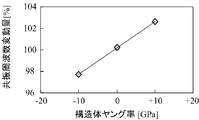
- the horizontal axis indicates the relative value of Young's modulus
- the vertical axis indicates the amount of fluctuation of the resonance frequency.
- the horizontal axis in FIG. 10 is shown as a relative value based on the Young's modulus of the middle data point on the horizontal axis among the three data points.
- the Young's modulus of the structure 110 is basically determined by the type of material constituting the structure 110. However, the Young's modulus of the material generally has temperature dependence. Specifically, even for the same type of material, the Young's modulus decreases as the temperature increases, and the Young's modulus increases as the temperature decreases. Since the resonance frequency depends on the Young's modulus, the resonance frequency also has temperature dependency. Therefore, a change in the ambient temperature in which the optical scanner is placed changes the resonance frequency of the optical scanner.
- Examples of devices that use optical scanners include laser printers and scanning image display devices.
- the scanning speed since the change in the scanning speed results in output distortion, it is desirable that the scanning speed be constant. That is, when an optical scanner that is swung in a resonance state is used, the resonance frequency of the optical scanner is required to be maintained at a predetermined value. However, when the ambient temperature in which the optical scanner is placed changes, the resonance frequency of the optical scanner changes. Therefore, in order to obtain an optical scanner that can be driven stably, the temperature dependence of the resonance frequency needs to be reduced. Therefore, an object of the present disclosure is to provide an optical scanner capable of reducing the temperature dependence of the resonance frequency and a method for manufacturing the optical scanner.
- one aspect of the present disclosure includes a reflecting surface that reflects light and is configured to be swingable about a first axis, and is coupled to both sides of the mirror portion.
- a pair of torsion beam portions extending from the mirror portion in parallel to the first axis and an end of the pair of torsion beam portions on the opposite side of the mirror portion and extending in a direction intersecting the first axis.
- a flat plate-like structure body made of a first material, and provided at least in the structure body, and swinging the mirror part around the first axis at a predetermined resonance frequency.
- a drive unit configured to be configured, and a pedestal formed of a second material and to which the structure is fixed.
- the structure is a part of the main body portion, the pair of torsion beam portions, and the A pair of objects to be opposed across the mirror
- the linear expansion coefficient of the second material is greater than the linear expansion coefficient of the first material
- the absolute value of the temperature dependence of the resonance frequency is such that the pedestal is
- An optical scanner characterized in that it is set to a value smaller than the absolute value of the temperature dependence of the resonance frequency in the case of being constituted by the first material.
- the structure is fixed to at least the pedestal in the pair of fixed portions.
- the pair of fixed parts is a part of the main body part that faces the pair of torsion beam parts and the mirror part.
- the structure and the base are fixed on both sides of the main body portion with the pair of torsion beam portions and the mirror portion interposed therebetween.
- the value of the linear expansion coefficient of the 2nd material which comprises a base is set so that the following 2 conditions may be satisfy
- the linear expansion coefficient of the pedestal is larger than that of the structure, thermal stress is generated in the structure due to temperature change. Specifically, when the temperature rises, the pedestal expands more than the structure. This difference in the amount of expansion applies tension in the longitudinal direction of the torsion beam to the torsion beam part and the mirror part sandwiched between the fixed parts of the base and the structure. When tension is applied to the torsion beam, the rigidity of the torsion beam is apparently increased. The higher the stiffness of the torsion beam, the higher the resonant frequency of the optical scanner. On the other hand, the Young's modulus decreases as the temperature increases. That is, the change in Young's modulus of the first material due to the temperature rise works in the direction of lowering the resonance frequency.
- the thermal stress generated in the structure acts in the direction of increasing the resonance frequency as the temperature rises. Therefore, the temperature dependence of the resonance frequency is reduced.
- the pedestal contracts more than the structure, and thus a force compressing the torsion beam in the longitudinal direction works. That is, the apparent rigidity of the torsion beam is lowered, and the resonance frequency is lowered. Therefore, even when the temperature is lowered, similarly, the change in the resonance frequency due to the change in the Young's modulus of the structure (which works in the direction of increasing) is caused by the difference in the expansion amount between the pedestal and the structure. It is reduced by a change in frequency (which works in the direction of lowering).
- the pedestal is provided by a first material constituted by the second material, and a third material having a linear expansion coefficient different from that of the second material provided between the first layer and the structure.
- a second layer configured, and the second layer may be fixed to the fixed portion of the structure, and the first layer may be fixed to the second layer.
- the pedestal has the first layer and the second layer. Since the first layer and the second layer are made of materials having different linear expansion coefficients, the selection range of the pedestal that can further reduce the temperature dependence of the resonance frequency is expanded depending on the combination of materials.
- the second layer may be configured so that the thickness in the stacking direction is thinner than the first layer.
- the second layer in contact with the structure is thinner in the stacking direction than the first layer. Therefore, the linear expansion coefficient of the entire pedestal is roughly determined by the first layer, and can be finely adjusted by selecting the material of the second layer.
- first material and the second material may be a metal.
- the structure and the pedestal are both made of a metal that is a ductile material. If the structure or pedestal is made of a brittle material such as silicon, for example, depending on the combination of materials, the structure or pedestal may be damaged due to thermal stress. Therefore, the structure and the pedestal are made of metal, thereby increasing the degree of freedom in combining materials. Further, since it can be manufactured by machining such as a press, an optical scanner can be provided at low cost.
- the drive unit is provided in the main body portion, and excites plate waves in the main body portion, thereby swinging the mirror portion around the first axis via the main body portion and the pair of torsion beam portions. It may be a piezoelectric element that can be moved.
- Another aspect of the present disclosure is a method for manufacturing an optical scanner, which includes a reflecting surface that reflects light and is configured to be swingable about a first axis, and is connected to both sides of the mirror portion.
- a pair of torsion beam portions extending from the mirror portion in parallel to the first axis, and a pair of the torsion beam portions opposite to the mirror portion, and intersecting the first axis.
- the temperature of the resonance frequency of the scanner The absolute value of the temperature dependency is minimized among the dependency determination step for determining the dependency and the two or more second material candidates whose temperature dependency is determined by the dependency determination step.
- the pedestal is constituted by the second material that minimizes the temperature dependence of the resonance frequency of the optical scanner. Therefore, an optical scanner in which the temperature dependence of the resonance frequency is reduced can be obtained.
- the acquisition step of acquiring the linear expansion coefficient of the two or more second material candidates, the value of the linear expansion coefficient of the two or more second material candidates, and the dependency determination step are determined.
- a material having a linear expansion coefficient corresponding to a value whose absolute value of temperature dependency is close to a minimum is determined as the second material from the population. May be.
- the second material having the minimum temperature dependence is determined. Therefore, it is possible to determine the second material based on the value of the linear expansion coefficient without determining the temperature dependence of the resonance frequency for all the second material candidates.
- the second layer constituting the second layer provided between the first layer constituted by the second material of the pedestal and the structure is selected from the population.
- a third material determination step for determining a material to be used as the three materials, and the creation step is performed when the temperature dependency is determined not to fall within a predetermined range in the determination step.
- the optical scanner may be manufactured using the pedestal having a material as the first layer of the pedestal and the third material as the second layer.
- a stacked structure pedestal having a first layer and a second layer is created.
- the selection range of the pedestal that can further reduce the temperature dependence of the resonance frequency is expanded.
- the third material determination step when the temperature dependency is a negative value, a material having a linear expansion coefficient larger than that of the second material is determined as the third material, and the temperature dependency is positive. In the case of a value, a material having a smaller linear expansion coefficient than the second material may be determined as the third material.
- the temperature dependence of the resonance frequency of the pedestal made of only the second material is a positive value, in other words, when the resonance frequency also increases with the temperature rise, the line is smaller than the second material.
- a material having an expansion coefficient is determined as the third material constituting the second layer.
- the linear expansion coefficient when it sees with the whole base can be made small, and the temperature dependence of a resonant frequency can be reduced.
- the temperature dependence of the resonance frequency of the pedestal made of only the second material is negative, in other words, when the resonance frequency decreases with increasing temperature, a linear expansion coefficient larger than that of the second material is obtained.
- the material having is determined as the third material constituting the second layer. Thereby, the linear expansion coefficient when it sees with the whole base can be enlarged, and the temperature dependence of a resonant frequency can be reduced.
- an optical scanner capable of reducing the temperature dependence of the resonance frequency and a method for manufacturing the optical scanner are provided.
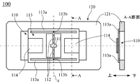
- FIG. 1 is a perspective view of an optical scanner 100 according to a first embodiment.
- the perspective view of the optical scanner 200 based on 2nd Embodiment.
- FIG. 12 is a flowchart for explaining a manufacturing process of the optical scanners 100 and 200 according to the third embodiment.
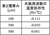
- the flowchart explaining the manufacturing process of the optical scanner in the flowchart of FIG. The figure explaining the change of the temperature dependence of the resonant frequency when the thickness of the 2nd layer 222 of the base 220 changes.
- FIG. 6 is a diagram for explaining the correlation between the Young's modulus of the structure 110 and the resonance frequency of the optical scanner 100.
- the optical scanner 100 includes a structure 110 and a pedestal 120.
- the mirror portion 111 of the structure 110 is swung around the first axis a by the piezoelectric element 114. By this oscillation, the light incident on the mirror portion 111 is scanned.
- the structure 110 is a plate-like structure having a rectangular shape in plan view, which includes a pair of short sides parallel to the first axis a and a pair of long sides orthogonal to the first axis a.
- the structure 110 includes a mirror portion 111, a pair of torsion beam portions 112, and a main body portion 113.
- a piezoelectric element 114 is provided on one surface (for example, the upper surface) of the main body portion 113.
- the structure 110 is made of, for example, a first material that is a metal.
- the structure 110 will be described.
- Mirror portion 111 includes a reflective surface that reflects light such as a laser.
- the shape of the mirror portion 111 is rectangular in plan view.
- the shape of the mirror portion 111 is not limited to this, and may be any shape such as a circle, an ellipse, or a polygon in plan view.
- the reflecting surface is provided by, for example, a method in which the surface of the mirror portion 111 is mirror-polished, or a dielectric such as sapphire or a diamond on which a metal thin film such as aluminum or silver is formed is attached to the mirror portion 111.
- One end of the pair of torsion beam portions 112 is connected to both sides of the mirror portion 111.
- the pair of torsion beam portions 112 each extend in a direction away from the mirror portion 111.
- the extending direction of the pair of torsion beam portions 112 is parallel to the first axis a.
- the first axis a passes through the centers of the pair of torsion beam portions 112.
- the main body portion 113 is connected to the other end of the pair of torsion beam portions 112, that is, the end portion on the opposite side to the mirror portion 111.
- the main body portion 113 is separated from the mirror portion 111 and extends in a direction intersecting the first axis a.
- the main body portion 113 extends from the connecting portion with the pair of torsion beam portions 112 to both sides in the direction orthogonal to the first axis a.
- the main body portion 113 includes a fixed portion 113a and a node coupling portion 113b.
- a pair of fixed portions 113a is provided with a pair of torsion beam portions 112 and a mirror portion 111 interposed therebetween.
- a rectangular through hole is provided at the end of the main body portion 113 in the first axis a direction along a long side orthogonal to the first axis a.
- the region of the main body portion that is located farther from the mirror portion 111 than the through hole is the fixed portion 113a.
- the structure 110 and the pedestal 120 are fixed.
- the node fixing portion 113b is provided at a central portion in a direction orthogonal to the first axis a of the rectangular through hole. The node fixing portion 113b extends in the first axis a direction.
- the node fixing portion 113b connects the body portion 113 closer to the mirror portion 113 than the rectangular through hole and the fixed portion 113a. More specifically, the node fixing portion 113b is positioned in the same straight line as the pair of torsion beam portions 112. Thereby, the thermal stress due to the difference in linear expansion coefficient between the structure 110 and the pedestal 120 is efficiently converted into tension / contraction of the pair of torsion beam portions 112 via the node fixing portion 113b.
- a piezoelectric element 114 as a driving unit is provided on the upper surface of the main body portion 113.
- a pair of the piezoelectric elements 114 is provided at both ends of the main body portion 113 in the first axis a direction and in the direction orthogonal to the first axis a.
- the piezoelectric element 114 is formed by laminating 0.2 ⁇ m to 0.6 ⁇ m of gold, platinum, or the like as an electrode layer on both surfaces of a piezoelectric material such as lead zirconate titanate formed into a flat plate having a thickness of 30 ⁇ m to 100 ⁇ m. It is formed by doing.
- the piezoelectric element 114 and the main body portion 113 are bonded with a conductive adhesive.
- a thin metal wire (not shown) such as gold is connected to the upper surface of the piezoelectric element 114 by wire bonding or the like.
- the pedestal 120 has a rectangular shape in plan view.
- the pedestal 120 has a rectangular hole that is hollowed out in a rectangular shape at the center.
- the fixed portion 113 a of the structure 110 is fixed to an adjacent portion of the rectangular hole of the pedestal 120.
- the thickness of the pedestal 120 is sufficiently larger than the thickness of the structure 110. Therefore, even if the structure 110 swings, the pedestal 120 hardly deforms.
- the pedestal 120 has a single layer structure including only the first layer 121.
- the second material constituting the first layer 121 is, for example, a metal having a linear expansion coefficient different from that of the first material constituting the structure 110. More specifically, the value of the linear expansion coefficient of the second material is set so as to satisfy the following two conditions. (1) A value greater than the linear expansion coefficient of the first material, (2) the temperature of the resonance frequency when the pedestal 120 is made of the same first material as the structure 110, and the absolute value of the temperature dependence of the resonance frequency. A value that is smaller than the absolute value of the dependency.
- the piezoelectric element 114 can be deformed by applying a voltage between the structure 110 and the electrode layer on the upper surface of the piezoelectric element 114.
- An AC voltage is applied to the piezoelectric element 114 provided on one side with respect to the first axis a and the piezoelectric element 114 provided on the other side so as to be in opposite phases.
- the frequency of the AC voltage corresponds to the resonance frequency of the optical scanner 100, a plate wave is excited in the main body portion 114 as the piezoelectric element 114 is deformed.
- the plate wave is transmitted to the mirror portion 111 through the main body portion 113 and the pair of torsion beam portions 112, so that the mirror portion 111 swings around the first axis a at a predetermined resonance frequency. That is, since the optical scanner 100 is a so-called external excitation type optical scanner, a large deflection angle can be obtained.
- the structure 110 is fixed to the pedestal 120 at the fixed portion 113a, and the main body portion 113 sandwiched between the fixed portions 113a is in a state of being suspended in the air by the pedestal 120. Therefore, when the optical scanner 100 is driven, the main body portion 113 is displaced in the vertical direction.
- the torsion beam portion 112 is provided at a position that becomes a vibration node of the main body portion 113, even if the main body portion 113 is displaced up and down, the torsion beam portion 112 is not displaced up and down. Further, a node fixing portion 113 b provided on the same straight line as the torsion beam portion 112 connects the fixed portion 113 a and the torsion beam portion 112. Therefore, the torsion beam portion 112 is further suppressed from being displaced in the vertical direction. Therefore, when the mirror portion 111 is swung around the first axis a, the vertical displacement is suppressed. Accordingly, the light incident on the mirror portion 111 is always incident on the same position on the mirror portion 111, so that stable light scanning is possible.
- the linear expansion coefficient of the pedestal 120 is larger than that of the structure 110, thermal stress is generated in the structure 110 due to temperature change. Specifically, when the temperature rises, the pedestal 120 expands more than the structure. This difference in expansion amount applies tension in the direction of the first axis a to the pair of torsion beam portions 112 and the mirror portion 111 sandwiched between the fixed portions of the base 120 and the structure 110. When tension is applied to the pair of torsion beam portions 112, the rigidity of the pair of torsion beam portions 112 is apparently increased. The higher the rigidity of the pair of torsion beam portions 112 is, the higher the resonance frequency of the optical scanner 100 is. On the other hand, the Young's modulus decreases as the temperature increases.
- the change in Young's modulus of the first material due to the temperature rise works in the direction of lowering the resonance frequency.
- the linear expansion coefficient of the second material is larger than the linear expansion coefficient of the first material, the thermal stress generated in the structure 110 acts in the direction of increasing the resonance frequency as the temperature rises. Therefore, the temperature dependence of the resonance frequency is reduced. Note that, when the temperature is lowered, the pedestal 120 contracts more than the structure 110, and thus a force that compresses the pair of torsion beam portions 112 in the longitudinal direction acts. That is, the apparent rigidity of the pair of torsion beam portions 112 decreases, and the resonance frequency decreases.
- the change in the resonance frequency caused by the change in the Young's modulus of the structure 110 (which works in the direction of increasing) is caused by the difference in expansion amount between the pedestal 120 and the structure 110. It is reduced by the change in the resonance frequency (which works in the direction of lowering).
- Both the structure 110 and the pedestal 120 are made of a metal that is a ductile material. If the structure 110 or the pedestal 120 is made of a brittle material such as silicon, the structure 110 or the pedestal 120 may be damaged due to thermal stress depending on the combination of materials. Therefore, the structure 110 and the pedestal 120 are made of metal, so that the degree of freedom in combining materials increases. Further, since it can be manufactured by machining such as a press, the optical scanner 100 can be provided at low cost.
- the temperature dependence of the resonance frequency is shown in units of the amount of change in the resonance frequency (Hz / ° C.) with respect to a temperature increase of 1 ° C.
- the absolute value of the temperature dependence differs even for the same material due to various indeterminates such as the bonding conditions between the pedestal 120 and the structure 110 and the size variation in manufacturing. .
- the tendency was found that the greater the linear expansion coefficient of the material of the pedestal 120, the greater the temperature dependence of the resonance frequency. More specifically, when the pedestal 120 is configured by SUS420, the temperature dependence of the resonance frequency is ⁇ 0.5 to ⁇ 0.6 [Hz / ° C.] in both simulation and measurement.
- the temperature dependence of the resonance frequency when the pedestal 120 is formed of SUS420 can be regarded as a value when the linear expansion coefficients of the structure 110 and the pedestal 120 are substantially the same. Since the Young's modulus decreases with increasing temperature, when the linear expansion coefficient of the structure 110 and the pedestal 120 is substantially the same, the temperature dependence of the resonance frequency shows a negative value (the higher the temperature, the lower the resonance frequency). ).
- the temperature dependence of the resonant frequency will be relieved. As described above, this is because the pair of torsion beam portions 112 are pulled by the thermal stress acting on the structure 110 due to the difference in the linear expansion coefficient between the structure 110 and the pedestal 120, and apparently a pair of torsion. This is because the rigidity of the beam portion 112 increases. According to the result of FIG. 2, when SECC and SUS309 are used for the pedestal 120, the temperature dependence of the resonance frequency is alleviated as compared to the case where the pedestal 120 is made of the same material as the structure 110.
- the material that minimizes the absolute value of the temperature dependence of the resonance frequency may be determined as a constituent material of the pedestal 120 based on this result.
- the pedestal 120 is formed using SECC.
- the base 120 is formed using SECC or SUS309. Thereby, the optical scanner 100 in which the temperature dependency of the resonance frequency is reduced is obtained.
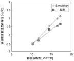
- the correlation between the two is examined by taking the linear expansion coefficient of the material of the pedestal 120 on the horizontal axis and the temperature dependence of the resonance frequency on the vertical axis.
- FIG. 3 there is a positive correlation, more specifically, a linear relationship between the linear expansion coefficient of the constituent material of the pedestal 120 and the temperature dependence of the resonance frequency.
- the difference in the temperature dependence of the resonance frequency between the simulation and the actual measurement is shown in FIG. 3 as a difference in proportionality coefficient.
- a material that minimizes the absolute value of the temperature dependence of the resonance frequency can be selected as the material of the pedestal 120.
- the proportionality coefficient between the linear expansion coefficient and the temperature dependence of the resonance frequency can be determined.
- this proportionality factor is used, the material whose resonance frequency temperature dependency is minimized can be obtained only for the material whose resonance frequency temperature dependency is not determined, based only on the value of the linear expansion coefficient. Selection becomes possible.
- Second Embodiment 4A and 4B show another preferred embodiment of the present invention.
- the optical scanner 200 includes a structure 210 and a pedestal 220.
- the optical scanner 200 is different from the optical scanner 100 described above in the configuration of the base 220.
- the structure 210 includes a mirror portion 211, a pair of torsion beam portions 212, and a main body portion 213.
- a piezoelectric element 214 is provided on the upper surface of the main body portion 213.
- the pedestal 220 has a first layer 221 and a second layer 222.
- the constituent material of the first layer 221 and the constituent material of the second layer 222 are metals having different linear expansion coefficients. Therefore, the selection range of the pedestal 220 that can further reduce the temperature dependence of the resonance frequency is expanded depending on the combination of materials.
- the second layer 222 has a rectangular shape in plan view, and has a rectangular hole cut out in a rectangular shape at the center.
- the second layer 222 is fixed to the fixed portion 213a of the structure 210, similarly to the first layer 121 in the above-described embodiment.
- the first layer 221 is formed in the same manner as the second layer 222 in plan view.
- the first layer 221 is fixed to the lower surface of the second layer 222.
- one surface (upper surface) of the second layer 222 is fixed to the structure 210, and the other surface (lower surface) is fixed to the first layer 221.
- the thickness of the second layer 222 is thinner than the thickness of the first layer 221.
- the thickness of the first layer 221 is about 2 mm
- the thickness of the second layer 222 is set to about 0.4 mm.
- the thickness of the structure 210 is about 0.1 mm, for example.
- FIG. 5 shows the temperature dependence of the resonance frequency obtained by simulation when the material of the second layer 222 is combined with the material of the first layer 221 in the optical scanner 200 shown in FIGS. 4A and 4B. It is a figure which shows a result.
- SUS420 10.3 ⁇ 10 -6 [/°C]
- SECC 11.7 ⁇ 10 -6 [/ °C]
- the structure 210 is formed of SUS430 as in the case of the optical scanner 100.
- high function spring steel for example, HT2000 manufactured by Nisshin Steel Co., Ltd. can be used.
- the temperature dependency of the resonance frequency changes when the material of the first layer 221 is fixed and the material of the second layer 222 is changed.
- the temperature dependence of the resonance frequency of both is about 0.2 [Hz / ° C.] regardless of the material of the first layer 221.
- the temperature dependence of the resonance frequency tends to increase as a material having a large linear expansion coefficient is used for the second layer 222.
- the temperature dependence of both resonance frequencies is about 0.5 to 0.8 [Hz. / ° C].
- the linear expansion coefficient of the entire pedestal 220 is roughly determined by the first layer 221 having a large thickness, and can be finely adjusted by selecting the material of the second layer 222.
- the material of the first layer 221 is selected so that the absolute value of the temperature dependency of the resonance frequency is minimized, and then the material of the second layer 222 is selected, so that the temperature of the resonance frequency is selected.
- the dependency can be made closer to 0.
- the temperature dependency of the resonance frequency is a negative value, and thus the second layer 222 is configured with a material having a larger linear expansion coefficient than the first layer 221.
- the temperature dependency of the resonance frequency can be further reduced.
- the temperature dependency of the resonance frequency is a positive value, and therefore the second layer 222 is configured with a material having a smaller linear expansion coefficient than the first layer 221. By doing so, the temperature dependence of the resonance frequency can be further reduced.
- step S1 the linear expansion coefficient of the first material constituting the optical scanner structure (structure 110 or structure 210 of the above-described embodiment) is acquired.
- the material constituting the structure is selected in advance according to, for example, the design value of the resonance frequency of the optical scanner.
- the linear expansion coefficient may be obtained by directly measuring the material, or may be obtained by utilizing an existing value such as a data sheet.
- step S2 the temperature dependence of the Young's modulus of the material constituting the structure is obtained.
- the Young's modulus of the structure affects the resonance frequency of the optical scanner.
- the higher the Young's modulus the higher the resonant frequency. Therefore, by obtaining the temperature dependence of the Young's modulus, the temperature dependence of the resonance frequency of the optical scanner caused only by the structure can be understood.
- the temperature dependence of the Young's modulus may be acquired by any method such as application of a mathematical formula using an existing value such as a data sheet as a coefficient, actual measurement, or the like.
- a candidate for the second material constituting the pedestal is determined, and its linear expansion coefficient is acquired.
- a plurality of materials having different linear expansion coefficient values exist as a candidate population as the second material.
- This population includes a material having a linear expansion coefficient larger than that of the first material constituting the structure.
- a material having a linear expansion coefficient smaller than that of the first material may be included in this population.
- one material for example, SUS420
- acquisition of a linear expansion coefficient may be achieved by arbitrary methods, such as using measurement and the value of a data sheet.
- step S4 the temperature dependence of the Young's modulus of the second material candidate determined in step S3 is acquired.
- the temperature dependence of the Young's modulus may be obtained by any method such as a mathematical expression using an existing value such as a data sheet as a coefficient, or actual measurement.
- step S5 the temperature dependence of the resonance frequency in the optical scanner in which the second material candidate is used for the pedestal is determined.
- This step is achieved, for example, by actually creating an optical scanner and measuring the resonance frequency of the optical scanner while changing the ambient temperature in which the optical scanner is placed.
- the resonance frequency may be determined from, for example, the timing of the scanning light detected by the optical sensor disposed at the position where the light scanned by the optical scanner enters.
- the temperature dependence of the resonance frequency of the optical scanner may be obtained using simulation.
- the temperature dependency of the resonance frequency is obtained for two or more second material candidates, based on the correlation between the temperature dependency of the resonance frequency and the linear expansion coefficient of the material.
- the temperature dependence of the resonance frequency is obtained from the value of the linear expansion coefficient.
- FIG. 2A or FIG. 2B it is assumed that the temperature dependence of the resonance frequency is obtained by actual measurement when a pedestal is constituted by SUS420 and SUS304.
- a proportional coefficient between the linear expansion coefficient and the temperature dependence of the resonance frequency is determined using the linear expansion coefficients of SUS420 and SUS304 obtained in step S3. If this proportionality coefficient is used, for example, the temperature dependence of the resonance frequency can be determined when the pedestal is constituted by SECC, SUS309, and SUS316 that are not actually measured.
- the temperature dependence of the resonance frequency when the material is used for the pedestal can be determined based only on the value of the linear expansion coefficient of the material. If further expanding, even if the material is not included in the population as a candidate for the second material (for example, a material not shown in FIG. 2), only the value of the linear expansion coefficient of the material is used. Based on this, the temperature dependence of the resonance frequency can be determined.
- step S6 it is determined whether or not the absolute value of the temperature dependence of the resonance frequency of the second material candidate determined in step S3 is the minimum. If the absolute value of the temperature dependence of the resonance frequency of the second material candidate is minimum (S6: Y), after the second material candidate is determined as the second material constituting the pedestal in step S7. The process proceeds to step S8. On the other hand, when the absolute value of the temperature dependence of the resonance frequency of the second material candidate is not minimum (S6: N), the process proceeds to step S8. For example, in the case where SUS420 is first determined as the second material candidate in FIG. 2A or FIG. 2B, there is no second material candidate determined before that, so the absolute frequency dependence of the resonance frequency of SUS420 is absolute.
- step S6: Y The value is minimized (step S6: Y). Therefore, SUS420 is determined as the second material constituting the pedestal (S7).
- SECC is determined as the second material candidate after SUS420, the absolute value of the temperature dependence of the resonance frequency of SECC is smaller than the absolute value of the temperature dependence of the resonance frequency of SUS420. Therefore, the absolute value of the temperature dependence of the SECC resonance frequency is minimized (step S6: Y). Therefore, instead of SUS420, SECC is determined as the second material constituting the pedestal (S7).
- SUS309 is determined as the second material candidate after SECC, the absolute value of the temperature dependence of the resonance frequency of SUS309 is larger than the absolute value of the temperature dependence of the resonance frequency of SECC. For this reason, the absolute value of the temperature dependence of the resonance frequency of SECC remains minimal (step S6: N). In this case, since step S7 is not performed, the second material constituting the pedestal remains SECC.
- step S8 it is determined whether other second material candidates still remain in the population. If other second material candidates still remain (S8: Y), the process returns to step S3, and steps S3 to S7 are performed on the other second material candidates. On the other hand, when no other second material candidates remain, in other words, when the study on all second material candidates included in the population is completed (S8: N), the process proceeds to step S9.
- step S9 it is determined whether or not the temperature dependency of the resonance frequency when using the pedestal material determined in step S7 is within the specification range.
- the range of this specification may be determined based on the performance of a printer such as a printer that uses an optical scanner or a scanning image display device. Alternatively, the performance of the optical scanner alone may be set to a predetermined value.
- an optical scanner is created using the base material (S11). That is, in this case, the above-described optical scanner 100 having a pedestal formed of a single layer is produced.
- the temperature dependency of the resonance frequency does not fall within the specification range (S9: N)
- the temperature dependency of the resonance frequency is further reduced by forming the pedestal in a laminated structure as in the optical scanner 200 described above. Consideration is made (S10).
- step S100 it is determined whether or not the temperature dependence (obtained in step S5) of the resonance frequency of the second material determined in step S7 is a positive value.
- SECC is determined as the second material.
- the temperature dependence of the resonance frequency is negative ( ⁇ 0.162 [Hz / ° C. in simulation, ⁇ 0.323 [Hz / ° C.] in actual measurement). Is denied (S100: N).
- step S102 is performed.
- step S110 is affirmed (S100: Y).
- step S101 is performed.
- step S101 a material having a smaller linear expansion coefficient than the material of the first layer 221 is selected as the material of the second layer 222 of the base 220.
- the substantial linear expansion coefficient of the entire pedestal 220 can be reduced, and the temperature dependence of the resonance frequency can be brought close to zero.
- SUS304 is determined as the material of the first layer 221
- high-function spring steel or SUS430 which is a material having a smaller coefficient of linear expansion than SUS304, is determined as the material of the second layer 222. (See FIG. 5).
- SUS304 is determined as the material of the first layer 221
- SUS430 which is a material having a smaller coefficient of linear expansion than SUS304
- step S102 a material having a larger linear expansion coefficient than the material of the first layer 221 is selected as the material of the second layer 222 of the base 220.
- the substantial linear expansion coefficient of the entire pedestal 220 can be increased, and the temperature dependence of the resonance frequency can be brought close to zero.
- SECC is determined as the material of the first layer 221
- high-function spring steel or SUS304 which is a material having a larger linear expansion coefficient than SECC
- step S11 of FIG. 6 an optical scanner is created.
- the optical scanner 100 including the pedestal 120 made of a single layer is formed.
- the optical scanner 200 including the base 220 having the first layer 221 and the second layer 222 is formed. Details of step S11 are shown in FIG.
- a structure is formed by a predetermined removal process.
- wet etching is employed as an example of removal processing.
- a metal plate (for example, SUS430) constituting the structure is divided into a size equal to the outer shape of the structure.
- a resist film for masking is formed at positions corresponding to the mirror portion, the torsion beam portion, and the main body portion of the divided metal plate.
- the resist film is removed.
- the structure may be formed not by wet etching but by mechanical processing such as press processing.
- a bulk piezoelectric material provided with electrode layers on both surfaces of the piezoelectric element in advance is mounted on the structure.
- This mounting is performed using, for example, a conductive adhesive containing a conductive material such as a metal filler in a synthetic resin material such as epoxy, acrylic or silicon.
- a bulk piezoelectric material is placed on a conductive adhesive applied to the main body portion of the structure.
- the conductive adhesive is cured by placing the structure in a heating furnace maintained at 100 to 200 ° C. for 30 to 60 minutes. This completes the mounting of the piezoelectric element.
- a pedestal is created.
- the outer shape of the pedestal can be obtained by performing removal processing such as etching or pressing on the metal plate that is a constituent material of the pedestal, as in the case of the structure.
- the metal plate for constituting the first layer and the metal plate for constituting the second layer are respectively subjected to removal processing. Is done. Note that the thicknesses of the first layer and the second layer are automatically set by processing a metal plate having a corresponding thickness. Thereafter, the first layer and the second layer are fixed by adhesion, welding, or the like.
- step S113 the base and the structure are fixed.
- This fixing is performed, for example, by welding the fixed portion of the structure and the pedestal by laser welding or the like.
- the structure and the base may be fixed by other fixing methods such as bonding using a thermosetting adhesive.
- step S114 the signal line is connected to the piezoelectric element and the structure by wire bonding.
- This signal line is connected to an AC power source (not shown). Since the structure and the piezoelectric element are bonded by a conductive adhesive, a voltage is applied between the piezoelectric element and the structure via the signal line. This completes the optical scanner manufacturing process.
- the pedestal 220 has a first layer 221 and a second layer 222.
- this embodiment does not exclude a configuration in which the pedestal has a laminated structure of three or more layers.
- the materials for the third and subsequent layers may be determined after the materials for the first layer and the second layer are determined as described above.
- the material of the second layer 222 is determined to reduce the temperature dependence of the resonance frequency using the type of the constituent material, more specifically, the linear expansion coefficient of the constituent material as a variable.
- other variables that determine the structure of the second layer 222 may be further introduced to reduce the temperature dependence of the resonance frequency.
- the structure 210 is made of SUS430
- the first layer 221 of the base 220 is made of SECC
- the second layer 222 is made of SUS304.
- the thickness of the structure 210 is set to 100 ⁇ m
- the thickness of the first layer 221 is set to 2000 ⁇ m.
- the temperature dependence of the resonance frequency increases as the second layer 222 becomes thicker. That is, for example, a step of determining the thickness of the second layer 222 may be performed after step S101 or step S102 shown in FIG. This makes it possible to determine the structure of the pedestal so that the absolute value of the temperature dependence of the resonance frequency is further reduced by using the variable of the pedestal thickness in addition to the variable of the linear expansion coefficient.
- the structure and the base are made of metal.
- the present disclosure is characterized in that the temperature dependence of the resonance frequency is mitigated by making the linear expansion coefficients of the structure and the pedestal different. Therefore, even if the base and the structure are made of a nonmetal such as silicon, the scope of the present disclosure is included.
- the shapes of the structure and the pedestal are not limited to the above-described embodiments. Any type of optical scanner in which a flat plate-like structure having a mirror portion, a torsion beam portion, and a main body portion is fixed to a pedestal is included in the scope of the present invention.
- a piezoelectric element is used as the drive unit.
- an optical scanner that employs another driving method such as an electromagnetic driving method using a combination of a magnet and a coil pattern or an electrostatic driving method using an electrostatic force acting between electrode plates, is included in the scope of the present disclosure. .
- Optical scanner 110 210 Structure 111, 211 Mirror part 112, 212 Torsion beam part 113, 213 Body part 113a, 213a Fixed part 113b, 213b Node connecting part 114, 214 Piezoelectric element 120, 220 Base 121, 221 First layer 222 second layer
Landscapes
- Physics & Mathematics (AREA)
- General Physics & Mathematics (AREA)
- Optics & Photonics (AREA)
- Mechanical Optical Scanning Systems (AREA)
- Mechanical Light Control Or Optical Switches (AREA)
- Micromachines (AREA)
Abstract
第1材料によって構成される平板状の構造体と、台座とを備える光スキャナである。構造体は、ミラー部分と、その一端がミラー部分の両側に連結される一対の捩れ梁部分と、一対の捩れ梁部分の他端に連結される本体部分とを有する。構造体には、ミラー部分を所定の共振周波数にて揺動可能な駆動部が設けられる。構造体は、本体部分の一部であって一対の捩れ梁部分及びミラー部分を挟んで対向する一対の被固定部分において、少なくとも台座に固定される。台座を構成する第2材料の線膨張係数は、第1材料の線膨張係数よりも大きな値であって、共振周波数の温度依存性の絶対値が、台座が第1材料によって構成された場合の共振周波数の温度依存性の絶対値よりも小さくなるような値に設定される。
Description
本発明は、レーザ等の光を走査する光スキャナ及び光スキャナの製造方法に関する。
現在、振動するミラーによりレーザ光などの光を走査する光スキャナが知られている。例えば、特許文献1に記載の光スキャナは、捩れ梁部で揺動可能に支持されたミラーが、圧電素子などの駆動部によって共振状態にて揺動することにより、ミラーに入射する光を走査する。そして、ミラーを含む構造体(本体部)は、台座(ベース)に固定されている。
光スキャナの共振周波数は、様々な要因によって変化する。例えば、光スキャナの共振周波数は、ミラーを含む構造体のヤング率に依存して変化する。この説明として、図1に示される光スキャナ100の形状において、構造体110を異なるヤング率(=剛性)の材料で形成した場合の、光スキャナ100の共振周波数の振る舞いを、図10に示す。図10では、横軸にヤング率の相対値が、縦軸に共振周波数の変動量が、それぞれ示される。なお、図10の横軸は、3点あるデータ点のうち、横軸において真ん中のデータ点のヤング率を基準とした相対値で示される。図10の縦軸は、3点あるデータ点のうち、縦軸において真ん中のデータ点の共振周波数を基準(100%)として、その値からの変動量の割合が示される。図10から明らかに、ヤング率と共振周波数とは、正比例の関係にある。構造体110のヤング率は、基本的には、構造体110を構成する材料の種類によって決まる。しかし、材料のヤング率は、一般に温度依存性を有する。具体的には、同一種類の材料であっても、温度が高くなればヤング率が下がり、温度が低くなればヤング率が上がる。共振周波数はヤング率に依存するので、共振周波数も温度依存性を有する。従って、光スキャナが置かれる雰囲気温度の変化は、光スキャナの共振周波数に変化をもたらす。
光スキャナが利用される装置としては、例えば、レーザープリンタや走査型画像表示装置などが考えられる。これらの装置では、走査速度の変化は出力の歪みとなるため、走査速度は一定であることが望まれる。即ち、共振状態で揺動される光スキャナが利用される場合、光スキャナの共振周波数は、所定の値に保たれることが要求される。しかし、光スキャナが置かれる雰囲気温度が変化した場合、光スキャナの共振周波数が変化する。従って、安定して駆動可能な光スキャナを得るためには、この共振周波数の温度依存性が低減される必要がある。そこで、本開示は、共振周波数の温度依存性を低減することが可能な光スキャナと、その光スキャナの製造方法とを提供することを目的とする。
上記課題を解決するために、本開示の一側面は、光を反射する反射面を含み、第1軸線を中心として揺動可能に構成されるミラー部分と、前記ミラー部分の両側に連結され、前記第1軸線に平行に前記ミラー部分から延出する一対の捩れ梁部分と、前記一対の捩れ梁部分の前記ミラー部分反対側の端部に連結され、前記第1軸線に交差する方向に延出する本体部分と、を有し、第1材料によって構成される平板状の構造体と、少なくとも前記構造体に設けられ、前記ミラー部分を所定の共振周波数にて前記第1軸線回りに揺動可能に構成される駆動部と、第2材料によって構成され、前記構造体が固定される台座とを備え、前記構造体は、前記本体部分の一部であって前記一対の捩れ梁部分及び前記ミラー部分を挟んで対向する一対の被固定部分において、少なくとも前記台座に固定され、前記第2材料の線膨張係数は、前記第1材料の線膨張係数よりも大きく、且つ、前記共振周波数の温度依存性の絶対値が、前記台座が前記第1材料によって構成された場合の前記共振周波数の温度依存性の絶対値よりも小さくなる値に設定される、ことを特徴とする光スキャナである。
これによれば、構造体は、一対の被固定部分において、少なくとも台座に固定される。そして、一対の被固定部分は、一対の捩れ梁部分及びミラー部分を挟んで対向する、本体部分の一部分である。換言すれば、一対の捩れ梁部分及びミラー部分を間に挟んだ本体部分の両側において、構造体と台座とが固定される。そして、台座を構成する第2材料の線膨張係数の値は、以下の2条件を満たすように設定される。(1)構造体を構成する第1材料の線膨張係数よりも大きな値、(2)共振周波数の温度依存性の絶対値が、台座が第1材料によって構成された場合の絶対値よりも小さくなる値。ここで、構造体よりも台座の線膨張係数が大きいので、温度変化によって構造体に熱応力が発生する。具体的には、温度が上昇すると、台座が構造体よりも多く膨張する。この膨張量の差は、台座と構造体との固定部分に挟まれた捩れ梁部分及びミラー部分に対して、捩れ梁の長手方向に張力を与える。捩れ梁に張力がかかると、見かけ上、捩れ梁の剛性が上昇する。捩れ梁の剛性が高いほど、光スキャナの共振周波数は高くなる。一方、ヤング率は、温度が上昇するほど減少する。即ち、温度上昇に起因する第1材料のヤング率変化は、共振周波数を低くする方向に働く。しかし、第2材料の線膨張係数が第1材料の線膨張係数よりも大きいので、構造体に発生する熱応力は、温度上昇に伴い共振周波数を高くする方向に働く。従って、共振周波数の温度依存性が低減される。なお、温度が下降する場合は、台座が構造体よりも多く収縮するため、捩れ梁を長手方向に圧縮する力が働く。即ち、捩れ梁の見かけ上の剛性が低下し、共振周波数は低下する。従って、温度が下降する場合であっても同様に、構造体のヤング率変化に起因する共振周波数の変化(高くする方向に働く)は、台座と構造体との膨張量の差に起因する共振周波数の変化(低くする方向に働く)によって低減される。
また、前記台座は、前記第2材料によって構成される第1層と、前記第1層と前記構造体との間に設けられ、前記第2材料とは異なる線膨張係数を有する第3材料によって構成される第2層とを有し、前記第2層は、前記構造体の前記被固定部分に固定され、前記第1層は、前記第2層に固定されてもよい。
これによれば、台座が第1層と第2層とを有する。第1層と第2層は異なる線膨張係数を有する材料によって構成されるので、材料の組み合わせによって、より共振周波数の温度依存性を低減可能な台座の選択範囲が広がる。
さらに、前記第2層は、前記第1層よりも積層方向における厚みが薄くなるように構成されてもよい。
これによれば、構造体に接する第2層は、第1層よりも積層方向における厚みが薄い。従って、台座全体での線膨張係数は第1層によって大枠が決められ、第2層の材質を選択することで、細かな調整が可能となる。
さらに、前記第1材料及び前記第2材料は、金属であってよい。
これによれば、構造体及び台座が、ともに延性材料である金属から構成される。仮に、例えばシリコンなどの脆性材料で構造体や台座が構成された場合、材料の組み合わせによっては、熱応力が原因で、構造体や台座が破損する可能性がある。そのため、構造体及び台座が金属から構成されることで、材料の組み合わせの自由度が増す。また、プレスなどの機械加工による製造も可能となるため、低コストで光スキャナを提供できる。
さらに、前記駆動部は、前記本体部分に設けられ、前記本体部分に板波を励起することで、前記本体部分及び前記一対の捩れ梁部分を介して前記ミラー部分を前記第1軸線回りに揺動させることが可能な圧電素子であってもよい。
これにより、圧電素子によって励起された板波がミラーを揺動させる、いわゆる外部励振型の光スキャナが得られる。従って、大きな振れ角が得られる。
本開示の他の側面は、光スキャナの製造方法であって、光を反射する反射面を含み、第1軸線を中心として揺動可能に構成されるミラー部分と、前記ミラー部分の両側に連結され、前記第1軸線に平行に前記ミラー部分から延出する一対の捩れ梁部分と、前記一対の捩れ梁部分の前記ミラー部分反対側の端部に連結され、前記第1軸線に交差する方向に延出する本体部分とを有する構造体を構成する第1材料の線膨張係数よりも大きい値であって、互いに異なる線膨張係数の値を有する複数の材料を含む母集団から、前記構造体が固定される台座を構成する前記第2材料としての候補となる材料である第2材料候補を決定する候補決定工程と、前記第2材料候補を前記第2材料として用いた場合における、前記光スキャナの共振周波数の温度依存性を決定する依存性決定工程と、前記依存性決定工程によって前記温度依存性が決定された2つ以上の前記第2材料候補の中から、前記温度依存性の絶対値が最小となった前記第2材料候補を、前記第2材料として決定する第2材料決定工程と、前記第2材料決定工程によって決定された前記第2材料を用いて、前記光スキャナを作成する作成工程と、有することを特徴とする光スキャナの製造方法である。
これによれば、光スキャナの共振周波数の温度依存性が最小となる第2材料によって、台座が構成される。従って、共振周波数の温度依存性が低減された光スキャナが得られる。
また、前記2つ以上の前記第2材料候補の線膨張係数を取得する取得工程と、前記2つ以上の前記第2材料候補の線膨張係数の値と、前記依存性決定工程によって決定された前記2つ以上の第2材料候補における前記温度依存性との相関関係を決定する関係決定工程をさらに備え、前記第2材料決定工程は、前記関係決定工程によって決定された前記相関関係に基づいて、前記2つ以上の前記第2材料候補に加えて、前記母集団の中から前記温度依存性の絶対値が最小に近い値に対応する線膨張係数を有する材料を、前記第2材料として決定してもよい。
これによれば、線膨張係数と、共振周波数の温度依存性との相関関係に基づいて、温度依存性が最小となる第2材料が決定される。従って、全ての第2材料候補に対して共振周波数の温度依存性を決定しなくても、その線膨張係数の値に基づいて、第2材料としての決定が可能となる。
さらに、前記第2材料決定工程によって決定された前記第2材料における前記温度依存性が、所定の範囲内に収まるか否かを判断する判断工程と、前記判断工程において前記温度依存性が所定の範囲内に収まらないと判断された場合に、前記母集団の中から、前記台座の前記第2材料によって構成される第1層と前記構造体との間に設けられる第2層を構成する第3材料として用いる材料を決定する第3材料決定工程とをさらに有し、前記作成工程は、前記判断工程において前記温度依存性が所定の範囲内に収まらないと判断された場合に、前記第2材料を前記台座の前記第1層とし、前記第3材料を前記第2層とする前記台座を用いて、前記光スキャナを製造してもよい。
これによれば、共振周波数の温度依存性が所定の範囲内に収まらない場合、第1層と第2層とを有する積層構造の台座が作成される。第1層と第2層との材料の組み合わせによって、より共振周波数の温度依存性を低減可能な台座の選択範囲が広がる。
さらに、前記第3材料決定工程は、前記温度依存性が負の値の場合、前記第2材料よりも大きな線膨張係数を有する材料を前記第3材料として決定し、前記温度依存性が正の値の場合、前記第2材料よりも小さな線膨張係数を有する材料を前記第3材料として決定してもよい。
これによれば、第2材料のみで構成された台座の共振周波数の温度依存性が正の値の場合、換言すれば、温度上昇に伴い共振周波数も上昇する場合、第2材料よりも小さな線膨張係数を有する材料が、第2層を構成する第3材料として決定される。これにより、台座全体で見たときの線膨張係数を小さくすることができ、共振周波数の温度依存性を低減できる。一方、第2材料のみで構成された台座の共振周波数の温度依存性が負の値の場合、換言すれば、温度上昇に伴い共振周波数が低下する場合、第2材料よりも大きな線膨張係数を有する材料が、第2層を構成する第3材料として決定される。これにより、台座全体で見たときの線膨張係数を大きくすることができ、共振周波数の温度依存性を低減できる。
本発明によれば、共振周波数の温度依存性を低減することが可能な光スキャナと、その光スキャナの製造方法とが提供される。
<第1実施形態>
以下に図面を参照しつつ、本開示の一側面に係る実施の形態を示す。なお、本開示の一側面は以下に記載の構成に限定されるものではなく、同一の技術的思想において種々の構成を採用することができる。例えば、以下に説明する各構成において、所定の構成を省略し、または他の構成などに置換してもよい。また、他の構成を含むようにしてもよい。
以下に図面を参照しつつ、本開示の一側面に係る実施の形態を示す。なお、本開示の一側面は以下に記載の構成に限定されるものではなく、同一の技術的思想において種々の構成を採用することができる。例えば、以下に説明する各構成において、所定の構成を省略し、または他の構成などに置換してもよい。また、他の構成を含むようにしてもよい。
[光スキャナ100の構成]
図1A及び図1Bに示されるように、光スキャナ100は、構造体110と、台座120とを有する。構造体110のミラー部分111は、圧電素子114によって、第1軸線aを中心軸として揺動する。この揺動によって、ミラー部分111に入射した光は走査される。
図1A及び図1Bに示されるように、光スキャナ100は、構造体110と、台座120とを有する。構造体110のミラー部分111は、圧電素子114によって、第1軸線aを中心軸として揺動する。この揺動によって、ミラー部分111に入射した光は走査される。
構造体110は、第1軸線aに平行な一対の短辺と、第1軸線aに直交する一対の長辺とから構成される、平面視矩形の板状構造である。構造体110は、ミラー部分111、一対の捩れ梁部分112、本体部分113を有する。本体部分113の一方の面(例えば、上面)には、圧電素子114が設けられる。構造体110は、例えば、金属である第1材料によって構成される。以下、構造体110の説明を行う。
ミラー部分111は、レーザ等の光を反射する反射面を含む。ミラー部分111の形状は、本実施形態では、平面視において矩形である。しかし、ミラー部分111の形状は、これに限定されず、平面視において円形、楕円形、多角形など、任意の形状であっても差し支えない。反射面は、例えば、ミラー部分111の表面を鏡面研磨する、アルミニウムや銀などの金属薄膜が成膜されたサファイヤやダイヤモンドなどの誘電体をミラー部分111に貼り付ける、などの方法によって設けられる。
一対の捩れ梁部分112の一端は、ミラー部分111の両側に連結される。一対の捻れ梁部分112は、ミラー部分111から離れる方向にそれぞれ延出する。本実施形態では、一対の捩れ梁部分112の延出方向は、第1軸線aに平行である。具体的には、第1軸線aは、一対の捩れ梁部分112の中心を通る。一対の捩れ梁部分112によって、ミラー部分111の両側が、第1軸線a回りに揺動可能に弾性的に支持される。つまり、一対の捩れ梁部分112は、ミラー部分111を第1軸線a回りに揺動可能に支持するトーションバーとしての役割を持っている。
本体部分113は、一対の捩れ梁部112の他端、即ち、ミラー部分111とは反対側の端部に連結される。本体部分113は、ミラー部分111から離間し、且つ第1軸線aに交差する方向に延出する。本実施形態では、本体部分113は、一対の捩れ梁部112との連結部分から、第1軸線aに直交する方向の両側へと延出する。本体部分113は、被固定部分113aと、節連結部分113bとを有する。被固定部分113aは、一対の捩れ梁部分112及びミラー部分111を挟んで、一対設けられる。本実施形態では、本体部分113の第1軸線a方向における端部に、第1軸線aに直交する長辺に沿って矩形の貫通孔が設けられる。第1軸線a方向において、この貫通孔よりもミラー部分111から遠い位置に存在する本体部分の領域が、被固定部分113aである。この被固定部分113aにおいて、構造体110と台座120とが固定される。節固定部分113bは、矩形の貫通孔の第1軸線aに直交する方向の中心部分に設けられる。節固定部分113bは、第1軸線a方向に伸長する。節固定部分113bは、矩形の貫通孔よりもミラー部分113に近い本体部分113と、被固定部分113aとを連結する。より具体的には、節固定部分113bは、一対の捩れ梁部分112と同一直線状に位置する。これにより、構造体110と台座120との線膨張係数の差による熱応力は、節固定部分113bを介して、一対の捩れ梁部分112の引張/収縮に効率よく変換される。
本体部分113の上面には、駆動部としての圧電素子114が設けられる。圧電素子114は、本体部分113の第1軸線a方向における中間位置であって、第1軸線aに直交する方向における両端部に、一対設けられる。圧電素子114は、例えば、厚さ30μm~100μmの平板状に成形されたチタン酸ジルコン酸鉛などの圧電材料の両面に対して、電極層として金や白金等を0.2μm~0.6μm積層することで形成される。圧電素子114と本体部分113とは、導電性接着剤で接着される。そして、圧電素子114の上面に、ワイヤボンディングなどで金などの金属細線(非図示)が接続される。
台座120は、平面視矩形の形状を示す。台座120は、矩形に刳り抜かれた矩形孔を、その中央部分に有する。この矩形孔の長手方向に沿って、構造体110の被固定部分113aは、台座120の矩形孔の隣接部分に固定される。台座120の厚みは、構造体110の厚みに比べて十分に大きい。そのため、構造体110が揺動しても、台座120は、殆ど変形しない。台座120は、第1層121のみで構成される、単一の層構造を示す。第1層121を構成する第2材料は、例えば、構造体110を構成する第1材料とは異なる線膨張係数を有する金属である。より具体的には、第2材料の線膨張係数の値は、以下の2条件を満たすように設定される。(1)第1材料の線膨張係数よりも大きな値、(2)共振周波数の温度依存性の絶対値が、台座120が構造体110と同じ第1材料によって構成された場合の共振周波数の温度依存性の絶対値よりも小さくなる値。
構造体110は金属で形成されるので、構造体110と圧電素子114の上面の電極層との間に電圧を印加することで、圧電素子114を変形させることが可能となる。第1軸線aに対して一方の側に設けられる圧電素子114と、他方の側に設けられる圧電素子114とには、逆位相となるように交流電圧がそれぞれ印加される。この交流電圧の周波数が、光スキャナ100の共振周波数に相当する場合、圧電素子114の変形に伴い、本体部分114に板波が励起される。この板波が、本体部分113及び一対の捩れ梁部分112を介してミラー部分111に伝達されることで、ミラー部分111は、所定の共振周波数において第1軸線a回りに揺動する。即ち、光スキャナ100は、いわゆる外部励振型の光スキャナであるため、大きな振れ角が得られる。ここで、構造体110は、被固定部分113aにおいて台座120に固定され、被固定部分113aに挟まれる本体部分113は、台座120によって宙に浮いた状態となっている。そのため、光スキャナ100の駆動時に、本体部分113は上下方向に変位する。しかし、捩れ梁部分112は、本体部分113の振動の節となる位置に設けられるので、本体部分113が上下に変位しても、捩れ梁部分112は、上下に変位しない。さらに、捩れ梁部分112と同一直線上に設けられた節固定部分113bが、被固定部分113aと捩れ梁部分112とを接続する。そのため、捩れ梁部分112は、上下方向の変位がより抑制される。そのため、ミラー部分111は第1軸線a回りに揺動される際に、上下方向の変位が抑制される。従って、ミラー部分111に入射する光は、常にミラー部分111上の同じ位置に入射するので、安定した光走査が可能になる。
構造体110よりも台座120の線膨張係数が大きいので、温度変化によって構造体110に熱応力が発生する。具体的には、温度が上昇すると、台座120の方が構造体よりも多く膨張する。この膨張量の差は、台座120と構造体110との固定部分に挟まれた一対の捩れ梁部分112及びミラー部分111に対して、第1軸線aの方向に張力を与える。一対の捩れ梁部分112に張力がかかると、見かけ上、一対の捩れ梁部分112の剛性が上昇する。そして、一対の捩れ梁部分112の剛性が高いほど、光スキャナ100の共振周波数は高くなる。一方、ヤング率は、温度が上昇するほど減少する。即ち、温度上昇に起因する第1材料のヤング率変化は、共振周波数を低くする方向に働く。しかし、第2材料の線膨張係数が第1材料の線膨張係数よりも大きいので、構造体110に発生する熱応力は、温度上昇に伴い共振周波数を高くする方向に働く。従って、共振周波数の温度依存性が低減される。なお、温度が下降する場合は、台座120の方が構造体110よりも多く収縮するため、一対の捩れ梁部分112を長手方向に圧縮する力が働く。即ち、一対の捩れ梁部分112の見かけ上の剛性が低下し、共振周波数は低下する。従って、温度が下降する場合であっても同様に、構造体110のヤング率変化に起因する共振周波数の変化(高くする方向に働く)は、台座120と構造体110との膨張量の差に起因する共振周波数の変化(低くする方向に働く)によって低減される。
構造体110及び台座120が、ともに延性材料である金属から構成される。仮に、例えばシリコンなどの脆性材料で構造体110や台座120が構成された場合、材料の組み合わせによっては、熱応力が原因で、構造体110や台座120が破損する可能性がある。そのため、構造体110及び台座120が金属から構成されることで、材料の組み合わせの自由度が増す。また、プレスなどの機械加工による製造も可能となるため、低コストで光スキャナ100を提供できる。
[台座120の構成材料の検討]
図2に示されるように、異なる線膨張係数を有する材料が台座120に用いられることによって、光スキャナ100の共振周波数の温度依存性は変化する。本実施形態では、構造体110の材料として、SUS430が利用される。SUS430の線膨張係数αは、10.4×10⁻⁶[/℃]である。SUS430の構造体110に対して、台座120の構成材料は、SUS420(α=10.3×10-6[/℃])、SECC(α=11.7×10-6[/℃])、SUS309(α=14.5×10-6[/℃])、SUS316(α=16.5×10-6[/℃])、SUS304(α=17.3×10-6[/℃])の5種類の金属を含む母集団の中から選定される。なお、図2において、共振周波数の温度依存性は、1℃の温度上昇に対する共振周波数の変化量(Hz/℃)の単位で示される。
図2に示されるように、異なる線膨張係数を有する材料が台座120に用いられることによって、光スキャナ100の共振周波数の温度依存性は変化する。本実施形態では、構造体110の材料として、SUS430が利用される。SUS430の線膨張係数αは、10.4×10⁻⁶[/℃]である。SUS430の構造体110に対して、台座120の構成材料は、SUS420(α=10.3×10-6[/℃])、SECC(α=11.7×10-6[/℃])、SUS309(α=14.5×10-6[/℃])、SUS316(α=16.5×10-6[/℃])、SUS304(α=17.3×10-6[/℃])の5種類の金属を含む母集団の中から選定される。なお、図2において、共振周波数の温度依存性は、1℃の温度上昇に対する共振周波数の変化量(Hz/℃)の単位で示される。
図2Aには、図1A及び図1Bに示される光スキャナ100において、SUS430によって構造体110を形成し、台座120の材料(=線膨張係数)を変化させた場合の、共振周波数の温度依存性をシミュレーションによって求めた結果が示される。図2Bには、図1A及び図1Bに示される光スキャナ100において、SUS430によって構造体110を形成し、台座120の材料(=線膨張係数)を変化させた場合の、共振周波数の温度依存性を実際に光スキャナ100を製造した上での実測によって求めた結果が示される。
図2Aと図2Bとの間では、台座120と構造体110との接着条件や、製造上のサイズばらつきなどの様々な不定性により、同一材料であっても、温度依存性の絶対値は異なる。しかし、どちらの結果であっても、台座120の材料の線膨張係数が大きいほど、共振周波数の温度依存性も大きくなるという傾向は一致した。より具体的には、SUS420で台座120が構成される場合、共振周波数の温度依存性は、シミュレーション、実測どちらも-0.5~-0.6[Hz/℃]であった。SUS420の線膨張係数(α=10.3×10-6[/℃])は、構造体110の構成材料であるSUS430の線膨張係数(α=10.4×10-6[/℃])とほぼ等しい。即ち、SUS420で台座120が形成される場合の共振周波数の温度依存性は、構造体110と台座120との線膨張係数がほぼ同じ場合の値と見なせる。ヤング率は温度上昇に伴い低下するため、構造体110と台座120との線膨張係数がほぼ同じ場合、共振周波数の温度依存性は負の値を示す(温度が上昇するほど、共振周波数が下がる)。そして、台座120の線膨張係数が、構造体110よりも大きくなると、共振周波数の温度依存性は緩和される。これは、前記したように、構造体110と台座120との線膨張係数の差に起因して構造体110に働く熱応力によって、一対の捩れ梁部分112が引っ張られ、見かけ上、一対の捩れ梁部分112の剛性が上昇するためである。図2の結果に従えば、SECC及びSUS309が台座120に用いられる場合、構造体110と同一材料にて台座120が構成される場合と比較して、共振周波数の温度依存性は緩和される。なお、共振周波数の温度依存性は低減されるほど望ましいので、この結果から、共振周波数の温度依存性の絶対値が最小となる材料が、台座120の構成材料として決定されてよい。例えば、図2Aの結果に従えば、SECCを用いて台座120が形成される。また、図2Bの結果に従えば、SECC又はSUS309を用いて台座120が形成される。これにより、共振周波数の温度依存性が低減された光スキャナ100が得られる。
台座120の材料の線膨張係数を横軸に、共振周波数の温度依存性を縦軸に取ることで、両者の相関関係を調べる。図3から明らかに、台座120の構成材料の線膨張係数と、共振周波数の温度依存性との間には、正の相関、より具体的には一次比例の関係がある。なお、シミュレーションと実測とにおける共振周波数の温度依存性の差は、比例係数の違いとして図3には表れている。この一次比例の関係(相関関係)を用いて、例えば、共振周波数の温度依存性の絶対値が最小となる材料を、台座120の材料として選定できる。さらに言えば、例えば、母集団の中から少なくとも2つの材料に対する共振周波数の温度依存性を決定すれば、線膨張係数と共振周波数の温度依存性との比例係数が決定できる。即ち、この比例係数を利用すれば、共振周波数の温度依存性を決定していない材料に対しても、その線膨張係数の値のみに基づいて、共振周波数の温度依存性が最小となる材料の選定が可能になる。
<第2実施形態>
図4A及び図4Bを用いて、本発明の好ましい他の実施の形態を示す。図4に示されるように、光スキャナ200は、構造体210と、台座220とを有する。光スキャナ200は、台座220の構成において、前記した光スキャナ100と相違する。
図4A及び図4Bを用いて、本発明の好ましい他の実施の形態を示す。図4に示されるように、光スキャナ200は、構造体210と、台座220とを有する。光スキャナ200は、台座220の構成において、前記した光スキャナ100と相違する。
[光スキャナ200の構成]
構造体210は、ミラー部分211、一対の捩れ梁部分212、本体部分213を有する。本体部分213の上面には、圧電素子214が設けられる。構造体210が有するこれらの構成は、前記した構造体110が有する構成と同様である。そのため、構造体210の詳細な説明は省略される。
構造体210は、ミラー部分211、一対の捩れ梁部分212、本体部分213を有する。本体部分213の上面には、圧電素子214が設けられる。構造体210が有するこれらの構成は、前記した構造体110が有する構成と同様である。そのため、構造体210の詳細な説明は省略される。
台座220は、第1層221と第2層222とを有する。第1層221の構成材料と、第2層222の構成材料とは、線膨張係数が互いに異なる金属である。そのため、材料の組み合わせによって、より共振周波数の温度依存性を低減可能な台座220の選択範囲が広がる。第2層222は、平面視矩形に構成され、矩形に刳り抜かれた矩形孔をその中心部分に有する。第2層222は、前記した実施形態における第1層121と同様に、構造体210の被固定部分213aに固定される。第1層221は、平面視において、第2層222と同一に形成される。第1層221は、第2層222の下面に固定される。即ち、第2層222は、その一方の面(上面)が構造体210に固定され、その他方の面(下面)が第1層221に固定される。なお、第2層222の厚さは、第1層221の厚さよりも薄い。一例として、第1層221の厚さが2mm程度の場合、第2層222の厚さは、0.4mm程度に設定される。なお、構造体210の厚さは、例えば、0.1mm程度である。
[台座220の構成材料の検討]
前記した第1実施形態では、台座120の構成材料を変化させ、その線膨張係数を調整することで、共振周波数の温度依存性が調整可能なことを示した。ここでは、さらに、線膨張係数が異なる金属材料の積層によって、台座220を構成することで、共振周波数の温度依存性をさらに微調整できることを示す。
前記した第1実施形態では、台座120の構成材料を変化させ、その線膨張係数を調整することで、共振周波数の温度依存性が調整可能なことを示した。ここでは、さらに、線膨張係数が異なる金属材料の積層によって、台座220を構成することで、共振周波数の温度依存性をさらに微調整できることを示す。
図5は、図4A及び図4Bに示される光スキャナ200において、第1層221の材料に対して、第2層222の材料を組み合わせた場合における、共振周波数の温度依存性をシミュレーションで求めた結果を示す図である。一例として、第1層221の材料としては、SUS420(α=10.3×10⁻⁶[/℃])、SECC(α=11.7×10-6[/℃])、SUS304(α=17.3×10-6[/℃])が検討される。また、第2層222の材料としては、SUS430(α=10.4×10-6[/℃])、高機能バネ鋼(α=14.0×10-6[/℃])、SUS304(α=17.3×10-6[/℃])が検討される。なお、構造体210は、光スキャナ100の場合と同様に、SUS430によって構成される。また、高機能バネ鋼としては、例えば、日新製鋼(株)製のHT2000などが利用可能である。
図5より、第1層221の材料を固定して、第2層222の材料を変化させた場合、共振周波数の温度依存性が変化していることが分かる。例えば、第2層222にSUS430とSUS304とが使われる場合を比較すると、第1層221の材料に関らず、両者の共振周波数の温度依存性は、約0.2[Hz/℃]程度の差がある。そして、線膨張係数が大きい材料が第2層222に利用されるほど、共振周波数の温度依存性は大きくなる傾向にある。一方、第1層221にSUS420とSUS304とが使われる場合を比較すると、第2層222の材料に関らず、両者の共振周波数の温度依存性は、約0.5~0.8[Hz/℃]程度の差がある。即ち、台座220全体での線膨張係数は、厚みが大きい第1層221によって大枠が決められ、第2層222の材質を選択することで、細かな調整が可能となる。この性質を利用して、第1層221の材料を共振周波数の温度依存性の絶対値が最小となるものを選択した上で、第2層222の材質を選択することで、共振周波数の温度依存性をより0に近づけることが可能となる。例えば、SUS420で第1層221を構成した場合に、共振周波数の温度依存性が負の値であるので、第1層221よりも大きな線膨張係数を有する材料で第2層222を構成することによって、共振周波数の温度依存性をより低減できる。一方、例えば、SUS304で第1層221を構成した場合に、共振周波数の温度依存性が正の値であるので、第1層221よりも小さな線膨張係数を有する材料で第2層222を構成することによって、共振周波数の温度依存性をより低減できる。
<第3実施形態>
以上得られた知見に基づいて、共振周波数の温度依存性が緩和された光スキャナの製造が可能となる。ここでは、その工程について図6~図8を用いて説明する。
以上得られた知見に基づいて、共振周波数の温度依存性が緩和された光スキャナの製造が可能となる。ここでは、その工程について図6~図8を用いて説明する。
先ず、工程S1において、光スキャナの構造体(前記した実施形態の構造体110又は構造体210)を構成する第1材料の、線膨張係数が取得される。なお、構造体を構成する材料は、例えば光スキャナの共振周波数の設計値などに従って、予め選定されている。線膨張係数は、材料を直接測定することによって取得されてもよいし、データシートなどの既存の値を利用することによって取得されてもよい。
次に、工程S2において、構造体を構成する材料のヤング率の、温度依存性が取得される。前記したように、構造体のヤング率は、光スキャナの共振周波数に影響を与える。ヤング率が高いほど、共振周波数も高くなる。そのため、ヤング率の温度依存性を取得することで、構造体のみに起因する、光スキャナの共振周波数の温度依存性が分かる。なお、ヤング率の温度依存性は、データシートなどの既存の値を係数に利用した数式の適用や、実測など、任意の方法で取得されてよい。
次に、工程S3において、台座を構成する第2材料の候補が決定され、その線膨張係数が取得される。先ず、互いに異なる線膨張係数の値を有する複数の材料(例えば、図2に第2材料として示される5種類の材料)が、第2材料としての候補の母集団として存在する。この母集団には、構造体を構成する第1材料の線膨張係数よりも、大きな線膨張係数を有する材料が含まれている。なお、第1材料の線膨張係数よりも小さな線膨張係数を有する材料が、この母集団に含まれていても差し支えない。そして、この母集団から、1つの材料(例えば、SUS420)が、第2材料の候補として決定される。その上で、この第2材料候補の線膨張係数が取得される。なお、線膨張係数の取得は、実測やデータシートの値を利用など、任意の方法で達成されてよい。
次に、工程S4において、工程S3にて決定された第2材料候補のヤング率の温度依存性が取得される。ここでも、ヤング率の温度依存性は、データシートなどの既存の値を係数に利用した数式や、実測など、任意の方法で取得されてよい。
次に、工程S5において、第2材料候補が台座に用いられる光スキャナにおける、共振周波数の温度依存性が決定される。この工程は、例えば、実際に光スキャナを作成した上で、光スキャナの置かれる雰囲気温度を変化させながら、光スキャナの共振周波数を測定することで達成される。共振周波数は、例えば、光スキャナが走査する光が入射する位置に光センサを配置し、その光センサが検出する走査光のタイミングから決定されてよい。勿論、実際の測定でなくても、シミュレーションを用いて光スキャナの共振周波数の温度依存性が取得されても差し支えない。或いは、共振周波数の温度依存性が、2つ以上の第2材料候補に対して得られている場合であれば、前記した共振周波数の温度依存性と材料の線膨張係数との相関関係に基づいて、線膨張係数の値から共振周波数の温度依存性を取得することも可能である。例えば、図2A又は図2Bにおいて、SUS420とSUS304とで台座が構成された場合における、共振周波数の温度依存性が、実測によってそれぞれ得られていたとする。この場合、工程S3で得られたSUS420とSUS304との線膨張係数を用いて、線膨張係数と共振周波数の温度依存性との間の比例係数が決定される。この比例係数を用いれば、例えば実測をしていないSECC、SUS309及びSUS316で台座が構成された場合の、共振周波数の温度依存性が決定可能となる。即ち、一旦比例係数さえ定まれば、その材料が台座に用いられた場合における共振周波数の温度依存性が、その材料の線膨張係数の値にのみ基づいて決定できる。なお、さらに拡張するのであれば、例え第2材料の候補として母集団に含まれない材料(例えば、図2に記載されていない材料)であっても、その材料の線膨張係数の値にのみ基づいて、共振周波数の温度依存性が決定できる。
次に、工程S6において、工程S3にて決定された第2材料候補の共振周波数の温度依存性の絶対値が、最小であるか否かが判断される。そして、第2材料候補の共振周波数の温度依存性の絶対値が最小である場合(S6:Y)、工程S7において、その第2材料候補が台座を構成する第2材料として決定された後で、工程S8に移行する。一方、第2材料候補の共振周波数の温度依存性の絶対値が最小でない場合(S6:N)、工程S8に移行する。例えば、図2A又は図2BにおいてSUS420が最初に第2材料候補として決定された場合であれば、それより前に決定された第2材料候補が無いため、SUS420の共振周波数の温度依存性の絶対値が最小となる(工程S6:Y)。そのため、SUS420が、台座を構成する第2材料として決定される(S7)。一方、SUS420の次に、SECCが第2材料候補として決定された場合であれば、SECCの共振周波数の温度依存性の絶対値は、SUS420の共振周波数の温度依存性の絶対値よりも小さい。そのため、SECCの共振周波数の温度依存性の絶対値が最小となる(工程S6:Y)。従って、SUS420に代わって、SECCが、台座を構成する第2材料として決定される(S7)。一方、SECCの次に、SUS309が第2材料候補として決定された場合であれば、SUS309の共振周波数の温度依存性の絶対値は、SECCの共振周波数の温度依存性の絶対値よりも大きい。そのため、SECCの共振周波数の温度依存性の絶対値が最小のままである(工程S6:N)。この場合、工程S7は実行されないので、台座を構成する第2材料は、SECCのままである。
次に、工程S8において、他の第2材料候補が、まだ母集団に残っているか否かが判断される。まだ他の第2材料候補が残っている場合(S8:Y)、工程S3に戻り、他の第2材料候補に対して工程S3~S7が実行される。一方、他の第2材料候補が残っていない場合、換言すれば、母集団に含まれる全ての第2材料候補に対する検討が終了した場合(S8:N)、工程S9に移行する。
次に、工程S9において、工程S7において決定された台座材料を用いた場合の共振周波数の温度依存性が、仕様の範囲内に収まるか否かが判断される。この仕様の範囲は、光スキャナを利用するプリンタや走査型画像表示装置などの装置性能に基づいて決定されてよい。或いは、光スキャナ単体の性能として、所定の値に定められてよい。共振周波数の温度依存性が仕様の範囲内に収まる場合(S9:Y)、その台座材料を用いて、光スキャナが作成される(S11)。即ち、この場合、台座が単一の層からなる、前記した光スキャナ100が作成される。一方、共振周波数の温度依存性が仕様の範囲内に収まらない場合(S9:N)、前記した光スキャナ200のように、台座を積層構造にすることで共振周波数の温度依存性をより低減する検討がなされる(S10)。
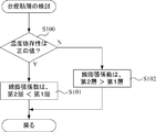
工程S10の詳細は、図7に示される。先ず、工程S100において、工程S7で決定された第2材料の共振周波数の温度依存性(工程S5にて取得)が、正の値か否かが判断される。例えば、図2A又は図2Bに示される場合であれば、SECCが第2材料として決定されている。台座がSECCから構成された場合、共振周波数の温度依存性は負(シミュレーションで-0.162[Hz/℃]、実測で-0.323[Hz/℃])であるため、工程S110の判断は否定される(S100:N)。この場合、工程S102が実行される。一方、共振周波数の温度依存性が正の値であれば、工程S110の判断は肯定される(S100:Y)。この場合、工程S101が実行される。
工程S101では、台座220の第2層222の材料として、第1層221の材料よりも線膨張係数が小さい材料が選択される。これによって、台座220全体での実質的な線膨張係数を下げることができ、共振周波数の温度依存性を0に近づけることができる。例えば、SUS304が第1層221の材料として決定されている場合であれば、SUS304よりも線膨張係数の小さな材料である、高機能バネ鋼やSUS430が、第2層222の材料として決定される(図5参照)。その後、台座の積層構造の検討は終了し、工程S11に移行する。
工程S102では、台座220の第2層222の材料として、第1層221の材料よりも線膨張係数が大きい材料が選択される。これによって、台座220全体での実質的な線膨張係数を上げることができ、共振周波数の温度依存性を0に近づけることができる。例えば、SECCが第1層221の材料として決定されている場合であれば、SECCよりも線膨張係数の大きな材料である、高機能バネ鋼やSUS304が、第2層222の材料として決定される。その後、台座の積層構造の検討は終了し、工程S11に移行する。
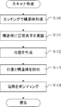
図6の工程S11において、光スキャナが作成される。ここで、工程S9の判断が肯定(S9:Y)の場合は、単一層からなる台座120を備える光スキャナ100が形成される。一方、工程S9の判断が否定(S9:N)の場合は、第1層221及び第2層222を有する台座220を備える光スキャナ200が形成される。なお、工程S11の詳細は、図8に示される。
先ず、工程S110において、所定の除去加工によって、構造体が形成される。本実施形態では、除去加工の一例として、ウェットエッチングが採用される。構造体を構成する金属板(例えば、SUS430)が、構造体の外形と等しい大きさに分割される。そして、分割された金属板の、ミラー部分、捩れ梁部分、本体部分に対応する位置に、マスキングのためのレジスト膜が形成される。その後、ウェットエッチングによって構造体の外形が形成された後に、レジスト膜が除去される。なお、構造体の外形に比して十分大きな金属板に複数の構造体の外形が形成された後に、個々の構造体に分割される多数個取りが実行されても差し支えない。または、ウェットエッチングでなく、プレス加工などの機械的な加工によって構造体が形成されても差し支えない。
次に、工程S111において、予め圧電素子の両面に電極層を備えたバルクの圧電材料が、構造体に実装される。この実装は、例えば、エポキシ系、アクリル系、シリコン系等の合成樹脂材料に金属フィラーなどの導電材を含有する導電性接着剤を用いて行われる。具体的には、構造体の本体部分に塗布された導電性接着剤の上に、バルクの圧電材料が設置される。圧電材料の設置後、100~200℃の雰囲気に保たれた加熱炉内に構造体が30~60分間装入されることによって、導電性接着剤が硬化する。以上で、圧電素子の実装が完了する。
次に、工程S112において、台座が作成される。台座の外形は、構造体の場合と同様に、台座の構成材料となる金属板に対して、エッチングやプレスなどの除去加工を施すことで得られる。なお、台座が第1層と第2層との積層構造の場合、第1層を構成するための金属板と、第2層を構成するための金属板とに対して、それぞれ除去加工が施される。なお、第1層及び第2層の厚みは、対応する厚みを有する金属板を加工することで、自動的に設定される。その後、第1層と第2層とが、接着や溶着などによって固定される。
次に、工程S113において、台座と構造体とが固定される。この固定は、例えば、レーザ溶接などによって、構造体の被固定部と台座とが溶着されることで行われる。ただし、熱硬化接着剤を利用した接着など、他の固定方法によって、構造体と台座とが固定されても差し支えない。
そして、工程S114において、圧電素子と構造体とに対して、ワイヤボンディングによって信号線が接続される。この信号線は、非図示の交流電源に接続される。構造体と圧電素子とは導電性接着剤によって接着されているので、この信号線を介して圧電素子と構造体との間に電圧が印加される。以上で、光スキャナの製造工程が終了する。
本開示は、今までに述べた実施形態に限定されることは無く、その趣旨を逸脱しない範囲において種々の変形・変更が可能である。以下にその一例を述べる。
前記した光スキャナ200において、台座220は、第1層221と第2層222とを有する。しかし、この実施例は、台座が3層以上の積層構造を有する構成を排除するものではない。台座が3層以上の積層構造で形成される場合、前記したように第1層及び第2層の材料が決定された上で、第3層以降の材料が決定されればよい。
前記した光スキャナ200において、第2層222の材料は、構成材料の種類、より具体的には構成材料の線膨張係数を変数として、共振周波数の温度依存性を低減するものに決定された。しかし、共振周波数の温度依存性を低減するために、第2層222の構造を決定する他の変数がさらに導入されても差し支えない。例えば、図9に示されるように、第2層222の厚みが変化すると、共振周波数の温度依存性も変化する。なお、図9に示される例は、構造体210がSUS430で、台座220の第1層221がSECCで、第2層222がSUS304で、それぞれ構成される。また、構造体210の厚みは100μmに、第1層221の厚みは2000μmに、それぞれ設定される。図9から明らかに、第2層222が厚くなるに従って、共振周波数の温度依存性が上昇する。即ち、例えば図7に示される工程S101又は工程S102の後で、第2層222の厚みを決定する工程が実行されても差し支えない。これによって、線膨張係数という変数に加えて、台座の厚みという変数を用いて、共振周波数の温度依存性の絶対値がさらに小さくなるように、台座の構造を決定することが可能になる。
前記した実施形態において、構造体及び台座は金属で構成される。しかし、本開示は、構造体と台座との線膨張係数を異ならせることで、共振周波数の温度依存性を緩和することに特徴がある。そのため、台座や構造体が例えばシリコンなどの非金属で構成されても、本開示の範囲に含まれる。同様に、構造体や台座の形状も、前記した実施例には限定されない。ミラー部分と捩れ梁部分と本体部分を有する平板状の構造体が、台座に対して固定されるタイプの光スキャナは、全て本発明の範囲に含まれる。また、前記した実施形態では、駆動部として圧電素子が利用される。しかし、磁石とコイルパターンとの組み合わせによる電磁駆動方式や、極板間に働く静電気力による静電駆動方式など、他の駆動方式を採用した光スキャナであっても、本開示の範囲に含まれる。
100,200 光スキャナ
110,210 構造体
111,211 ミラー部分
112,212 捩れ梁分
113,213 本体部分
113a,213a 被固定部分
113b,213b 節連結部分
114,214 圧電素子
120,220 台座
121,221 第1層
222 第2層
110,210 構造体
111,211 ミラー部分
112,212 捩れ梁分
113,213 本体部分
113a,213a 被固定部分
113b,213b 節連結部分
114,214 圧電素子
120,220 台座
121,221 第1層
222 第2層
Claims (9)
- 光を反射する反射面を含み、第1軸線を中心として揺動可能に構成されるミラー部分と、
前記ミラー部分の両側に連結され、前記第1軸線に平行に前記ミラー部分から延出する一対の捩れ梁部分と、
前記一対の捩れ梁部分の前記ミラー部分反対側の端部に連結され、前記第1軸線に交差する方向に延出する本体部分と、
を有し、第1材料によって構成される平板状の構造体と、
少なくとも前記構造体に設けられ、前記ミラー部分を所定の共振周波数にて前記第1軸線回りに揺動可能に構成される駆動部と、
第2材料によって構成され、前記構造体が固定される台座とを備え、
前記構造体は、前記本体部分の一部であって前記一対の捩れ梁部分及び前記ミラー部分を挟んで対向する一対の被固定部分において、少なくとも前記台座に固定され、
前記第2材料の線膨張係数は、前記第1材料の線膨張係数よりも大きく、且つ、前記共振周波数の温度依存性の絶対値が、前記台座が前記第1材料によって構成された場合の前記共振周波数の温度依存性の絶対値よりも小さくなる値に設定される、
ことを特徴とする光スキャナ。 - 前記台座は、
前記第2材料によって構成される第1層と、
前記第1層と前記構造体との間に設けられ、前記第2材料とは異なる線膨張係数を有する第3材料によって構成される第2層とを有し、
前記第2層は、前記構造体の前記被固定部分に固定され、
前記第1層は、前記第2層に固定される、
請求項1に記載の光スキャナ。 - 前記第2層は、前記第1層よりも積層方向における厚みが薄くなるように構成される、
請求項2に記載の光スキャナ。 - 前記第1材料及び前記第2材料は、金属である、
請求項1の何れか1項に記載の光スキャナ。 - 前記駆動部は、前記本体部分に設けられ、前記本体部分に板波を励起することで、前記本体部分及び前記一対の捩れ梁部分を介して前記ミラー部分を前記第1軸線回りに揺動させることが可能な圧電素子である、
請求項4に記載の光スキャナ。 - 光スキャナの製造方法であって、
光を反射する反射面を含み、第1軸線を中心として揺動可能に構成されるミラー部分と、前記ミラー部分の両側に連結され、前記第1軸線に平行に前記ミラー部分から延出する一対の捩れ梁部分と、前記一対の捩れ梁部分の前記ミラー部分反対側の端部に連結され、前記第1軸線に交差する方向に延出する本体部分とを有する構造体を構成する第1材料の線膨張係数よりも大きい値であって、互いに異なる線膨張係数の値を有する複数の材料を含む母集団から、前記構造体が固定される台座を構成する前記第2材料としての候補となる材料である第2材料候補を決定する候補決定工程と、
前記第2材料候補を前記第2材料として用いた場合における、前記光スキャナの共振周波数の温度依存性を決定する依存性決定工程と、
前記依存性決定工程によって前記温度依存性が決定された2つ以上の前記第2材料候補の中から、前記温度依存性の絶対値が最小となった前記第2材料候補を、前記第2材料として決定する第2材料決定工程と、
前記第2材料決定工程によって決定された前記第2材料を用いて、前記光スキャナを作成する作成工程と、
を有することを特徴とする光スキャナの製造方法。 - 前記2つ以上の前記第2材料候補の線膨張係数を取得する取得工程と、
前記2つ以上の前記第2材料候補の線膨張係数の値と、前記依存性決定工程によって決定された前記2つ以上の第2材料候補における前記温度依存性との相関関係を決定する関係決定工程をさらに備え、
前記第2材料決定工程は、前記関係決定工程によって決定された前記相関関係に基づいて、前記2つ以上の前記第2材料候補に加えて、前記母集団の中から前記温度依存性の絶対値が最小に近い値に対応する線膨張係数を有する材料を、前記第2材料として決定する、
請求項6に記載の光スキャナの製造方法。 - 前記第2材料決定工程によって決定された前記第2材料における前記温度依存性が、所定の範囲内に収まるか否かを判断する判断工程と、
前記判断工程において前記温度依存性が所定の範囲内に収まらないと判断された場合に、前記母集団の中から、前記台座の前記第2材料によって構成される第1層と前記構造体との間に設けられる第2層を構成する第3材料として用いる材料を決定する第3材料決定工程とをさらに有し、
前記作成工程は、前記判断工程において前記温度依存性が所定の範囲内に収まらないと判断された場合に、前記第2材料を前記台座の前記第1層とし、前記第3材料を前記第2層とする前記台座を用いて、前記光スキャナを製造する、
請求項6に記載の光スキャナの製造方法。 - 前記第3材料決定工程は、
前記温度依存性が負の値の場合、前記第2材料よりも大きな線膨張係数を有する材料を前記第3材料として決定し、
前記温度依存性が正の値の場合、前記第2材料よりも小さな線膨張係数を有する材料を前記第3材料として決定する、請求項8に記載の光スキャナの製造方法。
Applications Claiming Priority (2)
| Application Number | Priority Date | Filing Date | Title |
|---|---|---|---|
| JP2011-077585 | 2011-03-31 | ||
| JP2011077585A JP5310769B2 (ja) | 2011-03-31 | 2011-03-31 | 光スキャナ |
Publications (1)
| Publication Number | Publication Date |
|---|---|
| WO2012133505A1 true WO2012133505A1 (ja) | 2012-10-04 |
Family
ID=46931214
Family Applications (1)
| Application Number | Title | Priority Date | Filing Date |
|---|---|---|---|
| PCT/JP2012/058090 Ceased WO2012133505A1 (ja) | 2011-03-31 | 2012-03-28 | 光スキャナ及び光スキャナの製造方法 |
Country Status (2)
| Country | Link |
|---|---|
| JP (1) | JP5310769B2 (ja) |
| WO (1) | WO2012133505A1 (ja) |
Cited By (1)
| Publication number | Priority date | Publication date | Assignee | Title |
|---|---|---|---|---|
| IT201600079604A1 (it) * | 2016-07-28 | 2018-01-28 | St Microelectronics Srl | Struttura oscillante con attuazione piezoelettrica, sistema e metodo di fabbricazione |
Families Citing this family (2)
| Publication number | Priority date | Publication date | Assignee | Title |
|---|---|---|---|---|
| JP6024269B2 (ja) * | 2011-09-20 | 2016-11-16 | 株式会社デンソー | 光走査装置 |
| JPWO2023021777A1 (ja) * | 2021-08-19 | 2023-02-23 |
Citations (3)
| Publication number | Priority date | Publication date | Assignee | Title |
|---|---|---|---|---|
| JP2001523350A (ja) * | 1994-10-26 | 2001-11-20 | ボード オブ リージェンツ オブ ザ ユニバーシティ オブ ワシントン | 2軸スキャニングシステム用の小型光学式スキャナー |
| JP2002321195A (ja) * | 2001-04-20 | 2002-11-05 | Olympus Optical Co Ltd | 振動体およびその製造方法 |
| WO2008041585A1 (fr) * | 2006-09-27 | 2008-04-10 | National Institute Of Advanced Industrial Science And Technology | Dispositif de balayage optique |
Family Cites Families (1)
| Publication number | Priority date | Publication date | Assignee | Title |
|---|---|---|---|---|
| JP5267370B2 (ja) * | 2009-07-23 | 2013-08-21 | ブラザー工業株式会社 | 光スキャナ |
-
2011
- 2011-03-31 JP JP2011077585A patent/JP5310769B2/ja not_active Expired - Fee Related
-
2012
- 2012-03-28 WO PCT/JP2012/058090 patent/WO2012133505A1/ja not_active Ceased
Patent Citations (3)
| Publication number | Priority date | Publication date | Assignee | Title |
|---|---|---|---|---|
| JP2001523350A (ja) * | 1994-10-26 | 2001-11-20 | ボード オブ リージェンツ オブ ザ ユニバーシティ オブ ワシントン | 2軸スキャニングシステム用の小型光学式スキャナー |
| JP2002321195A (ja) * | 2001-04-20 | 2002-11-05 | Olympus Optical Co Ltd | 振動体およびその製造方法 |
| WO2008041585A1 (fr) * | 2006-09-27 | 2008-04-10 | National Institute Of Advanced Industrial Science And Technology | Dispositif de balayage optique |
Cited By (3)
| Publication number | Priority date | Publication date | Assignee | Title |
|---|---|---|---|---|
| IT201600079604A1 (it) * | 2016-07-28 | 2018-01-28 | St Microelectronics Srl | Struttura oscillante con attuazione piezoelettrica, sistema e metodo di fabbricazione |
| EP3276391A1 (en) * | 2016-07-28 | 2018-01-31 | STMicroelectronics S.r.l. | Oscillating structure with piezoelectric actuation, system and manufacturing method |
| US10365475B2 (en) | 2016-07-28 | 2019-07-30 | Stmicroelectronics S.R.L. | Oscillating structure with piezoelectric actuation, system and manufacturing method |
Also Published As
| Publication number | Publication date |
|---|---|
| JP5310769B2 (ja) | 2013-10-09 |
| JP2012212022A (ja) | 2012-11-01 |
Similar Documents
| Publication | Publication Date | Title |
|---|---|---|
| JP5229704B2 (ja) | 光走査装置 | |
| JP5476589B2 (ja) | 光走査装置 | |
| JP5457442B2 (ja) | 圧電素子の共振周波数の調整方法 | |
| JP5157499B2 (ja) | 光スキャナ | |
| KR101343314B1 (ko) | 광빔 주사장치 | |
| JP2006518094A (ja) | 造形能動材料から構成された曲げアクチュエータ及びセンサ、並びにそれらの製造方法 | |
| CN104521130B (zh) | 压电发电装置 | |
| JP4982814B2 (ja) | 光ビーム走査装置 | |
| US10276775B2 (en) | Vibration device | |
| JPWO2012073656A1 (ja) | 圧電発電装置及びその製造方法 | |
| JP6292486B2 (ja) | Mems素子 | |
| JP4766353B2 (ja) | 光ビーム走査装置 | |
| JP5310769B2 (ja) | 光スキャナ | |
| JP4898551B2 (ja) | 圧電アクチュエータおよびそれを用いた走査型プローブ顕微鏡 | |
| JP5539628B2 (ja) | 光走査用マイクロミラーデバイス、光走査装置、画像形成装置、表示装置および入力装置 | |
| JP5296424B2 (ja) | 光走査装置、画像形成装置、表示装置及び入力装置 | |
| US20070139750A1 (en) | Oscillating mirror having a plurality of eigenmodes | |
| WO2023021777A1 (ja) | 駆動素子 | |
| JP5561959B2 (ja) | 静電振動子及び電子機器 | |
| KR20140017477A (ko) | 광주사 장치 | |
| JP2013064843A (ja) | 光スキャナ | |
| JP2013114015A (ja) | 光スキャナ | |
| JP5816008B2 (ja) | バイモルフ光学素子 | |
| JP2011158342A (ja) | 圧力センサー | |
| JP7105116B2 (ja) | 超音波センサ |
Legal Events
| Date | Code | Title | Description |
|---|---|---|---|
| 121 | Ep: the epo has been informed by wipo that ep was designated in this application |
Ref document number: 12763734 Country of ref document: EP Kind code of ref document: A1 |
|
| NENP | Non-entry into the national phase |
Ref country code: DE |
|
| 122 | Ep: pct application non-entry in european phase |
Ref document number: 12763734 Country of ref document: EP Kind code of ref document: A1 |