WO2012133307A1 - 建設機械 - Google Patents
建設機械 Download PDFInfo
- Publication number
- WO2012133307A1 WO2012133307A1 PCT/JP2012/057751 JP2012057751W WO2012133307A1 WO 2012133307 A1 WO2012133307 A1 WO 2012133307A1 JP 2012057751 W JP2012057751 W JP 2012057751W WO 2012133307 A1 WO2012133307 A1 WO 2012133307A1
- Authority
- WO
- WIPO (PCT)
- Prior art keywords
- oil
- engine
- generator motor
- hydraulic pump
- construction machine
- Prior art date
- Legal status (The legal status is an assumption and is not a legal conclusion. Google has not performed a legal analysis and makes no representation as to the accuracy of the status listed.)
- Ceased
Links
Images





Classifications
-
- E—FIXED CONSTRUCTIONS
- E02—HYDRAULIC ENGINEERING; FOUNDATIONS; SOIL SHIFTING
- E02F—DREDGING; SOIL-SHIFTING
- E02F9/00—Component parts of dredgers or soil-shifting machines, not restricted to one of the kinds covered by groups E02F3/00 - E02F7/00
- E02F9/20—Drives; Control devices
- E02F9/22—Hydraulic or pneumatic drives
-
- E—FIXED CONSTRUCTIONS
- E02—HYDRAULIC ENGINEERING; FOUNDATIONS; SOIL SHIFTING
- E02F—DREDGING; SOIL-SHIFTING
- E02F9/00—Component parts of dredgers or soil-shifting machines, not restricted to one of the kinds covered by groups E02F3/00 - E02F7/00
- E02F9/08—Superstructures; Supports for superstructures
- E02F9/0858—Arrangement of component parts installed on superstructures not otherwise provided for, e.g. electric components, fenders, air-conditioning units
- E02F9/0866—Engine compartment, e.g. heat exchangers, exhaust filters, cooling devices, silencers, mufflers, position of hydraulic pumps in the engine compartment
-
- E—FIXED CONSTRUCTIONS
- E02—HYDRAULIC ENGINEERING; FOUNDATIONS; SOIL SHIFTING
- E02F—DREDGING; SOIL-SHIFTING
- E02F9/00—Component parts of dredgers or soil-shifting machines, not restricted to one of the kinds covered by groups E02F3/00 - E02F7/00
- E02F9/08—Superstructures; Supports for superstructures
- E02F9/0858—Arrangement of component parts installed on superstructures not otherwise provided for, e.g. electric components, fenders, air-conditioning units
- E02F9/0891—Lids or bonnets or doors or details thereof
-
- E—FIXED CONSTRUCTIONS
- E02—HYDRAULIC ENGINEERING; FOUNDATIONS; SOIL SHIFTING
- E02F—DREDGING; SOIL-SHIFTING
- E02F9/00—Component parts of dredgers or soil-shifting machines, not restricted to one of the kinds covered by groups E02F3/00 - E02F7/00
- E02F9/26—Indicating devices
-
- F—MECHANICAL ENGINEERING; LIGHTING; HEATING; WEAPONS; BLASTING
- F01—MACHINES OR ENGINES IN GENERAL; ENGINE PLANTS IN GENERAL; STEAM ENGINES
- F01M—LUBRICATING OF MACHINES OR ENGINES IN GENERAL; LUBRICATING INTERNAL COMBUSTION ENGINES; CRANKCASE VENTILATING
- F01M1/00—Pressure lubrication
- F01M1/18—Indicating or safety devices
-
- G—PHYSICS
- G01—MEASURING; TESTING
- G01F—MEASURING VOLUME, VOLUME FLOW, MASS FLOW OR LIQUID LEVEL; METERING BY VOLUME
- G01F23/00—Indicating or measuring liquid level or level of fluent solid material, e.g. indicating in terms of volume or indicating by means of an alarm
- G01F23/04—Indicating or measuring liquid level or level of fluent solid material, e.g. indicating in terms of volume or indicating by means of an alarm by dip members, e.g. dip-sticks
-
- H—ELECTRICITY
- H02—GENERATION; CONVERSION OR DISTRIBUTION OF ELECTRIC POWER
- H02K—DYNAMO-ELECTRIC MACHINES
- H02K9/00—Arrangements for cooling or ventilating
- H02K9/19—Arrangements for cooling or ventilating for machines with closed casing and closed-circuit cooling using a liquid cooling medium, e.g. oil
-
- F—MECHANICAL ENGINEERING; LIGHTING; HEATING; WEAPONS; BLASTING
- F01—MACHINES OR ENGINES IN GENERAL; ENGINE PLANTS IN GENERAL; STEAM ENGINES
- F01M—LUBRICATING OF MACHINES OR ENGINES IN GENERAL; LUBRICATING INTERNAL COMBUSTION ENGINES; CRANKCASE VENTILATING
- F01M11/00—Component parts, details or accessories, not provided for in, or of interest apart from, groups F01M1/00 - F01M9/00
- F01M11/0004—Oilsumps
-
- F—MECHANICAL ENGINEERING; LIGHTING; HEATING; WEAPONS; BLASTING
- F01—MACHINES OR ENGINES IN GENERAL; ENGINE PLANTS IN GENERAL; STEAM ENGINES
- F01M—LUBRICATING OF MACHINES OR ENGINES IN GENERAL; LUBRICATING INTERNAL COMBUSTION ENGINES; CRANKCASE VENTILATING
- F01M11/00—Component parts, details or accessories, not provided for in, or of interest apart from, groups F01M1/00 - F01M9/00
- F01M11/10—Indicating devices; Other safety devices
- F01M11/12—Indicating devices; Other safety devices concerning lubricant level
-
- H—ELECTRICITY
- H02—GENERATION; CONVERSION OR DISTRIBUTION OF ELECTRIC POWER
- H02K—DYNAMO-ELECTRIC MACHINES
- H02K7/00—Arrangements for handling mechanical energy structurally associated with dynamo-electric machines, e.g. structural association with mechanical driving motors or auxiliary dynamo-electric machines
- H02K7/14—Structural association with mechanical loads, e.g. with hand-held machine tools or fans
Definitions
- the present invention relates to a hybrid construction machine equipped with an engine, a hydraulic pump and a generator motor.
- a so-called hybrid construction machine in which a generator motor is mounted between an engine and a hydraulic pump has been developed.
- the generator motor mounted on such a hybrid construction machine is connected to the output shaft of the engine and the input shaft of the hydraulic pump, and generates power by the driving force of the engine.
- the electric energy generated by the power generation by the generator motor is stored in a power storage device such as a capacitor.
- the generator motor is driven by the stored electric energy, and the engine To help output.
- Patent Document 1 includes an oil sump portion that stores cooling oil in a housing, and a generator motor that can efficiently cool oil by uniformly injecting oil to a plurality of coil end portions. The configuration is disclosed.
- Patent Document 2 discloses a configuration of a generator motor incorporated between an engine and a hydraulic pump.
- JP 2007-6554 A published on January 11, 2007
- JP 2003-235208 A released on August 22, 2003
- the conventional construction machine has the following problems.
- the generator motor disclosed in Patent Document 1 is provided with an oil test tube that communicates with the oil reservoir portion in order to check the amount of oil stored in the oil reservoir portion provided in the housing.
- the generator motor motor in the structure which has arrange
- An oil inspection port of the oil inspection pipe of the generator motor is provided on the hood side above the hydraulic pump so that the inspection can be performed.
- the hydraulic pump when viewed from the hood side of the vehicle body side, the hydraulic pump has a diameter of a circular member that covers the flange of the generator motor on the surface of the generator motor.
- the hood side of the hydraulic pump has a cross-sectional area corresponding to the hydraulic pump main body. For this reason, the cross-sectional area of the hydraulic pump gradually decreases as it approaches the hood side.
- the oil test tube is arranged under such conditions, the oil test tube is provided along the shape of the hydraulic pump, and is therefore arranged obliquely so as to approach the rotation axis of the hydraulic pump as it approaches the hood side.
- An object of the present invention is to provide a construction machine capable of improving workability during maintenance in a construction machine in which a generator motor is mounted between an engine and a hydraulic pump.
- the construction machine includes an engine, a hydraulic pump, a generator motor, and an oil inspection pipe.
- the hydraulic pump is driven by the driving force of the engine.
- the generator motor is provided between the engine and the hydraulic pump, and includes a rotary shaft connected to the output shaft of the engine and an input shaft of the hydraulic pump, and oil provided in a lower portion of a storage space formed in the housing. And a reservoir.
- the oil inspection pipe has a connection part provided at a position communicating with the oil sump part in order to check the amount of oil stored in the oil sump part of the generator motor, and an oil inspection port disposed above the generator motor. And having.
- the amount of oil stored in an oil reservoir provided in the generator / motor housing is measured.
- the oil inspection port of the oil inspection pipe for inspection is provided above the generator motor.
- the generator motor is also provided above the generator motor so that the engine motor can be inspected from the upper surface of the vehicle by opening the engine hood, like other inspection objects such as the engine. Yes.
- a construction machine according to a second invention is the construction machine according to the first invention, further comprising an openable and closable engine hood that covers an upper space of an engine room that houses the engine, the hydraulic pump, and the generator motor. .
- the oil inspection port of the oil inspection pipe is provided in a space exposed by opening the engine hood.
- a construction machine according to a third invention is the construction machine according to the first or second invention, and further includes an engine oil inspection pipe for checking the oil amount of the engine.
- the oil inspection port of the oil inspection tube is provided on the same side as the oil inspection port of the engine oil inspection tube.
- a construction machine according to a fourth invention is the construction machine according to any one of the first to third inventions, wherein the housing is fixed to the engine housing side and the hydraulic pump side. And a second housing.
- the connection part is provided in the first housing.
- the connecting part of the oil detection pipe of the generator motor arranged between the engine and the hydraulic pump is provided on the first housing side fixed to the engine side.
- a construction machine according to a fifth invention is the construction machine according to any one of the first to fourth inventions, wherein the oil inspection pipe can also be used as an oil supply pipe for supplying oil to the generator motor. It is.
- the above-described oil inspection tube is also used as an oil supply tube that supplies oil to the oil reservoir.
- Oil can be supplied to the reservoir.
- the generator motor and the oil inspection pipe and the oil supply pipe are separately provided, the number of parts can be reduced, the configuration can be simplified, and the space in the engine room can be effectively utilized. it can.
- a construction machine according to a sixth invention is the construction machine according to any one of the first to fifth inventions, wherein the oil inspection pipe is bent so as to avoid the muffler mounted on the engine. Has a part.
- a bent part (bent part) for avoiding the muffler mounted on the engine is provided in a part of the oil inspection pipe.
- a muffler with a large calorific value mounted on the engine may be disposed immediately above the generator motor.
- the bent portion is provided so that the heat of the muffler does not adversely affect the oil inspection pipe.
- an oil test tube can be guide
- a construction machine according to a seventh invention is a construction machine according to any one of the first to sixth inventions, and is a hydraulic excavator.
- FIG. 1 is an overall perspective view showing a configuration of a hydraulic excavator according to an embodiment of the present invention.
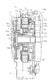
- the perspective view which shows the structure of the engine, generator motor, and hydraulic pump which are mounted in the hydraulic excavator of FIG. Sectional drawing which shows the structure of the generator motor contained in FIG.
- the disassembled perspective view which shows the structure of the generator motor contained in FIG.
- the perspective view of the generator motor contained in FIG. The perspective view of the generator motor contained in FIG.
- a hybrid hydraulic excavator (construction machine) 51 will be described below with reference to FIGS. (Hydraulic excavator 51)
- the hybrid hydraulic excavator 51 includes a lower traveling body 52, a swivel base 53, a work implement 54, a counterweight 55, an equipment room 56, a vehicle body portion 57, and the like.
- the cab 58 is provided.
- the excavator 51 includes the engine 2 as a drive source.
- the generator motor 1 and the hydraulic pump 4 are connected in series to the output shaft of the engine 2 and are driven by the engine 2 respectively.
- the lower traveling body 52 causes the excavator 51 to move forward and backward by rotating the crawler belt P wound around the left and right ends in the traveling direction.
- the lower traveling body 52 has a swivel base 53 mounted on the upper surface.
- the turntable 53 can turn in any direction with respect to the lower traveling body 52.
- the swivel base 53 has a work machine 54, a counterweight 55, an equipment chamber 56, a vehicle body 57, and a cab 58 mounted on the upper surface.
- the swivel base 53 is rotated by a turning electric motor driven by power supply from the generator motor 1 or the battery. Note that the swing electric motor generates power by regeneration when the swivel base 53 is decelerated, and the electric energy obtained by the power generation is stored in the capacitor.
- the work implement 54 is configured to include a boom 61, an arm 62 attached to the tip of the boom 61, and a bucket 63 attached to the tip of the arm 62.
- the working machine 54 moves the boom 61, the arm 62, the bucket 63, and the like up and down by the hydraulic cylinders 61a, 62a, 63a and the like included in a hydraulic circuit (not shown), and the earth and sand and gravel on the site of the civil engineering work.
- the counterweight 55 is made of, for example, scrap iron or concrete in a box formed by assembling steel plates and hardened, and is provided behind the swivel base 53 to balance the vehicle body during mining. ing.
- the equipment room 56 is disposed at a position adjacent to the counterweight 55, and an engine room 60 that houses the engine 2, the generator / motor 1, the hydraulic pump 4, etc. (see FIG. 2). have.
- the engine room 60 has an inspection upper opening 60a (see FIG. 7) covered with an engine hood 64 that can be opened and closed.
- the configuration around the generator motor 1 installed in the engine room 60 will be described in detail later.
- the equipment room 56 is surrounded by a hydraulic oil tank (not shown), a partition member provided between the engine room 60 and the cab 58, an open / close cover provided on the left and right rear sides of the vehicle, a counterweight 55, an engine hood 64, and the like. Space.
- the engine 2 the generator motor 1, and the hydraulic pump 4 are juxtaposed along the counterweight 55.
- the vehicle body portion 57 is disposed behind the work implement 54 and houses a fuel tank, a hydraulic oil tank, an operation valve, and the like (not shown).
- the cab 58 has an indoor space where an operator of the excavator 51 can get on and off.
- the cab 58 is disposed on the left front side on the swivel 53 so that the front end of the work machine 54 can be seen. ing.
- the generator motor 1 of this embodiment is mounted on a hybrid hydraulic excavator 51 including an engine 2, a cooling fan 3, a hydraulic pump 4, a muffler 5, and the like.
- the generator motor 1 is disposed between the engine 2 and the hydraulic pump 4.
- the generator motor 1 has a rotary shaft 19 (see FIG. 3) connected directly or indirectly to the output shaft of the engine 2 and the input shaft of the hydraulic pump 4. Electricity is generated by the rotational driving force.
- the generator motor 1 is connected to a capacitor via an inverter. When the rotational speed of the engine 2 increases (the hydraulic excavator 51 accelerates), the generator motor 1 is used as an electric motor by the electric energy stored in the capacitor as needed, and the rotation of the engine 2 Assist.
- the generator motor 1 When the engine 2 is in an idling state, the generator motor 1 receives the rotational driving force of the engine 2 to generate electric power, and electric energy generated by the electric power generation is stored in the capacitor. Moreover, in this embodiment, the engine 2, the generator motor 1, and the hydraulic pump 4 are arrange
- the generator motor 1 is a three-phase 12-pole SR (switched reluctance) motor, and has an oil reservoir V at the bottom. 3 and 4, the generator motor 1 includes a stator 10, a first housing 11, a flywheel 12, a coupling 13, a rotor 14, a second housing 15, a flange ( (Flange part) 16 and a rotating shaft 19 are provided.
- the stator 10 is provided in a storage space formed in the first and second housings 11 and 15 that constitute the outer shell of the generator motor 1.
- the stator 10 includes an annular stator core 20, an insulator 21, a coil 23, and the like.
- the stator core 20 is configured by laminating a plurality of steel plates including an annular yoke portion and a portion of a stator tooth that is arranged along the circumferential direction and protrudes radially inward from the yoke portion. Yes.
- a stator core 20 including a total of 36 protrusions is used to form a three-phase 12-pole SR motor. After the insulator 21 is attached to each of the plurality of protrusions, the coil 23 is wound.
- the first housing 11 is a cast iron member, and as shown in FIG. 3, is joined to the second housing 15 to form a storage space for storing the stator 10, the rotor 14, and the like.
- a storage space for storing the stator 10, the rotor 14, and the like.
- an oil reservoir V for promoting lubrication of the rotary shaft 19 and the bearing portion 18 and storing cooling oil for cooling the heat generating portion (coil 23 and the like) of the stator 10.
- an oil inspection pipe oil supply pipe for checking the amount of oil stored in the oil reservoir V and supplying oil to the oil reservoir V is provided at the lower end of the first housing 11. And 30) are connected.
- the configuration of the oil inspection pipe 30 will be described in detail later.
- the cooling oil stored in the oil reservoirs V in the first and second housings 11 and 15 is circulated by a circulation pump (not shown) and is provided at the lower part of the second housing 15. After being cooled via the cooling device (for example, oil cooler 15d (see FIG. 4)), it is returned to the space in the first and second housings 11 and 15 again.
- a circulation pump not shown
- the cooling device for example, oil cooler 15d (see FIG. 4)
- the flywheel 12 is provided on the output shaft side of the engine 2 in the first and second housings 11 and 15, is connected to the rotor 14 via the coupling 13, and is in the first and second housings 11 and 15. Rotate at.
- the coupling 13 is a substantially annular member and is bolted to the flywheel 12. Further, as shown in FIG. 3, the coupling 13 has a spline formed on the inner diameter side meshing with an external spline 19 a formed on the outer diameter side of the rotary shaft 19. As a result, the flywheel 12 and the coupling 13 rotate together with the rotor 14 around the rotation shaft 19.
- the rotor 14 is a rotating member that rotates about a rotating shaft 19, and is an inner peripheral side of the annular stator 10 in the storage space in the first and second housings 11 and 15. Inserted into the space.
- the rotor 14 has a holder 14b to which a rotor yoke 14a is attached on the outer peripheral surface.
- the rotor yoke 14a is a structure in which a plurality of steel plates (electromagnetic steel plates) are laminated, and is bolted to the outer peripheral surface side of the holder 14b as shown in FIG. 3, and on the outer peripheral surface side of the annular main body, A plurality of inductors (not shown) provided at equal angular intervals in the circumferential direction are provided.
- the rotor yoke 14a is held so as to be sandwiched between aluminum blades 14c and 14c provided on the engine 2 side and the hydraulic pump 4 side, respectively.
- Through-holes opened outward in the radial direction are formed on the outer peripheral surfaces of the blades 14c, 14c.
- cooling oil is injected from the through hole to the coil 23 disposed radially outward.
- the rotor yoke 14a can be hold
- the holder 14 b is bolted to the outer peripheral portion of the rotating shaft 19 with the rotating shaft 19 inserted in the center hole.
- the holder 14b is a steel member having a substantially cylindrical shape, and has a structure in which an inner cylindrical portion and an outer cylindrical portion are combined, and the outer peripheral surface of the inner cylindrical portion and the outer cylinder are combined.
- a bearing portion 18 is attached to the inner peripheral surface of the portion, and a rotor yoke 14a is attached to the outer peripheral surface of the outer cylindrical portion.
- the rotating shaft 19 is a cylindrical member that serves as the rotation center of the rotor 14 and has a through hole that penetrates from one end portion to the other end portion in the axial direction.
- An external spline 19a fitted to the internal teeth of the coupling 13 and an internal spline 19b fitted to the input shaft on the hydraulic pump 4 side are formed at the end on the hydraulic pump 4 side, respectively.
- the rotary shaft 19 is fixed in a state where a half on the hydraulic pump 4 side in the axial direction is inserted into the inner peripheral surface side of the cylindrical portion inside the flange 16.
- the second housing 15 is a member made of cast iron, and is provided on the hydraulic pump 4 side in the generator motor 1, together with the first housing 11, the flywheel 12, the coupling 13, A storage space for storing the rotor 14, the stator 10, and the rotating shaft 19 is formed.
- the second housing 15 has an oil cooler 15d for cooling the cooling oil.
- a cooling oil pipe 15a is connected to the outlet of the oil cooler 15d for sending the cooling oil to the upper part of the first and second housings 11 and 15.
- a cooling water pipe 15 b that guides cooling water from the engine 2 side is connected to the lower portion of the second housing 15.
- an electric box 17 to which the wiring of the coil 23 wound around the protrusion of the stator core 20 is connected via the insulator 21 is attached to the shoulder portion of the second housing 15.
- the cooling oil stored in the oil sump V passes through a pipe (not shown), a filter (not shown), a circulation pump (for example, an electric pump), and the oil cooler 15d provided at the lower portion of the second housing 15. Supplied to the entrance.
- the cooling oil pipe 15 a connected to the outlet of the oil cooler 15 d is an upper part of the space formed in the first and second housings 11 and 15 for the cooling oil sucked up from the oil reservoir V. Is connected to the top of the two housings 15.
- the cooling water pipe 15b is connected to the engine 2, and the cooling water serving as a cooling medium in the oil cooler 15d provided at the lower portion of the generator motor 1 is transferred from the engine 2 to the oil cooler 15d. Supply.
- This cooling water is supplied to the engine 2 after being cooled by the radiator.
- the cooling water branched in the engine 2 passes through the cooling water pipe 15b and is supplied to the oil cooler 15d.
- the cooling water supplied from the inlet side of the oil cooler 15d into the oil cooler 15d exchanges heat with the cooling oil and then returns to the engine 2 from the outlet side through the cooling water return pipe 15c. After merging with the cooling water in the engine 2, it is returned to the radiator again and cooled by exchanging heat with air.
- the cooling water pipe 15b and the cooling water return pipe 15c are rubber pipes.
- the flange 16 is a disk-shaped member arranged coaxially with the rotary shaft 19, and the cooling oil sent to the upper part of the second housing 15 via the cooling oil pipe 15 a is desired.
- a cooling oil passage 16a that leads to this portion is formed inside.
- the flange 16 is fixed to the hydraulic pump 4 side of the second housing 15 by a plurality of bolts.
- the flange 16 has a substantially cylindrical bearing support portion 16e that protrudes in the axial direction from a substantially disk-shaped surface.
- the bearing support portion 16e supports the bearing portion 18 on the substantially cylindrical outer peripheral surface side.
- the cooling oil passage 16a allows the cooling oil flowing from the upper spaces in the first and second housings 11 and 15 to receive the bearing portion 18 and the spline (engagement) in which the rotor 14 and the rotary shaft 19 are in contact with the fixed member. Part)). Accordingly, a sufficient amount of lubricating oil (cooling oil) is always supplied to the bearing portion 18 and the spline (engagement portion). Further, the oil that moves through the cooling oil passage 16a in this way moves radially outward by the centrifugal force generated when the rotating member such as the rotor 14 rotates, and is supplied to the coil 23 on the hydraulic pump 4 side. It also functions as a cooling oil for cooling.
- the oil lubricates and cools the spline portion on the engine 2 side through the through hole in the rotary shaft 19. Thereafter, the oil moves radially outward by centrifugal force generated when the rotation side member such as the rotor 14 rotates, and is used for cooling the coil 23 provided on the engine 2 side.
- the generator motor 1 mounted on the hybrid hydraulic excavator 51 of the present embodiment includes an engine 2 out of the first and second housings 11 and 15 constituting the outer shell of the generator motor 1.
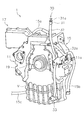
- the oil inspection pipe 30 is connected to the lower part of the first housing 11 fixed to the side.
- the oil test tube 30 is provided to check the amount of oil in the oil sump V formed in the first and second housings 11 and 15.
- the oil inspection pipe 30 is also used as an oil supply pipe for supplying oil into the oil reservoir V.
- the oil inspection tube 30 has an oil inspection port 31, a main body portion 32, and a connection portion 33, as shown in FIGS.
- the oil inspection pipe 30 is led to the upper opening 60a side of the engine room 60 exposed when the engine hood 64 is opened.
- the oil inspection port 31 is provided above the generator motor 1 via the main body portion 32 and the connection portion 33.
- the oil inspection port 31 allows the oil stored in the oil sump portion V formed in the first and second housings 11 and 15 to be appropriate by inserting and removing the oil inspection rod 31a inserted in the tip portion. Check whether the amount is stored.
- the oil inspection port 31 is provided above the generator motor 1, as shown in FIG. 7, the engine provided on the upper surface of the equipment chamber 56 of the swivel base 53 of the hybrid hydraulic excavator 51. It is disposed at a position where it can be easily accessed with the hood 64 opened.
- the oil amount in the generator motor 1 is also checked by the oil inspection rod 31a inserted into the oil inspection tube 30 at the same time. Can do. For this reason, workability at the time of inspection can be improved.
- the engine oil inspection pipe 2a and the oil inspection port 31 of the generator motor 1 are provided on the same side as in the present embodiment, for example, without being separately installed in the front and rear, left and right of the vehicle. Is preferred. Thereby, workability
- the main body portion 32 is a steel pipe member, and connects the connection portion 33 to the oil inspection port 31. Further, as shown in FIG. 6, the main body portion 32 has a bent portion 32 a that is bent in a direction in which the oil inspection port 31 is led to the engine 2 side in a side view of the generator motor 1.
- the bent portion 32a is provided in the vicinity of the central portion of the main body portion 32, and the main body portion 32 is bent toward the engine 2 with the support member 11a provided in the first housing 11 as a base point. Thereby, as shown in FIG. 2, it can be avoided that the oil inspection pipe 30 is provided in the vicinity of the muffler 5 provided in the vicinity immediately above the generator motor 1.
- the oil inspection tube 30 is not affected by the heat of the muffler 5.
- the oil inspection port 31 can be provided apart from the muffler 5, so that the operator is not affected by the heat of the muffler 5 at the time of inspection work such as checking the amount of oil or refilling oil.
- the connecting portion 33 is attached to the lower portion of the first housing 11 fixed to the engine 2 side of the generator motor 1 and communicates with an oil sump portion V formed in the generator motor 1.
- the hydraulic excavator 51 of the present embodiment is equipped with a generator motor 1 provided between an engine 2 and a hydraulic pump 4 and having an oil sump portion V formed therein.
- An oil inspection pipe 30 having a connection portion 33 communicating with the oil sump portion V of the motor 1 and an oil inspection port 31 disposed above the generator motor 1 is provided.
- the maintenance of the generator motor 1 is performed together with the maintenance of the engine 2 with the engine hood 64 opened on the upper surface of the equipment chamber 56 of the swivel 53 of the hybrid excavator 51.
- the workability in the maintenance work of the hybrid excavator 51 can be improved as compared with the conventional one.
- the cross-sectional area of the hydraulic pump 4 is larger (the generator motor 1 side) than the conventional configuration in which the oil detection port is provided on the hydraulic pump side via a mounting base or the like. It is possible to avoid the occurrence of a problem such that the portion) comes into contact with a part of the oil inspection tube 30 and is broken.
- connection part 33 of the oil test pipe 30 demonstrated and demonstrated the example provided in the 1st housing 11 fixed to the engine 2 side of the generator motor 1.
- FIG. the present invention is not limited to this.
- the connecting portion of the oil inspection pipe may be provided in the second housing on the hydraulic pump side. Even in this case, during maintenance of the engine, generator motor, etc., the engine and generator motor can be maintained together with the engine hood open on the upper surface of the swivel device room, improving workability. The same effect as described above can be obtained.
- the connecting part of the oil inspection pipe is provided in the first housing on the engine side as in the above embodiment. More preferred.
- the present invention can be similarly applied to other hybrid construction machines such as a wheel loader, a bulldozer, and a dump truck.
- the construction machine of the present invention has an effect that the workability in the maintenance work can be improved as compared with the conventional construction machine. Therefore, the construction machine is a hybrid type construction machine in which a generator motor is mounted between the engine and the hydraulic pump. Widely applicable.
Landscapes
- Engineering & Computer Science (AREA)
- General Engineering & Computer Science (AREA)
- Mining & Mineral Resources (AREA)
- Civil Engineering (AREA)
- Structural Engineering (AREA)
- Power Engineering (AREA)
- Mechanical Engineering (AREA)
- Physics & Mathematics (AREA)
- Fluid Mechanics (AREA)
- General Physics & Mathematics (AREA)
- Motor Or Generator Cooling System (AREA)
- Component Parts Of Construction Machinery (AREA)
- Connection Of Motors, Electrical Generators, Mechanical Devices, And The Like (AREA)
- Operation Control Of Excavators (AREA)
Abstract
Description
このようなハイブリッド型の建設機械に搭載された発電機モータは、エンジンの出力軸と油圧ポンプの入力軸とに接続されており、エンジンの駆動力によって発電を行う。そして、発電機モータでの発電により生じた電気エネルギーはキャパシタなどの蓄電装置に蓄えられ、建設機械が大きなエンジン出力を要する場合等に、蓄えられた電気エネルギーによって発電機モータが駆動されて、エンジンの出力を補助する。
すなわち、上記特許文献1に開示された発電機モータは、ハウジング内に設けられた油溜め部に貯留された油の量を点検するために、油溜め部に連通する検油管が設けられている。そして、このような発電機モータを、上記特許文献2のようにエンジンと油圧ポンプとの間に配置した構成では、点検者が地面に居る状態で車両側面に設けられたフードから発電機モータの点検を実施できるように、発電機モータの検油管の検油口が油圧ポンプの上のフード側に設けられている。
本発明の建設機械では、発電機モータについても、エンジン等の他の点検対象物と同様に、エンジンフードを開けて車両上面から点検できるように、検油口を発電機モータの上方に設けている。
これにより、エンジンの油量を点検する際に、同時に、発電機モータの油量も点検することができる。この結果、点検時における作業性を向上させることができる。
ここでは、エンジンと油圧ポンプとの間に配置された発電機モータの検油管の接続部を、エンジン側に固定された第1ハウジング側に設けている。
この結果、発電機モータや油圧ポンプ周辺のメンテナンス作業を実施する際の作業性を従来よりも向上させることができる。
ここでは、上述した検油管を、油溜め部に貯留された油の量を点検することに加えて、油溜め部に油を供給する給油管としても使用する。
ここで、発電機モータは、エンジンに隣接して配置されているため、発電機モータの真上にはエンジンに搭載された発熱量の大きいマフラーが配置されていることがある。
これにより、マフラーの熱が検油管に及ぶことを回避するとともに、マフラーの配置されていないスペースに余裕がある側へ検油管を導くことができる。
(油圧ショベル51)
本実施形態に係るハイブリッド型の油圧ショベル51は、図1に示すように、下部走行体52と、旋回台53と、作業機54と、カウンタウェイト55と、機器室56と、車体部57と、キャブ58と、を備えている。また、油圧ショベル51は、駆動源として、エンジン2を備えている。エンジン2の出力軸には、発電機モータ1および油圧ポンプ4が直列的に接続され、それぞれエンジン2によって駆動される。
キャブ58は、油圧ショベル51のオペレータが乗降する室内空間を有しており、作業機54の先端部を見通せるように、旋回台53上における作業機54の側方となる左側前部に配置されている。
本実施形態の発電機モータ1は、図2に示すように、エンジン2、冷却ファン3、油圧ポンプ4およびマフラー5等を備えたハイブリッド型の油圧ショベル51に搭載されている。また、発電機モータ1は、エンジン2と油圧ポンプ4との間に配置されている。さらに、発電機モータ1は、エンジン2の出力軸、油圧ポンプ4の入力軸に対して、回転軸19(図3参照)が直接的あるいは間接的に接続されており、エンジン2の出力軸の回転駆動力によって発電を行う。発電機モータ1は、インバータを介してキャパシタに接続されている。エンジン2の回転数が増加していく(油圧ショベル51が加速していく)場合など、発電機モータ1は、必要に応じてキャパシタに蓄えられた電気エネルギーによって電動機として使用され、エンジン2の回転をアシストする。また、エンジン2がアイドリング状態にある場合には、発電機モータ1はエンジン2の回転駆動力を受けて発電し、発電によって生じた電気エネルギーはキャパシタに蓄えられる。また、本実施形態では、エンジン2、発電機モータ1、および油圧ポンプ4が直列的に配置されており、それぞれの回転軸が一直線上に配置される。
複数の突起には、それぞれにインシュレータ21が装着された後、コイル23が巻回される。
本実施形態のハイブリッド型の油圧ショベル51に搭載された発電機モータ1は、図5に示すように、発電機モータ1の外郭を構成する第1・第2ハウジング11,15のうち、エンジン2側に固定された第1ハウジング11の下部に検油管30が接続されている。
本実施形態の油圧ショベル51は、図2に示すように、エンジン2と油圧ポンプ4との間に設けられ内部に油溜め部Vが形成された発電機モータ1を搭載しており、発電機モータ1の油溜め部Vに連通する接続部33と発電機モータ1の上方に配置された検油口31とを有する検油管30を備えている。
以上、本発明の一実施形態について説明したが、本発明は上記実施形態に限定されるものではなく、発明の要旨を逸脱しない範囲で種々の変更が可能である。
上記実施形態では、検油管30の接続部33が、発電機モータ1のエンジン2側に固定された第1ハウジング11に設けられた例を挙げて説明した。しかし、本発明はこれに限定されるものではない。
この場合でも、エンジンや発電機モータ等のメンテナンス時に、旋回台の機器室の上面においてエンジンフードを開けた状態で、エンジンおよび発電機モータのメンテナンスを一緒に行うことができ、作業性を向上させることができるという、上記と同様の効果を得ることができる。
上記実施形態では、本発明をハイブリッド型の油圧ショベルに適用した例を挙げて説明した。しかし、本発明はこれに限定されるものではない。
上記実施形態では、エンジン2、発電機モータ1および油圧ポンプ4がこの順で直列的に配置されている例を挙げて説明した。しかし、本発明はこれに限定されるものではない。
例えば、PTO(パワーテイクオフ)に対して、発電機モータが直接連結された構成であってもよい。
上記実施形態では、発電機モータ1として、SR(switched reluctance)モータを用いた例を挙げて説明した。しかし、本発明はこれに限定されるものではない。
例えば、PM(Permanent Magnet)モータ等、他の発電機モータを用いてもよい。
2 エンジン
2a エンジン検油管
3 冷却ファン
4 油圧ポンプ
5 マフラー
10 ステータ
11 第1ハウジング
11a 支持部材
12 フライホイール
13 カップリング
14 ロータ
14a ロータヨーク
14b ホルダ
14c ブレード
15 第2ハウジング
15a 冷却油配管
15b 冷却水配管
15c 冷却水戻り配管
15d オイルクーラ
16 フランジ
16a 冷却油通路
16e 軸受け支持部
17 電気ボックス
18 軸受け部
19 回転軸
19a 外歯スプライン
19b 内歯スプライン
20 ステータコア
21 インシュレータ
23 コイル
30 検油管
31 検油口
31a 検油棒
32 本体部
32a 屈曲部
33 接続部
51 油圧ショベル(建設機械)
52 下部走行体
53 旋回台
54 作業機
55 カウンタウェイト
56 機器室
57 車体部
58 キャブ
60 エンジンルーム
60a 上部開口
61 ブーム
61a 油圧シリンダ
62 アーム
62a 油圧シリンダ
63 バケット
63a 油圧シリンダ
64 エンジンフード
P 履帯
V 油溜め部
Claims (7)
- エンジンと、
前記エンジンの駆動力によって駆動される油圧ポンプと、
前記エンジンと前記油圧ポンプとの間に設けられており、前記エンジンの出力軸および前記油圧ポンプの入力軸に接続された回転軸と、ハウジング内に形成される収納空間の下部に設けられる油溜め部と、を有する発電機モータと、
前記発電機モータの前記油溜め部に貯留された油の量を点検するために前記油溜め部に連通する位置に設けられた接続部と、前記発電機モータの上方に配置された検油口と、を有する検油管と、
を備えている建設機械。 - 前記エンジン、前記油圧ポンプおよび前記発電機モータを収納するエンジンルームの上部空間を覆う開閉可能なエンジンフードを、さらに備えており、
前記検油管の検油口は、前記エンジンフードを開けて露出する空間内に設けられている、
請求項1に記載の建設機械。 - 前記エンジンの油量を点検するエンジン検油管を、さらに備えており、
前記検油管の検油口は、前記エンジン検油管の検油口と同じ側に設けられている、
請求項1または2に記載の建設機械。 - 前記ハウジングは、前記エンジン側に固定された第1ハウジングと、前記油圧ポンプ側に固定された第2ハウジングと、によって構成されており、
前記接続部は、前記第1ハウジングに設けられている、
請求項1から3のいずれか1項に記載の建設機械。 - 前記検油管は、前記発電機モータに油を給油するための給油管としても使用可能である、
請求項1から4のいずれか1項に記載の建設機械。 - 前記検油管は、前記エンジン上にマウントされたマフラーを回避するように屈曲させた屈曲部を有している、
請求項1から5のいずれか1項に記載の建設機械。 - 油圧ショベルである、
請求項1から6のいずれか1項に記載の建設機械。
Priority Applications (4)
| Application Number | Priority Date | Filing Date | Title |
|---|---|---|---|
| KR1020137001824A KR101516692B1 (ko) | 2011-03-31 | 2012-03-26 | 건설 기계 |
| DE112012000064.1T DE112012000064B4 (de) | 2011-03-31 | 2012-03-26 | Baumaschine |
| CN201280002079.0A CN103003496B (zh) | 2011-03-31 | 2012-03-26 | 建筑机械 |
| US13/814,362 US9045879B2 (en) | 2011-03-31 | 2012-03-26 | Construction machine |
Applications Claiming Priority (2)
| Application Number | Priority Date | Filing Date | Title |
|---|---|---|---|
| JP2011-077601 | 2011-03-31 | ||
| JP2011077601A JP5274610B2 (ja) | 2011-03-31 | 2011-03-31 | 建設機械 |
Publications (1)
| Publication Number | Publication Date |
|---|---|
| WO2012133307A1 true WO2012133307A1 (ja) | 2012-10-04 |
Family
ID=46931025
Family Applications (1)
| Application Number | Title | Priority Date | Filing Date |
|---|---|---|---|
| PCT/JP2012/057751 Ceased WO2012133307A1 (ja) | 2011-03-31 | 2012-03-26 | 建設機械 |
Country Status (6)
| Country | Link |
|---|---|
| US (1) | US9045879B2 (ja) |
| JP (1) | JP5274610B2 (ja) |
| KR (1) | KR101516692B1 (ja) |
| CN (1) | CN103003496B (ja) |
| DE (1) | DE112012000064B4 (ja) |
| WO (1) | WO2012133307A1 (ja) |
Families Citing this family (10)
| Publication number | Priority date | Publication date | Assignee | Title |
|---|---|---|---|---|
| JP2012106836A (ja) * | 2010-11-17 | 2012-06-07 | Tcm Corp | 産業車両用ディーゼル・パティキュレート・フィルター取付構造 |
| JP5779947B2 (ja) * | 2011-04-07 | 2015-09-16 | コベルコ建機株式会社 | ハイブリッド建設機械 |
| JP6469381B2 (ja) * | 2014-07-28 | 2019-02-13 | 日立建機株式会社 | ハイブリッド式作業機 |
| US20190149012A1 (en) * | 2016-06-10 | 2019-05-16 | Fisher & Paykel Appliances Limited | Direct-drive electric motor arrangement |
| US10184227B2 (en) * | 2016-06-21 | 2019-01-22 | Kubota Corporation | Work machine |
| DE112017004011T5 (de) * | 2016-08-09 | 2019-04-25 | Nidec Corporation | Antriebsvorrichtung |
| KR102316275B1 (ko) * | 2019-10-11 | 2021-10-25 | 주식회사 티와이엠 | 농업용 무인 주행본체 |
| KR102316277B1 (ko) * | 2019-10-11 | 2021-10-25 | 주식회사 티와이엠 | 농업용 무인 주행본체 |
| JP2022097077A (ja) * | 2020-12-18 | 2022-06-30 | ヤンマーホールディングス株式会社 | 建設機械 |
| GB2629410B (en) * | 2023-04-27 | 2026-03-18 | Bamford Excavators Ltd | A hydraulic pump arrangement |
Citations (4)
| Publication number | Priority date | Publication date | Assignee | Title |
|---|---|---|---|---|
| JPH0680807U (ja) * | 1993-04-30 | 1994-11-15 | 株式会社クボタ | 縦形エンジンの油面ゲージ |
| JP2007006554A (ja) * | 2005-06-21 | 2007-01-11 | Komatsu Ltd | モータコイルの積極油冷構造 |
| WO2008015798A1 (en) * | 2006-08-02 | 2008-02-07 | Komatsu Ltd. | Hybrid working vehicle |
| JP2009185677A (ja) * | 2008-02-06 | 2009-08-20 | Mitsubishi Heavy Ind Ltd | オイルレベル給油ゲージ取付構造 |
Family Cites Families (16)
| Publication number | Priority date | Publication date | Assignee | Title |
|---|---|---|---|---|
| US3735494A (en) * | 1971-06-04 | 1973-05-29 | Briggs & Stratton Corp | Dip stick normally housed in curved filler tube |
| US4085815A (en) * | 1976-04-08 | 1978-04-25 | Caterpillar Tractor Co. | Vehicle component assembly |
| US4512293A (en) * | 1984-04-16 | 1985-04-23 | Mast Steven C | Oil recovery system for two cycle diesel engines |
| US5022495A (en) * | 1990-02-20 | 1991-06-11 | Briggs & Stratton Corporation | Oil fill tube assembly |
| JPH0680807A (ja) * | 1992-09-04 | 1994-03-22 | Showa Denko Kk | ウエブの連続表面処理方法 |
| JP2002106315A (ja) * | 2000-09-29 | 2002-04-10 | Honda Motor Co Ltd | オイルシールを有する機械 |
| JP2003235208A (ja) * | 2002-02-12 | 2003-08-22 | Sumitomo (Shi) Construction Machinery Manufacturing Co Ltd | 建設機械の動力源 |
| GB0214478D0 (en) * | 2002-06-22 | 2002-08-07 | Cnh Uk Ltd | Internal combustion engine |
| US6981574B1 (en) * | 2002-12-13 | 2006-01-03 | K.J. Manufacturing Co. | Dipstick oil change system |
| JP3891348B2 (ja) * | 2002-12-27 | 2007-03-14 | アイシン・エィ・ダブリュ株式会社 | 電動駆動装置 |
| US7193333B1 (en) * | 2005-03-24 | 2007-03-20 | Timothy Blair Kitch | Low NOX emission single side access gas engine driven electrical generating system |
| DE102005028807A1 (de) * | 2005-06-22 | 2007-01-04 | GM Global Technology Operations, Inc., Detroit | Verbrennunsmotor mit integrierter Ölpeilstabführung |
| JP4636506B2 (ja) * | 2006-02-28 | 2011-02-23 | 本田技研工業株式会社 | 車両用発電機の冷却構造 |
| US9000328B2 (en) * | 2007-04-30 | 2015-04-07 | Illinois Tool Works Inc. | Servicing arrangement for a portable air compressor/generator |
| JP2011074792A (ja) * | 2009-09-29 | 2011-04-14 | Honda Motor Co Ltd | 内燃機関 |
| JP5261589B1 (ja) * | 2012-04-24 | 2013-08-14 | 株式会社小松製作所 | ブルドーザ |
-
2011
- 2011-03-31 JP JP2011077601A patent/JP5274610B2/ja active Active
-
2012
- 2012-03-26 WO PCT/JP2012/057751 patent/WO2012133307A1/ja not_active Ceased
- 2012-03-26 DE DE112012000064.1T patent/DE112012000064B4/de not_active Expired - Fee Related
- 2012-03-26 KR KR1020137001824A patent/KR101516692B1/ko not_active Expired - Fee Related
- 2012-03-26 US US13/814,362 patent/US9045879B2/en not_active Expired - Fee Related
- 2012-03-26 CN CN201280002079.0A patent/CN103003496B/zh not_active Expired - Fee Related
Patent Citations (4)
| Publication number | Priority date | Publication date | Assignee | Title |
|---|---|---|---|---|
| JPH0680807U (ja) * | 1993-04-30 | 1994-11-15 | 株式会社クボタ | 縦形エンジンの油面ゲージ |
| JP2007006554A (ja) * | 2005-06-21 | 2007-01-11 | Komatsu Ltd | モータコイルの積極油冷構造 |
| WO2008015798A1 (en) * | 2006-08-02 | 2008-02-07 | Komatsu Ltd. | Hybrid working vehicle |
| JP2009185677A (ja) * | 2008-02-06 | 2009-08-20 | Mitsubishi Heavy Ind Ltd | オイルレベル給油ゲージ取付構造 |
Also Published As
| Publication number | Publication date |
|---|---|
| DE112012000064B4 (de) | 2016-10-27 |
| US20130133962A1 (en) | 2013-05-30 |
| CN103003496A (zh) | 2013-03-27 |
| KR101516692B1 (ko) | 2015-05-04 |
| DE112012000064T5 (de) | 2013-08-22 |
| JP2012211470A (ja) | 2012-11-01 |
| CN103003496B (zh) | 2015-03-18 |
| US9045879B2 (en) | 2015-06-02 |
| KR20130031357A (ko) | 2013-03-28 |
| JP5274610B2 (ja) | 2013-08-28 |
Similar Documents
| Publication | Publication Date | Title |
|---|---|---|
| JP5274610B2 (ja) | 建設機械 | |
| JP5247848B2 (ja) | 建設機械 | |
| US8569919B2 (en) | Generator motor | |
| JP5290345B2 (ja) | 発電電動機および作業機械 | |
| JP6470676B2 (ja) | 液冷モータ | |
| EP2184197B1 (en) | Cooling device and construction machine or working machine equipped with the same | |
| US9228320B2 (en) | Cooling device and construction machine or working machine equipped with the same | |
| JP5986031B2 (ja) | 発電機モータへのディーゼル酸化触媒装置搭載構造 | |
| EP2184195B1 (en) | Cooling device and construction machine or working machine equipped with the same | |
| JP5972821B2 (ja) | 発電機モータへのディーゼル酸化触媒装置搭載構造 | |
| JP2025073159A (ja) | 電動モータ及び作業機械 |
Legal Events
| Date | Code | Title | Description |
|---|---|---|---|
| WWE | Wipo information: entry into national phase |
Ref document number: 201280002079.0 Country of ref document: CN |
|
| 121 | Ep: the epo has been informed by wipo that ep was designated in this application |
Ref document number: 12765826 Country of ref document: EP Kind code of ref document: A1 |
|
| ENP | Entry into the national phase |
Ref document number: 20137001824 Country of ref document: KR Kind code of ref document: A |
|
| WWE | Wipo information: entry into national phase |
Ref document number: 13814362 Country of ref document: US |
|
| WWE | Wipo information: entry into national phase |
Ref document number: 1120120000641 Country of ref document: DE Ref document number: 112012000064 Country of ref document: DE |
|
| 122 | Ep: pct application non-entry in european phase |
Ref document number: 12765826 Country of ref document: EP Kind code of ref document: A1 |