WO2012133045A1 - シリンダボア壁の保温構造体、シリンダボア壁の保温方法、内燃機関及び自動車 - Google Patents
シリンダボア壁の保温構造体、シリンダボア壁の保温方法、内燃機関及び自動車 Download PDFInfo
- Publication number
- WO2012133045A1 WO2012133045A1 PCT/JP2012/057185 JP2012057185W WO2012133045A1 WO 2012133045 A1 WO2012133045 A1 WO 2012133045A1 JP 2012057185 W JP2012057185 W JP 2012057185W WO 2012133045 A1 WO2012133045 A1 WO 2012133045A1
- Authority
- WO
- WIPO (PCT)
- Prior art keywords
- cylinder bore
- bore wall
- cooling water
- rubber
- flow path
- Prior art date
- Legal status (The legal status is an assumption and is not a legal conclusion. Google has not performed a legal analysis and makes no representation as to the accuracy of the status listed.)
- Ceased
Links
Images






Classifications
-
- F—MECHANICAL ENGINEERING; LIGHTING; HEATING; WEAPONS; BLASTING
- F02—COMBUSTION ENGINES; HOT-GAS OR COMBUSTION-PRODUCT ENGINE PLANTS
- F02F—CYLINDERS, PISTONS OR CASINGS, FOR COMBUSTION ENGINES; ARRANGEMENTS OF SEALINGS IN COMBUSTION ENGINES
- F02F1/00—Cylinders; Cylinder heads
- F02F1/02—Cylinders; Cylinder heads having cooling means
- F02F1/10—Cylinders; Cylinder heads having cooling means for liquid cooling
- F02F1/14—Cylinders with means for directing, guiding or distributing liquid stream
-
- F—MECHANICAL ENGINEERING; LIGHTING; HEATING; WEAPONS; BLASTING
- F01—MACHINES OR ENGINES IN GENERAL; ENGINE PLANTS IN GENERAL; STEAM ENGINES
- F01P—COOLING OF MACHINES OR ENGINES IN GENERAL; COOLING OF INTERNAL-COMBUSTION ENGINES
- F01P3/00—Liquid cooling
- F01P3/02—Arrangements for cooling cylinders or cylinder heads
-
- F—MECHANICAL ENGINEERING; LIGHTING; HEATING; WEAPONS; BLASTING
- F02—COMBUSTION ENGINES; HOT-GAS OR COMBUSTION-PRODUCT ENGINE PLANTS
- F02F—CYLINDERS, PISTONS OR CASINGS, FOR COMBUSTION ENGINES; ARRANGEMENTS OF SEALINGS IN COMBUSTION ENGINES
- F02F1/00—Cylinders; Cylinder heads
- F02F1/02—Cylinders; Cylinder heads having cooling means
- F02F1/10—Cylinders; Cylinder heads having cooling means for liquid cooling
-
- F—MECHANICAL ENGINEERING; LIGHTING; HEATING; WEAPONS; BLASTING
- F01—MACHINES OR ENGINES IN GENERAL; ENGINE PLANTS IN GENERAL; STEAM ENGINES
- F01P—COOLING OF MACHINES OR ENGINES IN GENERAL; COOLING OF INTERNAL-COMBUSTION ENGINES
- F01P3/00—Liquid cooling
- F01P3/02—Arrangements for cooling cylinders or cylinder heads
- F01P2003/021—Cooling cylinders
Definitions
- the present invention relates to a heat retaining structure for retaining a cylinder bore wall of a cylinder block of an internal combustion engine, a heat retaining method, an internal combustion engine including the heat retaining structure, and an automobile having the internal combustion engine.
- the groove-shaped cooling heat medium flow path is partitioned into a plurality of flow paths by being arranged in a groove-shaped cooling heat medium flow path formed in a cylinder block of an internal combustion engine.
- a channel partition member formed at a height less than the depth of the groove-shaped cooling heat medium flow channel, and the bore-side flow channel and the anti-bore side flow channel in the groove-shaped cooling heat medium flow channel
- a flow path dividing member that is a wall portion that is divided into the groove-shaped cooling heat medium flow path, and a tip edge portion formed in the groove-shaped cooling heat medium flow direction toward the opening of the groove-shaped cooling heat medium flow path.
- the wall temperature of the cylinder bore wall can be made uniform to some extent, so that the difference in the amount of thermal deformation between the upper side and the lower side of the cylinder bore wall is reduced. In recent years, however, it has been demanded to further reduce the difference in thermal deformation between the upper side and the lower side of the cylinder bore wall.
- an object of the present invention is to provide a heat retaining structure, a heat retaining method, an internal combustion engine including the heat retaining structure, and an automobile having the internal combustion engine, in which the wall temperature of the cylinder bore wall is high.
- the inventors filled the middle and lower portions of the groove-shaped cooling water flow path of the cylinder block with the filling portion, and the middle and lower portions of the groove-shaped cooling water flow path.
- the inside and the bottom of the cylinder bore wall are kept warm, thereby increasing the temperature of the inside and the bottom of the cylinder bore wall to make the entire cylinder bore wall uniform, etc. It came to complete.
- the present invention (1) provides a cylinder bore wall heat insulation structure characterized by having a filling portion for filling the middle and lower part of the groove-shaped cooling water flow path of the cylinder block.
- the filling portion is made of solid rubber, expanded rubber or foam rubber, A ring member disposed on the top surface of the filling portion; The lower end is fixed to the ring member, and the upper end is in contact with the head gasket, thereby holding the ring member, (1) A cylinder bore wall heat retaining structure characterized by having the above.
- the filling portion is made of solid rubber, expanded rubber or foamed rubber, A ring member disposed on the top surface of the filling portion; A head gasket, A pressing member for pressing the ring member, the lower end being fixed to the ring member and the upper end being fixed to the head gasket; (1) A cylinder bore wall heat retaining structure characterized by having the above.
- the filling portion is made of solid rubber, expanded rubber or foam rubber, A ring member disposed on the top surface of the filling portion; A pressing member having a lower end fixed to the ring member and a fin member that generates a downward force by a flow of cooling water provided on a side surface; (1) A cylinder bore wall heat retaining structure characterized by having the above.
- the present invention (5) is characterized in that the filling portion is composed of a core material and solid rubber, expanded rubber or foamed rubber adhered to both side surfaces of the core material (1).
- a cylinder bore wall heat insulating structure is provided.
- the lower end is fixed to the core member, and the upper end has a pressing member for pressing the core member by contacting the head gasket.
- a cylinder bore wall heat insulation structure is provided.
- a filling member is filled in the lower part of the groove-shaped cooling water flow path of the cylinder block, and the middle and lower parts of the groove-shaped cooling water flow path are filled, thereby
- the present invention provides a heat retaining method for a cylinder bore wall characterized in that the flow of cooling water in the middle and lower portions is interrupted to keep the middle and lower portions of the cylinder bore wall warm.
- the present invention has a cylinder block, a cylinder head, a head gasket, and (1) to (6) any one of the heat retaining structures on the cylinder bore wall, It is an object of the present invention to provide an internal combustion engine characterized in that the inner and lower portions of the groove-shaped cooling water flow path of the cylinder block are filled with the filling portion of the heat insulation structure on the cylinder bore wall.
- the present invention (9) provides an automobile characterized by having the internal combustion engine of (8).
- the cylinder bore wall of the internal combustion engine can be made uniform. Therefore, according to the present invention, the difference in the amount of thermal deformation between the upper side and the lower side of the cylinder bore wall can be reduced.
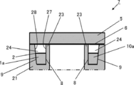
- FIG. 2 is a cross-sectional view of the cylinder block shown in FIG. 1 taken along line xx.
- FIG. 2 is a cross-sectional view of the cylinder block shown in FIG. 1 taken along line xx.
- FIG. 1 is a schematic diagram which shows the thermal insulation structure of the cylinder bore wall of the example of this invention.
- It is typical sectional drawing which shows the internal combustion engine in which the thermal insulation structure of the cylinder bore wall shown in FIG. 5 is installed.
- the cylinder bore wall heat insulation structure according to the present invention is a cylinder bore wall heat insulation structure characterized by having a filling portion for filling the middle and lower part of the groove-like cooling water flow path of the cylinder block.
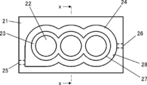
- FIG. 1 is a schematic plan view showing a cylinder block in which a heat retaining structure for a cylinder bore wall according to the present invention is installed.
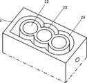
- FIG. 2 is a perspective view of the cylinder block shown in FIG. 3 is a cross-sectional view of the cylinder block shown in FIG. 1 taken along line xx.
- FIG. 4 is a cross-sectional view of the cylinder block shown in FIG. 1 taken along the line xx, illustrating the middle and lower part of the grooved coolant flow path.
- FIG. 1 is a schematic plan view showing a cylinder block in which a heat retaining structure for a cylinder bore wall according to the present invention is installed.
- FIG. 2 is a perspective view of the cylinder block shown in FIG. 3 is a cross-sectional view of the cylinder block shown in FIG. 1 taken along line xx.
- FIG. 4 is a cross-sectional view of the cylinder block shown in FIG. 1 taken along the line xx, illustrating the middle and lower part of the grooved cool
- FIG. 5 is a schematic view showing a heat retaining structure for a cylinder bore wall according to an embodiment of the present invention, and is a view seen from diagonally above the front.
- 6 is a schematic cross-sectional view showing the internal combustion engine in which the cylinder bore wall heat insulation structure shown in FIG. 5 is installed, and is a cross-sectional view taken at a position corresponding to line xx in FIG. .
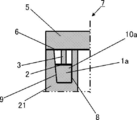
- FIG. 7 is a schematic cross-sectional view showing an internal combustion engine in which the cylinder bore wall heat retaining structure shown in FIG. 5 is installed, and is a cross-sectional view taken at a position corresponding to the yy line in FIG. .
- FIG. 8 is a schematic diagram showing a heat retaining structure for a cylinder bore wall according to an embodiment of the present invention, and is a view seen from diagonally above the front.
- FIG. 9 is a schematic view showing a heat retaining structure for a cylinder bore wall according to an embodiment of the present invention, as viewed from the front.
- FIG. 10 is a schematic view showing a heat insulation structure of a cylinder bore wall according to an embodiment of the present invention, as viewed from the front.
- FIG. 11 is a schematic view showing a heat retaining structure for a cylinder bore wall according to an embodiment of the present invention, and is a view seen from diagonally above the front.
- 12 is a cross-sectional view of the heat insulation structure of the cylinder bore wall shown in FIG. 11, and is a cross-sectional view taken along the line yy in FIG.
- FIG. 13 is a schematic view showing only the core material used in the heat retaining structure for the cylinder bore wall shown in FIG.
- an open deck type cylinder block 21 of a vehicle-mounted internal combustion engine in which the cylinder block heat retaining structure of the present invention is installed includes a bore 22 for moving a piston up and down, and a cooling unit.
- a groove-like cooling water flow path 24 for flowing water is formed.
- a wall that divides the bore 22 and the grooved coolant flow path 24 is a cylinder bore wall 23.
- the cylinder block 21 is formed with a cooling water supply port 25 for supplying cooling water to the grooved cooling water channel 24 and a cooling water discharge port 26 for discharging cooling water from the grooved cooling water channel 24.
- the cylinder block heat retaining structure of the present invention is installed in the grooved cooling water flow path 24, that is, between the wall surface 27 of the cylinder bore wall and the wall surface 28 of the grooved cooling water flow path opposite to the wall surface 27.
- the middle and lower portions of the grooved cooling water flow path 24 will be described.
- the position 34 in the vicinity of the middle between the uppermost part 31 and the lowermost part 32 of the grooved cooling water flow path 24 is indicated by a dotted line, but the position of the grooved cooling water flow path 24 on the lower side from the position 34 near the middle is shown. This portion is referred to as the middle lower portion 33 of the grooved cooling water flow path.
- filling portion 1 a is filled in the middle and lower portions of the groove-shaped cooling water flow path 24 so as to fill the middle and lower portions 33 of the groove-shaped cooling water flow path 24.
- filling the middle and lower portions 33 of the groove-like cooling water flow path 24 means that the flow of the cooling water in the middle and lower portions 33 is blocked, and the wall 27 between the middle and lower portions of the cylinder bore wall 23 and the filling portion. It means that the filling part is filled in the middle lower part 33 so that the cooling water does not flow.
- a water jacket spacer is sometimes installed in the lower part of the grooved cooling water channel. Since it is for adjusting the flow of the cooling water in the lower part, the cooling water flows between the wall surface 27 in the middle and lower part of the cylinder bore wall 23 and the water jacket spacer. Therefore, installing the water jacket spacer in the middle and lower part of the grooved cooling water flow path is different from filling the middle and lower part 33 of the grooved cooling water flow path 24 as in the present invention.
- the cylinder bore wall heat retaining structure 10a shown in FIG. 5 includes a filling portion 1a for filling the middle and lower portions 33 of the grooved cooling water flow path 24, a ring member 2 disposed on the upper surface of the filling portion 1a, and a lower end (one end). And a presser member 3 fixed to the ring member 2.
- FIG. 6 and 7 show the internal combustion engine 7 in which the heat retaining structure 10a of the cylinder bore wall is installed in the grooved cooling water flow path 24.
- FIG. 7 the filling portion 1 a is filled in the middle and lower portions so as to fill the middle and lower portions of the groove-like cooling water flow path 24 of the cylinder block 21.
- the upper end (the other end) of the pressing member 3 is in contact with the head gasket 6.
- the head gasket 6 is pressed from above by the cylinder head 5. Therefore, the pressing member 3 whose upper end is in contact with the head gasket 6 presses the ring member 2, so that the filling portion 1 a is held in the middle and lower portion without moving upward.
- the upper end of the pressing member 3 is brought into contact with the head gasket 6 at a position where the solid portion of the head block 5 is located on the head gasket 6, and the hollow portion of the head block 5 (
- the cooling water channel or the like is not brought into contact with the head gasket 6 at a certain position.
- the head block of the internal combustion engine is provided with a flow path for flowing cooling water, a combustion chamber, a piston, a piston rod, a bolt hole, etc., but the internal combustion engine shown in FIGS. 7, the description of the flow path of the cooling water provided in the head block 5 is omitted for the convenience of explanation, and the description is simplified.
- the contact surface 8 on the cylinder bore wall 23 side of the filling portion 1 a is in contact with the wall surface 27 in the lower part of the cylinder bore wall 23.
- the cooling water is blocked from flowing through.
- the contact surface 9 on the opposite side to the cylinder bore wall 23 of the filling portion 1 a is in contact with the middle and lower wall surface 28 on the opposite side to the wall surface 27 of the cylinder bore wall 23, so that it is opposite to the wall surface 27 of the cylinder bore wall 23.
- the cooling water is blocked from flowing between the side wall surface 28 and the filling portion 1a. Therefore, the cooling water does not flow in the middle and lower part of the groove-like cooling water flow path 24, so that the middle and lower part of the cylinder bore wall 23 is kept warm.
- the cylinder bore wall heat insulation structure according to the present invention is a cylinder bore wall heat insulation structure characterized by having a filling portion for filling the middle and lower part of the groove-like cooling water flow path of the cylinder block.
- the filling portion according to the heat insulation structure of the cylinder bore wall according to the present invention fills the middle and lower portions of the groove-shaped cooling water flow path by filling the middle and lower portions of the groove-shaped cooling water flow path, Any material, shape and structure that can block the flow of the cooling water can be used.
- Examples of the material of the filling portion include rubbers such as solid rubber, expanded rubber, foamed rubber, and soft rubber, and silicone-based gel materials.
- the composition of the solid rubber includes natural rubber, butadiene rubber, ethylene propylene diene rubber (EPDM), nitrile butadiene rubber (NBR), silicone rubber, fluorine rubber and the like.
- EPDM ethylene propylene diene rubber
- NBR nitrile butadiene rubber
- silicone rubber fluorine rubber and the like.
- the expanded rubber examples include heat-sensitive expanded rubber.
- Thermally-expandable rubber is a composite in which a base foam material is impregnated with a thermoplastic material having a melting point lower than that of the base foam material and is compressed. At room temperature, the compressed state is maintained by at least the cured product of the thermoplastic material on the surface layer. In addition, the cured material of the thermoplastic material is softened by heating, and the compressed state is released.
- the heat-sensitive expansion rubber include heat-sensitive expansion rubber described in JP-A-2004-143262.
- the filling portion When the material of the filling portion is heat-sensitive expansion rubber, the filling portion is installed in the middle and lower part of the groove-shaped cooling water flow path, and heat is applied to the heat-sensitive expansion rubber, so that the heat-sensitive expansion rubber expands and the groove-shaped cooling water flow path
- the heat-expandable rubber is deformed so as to fill the middle and lower parts of the cylinder, and the flow of the cooling water between the contact surface and the wall surface of the filling portion is blocked by pressing the thermal expansion rubber against the wall surface of the cylinder bore wall and the opposite wall surface.
- Examples of the base foam material relating to the heat-expandable rubber include various polymer materials such as rubber, elastomer, thermoplastic resin, and thermosetting resin.
- natural rubber, chloropropylene rubber, styrene butadiene rubber, nitrile Examples include butadiene rubber, ethylene propylene diene terpolymer, various synthetic rubbers such as silicone rubber, fluoro rubber, and acrylic rubber, various elastomers such as soft urethane, various thermosetting resins such as hard urethane, phenol resin, and melamine resin. It is done.
- thermoplastic material related to the heat-expandable rubber those having any of glass transition point, melting point or softening temperature of less than 120 ° C are preferable.
- Thermoplastic materials related to heat-expandable rubber include polyethylene, polypropylene, polystyrene, polyvinyl chloride, polyvinylidene chloride, polyvinyl acetate, polyacrylate ester, styrene butadiene copolymer, chlorinated polyethylene, polyvinylidene fluoride, ethylene acetate Vinyl copolymer, ethylene vinyl acetate vinyl chloride acrylate copolymer, ethylene vinyl acetate acrylate copolymer, ethylene vinyl acetate vinyl chloride copolymer, nylon, acrylonitrile butadiene copolymer, polyacrylonitrile, polyvinyl chloride , Polychloroprene, polybutadiene, thermoplastic polyimide, polyacetal, polyphenylene sulfide, poly
- examples of the expanded rubber include water-swellable rubber.
- the water-swellable rubber is a material in which a water-absorbing substance is added to rubber, and is a rubber material having a shape retaining property that absorbs water and swells and maintains an expanded shape.
- examples of the water-swellable rubber include a rubber material in which a water-absorbing substance such as a cross-linked product of neutralized polyacrylic acid, a cross-linked product of starch acrylic acid graft copolymer, a cross-linked carboxymethyl cellulose salt, and polyvinyl alcohol is added to the rubber. Can be mentioned.
- water-swellable rubber examples include water-swellable rubbers containing ketiminated polyamide resins, glycidyl etherified products, water-absorbing resins and rubbers described in JP-A-9-208752.
- the filling part is installed in the middle and lower part of the groove-like cooling water flow path, the cooling water is flowed, and the water-swellable rubber absorbs water, so that the water-swellable rubber Expands and fills the lower part of the grooved cooling water flow path, and the water-swellable rubber is pressed against the wall surface of the cylinder bore wall and the opposite wall surface, thereby The flow of cooling water in between is interrupted.
- the foam rubber is a porous rubber.
- the foam rubber include sponge-like foam rubber having an open cell structure, foam rubber having a closed cell structure, and semi-closed foam rubber.
- Specific examples of the material for the foam rubber include ethylene propylene diene terpolymer, silicone rubber, nitrile butadiene copolymer, silicone rubber, and fluoro rubber.
- the foaming rate of the foamed rubber is not particularly limited and is appropriately selected, and the water content of the filling part can be adjusted by adjusting the foaming rate.
- the foaming ratio of foamed rubber refers to the density ratio before and after foaming represented by ((density before foaming ⁇ density after foaming) / density before foaming) ⁇ 100.
- the filling part When the material of the filling part is foamed rubber, it is installed in the grooved cooling water flow path, the filling part is pressed from above, and the foamed rubber is deformed to fill the lower part of the grooved cooling water flow path, and foamed.
- the rubber When the rubber is pressed against the wall surface of the cylinder bore wall and the wall surface on the opposite side, the flow of the cooling water between the contact surface of the filling portion and the wall surface is blocked.
- the material of the filling portion is a material that can contain water, such as water-swellable rubber and foam rubber, it is installed in the groove-shaped cooling water flow path, and when the cooling water is poured into the groove-shaped cooling water flow path, The filling part contains water.
- the range in which the moisture content of the filling portion is set when the cooling water is caused to flow through the grooved cooling water flow path is appropriately selected depending on the operating conditions of the internal combustion engine.
- a moisture content refers to the weight moisture content represented by (cooling water weight / (filler weight + cooling water weight)) ⁇ 100.
- all of the filling part may be made of the material of the filling part, for example, solid rubber, expanded rubber, foamed rubber, or the like, or is bonded to both side surfaces of the core material and the core material.
- the filling portion may be made of a material such as solid rubber, expanded rubber, foamed rubber, or the like.
- the shape of the filling part before filling the middle and lower part of the grooved cooling water channel is not particularly limited, and the grooved cooling water channel is filled by filling the middle and lower part of the grooved cooling water channel. Any shape that can block the flow of the cooling water so that the cooling water does not flow in the middle and lower portion of the wall may be used.
- the shape of the filling part before filling the lower part of the grooved cooling water channel is a shape whose width is slightly larger than the width of the lower part of the grooved cooling water channel.
- the filling portion made of solid rubber having a width slightly larger than the width of the middle and lower part of the groove-like cooling water flow path is pushed into the groove-like cooling water flow path so that the contact surface on the cylinder bore wall side of the filling part becomes The cooling water is pressed against the wall surface of the cylinder bore wall, covers the entire wall surface of the middle and lower part of the cylinder bore wall, and fills the middle and lower part of the grooved cooling water flow path. And the flow of the cooling water in the lower part of the groove-shaped cooling water flow path can be blocked.
- cooling water is contained in the concavo-convex part on the contact surface of the filling part with the wall surface of the cylinder bore wall and the contact surface with the wall surface opposite to the wall surface of the cylinder bore wall.
- the material of the filling part is solid rubber
- cooling water is contained in the concavo-convex part on the contact surface of the filling part with the wall surface of the cylinder bore wall and the contact surface with the wall surface opposite to the wall surface of the cylinder bore wall.
- the shape of the filling part before being filled in the lower part of the grooved cooling water flow path is installed in the lower part of the grooved cooling water flow path and is expanded by heat or water. And covering the whole wall surface of the middle and lower part of the cylinder bore wall and filling the middle and lower part of the grooved cooling water flow path to block the flow of the cooling water between the wall surface of the middle and lower part of the cylinder bore wall and the filling part, And it is the shape which can interrupt
- the shape of the filling part before being filled in the lower part of the grooved cooling water flow path is installed at the lower part of the grooved cooling water flow path and is deformed by being pressed from above. Then, cover the entire wall surface at the middle and lower part of the cylinder bore wall and fill the middle and lower part of the grooved cooling water flow path to block the flow of cooling water between the wall surface at the middle and lower part of the cylinder bore wall and the filling part. And the shape which can interrupt
- the middle and lower part of the grooved cooling water flow path does not mean the part below the middle part between the uppermost part and the lowermost part of the grooved cooling water flow path. It means the part. Accordingly, the position from the lowest part of the grooved cooling water flow path to the filling part, that is, the position of the upper surface of the filling part in the vertical direction of the grooved cooling water flow path is appropriately selected. .
- a filling portion made of a material such as solid rubber, expanded rubber or foam rubber is disposed on the top surface of the filling portion.
- a holding member for pressing the ring member by having the lower end fixed to the ring member and the upper end contacting the head gasket (hereinafter referred to as a heat retaining structure for the cylinder bore wall) (It is also referred to as a form example (1)).
- An example (1) of the heat insulation structure of the cylinder bore wall is installed in the grooved coolant flow path of the cylinder block, and the cylinder block, the head gasket, and the cylinder head are assembled to hold the cylinder head against the cylinder head. Since the gasket prevents the presser member from moving upward, the presser member can hold the ring member moving upward when the internal combustion engine is operating. Therefore, according to the configuration example (1) of the heat insulation structure of the cylinder bore wall, when the internal combustion engine is operated, the filling portion can be held in the middle and lower part of the groove-like cooling water flow path that needs to be kept warm. .
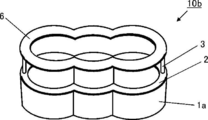
- the cylinder bore wall heat retaining structure 10 b includes a filling portion 1 a, a ring member 2, a pressing member 3, and a head gasket 6.
- the ring member 2 is disposed on the upper surface of the filling portion 1a.
- the pressing member 3 is a member for pressing the ring member 2 having a lower end fixed to the ring member 2 and an upper end fixed to the head gasket 6.
- the cylinder bore wall thermal insulation structure of the present invention includes a filling portion made of a material such as solid rubber, expanded rubber or foamed rubber, a ring member disposed on the upper surface of the filling portion, a head gasket,
- a form example having a holding member for holding the ring member having a lower end fixed to the ring member and an upper end fixed to the head gasket (hereinafter referred to as a form example (2) of the heat retaining structure of the cylinder bore wall) To be described).
- An example (2) of the heat retaining structure of the cylinder bore wall is installed in the grooved coolant flow path of the cylinder block, and the cylinder block, the head gasket, and the cylinder head are assembled to hold the cylinder head against the cylinder head.
- the presser member can hold the ring member moving upward when the internal combustion engine is operating. Therefore, according to the embodiment (2) of the heat insulation structure of the cylinder bore wall, when the internal combustion engine is operated, the filling portion can be held in the middle and lower part of the grooved coolant flow path that needs to be kept warm. .
- each of the heat retaining structures 10c and 10d on the cylinder bore wall includes the filling portion 1a, the ring member 2, and the pressing member 13.
- the ring member 2 is disposed on the upper surface of the filling portion 1a.
- the presser member 3 has a lower end fixed to the ring member 2, and fin members (fin members 11 in FIG. 9 and fin members 12 in FIG. 10) that generate a downward force when the cooling water flows are on the side surfaces. It is a member provided and a member for pressing the ring member 2.
- the fin member 11 has a shape in which the water flow channel on the lower surface side of the fin member 11 is longer than the water flow channel on the upper surface side of the fin member 11, and a downward force is generated by the flow of the cooling water. It is a member to be generated.
- the fin member 12 has a shape in which the rear side in the flow direction of the cooling water is bent obliquely upward, and generates a downward force when the cooling water flows.
- the cylinder bore wall heat retaining structure of the present invention includes a filling portion made of a material such as solid rubber, expanded rubber or foam rubber, a ring member disposed on the upper surface of the filling portion, and a lower end having a ring member.
- a holding member having a fin member provided on the side surface for generating a downward force by the flow of cooling water (hereinafter referred to as a configuration example (3) of the heat retaining structure of the cylinder bore wall) To be described).
- the configuration example (3) of the heat retaining structure of the cylinder bore wall is installed in the grooved cooling water channel of the cylinder block, and the holding member presses the ring member by flowing the cooling water into the grooved cooling water channel. Therefore, when the internal combustion engine is operated, the pressing member can hold the ring member moving upward. Therefore, according to the configuration example (3) of the heat insulation structure of the cylinder bore wall, when the internal combustion engine is operated, the filling part can be held in the middle and lower part of the grooved coolant flow path that needs to be kept warm. .
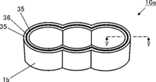
- the cylinder bore wall heat retaining structure 10e includes a core member 36 and rubber members 35 attached to both side surfaces of the core member 36.
- the rubber member 35 attached to the side surfaces on both sides of the core member 36 is filled in the lower part of the grooved cooling water flow path 1b. It is.
- the shape of the core member 36 of the cylinder bore wall heat retaining structure 10e is the same shape as the central portion in the width direction of the middle and lower part of the groove-like cooling water flow path.
- the cylinder bore wall heat insulation structure of the present invention includes a filling portion composed of a core material and a rubber material such as solid rubber, expanded rubber, or foam rubber that is attached to both side surfaces of the core material.
- a filling portion composed of a core material and a rubber material such as solid rubber, expanded rubber, or foam rubber that is attached to both side surfaces of the core material.
- the form example which it has (Hereinafter, it describes also as the form example (4) of the heat insulation structure of a cylinder bore wall.).
- the heat insulation structure of the cylinder bore wall according to the present invention includes a filling portion composed of a core material and a rubber material such as solid rubber, expanded rubber, or foam rubber adhered to both side surfaces of the core material, and a lower end that is a core. It is also described as a configuration example (hereinafter referred to as a configuration example (5) of the heat retaining structure of the cylinder bore wall) having a holding member that is fixed to the material and has an upper end that abuts against the head gasket to press the core material. ).
- the filling part is a material capable of containing water such as water-swellable rubber and foamed rubber
- the water contained in the material constituting the filling part is filled. It is gradually replaced with the cooling water flowing on the upper side of the section. Therefore, the temperature of the cylinder bore wall can be adjusted by adjusting the moisture content of the material constituting the filling portion.
- the water content of the material constituting the filling portion is appropriately selected depending on the operating conditions of the internal combustion engine such as the temperature of the cylinder bore wall, the temperature or the flow rate of the cooling water.
- the shape (1) of the heat retaining structure for the cylinder bore wall, the heat retaining structure for the cylinder bore wall In the configuration example having the ring member as in the configuration example (2) and the configuration example (3) of the heat insulation structure of the cylinder bore wall, by adjusting the width of the ring member, the groove-shaped cooling water flow path of the ring member is adjusted. The vertical position can be adjusted.
- the grooved cooling water flow path of the cylinder block is filled with a filling member in the lower part of the grooved cooling water flow path of the cylinder block to fill the middle and lower parts of the grooved cooling water flow path.
- the heat retaining structure for the cylinder bore according to the present invention (for example, the heat retaining structure for the cylinder bore wall)
- An example is a method in which a structural example (5), etc.) is installed in the grooved cooling water flow path and the filling portion is filled in the lower part of the grooved cooling water flow path.
- the internal combustion engine of the present invention has a cylinder block, a cylinder head, a head gasket, and a heat retaining structure for the cylinder bore wall of the present invention,
- the lower part of the grooved coolant flow path of the cylinder block is filled by the filling part of the heat insulation structure of the cylinder bore wall of the present invention,
- the internal combustion engine of the present invention further includes a piston, a piston rod, a crankshaft, a combustion chamber, an intake / exhaust valve, and the like.
- the automobile of the present invention is an automobile having the internal combustion engine of the present invention.
- the difference in deformation amount between the upper side and the lower side of the cylinder bore wall of the internal combustion engine can be reduced, and the friction of the piston can be reduced, so that a fuel-saving internal combustion engine can be provided.
Landscapes
- Engineering & Computer Science (AREA)
- Chemical & Material Sciences (AREA)
- Combustion & Propulsion (AREA)
- Mechanical Engineering (AREA)
- General Engineering & Computer Science (AREA)
- Cylinder Crankcases Of Internal Combustion Engines (AREA)
Abstract
シリンダブロックの溝状冷却水流路の中下部を埋めるための充填部を有することを特徴とするシリンダボア壁の保温構造体である。 これによれば、シリンダボア壁の壁温の均一性が高い内燃機関を提供することができる。
Description
本発明は、内燃機関のシリンダブロックのシリンダボア壁を保温するための保温構造体、保温方法、該保温構造体を備える内燃機関及び該内燃機関を有する自動車に関する。
内燃機関では、ボア内のピストンの上死点で燃料の爆発が起こり、その爆発によりピストンが押し下げられるという構造上、シリンダボア壁の上側は温度が高くなり、下側は温度が低くなる。そのため、シリンダボア壁の上側と下側では、熱変形量に違いが生じ、上側は大きく膨張し、一方、下側の膨張が小さくなる。
その結果、ピストンのシリンダボア壁との摩擦抵抗が大きくなり、これが、燃費を下げる要因となっている。
また、ピストンとシリンダボア壁との隙間が、シリンダボア壁の上側と下側とでは異なることになるため、ピストンが振動する。これが、クランクシャフトの揺れにつながり、エネルギーロスの要因となっている。
そのため、シリンダボア壁の上側と下側とで熱変形量の違いを少なくすることが求められている。
そこで、従来より、シリンダボア壁の壁温を均一にするために、溝状冷却水流路内にスペーサーを設置し、溝状冷却水流路内の冷却水の水流を調節して、冷却水によるシリンダボア壁の上側の冷却効率と及び下側の冷却効率を制御することが試みられてきた。例えば、特許文献1には、内燃機関のシリンダブロックに形成された溝状冷却用熱媒体流路内に配置されることで該溝状冷却用熱媒体流路内を複数の流路に区画する流路区画部材であって、前記溝状冷却用熱媒体流路の深さに満たない高さに形成され、前記溝状冷却用熱媒体流路内をボア側流路と反ボア側流路とに分割する壁部となる流路分割部材と、前記流路分割部材から前記溝状冷却用熱媒体流路の開口部方向に向けて形成され、かつ先端縁部が前記溝状冷却用熱媒体流路の一方の内面を越えた形に可撓性材料で形成されていることにより、前記溝状冷却用熱媒体流路内への挿入完了後は自身の撓み復元力により前記先端縁部が前記内面に対して前記溝状冷却用熱媒体流路の深さ方向の中間位置にて接触することで前記ボア側流路と前記反ボア側流路とを分離する可撓性リップ部材と、を備えたことを特徴とする内燃機関冷却用熱媒体流路区画部材が開示されている。
ところが、引用文献1の内燃機関冷却用熱媒体流路区画部材によれば、ある程度のシリンダボア壁の壁温の均一化が図れるので、シリンダボア壁の上側と下側との熱変形量の違いを少なくすることができるものの、近年、更に、シリンダボア壁の上側と下側とで熱変形量の違いを少なくすることが求められている。
従って、本発明の課題は、シリンダボア壁の壁温の均一性が高い保温構造体、保温方法、該保温構造体を備える内燃機関及び該内燃機関を有する自動車を提供することにある。
本発明者らは、上記従来技術における課題を解決すべく、鋭意研究を重ねた結果、シリンダブロックの溝状冷却水流路の中下部を、充填部で埋めて、溝状冷却水流路の中下部の冷却水の流れを遮断することにより、シリンダボア壁の中下部が保温され、そのことにより、シリンダボア壁の中下部の温度を高めて、シリンダボア壁全体の均一化が図れること等を見出し、本発明を完成させるに至った。
すなわち、本発明(1)は、シリンダブロックの溝状冷却水流路の中下部を埋めるための充填部を有することを特徴とするシリンダボア壁の保温構造体を提供するものである。
また、本発明(2)は、前記充填部が、ソリッドゴム、膨張ゴム又は発泡ゴムからなり、
該充填部の上面に配置されているリング部材と、
下端が該リング部材に固定されており、上端がヘッドガスケットに当接することにより、該リング部材を押えるための押え部材と、
を有することを特徴とする(1)のシリンダボア壁の保温構造体を提供するものである。
該充填部の上面に配置されているリング部材と、
下端が該リング部材に固定されており、上端がヘッドガスケットに当接することにより、該リング部材を押えるための押え部材と、
を有することを特徴とする(1)のシリンダボア壁の保温構造体を提供するものである。
また、本発明(3)は、前記充填部が、ソリッドゴム、膨張ゴム又は発泡ゴムからなり、
該充填部の上面に配置されているリング部材と、
ヘッドガスケットと、
下端が該リング部材に固定され、上端がヘッドガスケットに固定されている、該リング部材を押えるための押え部材と、
を有することを特徴とする(1)のシリンダボア壁の保温構造体を提供するものである。
該充填部の上面に配置されているリング部材と、
ヘッドガスケットと、
下端が該リング部材に固定され、上端がヘッドガスケットに固定されている、該リング部材を押えるための押え部材と、
を有することを特徴とする(1)のシリンダボア壁の保温構造体を提供するものである。
また、本発明(4)は、前記充填部が、ソリッドゴム、膨張ゴム又は発泡ゴムからなり、
該充填部の上面に配置されているリング部材と、
下端が該リング部材に固定され、冷却水の流れにより下向きの力を発生させるフィン部材が側面に設けられている押さえ部材と、
を有することを特徴とする(1)のシリンダボア壁の保温構造体を提供するものである。
該充填部の上面に配置されているリング部材と、
下端が該リング部材に固定され、冷却水の流れにより下向きの力を発生させるフィン部材が側面に設けられている押さえ部材と、
を有することを特徴とする(1)のシリンダボア壁の保温構造体を提供するものである。
また、本発明(5)は、前記充填部が、芯材と、該芯材の両側面に貼り付けられているソリッドゴム、膨張ゴム又は発泡ゴムと、からなることを特徴とする(1)のシリンダボア壁の保温構造体を提供するものである。
また、本発明(6)は、下端が前記芯材に固定されており、上端がヘッドガスケットに当接することにより、前記芯材を押えるための押え部材を有することを特徴とする(5)のシリンダボア壁の保温構造体を提供するものである。
また、本発明(7)は、シリンダブロックの溝状冷却水流路の中下部に、充填部材を充填して、該溝状冷却水流路の中下部を埋めることにより、該溝状冷却水流路の中下部の冷却水の流れを遮断して、シリンダボア壁の中下部を保温することを特徴とするシリンダボア壁の保温方法を提供するものである。
また、本発明(8)は、シリンダブロックと、シリンダヘッドと、ヘッドガスケットと、(1)~(6)いずれかのシリンダボア壁の保温構造体と、を有し、
該シリンダボア壁の保温構造体の充填部により、シリンダブロックの溝状冷却水流路の中下部が埋められていることを特徴とする内燃機関を提供するものである。
該シリンダボア壁の保温構造体の充填部により、シリンダブロックの溝状冷却水流路の中下部が埋められていることを特徴とする内燃機関を提供するものである。
また、本発明(9)は、(8)の内燃機関を有することを特徴とする自動車を提供するものである。
本発明によれば、内燃機関のシリンダボア壁の均一化が図れる。そのため、本発明によれば、シリンダボア壁の上側と下側とで熱変形量の違いを少なくすることができる。
本発明のシリンダボア壁の保温構造体は、シリンダブロックの溝状冷却水流路の中下部を埋めるための充填部を有することを特徴とするシリンダボア壁の保温構造体である。
本発明のシリンダボア壁の保温構造体及び本発明の内燃機関について、図1~図13を参照して説明する。図1は、本発明のシリンダボア壁の保温構造体が設置されるシリンダブロックを示す模式的な平面図である。図2は、図1に示すシリンダブロックの斜視図である。図3は、図1に示すシリンダブロックのx-x線断面図である。図4は、図1に示すシリンダブロックのx-x線断面図であり、溝状冷却水流路の中下部を説明するための図である。図5は、本発明の形態例のシリンダボア壁の保温構造体を示す模式図であり、正面斜め上から見た図である。図6は、図5に示すシリンダボア壁の保温構造体が設置されている内燃機関を示す模式的な断面図であり、図5中のx-x線に相当する位置で切った断面図である。図7は、図5に示すシリンダボア壁の保温構造体が設置されている内燃機関を示す模式的な断面図であり、図5中のy-y線に相当する位置で切った断面図である。図8は、本発明の形態例のシリンダボア壁の保温構造体を示す模式図であり、正面斜め上から見た図である。図9は、本発明の形態例のシリンダボア壁の保温構造体を示す模式図であり、正面から見た図である。図10は、本発明の形態例のシリンダボア壁の保温構造体を示す模式図であり、正面から見た図である。図11は、本発明の形態例のシリンダボア壁の保温構造体を示す模式図であり、正面斜め上から見た図である。図12は、図11に示すシリンダボア壁の保温構造体の断面図であり、図11中のy-y線で切った断面図である。図13は、図11に示すシリンダボア壁の保温構造体に用いられている芯材のみを示す模式図であり、正面斜め上から見た図である。
図1~図3に示すように、本発明のシリンダブロックの保温構造体が設置される車両搭載用内燃機関のオープンデッキ型のシリンダブロック21には、ピストンが上下するためのボア22、及び冷却水を流すための溝状冷却水流路24が形成されている。そして、ボア22と溝状冷却水流路24とを区切る壁が、シリンダボア壁23である。また、シリンダブロック21には、溝状冷却水流路24へ冷却水を供給するための冷却水供給口25及び冷却水を溝状冷却水流路24から排出するための冷却水排出口26が形成されている。そして、溝状冷却水流路24内に、つまり、シリンダボア壁の壁面27と壁面27とは反対側の溝状冷却水流路の壁面28の間に、本発明のシリンダブロックの保温構造体が設置される。
図4を参照して、溝状冷却水流路24の中下部について説明する。図4では、溝状冷却水流路24の最上部31と最下部32の中間近傍の位置34を、点線で示しているが、この中間近傍の位置34から下側の溝状冷却水流路24の部分を、溝状冷却水流路の中下部33と呼ぶ。
溝状冷却水流路24には、例えば、図5に示すシリンダボア壁の保温構造体10aが設置される。このとき、充填部1aは、溝状冷却水流路24の中下部33を埋めるように、溝状冷却水流路24の中下部に充填される。なお、本発明において、溝状冷却水流路24の中下部33を埋めるとは、中下部33の冷却水の流れが遮断されて、シリンダボア壁23の中下部の壁面27と充填部との間に、冷却水が流れないように、中下部33に充填部を充填することを指す。
内燃機関では、溝状冷却水流路の中下部の冷却水流れを調節するために、溝状冷却水流路の中下部にウォータージャケットスペーサーが設置されることがあるが、ウォータージャケットスペーサーは、あくまでも中下部の冷却水の流れを調節するためのものであるため、シリンダボア壁23の中下部の壁面27とウォータージャケットスペーサーとの間に、冷却水は流れる。よって、溝状冷却水流路の中下部にウォータージャケットスペーサーを設置することは、本発明のように溝状冷却水流路24の中下部33を埋めることとは、異なる。
図5に示すシリンダボア壁の保温構造体10aは、溝状冷却水流路24の中下部33を埋めるための充填部1aと、充填部1aの上面に配置されるリング部材2と、下端(一端)がリング部材2に固定されている押え部材3と、からなる。
図6及び図7には、シリンダボア壁の保温構造体10aが、溝状冷却水流路24に設置されている内燃機関7を示す。内燃機関7では、充填部1aが、シリンダブロック21の溝状冷却水流路24の中下部を埋めるように、中下部に充填されている。押え部材3の上端(他端)は、ヘッドガスケット6に当接している。ヘッドガスケット6は、シリンダヘッド5により上側から押え付けられている。そのため、ヘッドガスケット6に上端が当接している押え部材3が、リング部材2を押えるので、充填部1aは、上に移動せずに中下部に保持される。このとき、押え部材3の上端は、ヘッドガスケット6の上にヘッドブロック5の中実部がある位置のヘッドガスケット6に当接させるようにし、ヘッドガスケット6の上にヘッドブロック5の中空部(冷却水の流路等)がある位置のヘッドガスケット6には当接させないようにする。なお、通常、内燃機関のヘッドブロックには、冷却水を流すための流路や、燃焼室や、ピストン、ピストンロッド、ボルト穴等が設けられているが、図6及び図7に示す内燃機関7では、説明の都合上、ヘッドブロック5に設けられている冷却水の流路等の記載を省略し、記載を簡略化した。
内燃機関7では、充填部1aのシリンダボア壁23側の接触面8が、シリンダボア壁23の中下部の壁面27に接しているので、シリンダボア壁23の中下部の壁面27と充填部1aとの間に冷却水が流れるのが遮断される。また、充填部1aのシリンダボア壁23とは反対側の接触面9が、シリンダボア壁23の壁面27とは反対側の中下部の壁面28と接しているので、シリンダボア壁23の壁面27とは反対側の壁面28と充填部1aとの間に冷却水が流れるのが遮断される。そのため、溝状冷却水流路24の中下部には、冷却水が流れないので、シリンダボア壁23の中下部が保温される。
本発明のシリンダボア壁の保温構造体は、シリンダブロックの溝状冷却水流路の中下部を埋めるための充填部を有することを特徴とするシリンダボア壁の保温構造体である。
本発明のシリンダボア壁の保温構造体に係る充填部は、溝状冷却水流路の中下部に充填されることにより、溝状冷却水流路の中下部を埋めて、溝状冷却水流路の中下部の冷却水の流れを遮断することができる材質、形状及び構造であればよい。
充填部の材質としては、例えば、ソリッドゴム、膨張ゴム、発泡ゴム、軟性ゴム等のゴム、シリコーン系ゲル状素材等が挙げられる。
ソリッドゴムの組成としては、天然ゴム、ブタジエンゴム、エチレンプロピレンジエンゴム(EPDM)、ニトリルブタジエンゴム(NBR)、シリコーンゴム、フッ素ゴム等が挙げられる。充填部の材質がソリッドゴムの場合は、充填部が溝状冷却水流路の中下部に押し込まれて、ソリッドゴムが、シリンダボア壁の壁面及びその反対側の壁面に押し付けられることにより、充填部の接触面と壁面との間の冷却水の流れが遮断される。
膨張ゴムとしては、感熱膨張ゴムが挙げられる。感熱膨張ゴムは、ベースフォーム材にベースフォーム材より融点が低い熱可塑性物質を含浸させ圧縮した複合体であり、常温では少なくともその表層部に存在する熱可塑性物質の硬化物により圧縮状態が保持され、且つ、加熱により熱可塑性物質の硬化物が軟化して圧縮状態が開放される材料である。感熱膨張ゴムとしては、例えば、特開2004-143262号公報に記載の感熱膨張ゴムが挙げられる。充填部の材質が感熱膨張ゴムの場合は、充填部が溝状冷却水流路の中下部に設置され、感熱膨張ゴムに熱が加えられることで、感熱膨張ゴムが膨張して溝状冷却水流路の中下部を埋めるように変形して、感熱膨張ゴムがシリンダボア壁の壁面及びその反対側の壁面に押し付けられることにより、充填部の接触面と壁面との間の冷却水の流れが遮断される。
感熱膨張ゴムに係るベースフォーム材としては、ゴム、エラストマー、熱可塑性樹脂、熱硬化性樹脂等の各種高分子材料が挙げられ、具体的には、天然ゴム、クロロプロピレンゴム、スチレンブタジエンゴム、ニトリルブタジエンゴム、エチレンプロピレンジエン三元共重合体、シリコーンゴム、フッ素ゴム、アクリルゴム等の各種合成ゴム、軟質ウレタン等の各種エラストマー、硬質ウレタン、フェノール樹脂、メラミン樹脂等の各種熱硬化性樹脂が挙げられる。
感熱膨張ゴムに係る熱可塑性物質としては、ガラス転移点、融点又は軟化温度のいずれかが120℃未満であるものが好ましい。感熱膨張ゴムに係る熱可塑性物質としては、ポリエチレン、ポリプロピレン、ポリスチレン、ポリ塩化ビニル、ポリ塩化ビニリデン、ポリ酢酸ビニル、ポリアクリル酸エステル、スチレンブタジエン共重合体、塩素化ポリエチレン、ポリフッ化ビニリデン、エチレン酢酸ビニル共重合体、エチレン酢酸ビニル塩化ビニルアクリル酸エステル共重合体、エチレン酢酸ビニルアクリル酸エステル共重合体、エチレン酢酸ビニル塩化ビニル共重合体、ナイロン、アクリロニトリルブタジエン共重合体、ポリアクリロニトリル、ポリ塩化ビニル、ポリクロロプレン、ポリブタジエン、熱可塑性ポリイミド、ポリアセタール、ポリフェニレンサルファイド、ポリカーボネート、熱可塑性ポリウレタン等の熱可塑性樹脂、低融点ガラスフリット、でんぷん、はんだ、ワックス等の各種熱可塑性化合物が挙げられる。
また、膨張ゴムとしては、水膨潤性ゴムが挙げられる。水膨潤性ゴムは、ゴムに吸水性物質が添加された材料であり、水を吸収して膨潤し、膨張した形状を保持する保形性を有するゴム材である。水膨潤性ゴムとしては、例えば、ポリアクリル酸中和物の架橋物、デンプンアクリル酸グラフト共重合体架橋物、架橋カルボキシメチルセルロース塩、ポリビニルアルコール等の吸水性物質がゴムに添加されたゴム材が挙げられる。また、水膨潤性ゴムとしては、例えば、特開平9-208752号公報に記載されているケチミン化ポリアミド樹脂、グリシジルエーテル化物、吸水性樹脂及びゴムを含有する水膨潤性ゴムが挙げられる。充填部の材質が水膨潤性ゴムの場合は、充填部が溝状冷却水流路の中下部に設置され冷却水が流されて、水膨潤性ゴムが水を吸収することで、水膨潤性ゴムが膨張して溝状冷却水流路の中下部を埋めるように変形して、水膨潤性ゴムがシリンダボア壁の壁面及びその反対側の壁面に押し付けられることにより、充填部の接触面と壁面との間の冷却水の流れが遮断される。
発泡ゴムは、多孔質のゴムである。発泡ゴムとしては、連続気泡構造を有するスポンジ状の発泡ゴム、独立気泡構造を有する発泡ゴム、半独立発泡ゴム等があげられる。発泡ゴムの材質としては、具体的には、例えば、エチレンプロピレンジエン三元共重合体、シリコーンゴム、ニトリルブタジエン共重合体、シリコーンゴム、フッ素ゴム等が挙げられる。発泡ゴムの発泡率は、特に制限されず、適宜選択され、発泡率を調節することにより、充填部の含水率を調節することができる。なお、発泡ゴムの発泡率とは、((発泡前密度-発泡後密度)/発泡前密度)×100で表される発泡前後の密度割合を指す。充填部の材質が発泡ゴムの場合は、溝状冷却水流路内に設置され、充填部が上から押し付けられて、発泡ゴムが溝状冷却水流路の中下部を埋めるように変形して、発泡ゴムがシリンダボア壁の壁面及びその反対側の壁面に押し付けられることにより、充填部の接触面と壁面との間の冷却水の流れが遮断される。
充填部の材質が水膨潤性ゴム、発泡ゴムのように、含水することができる材料の場合、溝状冷却水流路内に設置され、溝状冷却水流路に冷却水が流されたときに、充填部が含水する。溝状冷却水流路に冷却水が流されたときに、充填部の含水率を、どのような範囲とするかは、内燃機関の運転条件等により、適宜選択される。なお、含水率とは、(冷却水重量/(充填剤重量+冷却水重量))×100で表される重量含水率を指す。
充填部は、充填部の全てが、上記充填部の材質、例えば、ソリッドゴム、膨張ゴム、発泡ゴム等で構成されていてもよいし、あるいは、芯材と芯材の両側面に張り合わされている上記充填部の材質、例えば、ソリッドゴム、膨張ゴム、発泡ゴム等とにより構成されていてもよい。
溝状冷却水流路の中下部に充填される前の充填部の形状は、特に制限されず、溝状冷却水流路の中下部に充填されることにより、中下部を埋めて溝状冷却水流路の中下部に冷却水が流れないように冷却水の流れを遮断することができる形状であればよい。
例えば、充填部の材質がソリッドゴムの場合は、溝状冷却水流路の中下部に充填される前の充填部の形状は、幅が溝状冷却水流路の中下部の幅より少し大きい形状であることが好ましい。幅が溝状冷却水流路の中下部の幅より少し大きい形状のソリッドゴムで構成されている充填部は、溝状冷却水流路内に押し込まれることにより、充填部のシリンダボア壁側の接触面が、シリンダボア壁の壁面に押し付けられ、シリンダボア壁の中下部の壁面全体を覆い、且つ、溝状冷却水流路の中下部を埋めて、シリンダボア壁の中下部の壁面と充填部との間の冷却水の流れを遮断すること、及び溝状冷却水流路の中下部の冷却水の流れを遮断することができる。
また、充填部の材質がソリッドゴムの場合は、充填部のシリンダボア壁の壁面との接触面及びシリンダボア壁の壁面とは反対側の壁面との接触面に、凹凸部に冷却水が含まれて、溝状冷却水流路24との間に緩やかな熱輸送がなされるような凹凸部を設けることにより、充填部のシリンダボア壁との接触面における冷却水の突沸やソリッドゴムの部分溶融を防ぐことができる。
充填部の材質が、膨張ゴムの場合、溝状冷却水流路の中下部に充填される前の充填部の形状は、溝状冷却水流路の中下部に設置され、熱又は水により膨張したときに、シリンダボア壁の中下部の壁面全体を覆い、且つ、溝状冷却水流路の中下部を埋めて、シリンダボア壁の中下部の壁面と充填部との間の冷却水の流れを遮断すること、及び溝状冷却水流路の中下部の冷却水の流れを遮断することができる形状である。
充填部の材質が、発泡ゴムの場合、溝状冷却水流路の中下部に充填される前の充填部の形状は、溝状冷却水流路の中下部に設置され、上から押し付けられることにより変形して、シリンダボア壁の中下部の壁面全体を覆い、且つ、溝状冷却水流路の中下部を埋めて、シリンダボア壁の中下部の壁面と充填部との間の冷却水の流れを遮断すること、及び溝状冷却水流路の中下部の冷却水の流れを遮断することができる形状である。
なお、溝状冷却水流路の中下部とは、溝状冷却水流路の最上部と最下部の丁度中間の位置から下の部分という意味ではなく、最上部と最下部の中間位置の近傍から下の部分という意味である。よって、溝状冷却水流路の最下部からどの位置までを充填部で埋めるか、つまり、充填部の上面の位置を溝状冷却水流路の上下方向のどの位置にするかは、適宜選択される。
本発明のシリンダボア壁の保温構造体としては、図5に示すシリンダボア壁の保温構造体10aのように、ソリッドゴム、膨張ゴム又は発泡ゴム等の材質からなる充填部と、充填部の上面に配置されているリング部材と、下端がリング部材に固定されており、上端がヘッドガスケットに当接することにより、リング部材を押えるための押え部材と、を有する形態例(以下、シリンダボア壁の保温構造体の形態例(1)とも記載する。)が挙げられる。シリンダボア壁の保温構造体の形態例(1)が、シリンダブロックの溝状冷却水流路内に設置され、シリンダブロック、ヘッドガスケット及びシリンダヘッドが組み付けられることにより、シリンダヘッドに押え付けられているヘッドガスケットが、押え部材が上に動くのを防ぐので、内燃機関を運転しているときにリング部材が上側に動くのを、押え部材が押えることができる。そのため、シリンダボア壁の保温構造体の形態例(1)によれば、内燃機関を運転しているときに、保温が必要な溝状冷却水流路の中下部に、充填部を保持することができる。
本発明のシリンダボア壁の保温構造体としては、例えば、図8に示すシリンダボア壁の保温構造体10bが挙げられる。シリンダボア壁の保温構造体10bは、充填部1aと、リング部材2と、押え部材3と、ヘッドガスケット6と、からなる。リング部材2は、充填部1aの上面に配置されている。押え部材3は、下端がリング部材2に固定され、上端がヘッドガスケット6に固定されている、リング部材2を押えるための部材である。このように、本発明のシリンダボア壁の保温構造体としては、ソリッドゴム、膨張ゴム又は発泡ゴム等の材質からなる充填部と、充填部の上面に配置されているリング部材と、ヘッドガスケットと、下端がリング部材に固定されており、上端がヘッドガスケットに固定されている、リング部材を押えるための押え部材と、を有する形態例(以下、シリンダボア壁の保温構造体の形態例(2)とも記載する。)が挙げられる。シリンダボア壁の保温構造体の形態例(2)が、シリンダブロックの溝状冷却水流路内に設置され、シリンダブロック、ヘッドガスケット及びシリンダヘッドが組み付けられることにより、シリンダヘッドに押え付けられているヘッドガスケットが、押え部材が上に動くのを防ぐので、内燃機関を運転しているときにリング部材が上側に動くのを、押え部材が押えることができる。そのため、シリンダボア壁の保温構造体の形態例(2)によれば、内燃機関を運転しているときに、保温が必要な溝状冷却水流路の中下部に、充填部を保持することができる。
本発明のシリンダボア壁の保温構造体としては、例えば、図9に示すシリンダボア壁の保温構造体10c、図10に示すシリンダボア壁の保温構造体10dが挙げられる。シリンダボア壁の保温構造体10c及び10dのいずれも、充填部1aと、リング部材2と、押え部材13と、からなる。リング部材2は、充填部1aの上面に配置されている。押え部材3は、下端がリング部材2に固定されており、冷却水が流れることにより下向きの力を発生させるフィン部材(図9中のフィン部材11、図10中のフィン部材12)が側面に設けられている部材であり、リング部材2を押えるための部材である。フィン部材11は、フィン部材11の上面側の水流れ流路より、フィン部材11の下面側の水流れ流路が長くなる形状を有しており、冷却水が流れることにより、下向きの力を発生させる部材である。フィン部材12は、冷却水の流れ方向の後ろ側が、斜め上向きに曲げられた形状を有しており、冷却水が流れることにより、下向きの力を発生させる部材である。このように、本発明のシリンダボア壁の保温構造体としては、ソリッドゴム、膨張ゴム又は発泡ゴム等の材質からなる充填部と、充填部の上面に配置されているリング部材と、下端がリング部材に固定されており、冷却水の流れにより下向きの力を発生させるフィン部材が側面に設けられている押え部材と、を有する形態例(以下、シリンダボア壁の保温構造体の形態例(3)とも記載する。)が挙げられる。シリンダボア壁の保温構造体の形態例(3)が、シリンダブロックの溝状冷却水流路内に設置され、溝状冷却水流路内に冷却水が流されることにより、押え部材がリング部材を押え付けるので、内燃機関を運転しているときにリング部材が上側に動くのを、押え部材が押えることができる。そのため、シリンダボア壁の保温構造体の形態例(3)によれば、内燃機関を運転しているときに、保温が必要な溝状冷却水流路の中下部に、充填部を保持することができる。
本発明のシリンダボア壁の保温構造体としては、図11に示すシリンダボア壁の保温構造体10eが挙げられる。シリンダボア壁の保温構造体10eは、芯材36と、芯材36の両側面に貼り付けられているゴム材35と、からなる。図12に示すように、シリンダボア壁の保温構造体10eでは、芯材36の両側の側面にゴム材35が貼り付けられたものが、溝状冷却水流路の中下部に充填される充填部1bである。図13に示すように、シリンダボア壁の保温構造体10eの芯材36の形状は、溝状冷却水流路の中下部の幅方向の中心部分と同様の形状である。このように、本発明のシリンダボア壁の保温構造体としては、芯材と、芯材の両側面に貼り付けられているソリッドゴム、膨張ゴム又は発泡ゴム等のゴム材と、からなる充填部を有する形態例(以下、シリンダボア壁の保温構造体の形態例(4)とも記載する。)が挙げられる。
本発明のシリンダボア壁の保温構造体としては、芯材と、芯材の両側面に貼り付けられているソリッドゴム、膨張ゴム又は発泡ゴム等のゴム材と、からなる充填部と、下端が芯材に固定されており、上端がヘッドガスケットに当接することにより、芯材を押えるための押え部材と、を有する形態例(以下、シリンダボア壁の保温構造体の形態例(5)とも記載する。)が挙げられる。
本発明のシリンダボア壁の保温構造体のうち、充填部が、水膨潤性ゴム、発泡ゴム等の含水することができる材質の場合、充填部を構成する材料中に含まれている水は、充填部の上側を流れている冷却水と徐々に交換される。そのため、充填部を構成する材料の含水率を調節することにより、シリンダボア壁の温度を調節することができる。なお、充填部を構成する材料の含水率は、シリンダボア壁の温度や、冷却水の温度又は流量等の内燃機関の運転条件により、適宜選択される。
溝状冷却水流路が下に向かって溝幅が小さくなる形状の場合、本発明のシリンダボア壁の保温構造体のうち、シリンダボア壁の保温構造体の形態例(1)、シリンダボア壁の保温構造体の形態例(2)、シリンダボア壁の保温構造体の形態例(3)のように、リング部材を有する形態例では、リング部材の幅を調節することにより、リング部材の溝状冷却水流路の上下方向の位置を調節することができる。
本発明のシリンダボア壁の保温方法は、シリンダブロックの溝状冷却水流路の中下部に充填部材を充填して、該溝状冷却水流路の中下部を埋めることにより、該溝状冷却水流路の中下部の冷却水の流れを遮断して、シリンダボア壁の中下部を保温することを特徴とするシリンダボア壁の保温方法である。
本発明のシリンダボア壁の保温方法において、シリンダブロックの溝状冷却水流路の中下部に充填部材を充填する方法としては、例えば、本発明のシリンダボアの保温構造体(例えば、シリンダボア壁の保温構造体の形態例(1)、シリンダボア壁の保温構造体の形態例(2)、シリンダボア壁の保温構造体の形態例(3)、シリンダボア壁の保温構造体の形態例(4)、シリンダボア壁の保温構造体の形態例(5)等)を溝状冷却水流路内に設置して、充填部を溝状冷却水流路の中下部に充填する方法が挙げられる。
本発明の内燃機関は、シリンダブロックと、シリンダヘッドと、ヘッドガスケットと、本発明のシリンダボア壁の保温構造体と、を有し、
本発明のシリンダボア壁の保温構造体の充填部により、シリンダブロックの溝状冷却水流路の中下部が埋められていること、
を特徴とする内燃機関である。
本発明のシリンダボア壁の保温構造体の充填部により、シリンダブロックの溝状冷却水流路の中下部が埋められていること、
を特徴とする内燃機関である。
本発明の内燃機関は、他に、ピストン、ピストンロッド、クランク軸、燃焼室、吸排気弁等を有する。
本発明の自動車は、本発明の内燃機関を有することを特徴とする自動車である。
本発明によれば、内燃機関のシリンダボア壁の上側と下側との変形量の違いを少なくすることができるので、ピストンの摩擦を低くすることができるため、省燃費の内燃機関を提供できる。
1a、1b 充填部
2 リング部材
3、13 押え部材
5 シリンダヘッド
6 ヘッドガスケット
7 内燃機関
8 シリンダボア壁の壁面側との接触面
9 シリンダボア壁の壁面とは反対側の壁面との接触面
10a、10b、10c、10d、10e 保温構造体
11、12 フィン部材
21 シリンダブロック
22 ボア
23 シリンダボア壁
24 溝状冷却水流路
25 冷却水供給口
26 冷却水排出口
27 シリンダボア壁23の壁面
28 シリンダボア壁23とは反対側の溝状冷却水流路24の壁面
31 溝状冷却水流路の最上部
32 溝状冷却水流路の最下部
33 中下部
34 最上部と最下部の中間近傍の位置
35 ゴム材
36 芯材
2 リング部材
3、13 押え部材
5 シリンダヘッド
6 ヘッドガスケット
7 内燃機関
8 シリンダボア壁の壁面側との接触面
9 シリンダボア壁の壁面とは反対側の壁面との接触面
10a、10b、10c、10d、10e 保温構造体
11、12 フィン部材
21 シリンダブロック
22 ボア
23 シリンダボア壁
24 溝状冷却水流路
25 冷却水供給口
26 冷却水排出口
27 シリンダボア壁23の壁面
28 シリンダボア壁23とは反対側の溝状冷却水流路24の壁面
31 溝状冷却水流路の最上部
32 溝状冷却水流路の最下部
33 中下部
34 最上部と最下部の中間近傍の位置
35 ゴム材
36 芯材
Claims (9)
- シリンダブロックの溝状冷却水流路の中下部を埋めるための充填部を有することを特徴とするシリンダボア壁の保温構造体。
- 前記充填部が、ソリッドゴム、膨張ゴム又は発泡ゴムからなり、
該充填部の上面に配置されているリング部材と、
下端が該リング部材に固定されており、上端がヘッドガスケットに当接することにより、該リング部材を押えるための押え部材と、
を有することを特徴とする請求項1記載のシリンダボア壁の保温構造体。 - 前記充填部が、ソリッドゴム、膨張ゴム又は発泡ゴムからなり、
該充填部の上面に配置されているリング部材と、
ヘッドガスケットと、
下端が該リング部材に固定され、上端がヘッドガスケットに固定されている、該リング部材を押えるための押え部材と、
を有することを特徴とする請求項1記載のシリンダボア壁の保温構造体。 - 前記充填部が、ソリッドゴム、膨張ゴム又は発泡ゴムからなり、
該充填部の上面に配置されているリング部材と、
下端が該リング部材に固定され、冷却水の流れにより下向きの力を発生させるフィン部材が側面に設けられている押さえ部材と、
を有することを特徴とする請求項1記載のシリンダボア壁の保温構造体。 - 前記充填部が、芯材と、該芯材の両側面に貼り付けられているソリッドゴム、膨張ゴム又は発泡ゴムと、からなることを特徴とする請求項1記載のシリンダボア壁の保温構造体。
- 下端が前記芯材に固定されており、上端がヘッドガスケットに当接することにより、前記芯材を押えるための押え部材を有することを特徴とする請求項5記載のシリンダボア壁の保温構造体。
- シリンダブロックの溝状冷却水流路の中下部に、充填部材を充填して、該溝状冷却水流路の中下部を埋めることにより、該溝状冷却水流路の中下部の冷却水の流れを遮断して、シリンダボア壁の中下部を保温することを特徴とするシリンダボア壁の保温方法。
- シリンダブロックと、シリンダヘッドと、ヘッドガスケットと、請求項1~6いずれか1項記載のシリンダボア壁の保温構造体と、を有し、
該シリンダボア壁の保温構造体の充填部により、シリンダブロックの溝状冷却水流路の中下部が埋められていることを特徴とする内燃機関。 - 請求項8記載の内燃機関を有することを特徴とする自動車。
Applications Claiming Priority (2)
| Application Number | Priority Date | Filing Date | Title |
|---|---|---|---|
| JP2011067464A JP5588902B2 (ja) | 2011-03-25 | 2011-03-25 | シリンダボア壁の保温構造体、シリンダボア壁の保温方法、内燃機関及び自動車 |
| JP2011-067464 | 2011-03-25 |
Publications (1)
| Publication Number | Publication Date |
|---|---|
| WO2012133045A1 true WO2012133045A1 (ja) | 2012-10-04 |
Family
ID=46930777
Family Applications (1)
| Application Number | Title | Priority Date | Filing Date |
|---|---|---|---|
| PCT/JP2012/057185 Ceased WO2012133045A1 (ja) | 2011-03-25 | 2012-03-21 | シリンダボア壁の保温構造体、シリンダボア壁の保温方法、内燃機関及び自動車 |
Country Status (2)
| Country | Link |
|---|---|
| JP (1) | JP5588902B2 (ja) |
| WO (1) | WO2012133045A1 (ja) |
Cited By (1)
| Publication number | Priority date | Publication date | Assignee | Title |
|---|---|---|---|---|
| JPWO2016158043A1 (ja) * | 2015-04-03 | 2017-05-25 | Nok株式会社 | ウォータージャケットスペーサー |
Families Citing this family (9)
| Publication number | Priority date | Publication date | Assignee | Title |
|---|---|---|---|---|
| JP5812530B2 (ja) * | 2011-10-04 | 2015-11-17 | 内山工業株式会社 | ウォータジャケットスペーサ |
| JP2015203313A (ja) * | 2014-04-11 | 2015-11-16 | ニチアス株式会社 | シリンダボア壁の保温具、内燃機関及び自動車 |
| JP2015203315A (ja) * | 2014-04-11 | 2015-11-16 | ニチアス株式会社 | シリンダボア壁の保温具、内燃機関及び自動車 |
| JP2016014338A (ja) | 2014-07-01 | 2016-01-28 | アイシン精機株式会社 | 内燃機関 |
| WO2016104443A1 (ja) * | 2014-12-22 | 2016-06-30 | ニチアス株式会社 | ウォータージャケットスペーサー、内燃機関及び自動車 |
| EP3239508B1 (en) * | 2014-12-22 | 2021-07-07 | Nichias Corporation | Dividing component of cooling water channel of water jacket, internal combustion engine, and automobile |
| JP6454566B2 (ja) * | 2015-02-23 | 2019-01-16 | 内山工業株式会社 | 規制部材 |
| JP6486304B2 (ja) | 2016-09-21 | 2019-03-20 | ニチアス株式会社 | シリンダボア壁の保温具、内燃機関及び自動車 |
| JP2018087579A (ja) * | 2018-03-13 | 2018-06-07 | ニチアス株式会社 | シリンダボア壁の保温具、内燃機関及び自動車 |
Citations (6)
| Publication number | Priority date | Publication date | Assignee | Title |
|---|---|---|---|---|
| JPH08296495A (ja) * | 1995-04-28 | 1996-11-12 | Daihatsu Motor Co Ltd | エンジンのシリンダブロック |
| JP2002030989A (ja) * | 2000-07-13 | 2002-01-31 | Toyota Motor Corp | シリンダブロックの冷却構造 |
| JP2002161803A (ja) * | 2000-11-30 | 2002-06-07 | Honda Motor Co Ltd | 内燃機関の冷却装置 |
| JP2004340001A (ja) * | 2003-05-14 | 2004-12-02 | Mitsubishi Motors Corp | エンジンのウォータジャケット構造 |
| JP2006266184A (ja) * | 2005-03-24 | 2006-10-05 | Toyota Motor Corp | エンジンブロック構造 |
| JP2010071137A (ja) * | 2008-09-17 | 2010-04-02 | Toyota Motor Corp | クローズドデッキタイプのシリンダブロック |
-
2011
- 2011-03-25 JP JP2011067464A patent/JP5588902B2/ja not_active Expired - Fee Related
-
2012
- 2012-03-21 WO PCT/JP2012/057185 patent/WO2012133045A1/ja not_active Ceased
Patent Citations (6)
| Publication number | Priority date | Publication date | Assignee | Title |
|---|---|---|---|---|
| JPH08296495A (ja) * | 1995-04-28 | 1996-11-12 | Daihatsu Motor Co Ltd | エンジンのシリンダブロック |
| JP2002030989A (ja) * | 2000-07-13 | 2002-01-31 | Toyota Motor Corp | シリンダブロックの冷却構造 |
| JP2002161803A (ja) * | 2000-11-30 | 2002-06-07 | Honda Motor Co Ltd | 内燃機関の冷却装置 |
| JP2004340001A (ja) * | 2003-05-14 | 2004-12-02 | Mitsubishi Motors Corp | エンジンのウォータジャケット構造 |
| JP2006266184A (ja) * | 2005-03-24 | 2006-10-05 | Toyota Motor Corp | エンジンブロック構造 |
| JP2010071137A (ja) * | 2008-09-17 | 2010-04-02 | Toyota Motor Corp | クローズドデッキタイプのシリンダブロック |
Cited By (1)
| Publication number | Priority date | Publication date | Assignee | Title |
|---|---|---|---|---|
| JPWO2016158043A1 (ja) * | 2015-04-03 | 2017-05-25 | Nok株式会社 | ウォータージャケットスペーサー |
Also Published As
| Publication number | Publication date |
|---|---|
| JP5588902B2 (ja) | 2014-09-10 |
| JP2012202290A (ja) | 2012-10-22 |
Similar Documents
| Publication | Publication Date | Title |
|---|---|---|
| JP5588902B2 (ja) | シリンダボア壁の保温構造体、シリンダボア壁の保温方法、内燃機関及び自動車 | |
| JP6297393B2 (ja) | シリンダボア壁の保温具、内燃機関及び自動車 | |
| JP6283010B2 (ja) | シリンダボア壁の保温具、内燃機関及び自動車 | |
| JP6340234B2 (ja) | シリンダボア壁の保温具、内燃機関及び自動車 | |
| WO2017082348A1 (ja) | シリンダボア壁の保温具、内燃機関及び自動車 | |
| JP2015203313A (ja) | シリンダボア壁の保温具、内燃機関及び自動車 | |
| JP6533531B2 (ja) | ウォータージャケットスペーサー、内燃機関及び自動車 | |
| JP6505129B2 (ja) | ウォータージャケットの冷却水流路の区画部品、内燃機関及び自動車 | |
| JP5948268B2 (ja) | シリンダボア壁の保温部材 | |
| US10662873B2 (en) | Cylinder bore wall heat insulation device, internal combustion engine, and automobile | |
| WO2018225735A1 (ja) | ウォータージャケットスペーサー、シリンダボア壁の保温具、内燃機関及び自動車 | |
| WO2020036052A1 (ja) | シリンダボア壁の保温具、内燃機関及び自動車 | |
| JP2015203315A (ja) | シリンダボア壁の保温具、内燃機関及び自動車 | |
| KR102142817B1 (ko) | 실린더 보어벽의 보온구, 내연 기관 및 자동차 | |
| US20200018255A1 (en) | Cylinder bore wall thermal insulator, internal combustion engine, and automobile | |
| WO2018225733A1 (ja) | シリンダボア壁の保温具 | |
| JP2018087579A (ja) | シリンダボア壁の保温具、内燃機関及び自動車 | |
| JP5830049B2 (ja) | シリンダボア壁の保温部材の組み付け方法 | |
| JP2020153247A (ja) | 冷却水流れ制御具、内燃機関及び自動車 |
Legal Events
| Date | Code | Title | Description |
|---|---|---|---|
| 121 | Ep: the epo has been informed by wipo that ep was designated in this application |
Ref document number: 12764365 Country of ref document: EP Kind code of ref document: A1 |
|
| NENP | Non-entry into the national phase |
Ref country code: DE |
|
| 122 | Ep: pct application non-entry in european phase |
Ref document number: 12764365 Country of ref document: EP Kind code of ref document: A1 |