WO2012132123A1 - 立体撮像装置および立体撮像方法 - Google Patents
立体撮像装置および立体撮像方法 Download PDFInfo
- Publication number
- WO2012132123A1 WO2012132123A1 PCT/JP2011/078362 JP2011078362W WO2012132123A1 WO 2012132123 A1 WO2012132123 A1 WO 2012132123A1 JP 2011078362 W JP2011078362 W JP 2011078362W WO 2012132123 A1 WO2012132123 A1 WO 2012132123A1
- Authority
- WO
- WIPO (PCT)
- Prior art keywords
- image data
- stereoscopic
- imaging device
- time point
- parallax
- Prior art date
- Legal status (The legal status is an assumption and is not a legal conclusion. Google has not performed a legal analysis and makes no representation as to the accuracy of the status listed.)
- Ceased
Links
Images








Classifications
-
- H—ELECTRICITY
- H04—ELECTRIC COMMUNICATION TECHNIQUE
- H04N—PICTORIAL COMMUNICATION, e.g. TELEVISION
- H04N13/00—Stereoscopic video systems; Multi-view video systems; Details thereof
- H04N13/20—Image signal generators
- H04N13/296—Synchronisation thereof; Control thereof
-
- G—PHYSICS
- G03—PHOTOGRAPHY; CINEMATOGRAPHY; ANALOGOUS TECHNIQUES USING WAVES OTHER THAN OPTICAL WAVES; ELECTROGRAPHY; HOLOGRAPHY
- G03B—APPARATUS OR ARRANGEMENTS FOR TAKING PHOTOGRAPHS OR FOR PROJECTING OR VIEWING THEM; APPARATUS OR ARRANGEMENTS EMPLOYING ANALOGOUS TECHNIQUES USING WAVES OTHER THAN OPTICAL WAVES; ACCESSORIES THEREFOR
- G03B35/00—Stereoscopic photography
- G03B35/08—Stereoscopic photography by simultaneous recording
-
- H—ELECTRICITY
- H04—ELECTRIC COMMUNICATION TECHNIQUE
- H04N—PICTORIAL COMMUNICATION, e.g. TELEVISION
- H04N13/00—Stereoscopic video systems; Multi-view video systems; Details thereof
- H04N13/20—Image signal generators
- H04N13/204—Image signal generators using stereoscopic image cameras
- H04N13/207—Image signal generators using stereoscopic image cameras using a single two-dimensional [2D] image sensor
- H04N13/211—Image signal generators using stereoscopic image cameras using a single two-dimensional [2D] image sensor using temporal multiplexing
-
- H—ELECTRICITY
- H04—ELECTRIC COMMUNICATION TECHNIQUE
- H04N—PICTORIAL COMMUNICATION, e.g. TELEVISION
- H04N13/00—Stereoscopic video systems; Multi-view video systems; Details thereof
- H04N13/20—Image signal generators
- H04N13/204—Image signal generators using stereoscopic image cameras
- H04N13/207—Image signal generators using stereoscopic image cameras using a single two-dimensional [2D] image sensor
- H04N13/218—Image signal generators using stereoscopic image cameras using a single two-dimensional [2D] image sensor using spatial multiplexing
-
- H—ELECTRICITY
- H04—ELECTRIC COMMUNICATION TECHNIQUE
- H04N—PICTORIAL COMMUNICATION, e.g. TELEVISION
- H04N13/00—Stereoscopic video systems; Multi-view video systems; Details thereof
- H04N13/20—Image signal generators
- H04N13/257—Colour aspects
-
- H—ELECTRICITY
- H04—ELECTRIC COMMUNICATION TECHNIQUE
- H04N—PICTORIAL COMMUNICATION, e.g. TELEVISION
- H04N13/00—Stereoscopic video systems; Multi-view video systems; Details thereof
- H04N13/20—Image signal generators
- H04N13/271—Image signal generators wherein the generated image signals comprise depth maps or disparity maps
-
- H—ELECTRICITY
- H04—ELECTRIC COMMUNICATION TECHNIQUE
- H04N—PICTORIAL COMMUNICATION, e.g. TELEVISION
- H04N23/00—Cameras or camera modules comprising electronic image sensors; Control thereof
- H04N23/60—Control of cameras or camera modules
- H04N23/63—Control of cameras or camera modules by using electronic viewfinders
- H04N23/633—Control of cameras or camera modules by using electronic viewfinders for displaying additional information relating to control or operation of the camera
- H04N23/635—Region indicators; Field of view indicators
-
- H—ELECTRICITY
- H04—ELECTRIC COMMUNICATION TECHNIQUE
- H04N—PICTORIAL COMMUNICATION, e.g. TELEVISION
- H04N25/00—Circuitry of solid-state image sensors [SSIS]; Control thereof
- H04N25/10—Circuitry of solid-state image sensors [SSIS]; Control thereof for transforming different wavelengths into image signals
- H04N25/11—Arrangement of colour filter arrays [CFA]; Filter mosaics
- H04N25/13—Arrangement of colour filter arrays [CFA]; Filter mosaics characterised by the spectral characteristics of the filter elements
- H04N25/134—Arrangement of colour filter arrays [CFA]; Filter mosaics characterised by the spectral characteristics of the filter elements based on three different wavelength filter elements
-
- H—ELECTRICITY
- H04—ELECTRIC COMMUNICATION TECHNIQUE
- H04N—PICTORIAL COMMUNICATION, e.g. TELEVISION
- H04N25/00—Circuitry of solid-state image sensors [SSIS]; Control thereof
- H04N25/70—SSIS architectures; Circuits associated therewith
- H04N25/703—SSIS architectures incorporating pixels for producing signals other than image signals
- H04N25/704—Pixels specially adapted for focusing, e.g. phase difference pixel sets
-
- H—ELECTRICITY
- H04—ELECTRIC COMMUNICATION TECHNIQUE
- H04N—PICTORIAL COMMUNICATION, e.g. TELEVISION
- H04N23/00—Cameras or camera modules comprising electronic image sensors; Control thereof
- H04N23/60—Control of cameras or camera modules
- H04N23/67—Focus control based on electronic image sensor signals
- H04N23/672—Focus control based on electronic image sensor signals based on the phase difference signals
-
- H—ELECTRICITY
- H04—ELECTRIC COMMUNICATION TECHNIQUE
- H04N—PICTORIAL COMMUNICATION, e.g. TELEVISION
- H04N23/00—Cameras or camera modules comprising electronic image sensors; Control thereof
- H04N23/60—Control of cameras or camera modules
- H04N23/67—Focus control based on electronic image sensor signals
- H04N23/673—Focus control based on electronic image sensor signals based on contrast or high frequency components of image signals, e.g. hill climbing method
Definitions
- the present invention relates to a stereoscopic imaging apparatus and a stereoscopic imaging method.
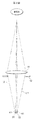
- the lights L1 and L2 from the subject that are made into parallel light are split left and right by mirrors 151 and 161.
- the light L1 on the right side toward the subject is reflected by the mirrors 151 and 152 and enters the imaging lens 153.
- the right light L 1 incident on the imaging lens 153 forms an image on the light receiving surface of the image sensor 154.
- an image from the viewpoint of the right eye is obtained.
- the light L2 on the left side toward the subject is reflected by the mirrors 161 and 162 and enters the imaging lens 163.
- the left light L2 incident on the imaging lens 163 forms an image on the light receiving surface of the image sensor 164.
- an image from the viewpoint of the left eye is obtained.
- Left and right parallax images can be obtained.
- An imaging apparatus that acquires left and right parallax images in this way is disclosed in Japanese Patent Application Laid-Open No. 2010-81580.
- the depth information generation unit uses the left-eye viewing image and the right-eye viewing image from the left-eye viewing image and the right-eye viewing image for displaying the generated stereoscopic image. Generate a depth map for each of the images.
- An imaging apparatus and an imaging method for creating a parallax map from a parallax image are disclosed in JP 2008-116309 A, JP 2008-141666 A, JP 2009-14445 A, and JP 2010-226500 A. ing.
- Japanese Patent Application Laid-Open Nos. 2003-7994, 2001-12916, and 2001-16611 disclose a three-dimensional image that can output a plurality of images having phase differences by pupil division with respect to a light beam from a single imaging optical system.
- an imaging device For example, in Japanese Patent Application Laid-Open No. 2003-7994, a solid-state image sensor that generates an image signal by photoelectrically converting a subject image formed on the imaging surface by arranging a large number of pixels on the same imaging surface.
- a solid-state imaging device is disclosed in which the pixels are divided into two groups, and the light receiving incident angles of the pixels in each group are different from each other.
- JP 2003-7994 A, JP 2001-12916 A, and JP 2001-16611 A there is a phase difference due to pupil division with respect to a light beam from a single imaging optical system (different viewpoints).
- a part of the pixels of the image sensor is used for the left parallax image output, and the remaining part is used for the right image output.
- phase difference pixels pixels that output left and right parallax
- the number of horizontal pixels that can be used for the left and right parallax images is as follows: Therefore, the number of pixels that do not have a pixel that outputs parallax is half the original number.
- the horizontal resolution is half that of an output two-dimensional image from an original image sensor having no phase difference pixels.
- the resolution corresponding to the number of pixels of each image sensor can be obtained.
- the parallel imaging system (not shown) and the mirrors 151, 152, 153, 154, and the two image pickup devices 156 and 164 are necessary, so that the cost disadvantage cannot be avoided.
- An object of the present invention is to enable stereoscopic imaging without sacrificing resolution in a stereoscopic imaging apparatus that outputs image data representing a plurality of images having different viewpoints by pupil division.
- a stereoscopic imaging device according to the present invention is provided in front of a light receiving surface of a solid-state electronic imaging device and solid-state electronic imaging device that outputs image data representing a plurality of images having different viewpoints by pupil division, and the light-receiving surface of the solid-state electronic imaging device.
- Disparity information calculating means for calculating disparity information of a plurality of images using image data representing a plurality of images, at the second time point Generated by a plane image data generation unit (planar image data generation device) for generating plane image data representing a plane image from image data representing a plurality of images output from the solid-state electronic imaging device, and the parallax information calculation unit.
- the apparatus includes a recording control unit (recording control device) that records the parallax information and the planar image data generated by the planar image data generation unit on a recording medium.
- the present invention also provides a stereoscopic imaging method suitable for the stereoscopic imaging apparatus.
- the solid-state electronic imaging device outputs image data representing a plurality of images having different viewpoints by pupil division, and a diaphragm is provided in front of the light receiving surface of the solid-state electronic imaging device.
- the amount of the light beam incident on the light receiving surface is adjusted so that the aperture control device has an open amount that causes parallax in a plurality of images represented by the image data output from the solid-state electronic imaging device at the first time point.
- the aperture is controlled, and the aperture is controlled so that the amount of passing light is smaller than the aperture at the first time point at the second time point.
- the parallax information of the plurality of images is calculated using the image data representing the plurality of images output from the solid-state electronic imaging device at the time, and the planar image data generating means Then, plane image data representing a plane image is generated from image data representing a plurality of images output from the solid-state electronic imaging device, and the recording control means generates the parallax information and the plane image data generated by the parallax information calculation means.
- the planar image data generated by the generating means is recorded on a recording medium. According to the present invention, image data representing a plurality of images with different viewpoints by pupil division is output from the solid-state electronic imaging device.
- the aperture is controlled so as to have an open amount in which parallax occurs in a plurality of images represented by image data output from the solid-state electronic imaging device.
- Disparity information of a plurality of images is calculated using image data representing a plurality of images output from the solid-state electronic imaging device at the first time point.
- the aperture is controlled so that the opening amount is smaller than the opening amount at the first time point.
- Planar image data representing a planar image is generated from image data representing a plurality of images output from the solid-state electronic imaging device at the second time point.
- the calculated parallax information and the generated planar image data are recorded on a recording medium.
- the opening amount of the diaphragm increases so as to increase the amount of light passing through, a parallax amount between a plurality of images represented by image data obtained in the solid-state electronic imaging device is generated.
- the aperture opening amount is reduced so that the amount of light passing through is reduced, the amount of parallax between a plurality of images represented by the image data obtained in the solid-state electronic imaging device is reduced. Since the aperture is controlled so that the amount of parallax is generated at the first time point, the amount of parallax between a plurality of images represented by the image data obtained from the solid-state electronic imaging device at the first time point can be calculated.
- the aperture is controlled so that the amount of passing light is less than at the first time point, so that a plurality of images substantially free of parallax can be obtained. Since a planar image is generated from a plurality of images having substantially no parallax, the resolution of the generated planar image is increased. When a stereoscopic image that can be stereoscopically viewed is generated from a high-resolution planar image and the calculated parallax information, a high-resolution stereoscopic image can be obtained.
- Stereoscopic image data generating means for generating stereoscopic image data representing a stereoscopically viewable stereoscopic image from the planar image data generated by the planar image data generating means and the parallax information calculated by the parallax information calculating means.
- a data generation device the recording control unit records, for example, the stereoscopic image data generated by the stereoscopic image data generating unit on a recording medium instead of the planar image data and the parallax information, or the plane image data and In addition to the parallax information, the stereoscopic image data generated by the stereoscopic image data generating means is recorded on a recording medium.
- the stereoscopic image data generation means includes a planar image represented by the planar image data generated by the planar image data generation means from the parallax information calculated by the parallax information calculation means, and is included in the planar image from the stereoscopic imaging device.
- You may provide the distance information calculation means (distance information calculation device) which calculates the distance information to a to-be-photographed object.
- stereoscopic image data can be generated from the distance information calculated by the distance information calculating means and the flat image data generated by the flat image data generating means.
- the stereoscopic image data generation means may include distance information correction means (distance information correction device) that corrects distance information about the planar image calculated by the distance information calculation means.
- stereoscopic image data can be generated from the distance information corrected by the distance information correcting unit and the plane image data generated by the plane image data generating unit.
- the stereoscopic image data generation means performs a blurring process for blurring a region representing a subject portion that is a predetermined distance away from the focused subject portion in the planar image generated by the planar image data generation portion.
- Processing means may be provided.
- the stereoscopic image data is generated from the planar image data representing the planar image subjected to the blurring process by the blurring processing unit and the distance information calculated by the distance calculating unit.
- the blur processing unit may perform blur processing on an area specified by the user in the planar image.
- the second time point is, for example, a time point when an instruction to capture a planar image is input by the user, and the first time point is a time point before or after the second time point.
- the aperture control device may control an opening amount of the aperture so that parallax does not occur in a plurality of images represented by image data output from the solid-state electronic imaging device at a second time point.
- FIG. 1 shows the light receiving surface of the image sensor.
- FIG. 2 shows a state in which light enters the photoelectric conversion element.
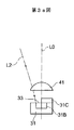
- FIGS. 3a and 3b show how light enters the photoelectric conversion element.
- FIG. 4a shows a photoelectric conversion element representing a left viewpoint image
- FIG. 4b shows a photoelectric conversion element representing a right viewpoint image.
- FIG. 5 shows a state in which light enters the photoelectric conversion element.
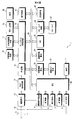
- FIG. 6 is a block diagram showing an electrical configuration showing an electrical configuration of the stereoscopic imaging apparatus.
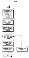
- 7 and 8 are flowcharts showing the processing procedure of the stereoscopic imaging apparatus.
- FIG. 9a shows the left viewpoint image
- FIG. 9b shows the right viewpoint image.
- FIG. 10 shows a parallax map.
- FIG. 10 shows a parallax map.
- FIG. 11a shows the light receiving surface of the image sensor
- FIG. 11b shows the photoelectric conversion element representing the left viewpoint image
- FIG. 11c shows the right viewpoint image.
- FIG. 12 is a flowchart showing a distance map creation processing procedure.
- FIG. 13 is a flowchart showing the blur processing procedure.
- FIG. 14 shows how a plurality of images can be obtained by conventional pupil division.
- FIG. 1 shows a part of the light receiving surface of the image sensor 13 used in the stereoscopic imaging apparatus according to this embodiment.
- a large number of photoelectric conversion elements 31 and 32 are provided on the light receiving surface in the column direction and the row direction.
- the odd-numbered photoelectric conversion elements are denoted by reference numeral 31, and the even-numbered photoelectric conversion elements are denoted by reference numeral 32.
- the odd-numbered photoelectric conversion elements 31 and the even-numbered photoelectric conversion elements 32 are shifted by 1/2 of the photoelectric conversion elements 31 or 32 in the column direction.
- a red filter that transmits a red light component (indicated by symbol R), a green filter that transmits a green light component (indicated by symbol G), or a blue light component.
- a blue filter (indicated by reference symbol B) is transmitted.
- Green filters G and red filters R are alternately formed in the column direction on the light receiving surfaces of the photoelectric conversion elements 31 in the 4n + 1 (n is 0 or positive integer) rows and the photoelectric conversion elements 32 in the 4n + 2 rows.
- Blue filters B and green filters G are alternately formed in the column direction on the light receiving surfaces of the photoelectric conversion elements 31 in the 4n + 3 rows and the photoelectric conversion elements 32 in the 4n + 4 rows.
- the light receiving surfaces of the photoelectric conversion elements 31 and 32 are roughly divided into two on the left and right.
- the right side of the light receiving surface of the odd-numbered photoelectric conversion elements 31 is shielded from light, and the left side is opened so that light can be received.
- the light receiving surfaces of the photoelectric conversion elements 32 in even rows are shielded on the left side and opened so that the right side can receive light.
- the green filter G formed in the opening as described above is indicated by the black paint 33
- the red filter R is indicated by the stripe pattern 34
- the blue filter B is indicated by the white 35. It is shown in FIG.
- FIG. 2 shows a state in which the odd-numbered photoelectric conversion elements 31 and the even-numbered photoelectric conversion elements 32 are taken out one by one, and light beams representing a subject image are incident on the photoelectric conversion elements 31 and 32.
- . 3a is an enlarged view of the vicinity of the photoelectric conversion element 31 compared to FIG. 2
- FIG. 3b is an enlarged view of the vicinity of the photoelectric conversion element 32 compared to FIG.
- Both the light beam L1 from the right side of the subject and the light beam L2 from the left side of the subject pass through the imaging lens 11 and the stop 12.
- a micro lens 41 is disposed in front of the light receiving surfaces of the photoelectric conversion elements 31 and 32. Referring to FIG.
- the light shielding member 31C is provided on the right side of the light receiving surface 31B of the odd-numbered photoelectric conversion elements 31 as described above.
- the left side of the light receiving surface 31B becomes the opening 33 (34, 35).
- the light beam L2 from the left side of the subject enters the photoelectric conversion element 31.
- the light shielding member 32C is provided on the left side of the light receiving surface 32B of the even number of photoelectric conversion elements 32.
- the right side of the light receiving surface 32B is an opening 33 (34, 35).
- the light beam L1 from the right side of the subject enters the photoelectric conversion element 32.
- FIG. 4a shows a state where the odd-numbered photoelectric conversion elements 31 are extracted from the image sensor 13, and FIG. 4b shows a state where the even-numbered photoelectric conversion elements 32 are extracted from the image sensor 13.
- the right side of the light receiving surface is shielded and the left side is opened as described above.
- FIG. 5 corresponds to FIG. 2 and shows a state where a light beam representing a subject image is incident on the photoelectric conversion elements 31 and 32.
- the aperture is made small so that the aperture amount of the diaphragm 12 is smaller than the aperture amount of the diaphragm 12 shown in FIG.
- the aperture amount of the stop 12 is reduced, both the amount of light beams incident on the odd-numbered photoelectric conversion elements 31 and the amount of light beams incident on the even-numbered photoelectric conversion elements 32 are reduced.
- the parallax between the left viewpoint image and the right viewpoint image is reduced, and two images having substantially no parallax can be obtained.
- a plane image with high resolution can be obtained. For example, two images that are substantially free of parallax can be obtained by shooting with the aperture 12 down to the minimum aperture F11.
- a high-resolution planar image can be obtained from two images by reducing the aperture amount of the diaphragm 12, and a left viewpoint image and a right viewpoint with parallax can be obtained by increasing the aperture amount of the aperture 12.
- An image is obtained.
- a parallax map representing the amount of parallax in the corresponding pixels of the pixels constituting the left viewpoint image and the pixels constituting the right viewpoint image is created from the left viewpoint image and the right viewpoint image having parallax. Is done.
- a high-resolution stereoscopic image is obtained from the created parallax map and the high-resolution planar image.
- the image sensor 13 described above is a single image sensor 13, but it may be a plurality of image sensors including an image sensor having the structure shown in FIG. 4a and an image sensor having the structure shown in FIG. 4b.
- an image sensor having a larger number of pixels can be used, and a general-purpose Bayer can be used as shown in FIGS. 4a and 4b.
- An image sensor having an array filter can be used.
- the optical system requires a mirror as shown in FIG. 14, but a high-resolution stereoscopic image can be obtained as compared with a conventional stereoscopic imaging apparatus.
- FIG. 6 is a block diagram showing an electrical configuration of the stereoscopic imaging apparatus 1.
- the stereoscopic imaging apparatus 1 records image data representing an image represented by imaging in a memory 25 including a memory card 27 or a built-in memory.
- the overall operation of the stereoscopic imaging apparatus 1 is controlled by a CPU (central processing unit) 10.
- Each part is provided with an auxiliary control device, and the load on the CPU 10 is reduced by these auxiliary control devices.
- the image sensor control device 6 controls the image sensor 13.
- the CPU 10 performs overall control without an auxiliary control device.
- the memory card 27 includes the memory card control device 26
- the memory card control device 26 itself may not exist independently. Thus, there is a possibility that the configuration of FIG. 6 can be changed as appropriate.
- the stereoscopic imaging apparatus 1 is provided with operation devices 7 such as a release switch, a shooting / playback switch, and a shooting mode change dial.
- the release switch is an operation switch for inputting a photographing start instruction, and is a two-stage stroke type having an S1 switch that is turned on when half-pressed and an S2 switch that is turned on when fully pressed.
- the shooting / playback switch is for switching between a shooting operation and a playback operation for displaying on the display device 20 a still image or a moving image of a stereoscopic image (3D image) or a planar image (2D image) recorded by the shooting operation.
- the shooting mode change dial is a dial for selecting various shooting modes for shooting still images and moving images of stereoscopic images or planar images.
- the operation device 7 includes other switches for inputting various instructions to the stereoscopic imaging device 1. These switches, dials and the like are not only mechanical switches, but may be configured as a touch panel on the display screen of the display device 20, for example.
- An operation signal output from the operation device 7 is input to the CPU 10, and the CPU 10 controls each part of the stereoscopic imaging device 1 based on the operation signal.
- the control program is recorded in the memory 25.
- various data necessary for control executed by the CPU 10 various information about the image sensor 13, parameters related to the operation of the stereoscopic imaging device 1, and the like are recorded in the memory 25.
- the memory unit 25 does not need to be composed of a single memory, but can be composed of DRAM (dynamic random access memory), flash memory, VRAM (video random access memory), or the like as necessary. .
- An imaging lens 11 and a diaphragm 12 are provided in front of the light receiving surface of the imaging element 13.
- the diaphragm 12 has a role of changing the amount of the light beam L and regulating the width of the light beam L.
- the diaphragm 12 includes a plurality of diaphragm blades and a group of diaphragm holes having different diaphragm systems, and is controlled by the diaphragm control device 4. For example, the aperture value (F value) F2.8 to F11 is controlled in five steps in increments of 1AV.
- the imaging lens 12 is subjected to focus control, zoom control, and the like by the lens control device 2.
- the light beam L from the subject passes through the imaging lens 11 and the diaphragm 12 and forms an image on the light receiving surface of the imaging element 13 described above.
- Examples of the image pickup device 13 include a CMOS image pickup device, a CCD image pickup device, and the like, but the type of these image pickup devices is not limited.
- the image sensor control device 6 performs drive control, read control, and the like of the image sensor 13. When the shooting mode is set, the subject is imaged by the image sensor 13. A video signal representing a subject image is output from the image sensor 13. As described above, the image sensor 13 according to this embodiment can capture two subject images having different viewpoints.
- the video signals representing the two subject images are subjected to predetermined analog signal processing such as amplification in an analog signal processing device 14 (which is not necessarily required depending on the type of the image sensor). If the image sensor 13 is a CCD, analog signal processing such as correlated double sampling is also performed. When the image sensor 13 is a CMOS image sensor, an analog signal processing circuit corresponding to the CMOS image sensor and the AD converter 15 are generally built in the image sensor 13. The video signal output from the analog signal processing device 14 is converted into digital image data in an AD (analog / digital) conversion device 15. The converted digital image data is input to the AF control device 3.
- AD analog / digital
- the AF control unit 3 extracts high-frequency components of image data in a predetermined focus area (such as the central area of the screen) from the image data, and integrates the extracted high-frequency components to indicate an AF evaluation indicating the in-focus state. A value is calculated. AF control is performed by controlling the focus lens in the imaging lens 11 with the lens control device 2 so that the AF evaluation value is maximized (contrast autofocus processing).
- phase difference autofocus processing is performed using image data representing two subject images with different viewpoints, a graph representing the integrated value of the image data representing the subject image from one viewpoint and the other viewpoint A defocus amount is obtained based on information indicating a phase difference from a graph representing an integral value of image data representing a subject image.
- the focus position of the imaging lens 11 is controlled so that the defocus amount becomes zero.
- the converted digital image data is also input to the AE control device 5.
- the shutter speed of the image sensor 13 (so-called electronic shutter speed) is determined.
- an auxiliary light emitting device or the like controlled by the auxiliary light control device may be provided, or the external auxiliary light device may be controlled by the CPU 10 and the AE control device 5.
- the digital image data is input to the display control device 21 via the bus 29. By controlling the display device 20 in the display control device 21, the captured subject image is displayed on the display screen of the display device 20.
- a stereoscopic image can be displayed as a directional image having a predetermined directivity by a parallax barrier, or a display device 20 can be displayed using a lenticular lens.
- a planar image can be displayed on the display screen of the display device 20 as described later, and a stereoscopic image can also be displayed.
- the release switch is pressed halfway (for example, at a first time)
- the diaphragm 12 is opened.
- image data representing two subject images having parallax and having different viewpoints can be obtained.
- These image data are input to the digital signal processing device 19, and predetermined digital signal processing such as various correction processing, amplification processing such as white balance adjustment, and gamma correction processing is performed.
- the image data output from the digital signal processing device 19 is input to the parallax information calculation device 22.
- the parallax information calculation device 22 calculates the parallax for each pixel constituting two subject images having different viewpoints.
- Information representing the calculated parallax is input to the parallax map creation device 23, and a parallax map is created.
- the diaphragm 12 is set to the small diaphragm side where the amount of light passing therethrough is reduced.
- Image data representing two subject images that are substantially free of parallax (with substantially the same viewpoint) can be obtained.
- image data representing a planar image representing one subject image is created from image data representing two subject images.
- the data representing the parallax map created by the parallax map creating device 23 and the image data representing the planar image created by the planar image creating device 16 are input to the stereoscopic image creating device 17 and image data representing the stereoscopic image (planar) This is data in which a parallax map is added to image data, and a stereoscopic image is generated from planar image data and a parallax map).
- the created image data representing the stereoscopic image is compressed by the compression / decompression device 28 (for example, planar image data is compressed based on JPEG).
- Image data representing the compressed stereoscopic image is recorded on the memory card 27 under the control of the memory card control device 26.
- RAW image data that is not necessarily compressed but not compressed may be recorded on the memory card 27.
- the stereoscopic imaging apparatus includes a distance information calculation device 24 and a blur processing device 18.
- the distance information calculation device 24 calculates distance information from the parallax map created by the parallax map creation device 23. The portion where the parallax is 0 is considered to represent the subject image at the in-focus position of the imaging lens 12.
- the focused portion of the two pupil-divided images forms an image at the same position on the image sensor 13, that is, a point that coincides in two images having different viewpoints.
- the portion of the image representing the subject that is closer to the stereoscopic imaging device 1 than the in-focus position has a coincidence point farther away than the position of the image sensor 13 and is separated with non-focus blur.
- an image portion farther than the in-focus position has a coincidence point ahead of the position of the image sensor 13 and therefore is separated with non-focus blur, and for an image closer to the stereoscopic imaging apparatus 1 than the in-focus position.
- the left and right positions are inverted and separated.
- the left and right viewpoint image data and the plane image are input to the stereoscopic image creation device 17, the corresponding points of both images in the left and right viewpoint image data and the plane image data are detected, and are associated with the left and right viewpoint image data.
- the parallax information or the distance information is associated with the planar image data. Since the corresponding points are already detected from the left and right viewpoint image data, it is efficient to detect the already detected corresponding points from the planar image data.
- Corresponding point detection is performed between the left viewpoint image data and the plane image data, and between the right viewpoint image data and the plane image data. The reason why the viewpoint image data and the plane image data are set is that the plane image data has corresponding points that correspond only to the left or right viewpoint image data.
- the common corresponding point detection itself can be simultaneously performed from three image data between the left and right viewpoint image data and the planar image data. Furthermore, only corresponding point detection can be performed independently by providing a corresponding point detection unit (not shown), or the CPU 10 can perform corresponding point detection processing.
- the reproduction mode is set, the image data recorded on the memory card 27 is read and given to the display device 20.
- the stereoscopic image data is given to the display device 20, the stereoscopic image is displayed on the display screen of the display device 20.
- the plane image data is given to the display device 20, the plane image is displayed on the display screen of the display device 20.
- the created stereoscopic image can be said to be a planar image having distance (depth) information.
- the left and right viewpoint image data and the planar image data have different data amounts as described above, it is desirable that the data amounts (number of pixels) be made uniform in order to perform corresponding point detection at a higher speed. If a parallax map or distance map corresponding to the left and right viewpoint image data has already been created by the parallax map creating device 23, the corresponding point between the left and right viewpoint image data and the planar image data is further determined by the parallax map creating device 23.
- the parallax map or the distance map corresponding to the planar image data can be created and used as stereoscopic image data.
- the stereoscopic image data is basically planar image data because the distance or parallax data or the distance or parallax map (hereinafter referred to as incidental parallax information) corresponds to the planar image data.
- the planar image data is an image close to a so-called omnifocal image that is focused from the front to the back of the subject on which the imaging lens 11 is focused because the aperture 12 is set to the minimum aperture at the time of shooting. .
- the blur processing is further performed using the blur processing device 18.
- the blur processing device 18 Since the natural stereoscopic image data can be obtained by blurring a subject with a large parallax or a distance away from the focal position, the blur processing device 18 has a large parallax or a distance from the focal position based on the incidental parallax information.
- the blur amount is determined so as to blur the image data as the distance increases, and the planar image data is blurred.
- the blur amount may be determined from the image in the blur processing device 18, or the user may be able to input the maximum blur amount or the aperture value (F value) corresponding to the blur amount. User preferences can be reflected.
- the stereoscopic image data is data in which distance information (parallax map) is added to a planar image when the subject is viewed almost from the front, depending on how the display control unit adds parallax, it is blocked by the object in front.
- An occlusion area which is an area in which the object is invisible, is generated.
- the planar image data corresponds to one or both of the left and right viewpoint image data at the corresponding points. Therefore, although it does not exist in the plane image data, the display control device 21 can interpolate a region where the image data is included in either the left or right parallax image data. Thereby, loss of stereoscopic image data can be prevented.
- the blur processing device 18 when used to blur the planar image data in the stereoscopic image data, the blur processing is also extended to the occlusion area, for example, the in-focus position distance and a predetermined distance before and after the focus position distance.
- Blur image data can be created for each range, and the occlusion area can be interpolated by using the blur image data.
- a more natural stereoscopic image can be displayed.
- the stereoscopic image data recorded on the memory card 27 or the like may be image data composed of information on a parallax or distance or a map thereof as described above, or image data for display created by the display control device 21. (For example, two parallax images having left and right parallaxes) may be used.
- FIGS. 7 and 8 are flowcharts showing the processing procedure of the stereoscopic imaging apparatus 1. This process starts when the shooting mode is set to “stereoscopic shooting” and a shooting instruction is given.
- the CPU 10 determines whether the left and right viewpoint images are shot first or the planar image is shot first (step 41). Which is to be performed first is set in advance by the user and recorded in the memory 25. If it is determined that the left and right viewpoint images have been captured first (YES in step 41), the CPU 10 at the first time point (may be when the release switch is half-pressed or not half-pressed as described above).
- a diaphragm for photographing the left and right viewpoint images that is, an optimum diaphragm value for obtaining the parallax for the left and right viewpoints (a diaphragm value that increases the aperture as shown in FIG.
- the diaphragm 12 is controlled so as to be a value (step 42).
- Shooting (shooting at the first time point) is performed by performing AE control, AF control, and the like.
- the CPU 10 controls the image sensor control device 6 and reads out video signals of the left viewpoint and the right viewpoint from the image sensor 13. Left and right viewpoint image data are created from the left and right viewpoint video signals (step 43). Subsequently, at the second time point (when the release switch is fully pressed or not fully pressed as described above), the CPU 10 is a diaphragm for photographing a plane image, that is, an optimum diaphragm for reducing parallax as much as possible.
- a value (aperture value that reduces the aperture amount as shown in FIG. 5) is determined, and the aperture 12 is controlled to be the determined aperture value.
- Shooting (shooting at the second time point) is performed by performing AE control, AF control, and the like (step 44).
- the CPU 10 controls the image sensor control device 6 and reads a video signal for a planar image from the image sensor 13.
- Planar image data is created by controlling the digital signal processing device 19 and the like from the video signal for the planar image (step 45). If the left and right viewpoint images are not captured first (NO in step 41), the CPU 10 determines the aperture value for planar image capturing at the first time point, and the aperture 12 is set to the determined aperture value. It is set (step 47).
- Photographing (photographing at the first time point) is performed after AE control, AF control, and the like are performed.
- the CPU 10 controls the image sensor control device 6, reads a video signal for a plane image from the image sensor 13, and creates plane image data by controlling the digital signal processing device 19 and the like (step 48). Subsequently, at a second time, the CPU 10 determines an aperture value for photographing the left and right viewpoint images, and controls the aperture 12 so as to be the aperture value (step 49). After AE control, AF control, etc. are performed, photographing (photographing at the second time point) is performed. The CPU 10 controls the image sensor control device 6 to read out the video signals of the left viewpoint and the right viewpoint from the image sensor 13 and create left and right viewpoint image data (step 50).
- FIG. 9a is an example of the left viewpoint image 61 represented by the left viewpoint image data
- FIG. 9b is an example of the right viewpoint image 62 represented by the right viewpoint image data.
- corresponding points that are pixels corresponding to the respective pixels constituting the left viewpoint image 61 are detected from the right viewpoint image 62. Only a small number of corresponding points shown in the right viewpoint image 62 are shown for easy understanding, but it goes without saying that more corresponding points are detected.
- FIG. 10 is an example of the created parallax map 63.
- the parallax map 63 includes a region 63A (illustrated by cross-hatching) where the parallax is 0, a region 63B (illustrated by hatching) where the parallax is small, and a region 63C (not hatched) where the parallax is medium )It is included.
- the parallax map 63 is divided into three regions having different parallax amounts, but it goes without saying that the parallax information for each pixel is calculated. Therefore, in practice, continuous disparity information is expressed two-dimensionally as a disparity map.
- a parallax map corresponding to planar image data is created by interpolating from parallax information associated with surrounding corresponding points.
- a distance map is created from the parallax map associated with the planar image data and the focal length of the focusing position of the imaging lens 11 (step 52 in FIG. 8). For example, as shown in FIG.
- a distance map is created in which the area 63A is close, the area 63B is medium, and the area 63C is far.
- the distance is calculated corresponding to the pixels constituting the planar image in the distance map.
- stereoscopic image data representing a stereoscopic image is created from the planar image data and the distance map (step 53 in FIG. 8).
- a stereoscopic image is created using the distance map.
- stereoscopic image data can be created using the parallax map without creating a distance map.
- the disparity information (disparity map) is a relative value from the in-focus position, whereas the distance information (distance information) is only a difference.
- the stereoscopic image two images having left and right parallax can be created, and the two images can be displayed by controlling the display control device 21 and using the display device 20. If there is information to be recorded (eg, parallax information) in addition to the stereoscopic image data (YES in step 54), information to be recorded in addition to the stereoscopic image data is selected (step 55).
- the contents of the information to be selected may be selected in advance by the user and recorded in the memory 25, or may be selected by the user during recording.
- the selected information is recorded in the data recording area of the memory 25 together with the stereoscopic image data, or is recorded on the memory card 27 by controlling the memory card control device 26 (step 56). If it is determined that there is no information to be recorded in addition to the stereoscopic image data (NO in step 54), the stereoscopic image data is recorded on the memory card 27 or the like without recording other information ( Step 57). It may be possible to record other information (such as only the plane image and the parallax information) without recording the stereoscopic image data.
- the above is an example of stereoscopic still image shooting, but it can also be applied to stereoscopic moving images.
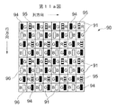
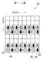
- FIGS. 11a, 11b and 11c show a modification.
- 11a corresponds to FIG. 1 and shows the light receiving surface of the image sensor 90.
- FIG. 11b corresponds to FIG. 4a and shows a photoelectric conversion element representing the left viewpoint image.
- the figure corresponds to FIG. 4b and shows a photoelectric conversion element representing a right viewpoint image.
- the image sensor 90 has a large number of photoelectric conversion elements 91 arranged in the column direction and the row direction.
- the photoelectric conversion elements 91 in the 4n + 1th row and the 4n + 2th row the right side of the light receiving region is shielded from light and the left side of the light receiving region is opened.
- the photoelectric conversion elements 91 in the 4n + 3 row and the 4n + 4 row the left side of the light receiving region is shielded from light, and the right side of the light receiving region is opened.
- a filter B is formed.
- the green filter G is illustrated with a black reference numeral 94
- the red filter R is illustrated with a striped reference numeral 95
- the blue filter B is illustrated with a white reference numeral 96.
- These filter arrays are so-called Bayer arrays.
- the photoelectric conversion elements 91 in the 4n + 1 row and the 4n + 2 row are extracted when the photoelectric conversion elements 91 in the 4n + 1 row and the 4n + 2 row are extracted as shown in FIG.
- the image obtained based on the photoelectric conversion element 91 represents the left viewpoint image.
- the photoelectric conversion elements 91 in the 4n + 3 row and the 4n + 4 row are extracted when the photoelectric conversion elements 91 in the 4n + 3 row and the 4n + 4 row are extracted as shown in FIG. 11c because the left side of the light receiving region is shielded from light.
- the image obtained based on the photoelectric conversion element 91 represents a right viewpoint image.
- Two image sensors, that is, the image sensor having the structure shown in FIG. 11b and the image sensor having the structure shown in FIG. 11c may be used.
- a left-view subject image and a right-view subject image are obtained by shielding the left or right side of the light-receiving surface of each photoelectric conversion element 91.
- Left and right 1/4, left side 1/4 to 1/2, left side 1/2 to 3/4, right side 1/4, and the image sensor 90 is configured to be shielded or opened so that the viewpoint is different. Image data representing four images is obtained. Similarly, the number of viewpoints can be further increased.
- the optical axis of the micro lens 41 coincides with the center of the light receiving region, but it does not necessarily have to coincide. Even if the optical axis of the micro lens 41 is deviated from the center of the light receiving region, the light beam incident on the light receiving region may be limited. Further, by providing one micro lens 41 for adjacent two or four photoelectric conversion elements, the light flux incident on each photoelectric conversion element may be limited.
- FIG. 12 shows a modification and is a flowchart showing a distance map creation processing procedure (processing procedure of step 52 in FIG. 8).
- the stereoscopic image data created by the stereoscopic imaging apparatus 1 is composed of planar image data and a distance map. Since the parallax information is unique to the imaging device, the distance calculated from the parallax is the distance between the stereoscopic imaging device and the subject at the time of shooting. When a relatively distant subject is photographed as the main subject, the distance difference between the main subject and the background is small, and the stereoscopic effect of the stereoscopic image displayed by the generated stereoscopic image data may be insufficient. In this modification, distance emphasis processing (distance correction processing) can be performed.
- the distance between the main subject and the background is small, and when there are no other subjects, the stereoscopic effect of the entire stereoscopic image is insufficient. It is desirable to perform processing for emphasizing the difference in distance (distance difference). In addition, when the distance between the background and the main subject is short, it is also desirable to perform a process of increasing the distance (moving far) only in the background. In addition, when it is desired to enhance the stereoscopic effect of a subject at a specific distance in the stereoscopic image, the user can specify and enhance the stereoscopic effect. Distance emphasis is combined with distance emphasis and is called distance emphasis. A determination is made as to whether there is a user designation for distance enhancement processing (step 101).
- step 101 it is determined whether there is a designation of an emphasis distance range designated by the user (step 102).
- the enhancement distance range designated by the user is designated (YES in step 102)
- the distance information in the designated distance range is designated as the enhancement distance region (step 103).
- step 104 it is determined whether or not there is an enhancement degree designation for distance enhancement (step 104). If there is an enhancement degree designation for distance enhancement (YES in step 104), the designated distance range is enhanced with the designated enhancement degree, and a distance map is recreated (step 106).
- the enhancement distance region and the enhancement degree are determined with reference to the distance map.
- the distance distribution calculated from the distance map is compared with the distance distribution of standard stereoscopic image data, and the emphasis distance and the emphasis degree are determined.
- the determined distance range is emphasized with the determined enhancement degree, and a distance map is re-created (step 106).
- the enhancement degree is not specified (NO in step 104)
- the enhancement distance range calculated from the distance map and the entire distance distribution are compared with the distance distribution of the standard stereoscopic image data to determine the enhancement degree.
- a distance map emphasized with an emphasis degree determined by the already specified emphasis distance range is re-created (step 107).
- the distance range is determined with reference to the distance map (step 108), and the distance map is recreated with the determined distance range emphasized with the determined degree of enhancement. (Step 109).
- the distance map and the planar image data recreated in this way are recorded in the memory card 27 or the like as stereoscopic image data.
- left viewpoint image data and right viewpoint image data are created from the recreated distance map and plane image data, and the created left viewpoint image data and right viewpoint image data are used as stereoscopic image data as a memory card. 27 may be recorded.
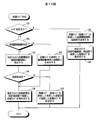
- FIG. 13 is a flowchart showing the blur processing procedure, showing another modification.
- stereoscopic image data created by the stereoscopic imaging device is based on planar image data and a distance map.
- the stereoscopic image represented by the stereoscopic image data is image data that is close to the so-called omnifocal image and is in focus from the near side to the back side in order to reduce the aperture 12.
- “blurring” is an important factor when a human is stereoscopically viewing, and a stereoscopic effect can be felt even when a subject other than the focused subject is blurred.
- the left and right viewpoint images represented by the left and right viewpoint image data have a large parallax (from the in-focus distance) because the diaphragm 12 is opened when the left and right parallax images are captured.
- the subject is far away. Since the stereoscopic image represented by the stereoscopic image data that can be acquired by the stereoscopic imaging apparatus of this embodiment is close to the omnifocal image as described above, the left and right viewpoint images represented by the left and right viewpoint image data. As described above, a more natural stereoscopic image can be obtained by blurring a subject image that is far from the in-focus distance.
- the process shown in FIG. 13 is performed between step 52 and step 53 in FIG.
- step 131 it is determined whether or not there is a user designation regarding the blurring process (step 131). If there is a user designation (YES in step 131), it is determined whether or not a blur distance range designated by the user is designated (step 132). If the blur distance range designated by the user is designated (YES in step 131), the area of the planar image data corresponding to the designated blur distance range of the distance map is designated as the blur area (step 133). When the blur distance range designated by the user is not designated (NO in step 131), the distance map is referred to determine the blur distance area and the enhancement degree (step 138). For example, referring to the distance map, processing such as setting a subject that is a fixed distance away from the focused main subject as a blur region is performed.
- a blur parameter is specified (step 135).
- the blur process is performed with the blur parameter designated by the designated blur distance range of the stereoscopic image data (step 136). If no blur parameter is specified (NO in step 135).
- the blur parameter is determined by referring to the distance map of the designated or determined blur region (step 137). For example, the blurring parameter is determined by making the intensity of blurring proportional to the function of distance.
- the specified blur distance range of the stereoscopic image data is subjected to the blur process with the specified blur parameter. If there is no user designation (NO in step 131), the distance map is referred to determine the blur distance range and blur parameter (step 138).
- the determined blur distance range is subjected to blur processing with the determined blur parameter (step 139).
- the planar image data and the distance map subjected to the blurring process in this way are recorded in the memory card 27 as stereoscopic image data.
- left viewpoint image data and right viewpoint image data are created from the planar image data and the distance map subjected to the blurring process, and the created left viewpoint image data and right viewpoint image data are recorded in the memory card 27. You may make it do.
Landscapes
- Engineering & Computer Science (AREA)
- Multimedia (AREA)
- Signal Processing (AREA)
- Physics & Mathematics (AREA)
- General Physics & Mathematics (AREA)
- Spectroscopy & Molecular Physics (AREA)
- Testing, Inspecting, Measuring Of Stereoscopic Televisions And Televisions (AREA)
- Stereoscopic And Panoramic Photography (AREA)
Abstract
瞳分割により視点の異なる複数の画像を出力可能な撮像装置を有する立体撮像装置において,撮像素子が持つ解像度を犠牲にせず,立体撮像を行う。第1の時点で,撮像から出力される複数の画像で視差が得られるように絞りの開放量が制御されて視差画像が取得される。第2の時点で,開放量が第1の時点における絞りの開放量よりも小さくなるように絞りが制御されて平面画像が取得される。第1の時点で取得された複数の画像に基づいて視差情報が算出され,第2の時点で取得した平面画像が作成される。視差情報と平面画像とからなる立体視画像の作成が行われ,瞳分割により視点の異なる複数の画像が出力可能な撮像素子を持つ撮像装置を有する立体撮像装置において,撮像素子の全ての光電変換素子を使った解像度の立体視画像作成を行うことが出来る。
Description
この発明は,立体撮像装置および立体撮像方法に関する。
従来,撮影レンズの異なる領域を通過した被写体像をそれぞれ撮像素子に結像させ,異なる視点画像を取得する立体撮像装置が存在する。
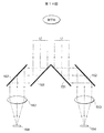
第14図に示す光学系では,平行光とされた被写体からの光L1およびL2は,ミラー151および161によって左右に分光される。被写体に向かって右側の光L1はミラー151および152において反射し,結像レンズ153に入射する。結像レンズ153に入射した右側の光L1は撮像素子154の受光面に結像する。撮像素子154において,右目の視点からの画像が得られる。同様に,被写体に向かって左側の光L2はミラー161および162において反射し,結像レンズ163に入射する。結像レンズ163に入射した左側の光L2は撮像素子164の受光面に結像する。撮像素子164において,左目の視点からの画像が得られる。左右の視差画像を得ることが出来る。このように左右の視差画像を取得する撮像装置については,特開2010−81580号公報に開示されている。
また,このような視差画像から,奥行き分布を表す視差マップを作成し,保存する技術もある。特開2011−19084号公報によると,生成された立体視画像を表示するための左眼視用画像および右眼視用画像から,奥行情報生成部が,左眼視用画像および右眼視用画像のそれぞれについて奥行マップを生成する。視差画像から視差マップを作成する撮像装置や撮像方法については,特開2008−116309号公報,特開2008−141666号公報,特開2009−14445号公報および特開2010−226500号公報に開示されている。
特開2003−7994号公報,特開2001−12916号公報および特開2001−16611号公報には単一の撮像光学系からの光束に対する瞳分割により位相差を有する複数の画像を出力可能な立体撮像装置の例が記載されている。例えば特開2003−7994号公報では,多数の画素を同一撮像面上に配列し,該撮像面に結像された被写体像を光電変換して画像信号を生成する固体撮像素子において,上記多数の画素を2つのグループに区分けし,各グループにおける画素の受光入射角度をそれぞれ異ならせてなることを特徴とする固体撮像素子が開示されている。
特開2003−7994号公報,特開2001−12916号公報および特開2001−16611号公報に記載のような,単一の撮像光学系からの光束に対する瞳分割により位相差を有する(視点の異なる)複数の画像を出力可能な立体撮像装置においては,撮像素子の画素の一部を左方向の視差の画像出力に用い,残りの一部を右方向の画像出力に用いる。正方画素配列の撮像素子に左右の視差を出力する画素(以下位相差画素)を列方向(水平方向)に均等に配置したとすると,左右のそれぞれの視差画像に用いることの出来る水平画素数は,視差を出力する画素を持たない本来の画素数の半分になってしまう。すなわち,左右の画像それぞれを単独で二次元画像として見た場合,水平解像度は位相差画素を持たない本来の撮像素子からの出力二次元画像と比べ半分になることになる。
もちろん,第14図に示すような光学系を用い撮像素子を2個設ければ,それぞれの撮像素子の画素数に応じた解像度を得ることが出来るために,解像度は犠牲とならないが,本来必要ではない平行光学系(図示略)やミラー151,152,153,154,2つの撮像素子156および164が必要であるためにコスト面での不利は免れない。
第14図に示す光学系では,平行光とされた被写体からの光L1およびL2は,ミラー151および161によって左右に分光される。被写体に向かって右側の光L1はミラー151および152において反射し,結像レンズ153に入射する。結像レンズ153に入射した右側の光L1は撮像素子154の受光面に結像する。撮像素子154において,右目の視点からの画像が得られる。同様に,被写体に向かって左側の光L2はミラー161および162において反射し,結像レンズ163に入射する。結像レンズ163に入射した左側の光L2は撮像素子164の受光面に結像する。撮像素子164において,左目の視点からの画像が得られる。左右の視差画像を得ることが出来る。このように左右の視差画像を取得する撮像装置については,特開2010−81580号公報に開示されている。
また,このような視差画像から,奥行き分布を表す視差マップを作成し,保存する技術もある。特開2011−19084号公報によると,生成された立体視画像を表示するための左眼視用画像および右眼視用画像から,奥行情報生成部が,左眼視用画像および右眼視用画像のそれぞれについて奥行マップを生成する。視差画像から視差マップを作成する撮像装置や撮像方法については,特開2008−116309号公報,特開2008−141666号公報,特開2009−14445号公報および特開2010−226500号公報に開示されている。
特開2003−7994号公報,特開2001−12916号公報および特開2001−16611号公報には単一の撮像光学系からの光束に対する瞳分割により位相差を有する複数の画像を出力可能な立体撮像装置の例が記載されている。例えば特開2003−7994号公報では,多数の画素を同一撮像面上に配列し,該撮像面に結像された被写体像を光電変換して画像信号を生成する固体撮像素子において,上記多数の画素を2つのグループに区分けし,各グループにおける画素の受光入射角度をそれぞれ異ならせてなることを特徴とする固体撮像素子が開示されている。
特開2003−7994号公報,特開2001−12916号公報および特開2001−16611号公報に記載のような,単一の撮像光学系からの光束に対する瞳分割により位相差を有する(視点の異なる)複数の画像を出力可能な立体撮像装置においては,撮像素子の画素の一部を左方向の視差の画像出力に用い,残りの一部を右方向の画像出力に用いる。正方画素配列の撮像素子に左右の視差を出力する画素(以下位相差画素)を列方向(水平方向)に均等に配置したとすると,左右のそれぞれの視差画像に用いることの出来る水平画素数は,視差を出力する画素を持たない本来の画素数の半分になってしまう。すなわち,左右の画像それぞれを単独で二次元画像として見た場合,水平解像度は位相差画素を持たない本来の撮像素子からの出力二次元画像と比べ半分になることになる。
もちろん,第14図に示すような光学系を用い撮像素子を2個設ければ,それぞれの撮像素子の画素数に応じた解像度を得ることが出来るために,解像度は犠牲とならないが,本来必要ではない平行光学系(図示略)やミラー151,152,153,154,2つの撮像素子156および164が必要であるためにコスト面での不利は免れない。
この発明は,瞳分割により複数の視点の異なる複数の画像を表す画像データを出力する立体撮像装置において,解像度を犠牲にせずに立体撮像を行うことが出来るようにすることを目的とする。
この発明による立体撮像装置は,瞳分割により視点の異なる複数の画像を表わす画像データを出力する固体電子撮像装置,上記固体電子撮像装置の受光面前方に設けられ,上記固体電子撮像装置の受光面に入射する光束の光量を調整する絞り,第1の時点で上記固体電子撮像装置から出力される画像データによって表わされる複数の画像において視差が生じる開放量となるように上記絞りを制御し,かつ第2の時点で上記第1の時点における開放量よりも通過光量が少なくなる小さい開放量となるように上記絞りを制御する絞り制御装置,上記第1の時点において上記固体電子撮像装置から出力される複数の画像を表わす画像データを用いて複数の画像の視差情報を算出する視差情報算出手段(視差情報算出デバイス),上記第2の時点において上記固体電子撮像装置から出力される複数の画像を表わす画像データから平面画像を表わす平面画像データを生成する平面画像データ生成手段(平面画像データ生成デバイス),および上記視差情報算出手段によって生成された視差情報および上記平面画像データ生成手段によって生成された平面画像データを記録媒体に記録する記録制御手段(記録制御デバイス)を備えていることを特徴とする。
この発明は,上記立体撮像装置に適した立体撮像方法も提供している。すなわち,この方法は,固体電子撮像装置が,瞳分割により視点の異なる複数の画像を表わす画像データを出力し,絞りが,上記固体電子撮像装置の受光面前方に設けられ,上記固体電子撮像装置の受光面に入射する光束の光量を調整し,絞り制御装置が,第1の時点で上記固体電子撮像装置から出力される画像データによって表わされる複数の画像において視差が生じる開放量となるように上記絞りを制御し,かつ第2の時点で上記第1の時点における開放量よりも通過光量が少なくなる小さい開放量となるように上記絞りを制御し,視差情報算出手段が,上記第1の時点において上記固体電子撮像装置から出力される複数の画像を表わす画像データを用いて複数の画像の視差情報を算出し,平面画像データ生成手段が,上記第2の時点において上記固体電子撮像装置から出力される複数の画像を表わす画像データから平面画像を表わす平面画像データを生成し,記録制御手段が,上記視差情報算出手段によって生成された視差情報および上記平面画像データ生成手段によって生成された平面画像データを記録媒体に記録するものである。
この発明によると,瞳分割により視点の異なる複数の画像を表わす画像データが固体電子撮像装置から出力される。第1の時点で,固体電子撮像装置から出力される画像データによって表わされる複数の画像において視差が生じる開放量となるように絞りが制御される。第1の時点で固体電子撮像装置から出力される複数の画像を表わす画像データを用いて複数の画像の視差情報が算出される。第2の時点では,第1の時点における開放量よりも通過光量が少なくなる小さい開放量となるように絞りが制御される。第2時点で固体電子撮像装置から出力される複数の画像を表わす画像データから平面画像を表わす平面画像データが生成される。算出された視差情報および生成された平面画像データが記録媒体に記録される。
通過光量が多くなるように絞りの開放量が大きくなると,固体電子撮像装置において得られる画像データによって表わされる複数の画像間の視差量が生じるようになる。逆に通過光量が少なくなるように絞りの開放量が小さくなると,固体電子撮像装置において得られる画像データによって表わされる複数の画像間の視差量は少なくなる。第1の時点では視差量が生じるように絞りが制御されるので,第1時点で固体電子撮像装置から得られる画像データによって表わされる複数の画像間の視差量が算出できる。第2時点では第1の時点よりも通過光量が少なくなるように絞りが制御されるので,実質的に視差が無い複数の画像が得られる。実質的に視差の無い複数の画像から平面画像が生成されるので,生成された平面画像の解像度が高くなる。解像度の高い平面画像と算出された視差情報とから立体視できる立体画像が生成されると,高い解像度の立体画像が得られるようになる。
上記平面画像データ生成手段によって生成された平面画像データと上記視差情報算出手段によって算出された視差情報とから,立体視可能な立体画像を表わす立体画像データを生成する立体画像データ生成手段(立体画像データ生成デバイス)をさらに備えてもよい。この場合,上記記録制御手段は,たとえば,上記平面画像データと上記視差情報とに代えて,上記立体画像データ生成手段によって生成された立体画像データを記録媒体に記録する,あるいは上記平面画像データと上記視差情報とに加えて上記立体画像データ生成手段によって生成された立体画像データを記録媒体に記録するものである。
上記立体画像データ生成手段は,上記視差情報算出手段によって算出された視差情報から上記平面画像データ生成手段において生成された平面画像データによって表される平面画像について,立体撮像装置から平面画像に含まれる被写体までの距離情報を算出する距離情報算出手段(距離情報算出デバイス)を備えてもよい。この場合,たとえば,上記距離情報算出手段によって算出された距離情報と上記平面画像データ生成手段によって生成された平面画像データとから立体画像データを生成することができる。
上記立体画像データ生成手段は,上記距離情報算出手段によって算出された,平面画像についての距離情報を補正する距離情報補正手段(距離情報補正デバイス)を備えてもよい。この場合,たとえば,上記距離情報補正手段によって補正された距離情報と上記平面画像データ生成手段によって生成された平面画像データとから立体画像データを生成することができる。
上記立体画像データ生成手段は,上記平面画像データ生成手段によって生成された平面画像のうち,合焦している被写体部分から所定の距離だけ離れている被写体部分を表わす領域をぼかすぼかし処理を行うぼかし処理手段(ぼかし処理デバイス)を備えてもよい。この場合,たとえば,上記ぼかし処理手段によってぼかし処理が行われた平面画像を表わす平面画像データと上記距離算出手段によって算出された距離情報とから立体画像データを生成するものである。
上記ぼかし処理手段は,たとえば,平面画像のうちユーザにより指定された領域についてぼかし処理を行うものでもよい。
第2の時点は,たとえば,ユーザにより平面画像の撮像指示が入力された時点であり,第1の時点は,上記第2の時点よりも前または後の時点である。
上記絞り制御装置は,第2の時点で上記固体電子撮像装置から出力される画像データによって表わされる複数の画像で視差が生じないように上記絞りの開放量を制御するものでもよい。
この発明による立体撮像装置は,瞳分割により視点の異なる複数の画像を表わす画像データを出力する固体電子撮像装置,上記固体電子撮像装置の受光面前方に設けられ,上記固体電子撮像装置の受光面に入射する光束の光量を調整する絞り,第1の時点で上記固体電子撮像装置から出力される画像データによって表わされる複数の画像において視差が生じる開放量となるように上記絞りを制御し,かつ第2の時点で上記第1の時点における開放量よりも通過光量が少なくなる小さい開放量となるように上記絞りを制御する絞り制御装置,上記第1の時点において上記固体電子撮像装置から出力される複数の画像を表わす画像データを用いて複数の画像の視差情報を算出する視差情報算出手段(視差情報算出デバイス),上記第2の時点において上記固体電子撮像装置から出力される複数の画像を表わす画像データから平面画像を表わす平面画像データを生成する平面画像データ生成手段(平面画像データ生成デバイス),および上記視差情報算出手段によって生成された視差情報および上記平面画像データ生成手段によって生成された平面画像データを記録媒体に記録する記録制御手段(記録制御デバイス)を備えていることを特徴とする。
この発明は,上記立体撮像装置に適した立体撮像方法も提供している。すなわち,この方法は,固体電子撮像装置が,瞳分割により視点の異なる複数の画像を表わす画像データを出力し,絞りが,上記固体電子撮像装置の受光面前方に設けられ,上記固体電子撮像装置の受光面に入射する光束の光量を調整し,絞り制御装置が,第1の時点で上記固体電子撮像装置から出力される画像データによって表わされる複数の画像において視差が生じる開放量となるように上記絞りを制御し,かつ第2の時点で上記第1の時点における開放量よりも通過光量が少なくなる小さい開放量となるように上記絞りを制御し,視差情報算出手段が,上記第1の時点において上記固体電子撮像装置から出力される複数の画像を表わす画像データを用いて複数の画像の視差情報を算出し,平面画像データ生成手段が,上記第2の時点において上記固体電子撮像装置から出力される複数の画像を表わす画像データから平面画像を表わす平面画像データを生成し,記録制御手段が,上記視差情報算出手段によって生成された視差情報および上記平面画像データ生成手段によって生成された平面画像データを記録媒体に記録するものである。
この発明によると,瞳分割により視点の異なる複数の画像を表わす画像データが固体電子撮像装置から出力される。第1の時点で,固体電子撮像装置から出力される画像データによって表わされる複数の画像において視差が生じる開放量となるように絞りが制御される。第1の時点で固体電子撮像装置から出力される複数の画像を表わす画像データを用いて複数の画像の視差情報が算出される。第2の時点では,第1の時点における開放量よりも通過光量が少なくなる小さい開放量となるように絞りが制御される。第2時点で固体電子撮像装置から出力される複数の画像を表わす画像データから平面画像を表わす平面画像データが生成される。算出された視差情報および生成された平面画像データが記録媒体に記録される。
通過光量が多くなるように絞りの開放量が大きくなると,固体電子撮像装置において得られる画像データによって表わされる複数の画像間の視差量が生じるようになる。逆に通過光量が少なくなるように絞りの開放量が小さくなると,固体電子撮像装置において得られる画像データによって表わされる複数の画像間の視差量は少なくなる。第1の時点では視差量が生じるように絞りが制御されるので,第1時点で固体電子撮像装置から得られる画像データによって表わされる複数の画像間の視差量が算出できる。第2時点では第1の時点よりも通過光量が少なくなるように絞りが制御されるので,実質的に視差が無い複数の画像が得られる。実質的に視差の無い複数の画像から平面画像が生成されるので,生成された平面画像の解像度が高くなる。解像度の高い平面画像と算出された視差情報とから立体視できる立体画像が生成されると,高い解像度の立体画像が得られるようになる。
上記平面画像データ生成手段によって生成された平面画像データと上記視差情報算出手段によって算出された視差情報とから,立体視可能な立体画像を表わす立体画像データを生成する立体画像データ生成手段(立体画像データ生成デバイス)をさらに備えてもよい。この場合,上記記録制御手段は,たとえば,上記平面画像データと上記視差情報とに代えて,上記立体画像データ生成手段によって生成された立体画像データを記録媒体に記録する,あるいは上記平面画像データと上記視差情報とに加えて上記立体画像データ生成手段によって生成された立体画像データを記録媒体に記録するものである。
上記立体画像データ生成手段は,上記視差情報算出手段によって算出された視差情報から上記平面画像データ生成手段において生成された平面画像データによって表される平面画像について,立体撮像装置から平面画像に含まれる被写体までの距離情報を算出する距離情報算出手段(距離情報算出デバイス)を備えてもよい。この場合,たとえば,上記距離情報算出手段によって算出された距離情報と上記平面画像データ生成手段によって生成された平面画像データとから立体画像データを生成することができる。
上記立体画像データ生成手段は,上記距離情報算出手段によって算出された,平面画像についての距離情報を補正する距離情報補正手段(距離情報補正デバイス)を備えてもよい。この場合,たとえば,上記距離情報補正手段によって補正された距離情報と上記平面画像データ生成手段によって生成された平面画像データとから立体画像データを生成することができる。
上記立体画像データ生成手段は,上記平面画像データ生成手段によって生成された平面画像のうち,合焦している被写体部分から所定の距離だけ離れている被写体部分を表わす領域をぼかすぼかし処理を行うぼかし処理手段(ぼかし処理デバイス)を備えてもよい。この場合,たとえば,上記ぼかし処理手段によってぼかし処理が行われた平面画像を表わす平面画像データと上記距離算出手段によって算出された距離情報とから立体画像データを生成するものである。
上記ぼかし処理手段は,たとえば,平面画像のうちユーザにより指定された領域についてぼかし処理を行うものでもよい。
第2の時点は,たとえば,ユーザにより平面画像の撮像指示が入力された時点であり,第1の時点は,上記第2の時点よりも前または後の時点である。
上記絞り制御装置は,第2の時点で上記固体電子撮像装置から出力される画像データによって表わされる複数の画像で視差が生じないように上記絞りの開放量を制御するものでもよい。
第1図は,撮像素子の受光面を示している。
第2図は,光電変換素子に光が入射する様子を示している。
第3a図および第3b図は,光電変換素子に光が入射する様子を示している。
第4a図は左視点画像を表す光電変換素子を示し,第4b図は右視点画像を表わす光電変換素子を示している。
第5図は,光電変換素子に光が入射する様子を示している。
第6図は,立体撮像装置の電気的構成を示す電気的構成を示すブロック図である。
第7図および第8図は,立体撮像装置の処理手順を示すフローチャートである。
第9a図は左視点画像を示し,第9b図は右視点画像を示している。
第10図は,視差マップを示している。
第11a図は撮像素子の受光面を示し,第11b図は左視点画像を表す光電変換素子を示し,第11c図は右視点画像を示している。
第12図は,距離マップ作成処理手順を示すフローチャートである。
第13図は,ぼかし処理手順を示すフローチャートである。
第14図は,従来の瞳分割により複数の画像が得られる様子を示している。
第2図は,光電変換素子に光が入射する様子を示している。
第3a図および第3b図は,光電変換素子に光が入射する様子を示している。
第4a図は左視点画像を表す光電変換素子を示し,第4b図は右視点画像を表わす光電変換素子を示している。
第5図は,光電変換素子に光が入射する様子を示している。
第6図は,立体撮像装置の電気的構成を示す電気的構成を示すブロック図である。
第7図および第8図は,立体撮像装置の処理手順を示すフローチャートである。
第9a図は左視点画像を示し,第9b図は右視点画像を示している。
第10図は,視差マップを示している。
第11a図は撮像素子の受光面を示し,第11b図は左視点画像を表す光電変換素子を示し,第11c図は右視点画像を示している。
第12図は,距離マップ作成処理手順を示すフローチャートである。
第13図は,ぼかし処理手順を示すフローチャートである。
第14図は,従来の瞳分割により複数の画像が得られる様子を示している。
まず,この発明の実施例の原理について説明する。
第1図は,この実施例による立体撮像装置に利用される撮像素子13の受光面の一部を示している。
受光面には,列方向および行方向に多数の光電変換素子31および32が設けられている。奇数行の光電変換素子には符号31が付され,偶数行の光電変換素子には符号32が付されている。奇数行の光電変換素子31と偶数行の光電変換素子32とは,列方向に1/2個の光電変換素子31または32分ずれている。光電変換素子31または32の受光面の開口には,赤色の光成分を透過する赤色フィルタ(符号Rで示す),緑色の光成分を透過する緑色フィルタ(符号Gで示す)または青色の光成分を透過する青色フィルタ(符号Bで示す)が形成されている。第4n+1(nは0または正の整数)行の光電変換素子31および第4n+2行の光電変換素子32の受光面には緑色フィルタGと赤色フィルタRとが列方向に交互に形成されている。第4n+3行の光電変換素子31および第4n+4行の光電変換素子32の受光面には青色フィルタBと緑色フィルタGとが列方向に交互に形成されている。
光電変換素子31および32の受光面は左右に略2分割されている。奇数行の光電変換素子31の受光面の右側は遮光されており,左側が受光可能なように開口されている。逆に偶数行の光電変換素子32の受光面は,左側が遮光されており,右側が受光可能なように開口されている。この実施例では,分かりやすくなるように,上述のように開口に形成されている緑色フィルタGは黒塗り33で示され,赤色フィルタRは縞模様34で示され,青色フィルタBは白抜き35で示されている。
第2図は,奇数行の光電変換素子31と偶数行の光電変換素子32とを1つずつ取り出して,それらの光電変換素子31および32に被写体像を表す光束が入射する様子を示している。第3a図は光電変換素子31近傍の様子を第2図に比べて拡大したもので,第3b図は光電変換素子32近傍の様子を第2図に比べて拡大したものである。
被写体の右側からの光束L1および被写体の左側からの光束L2のいずれも撮像レンズ11および絞り12を通過する。光電変換素子31および32の受光面前方にはマイクロ・レンズ41が配置されている。
第3a図を参照して,上述のように奇数行の光電変換素子31の受光面31Bの右側には遮光部材31Cが設けられている。この結果,受光面31Bの左側が開口33(34,35)となる。被写体の左側からの光束L2が光電変換素子31に入射することとなる。
第3b図を参照して,上述のように偶数行の光電変換素子32の受光面32Bの左側には遮光部材32Cが設けられている。受光面32Bの右側が開口33(34,35)となる。光電変換素子32には被写体の右側からの光束L1が入射することとなる。
第4a図は撮像素子13から奇数行の光電変換素子31が抽出された様子を示し,第4b図は撮像素子13から偶数行の光電変換素子32が抽出された様子を示している。
第4a図を参照して,奇数行の光電変換素子31は,上述のように受光面の右側が遮光されており,左側が開口されている。マイクロ・レンズ41の光軸中心L0から所定量δ偏位した位置(δ=0またはマイナスでもよいが,受光面への光束が遮られていることが必要である。)から上述した遮光部材32Cによって受光面の一部が遮られている。撮像レンズ11の射出瞳を通過した被写体からの光束は,開口33(34,35)を通過する。奇数行の光電変換素子31から得られる画像データは,左視点の被写体像を表すものとなる。
第4b図を参照して,偶数行の光電変換素子32は,上述のように受光面の左側が遮光されており,右側が開口されている。偶数行の光電変換素子32から得られる画像データは,右視点の被写体像を表すものとなる。
このように瞳分割により,左視点の被写体像を表わす画像データと右視点の被写体像を表わす画像データとが得られる。
第5図は,第2図に対応するもので,光電変換素子31および32に被写体像を表す光束が入射する様子を示している。
第5図においては,絞り12の開口量が第2図に示す絞り12の開口量に比べて光束が通過する量が小さくなるように,開口が小さくされている。
絞り12の開口量が小さくなると,奇数行の光電変換素子31に入射する光束の量と偶数行の光電変換素子32に入射する光束の量とがいずれも少なくなる。すると,左視点の画像と右視点の画像との視差が少なくなり,実質的に視差が無い二つの画像が得られる。これらの二つの画像を用いて一つの平面画像を作成することにより,解像度の高い平面画像が得られる。
例えば,絞り12を最小絞りF11まで絞って撮影することにより,実質的に視差の無い二つの画像が得られる。但し,極限まで絞り12が絞られたとしても厳密にはわずかな視差が二つの画像の間に生じるが,それらの二つの画像を用いて平面画像を作成しても破綻が生じないほど,その視差は少ない。
絞り12の開口量が大きいときに得られる左視点画像と右視点画像との二つの画像から一つの平面画像を作成すると,視差が大きいために破綻してしまうが,実質的に視差の無い二つの画像から一つの平面画像が作成されると,破綻の無い高解像度の平面画像が得られる。
この実施例では,絞り12の開口量を小さくすることにより,二つの画像から高解像度の平面画像が得られ,かつ絞り12の開口量を大きくすることにより,視差のある左視点画像および右視点画像が得られる。詳しくは後述するように,視差のある左視点画像および右視点画像から,それらの左視点画像を構成する画素と右視点画像を構成する画素との対応する画素における視差量を表す視差マップが作成される。作成された視差マップと高解像度の平面画像とから,高解像度の立体視画像が得られることとなる。
上述した撮像素子13は,一つの撮像素子13であるが,第4a図に示す構造をもつ撮像素子と第4b図に示す構造をもつ撮像素子との複数の撮像素子としてもよい。複数の撮像素子とする場合には,撮像素子の対角長が同一であれば,より画素数の多い撮像素子を用いることが出来るし,第4a図および第4b図に示すように汎用のベイヤ配列のフィルタを持つ撮像素子を用いることができるようになる。この場合,光学系は第14図に示すようなミラー等を必要とするが,従来の立体撮像装置に比して高解像度の立体視画像が得られることになる。
第6図は,立体撮像装置1の電気的構成を示すブロック図である。
立体撮像装置1は,撮像によって表される画像を表す画像データをメモリ・カード27または内蔵メモリを含むメモリ25に記録するものである。立体撮像装置1の全体の動作は,CPU(中央処理装置)10によって統括される。また,各部については補助的な制御装置が設けられており,これらの補助的な制御装置によりCPU10の負荷が軽減されている。例えば,撮像素子制御装置6は撮像素子13の制御を行う。但し,補助的な制御装置なしにCPU10が全体の制御を行う構成もあり得る。また,例えばメモリ・カード27にメモリ・カード制御装置26が含まれているような場合は,メモリ・カード制御装置26自体は独立して存在しないこともあり得る。このように第6図の構成は適宜変更できる可能性を持つ。
立体撮像装置1には,レリーズ・スイッチ,撮影/再生切替スイッチ,撮影モード変更ダイヤル等の操作装置7が設けられている。レリーズ・スイッチは撮影開始指示を入力する操作スイッチであり,半押し時にオンするS1スイッチと,全押し時にオンするS2スイッチとを有する二段ストローク式である。撮影/再生切替スイッチは,撮影動作と,撮影動作によって記録された立体視画像(3D画像)や平面画像(2D画像)の静止画または動画を表示装置20に表示させる再生動作とを切替えるためのスイッチである。撮影モード変更ダイアルは,立体視画像または平面画像の静止画および動画を撮影する各種撮影モードを選択するダイアルである。操作装置7には,立体撮像装置1への各種指示を入力するためのその他のスイッチ類が含まれている。これらのスイッチ,ダイアル等は機械的なスイッチで構成されるのみではなく,例えば表示装置20の表示画面上にタッチ・パネルとして構成されることもある。
操作装置7から出力される操作信号はCPU10に入力し,CPU10は操作信号に基づいて立体撮像装置1の各部分を制御する。制御プログラムはメモリ25の内部に記録されている。この他,メモリ25には,CPU10が実行する制御に必要な各種データ,撮像素子13の各種情報,立体撮像装置1の動作に関するパラメータ等が記録されている。メモリ部25は,単一のメモリから構成される必要はなく,必要に応じてDRAM(ダイナミック・ランダム・アクセス・メモリ),フラッシュ・メモリ,VRAM(ビデオ・ランダム・アクセス・メモリ)等で構成できる。
撮像素子13の受光面前方には,撮像レンズ11および絞り12が設けられている。絞り12は,光束Lの光量を変えると共に,光束Lの幅を規制する役割を持つ。絞り12は,複数の絞り羽根や,絞り系の異なる絞り穴の集合からなり,絞り制御装置4によって制御される。例えば,絞り値(F値)F2.8からF11まで1AV刻みで5段階に制御される。撮像レンズ12は,レンズ制御装置2によって合焦制御,ズーム制御等が行われる。
被写体からの光束Lは撮像レンズ11および絞り12を通過して,上述した撮像素子13の受光面上に結像する。撮像素子13としては,CMOS撮像素子,CCD撮像素子等があるが,これら撮像素子の形式には制約されない。撮像素子制御装置6は,撮像素子13の駆動制御,読み出し制御等を行う。
撮影モードが設定されると,撮像素子13によって被写体が撮像される。撮像素子13から被写体像を表す映像信号が出力される。上述のように,この実施例による撮像素子13は,視点の異なる二つの被写体像を撮像することができる。二つの被写体像を表す映像信号は,アナログ信号処理装置(ただし撮像素子の形式によっては必ずしも必要なものではない)14において,増幅などの所定のアナログ信号処理が行われる。撮像素子13がCCDであれば相関二重サンプリングなどのアナログ信号処理も行われる。撮像素子13がCMOS撮像素子である場合,CMOS撮像素子に応じたアナログ信号処理の回路およびAD変換装置15は撮像素子13の内部に組み込まれている構成が一般的である。アナログ信号処理装置14から出力された映像信号は,AD(アナログディジタル)変換装置15において,ディジタル画像データに変換される。
変換されたディジタル画像データは,AF制御装置3に入力する。AF制御部3において,画像データから所定のフォーカス領域内(画面中央部領域など)部分の画像データの高周波成分が抽出され,抽出された高周波成分が積分されることにより合焦状態を示すAF評価値が算出される。AF評価値が極大となるように撮像レンズ11内のフォーカスレンズをレンズ制御装置2によって制御することによりAF制御が行われる(コントラスト自動焦点処理)。視点の異なる二つの被写体像を表す画像データを用いて位相差自動焦点処理が行われる場合には,一方の視点からの被写体像を表す画像データの積分値を表すグラフと,他方の視点からの被写体像を表す画像データの積分値を表すグラフとの位相差を示す情報に基づいてデフォーカス量が求められる。このデフォーカス量が0になるように撮像レンズ11のフォーカス位置が制御される。変換されたディジタル画像データは,AE制御装置5にも入力する。AE制御装置5において,撮像素子13のシャッタ速度(いわゆる電子シャッタ速度)が決定される。補助光が必要な場合は,補助光制御装置によって制御される補助光発光装置などが設けられてもよいし,外部の補助光装置をCPU10およびAE制御装置5が制御してもよい。
ディジタル画像データは,バス29を介して表示制御装置21に入力する。表示制御装置21において表示装置20が制御されることにより,撮像された被写体像が表示装置20の表示画面上に表示される。表示装置20は,立体視画像をパララックス・バリアによりそれぞれ所定の指向性をもった指向性画像として表示できるものや,レンチキュラ・レンズを使用して表示できるものが利用できる。表示装置20の表示画面には,後述のように平面画像を表示することもできるし,立体視画像を表示することもできる。
レリーズ・スイッチが半押し(たとえば,第1の時点)されると,絞り12が開放側とされる。上述のように,視差があり,かつ視点の異なる二つの被写体像を表す画像データが得られる。これらの画像データはディジタル信号処理装置19に入力し,各種補正処理,ホワイト・バランス調整などの増幅処理,ガンマ補正処理等の所定のディジタル信号処理が行われる。ディジタル信号処理装置19から出力された画像データは,視差情報算出装置22に入力する。詳しくは,後述するように,視差情報算出装置22において,視点の異なる二つの被写体像を構成する画素ごとの視差が算出される。算出された視差を表す情報は,視差マップ作成装置23に入力し,視差マップが作成される。
レリーズ・スイッチが全押し(たとえば,第2の時点)されると,絞り12が通過光量が少なくなる小絞り側とされる。実質的に視差の無い(視点がほぼ等しい)二つの被写体像を表す画像データが得られる。これらの画像データはディジタル信号処理装置19において所定のディジタル信号処理が行われて,平面画像作成装置16にも入力する。平面画像作成装置16において,二つの被写体像を表す画像データから一つの被写体像を表す平面画像を表す画像データが作成される。
視差マップ作成装置23において作成された視差マップを表すデータおよび平面画像作成装置16において作成された平面画像を表す画像データは立体視画像作成装置17に入力し,立体視画像を表す画像データ(平面画像データに視差マップが付加されたデータであり,平面画像データと視差マップとから立体視画像が生成される)が作成される。作成された立体視画像を表す画像データは圧縮伸張装置28において圧縮(例えば,平面画像データがJPEGにもとづき圧縮)される。圧縮された立体視画像を表す画像データがメモリ・カード制御装置26の制御のもとにメモリ・カード27に記録される。必ずしも圧縮された画像データでなくとも,圧縮されていないRAW画像データがメモリ・カード27に記録されてもよい。
この実施例による立体撮像装置には,距離情報算出装置24およびぼかし処理装置18が含まれている。距離情報算出装置24により,視差マップ作成装置23において作成された視差マップから距離情報が算出される。視差が0となる部分は,撮像レンズ12の合焦位置にある被写体像を表していると考えられる。これは,瞳分割された二つの画像のうちの合焦している部分は,撮像素子13上の同一位置に結像する,つまり視点の異なる二つの画像において一致する点となるためである。同様に,合焦位置より立体撮像装置1に近い被写体を表す画像の部分は,撮像素子13の位置よりも遠方に一致点を持つため非焦点ぼけを伴って分離するため,左右に分離したぼけ像となる。同様に合焦位置よりも遠い画像部分は,撮像素子13の位置よりも前方に一致点を持つため非焦点ぼけを伴って分離し,合焦位置より立体撮像装置1に近い像に対しては左右の位置が反転して分離したぼけ像となる。従って,視点の異なる複数の画像から対応点を検出することにより,画像中の対応点位置部分が相対的に合焦位置よりも立体撮像装置1側,すなわち手前であるか,合焦位置か,合焦位置よりも遠方であるかが分かる。つまり相対的な距離情報を得ることが出来る。さらに,これらの情報にレンズ制御装置2から合焦位置の距離情報が得られ,絞り制御装置4から絞り12の情報が得られれば,絶対的な距離情報を得ることも出来る。このような距離情報が距離情報算出装置24において算出される。また,ぼかし処理装置18において,撮像により得られた画像のぼかし処理が行われる。これらの処理についても詳しくは後述する。
さらに立体視画像作成装置17に,左右の視点画像データと平面画像を入力し,左右の視点画像データと平面画像データ中の両画像の対応点を検出し,左右の視点画像データに対応付けられた視差情報または距離情報を平面画像データに対応付ける。すでに左右の視点画像データで対応点検出を行っているため,すでに検出した対応点を平面画像データ中から検出するのが効率的である。対応点検出は,左視点画像データと平面画像データ間,および右視点画像データと平面画像データ間で行う。それぞれの視点画像データと平面画像データとの間で行うのは,平面画像データには左右どちらかの視点画像データとしか対応しない対応点もあるからである。ただし,共通する対応点検出自体は左右の視点画像データと平面画像データの間の3画像データから同時に行うことも可能である。さらに対応点検出のみを独立して図示しない対応点検出部を設けて同時に行うか,CPU10が対応点検出処理を行うこともできる。
再生モードが設定されると,メモリ・カード27に記録されている画像データが読み出され,表示装置20に与えられる。表示装置20に立体視画像データが与えられることにより,表示装置20の表示画面には立体視画像が表示されることとなる。もちろん,表示装置20に平面画像データが与えられることにより,表示装置20の表示画面には平面画像が表示されることとなる。
上述の実施例において,作成された立体視画像は,距離(奥行き)情報を持った平面画像ということもできる。なお,左右の視点画像データと平面画像データとは上述したようにデータ量が異なるため,対応点検出をより高速に行うためにはデータ量(画素数)を揃えることが望ましい。また,すでに左右の視点画像データに対応した視差マップもしくは距離マップを視差マップ作成装置23で作成済みであれば,さらに視差マップ作成装置23で左右の視点画像データと平面画像データとの対応点を一致させ,平面画像データに対応した視差マップまたは距離マップを作成し立体視画像データとすることもできる。
立体視画像データは,平面画像データに,距離もしくは視差のデータまたは距離もしくは視差マップ(以下,付帯視差情報という)が対応したデータとなっているため,基本的には平面画像データである。平面画像データは,撮影時に絞り12を,たとえば最小絞りとしているために,撮像レンズ11の焦点を合わせた被写体の手前から奥まで焦点が合っている,いわゆる全焦点画像に近い画像となっている。より自然な立体視画像データとするためには,さらにぼかし処理装置18を用いてぼかし処理が行われる。視差が大きい,または距離が焦点位置から離れている被写体をぼかすことで自然な立体視画像データが得られるため,ぼかし処理装置18は,付帯視差情報に基づき視差が大きい,または距離が焦点位置から離れているほど画像データをぼかすようにぼかし量を決定し,平面画像データにぼかし処理を行う。ぼかし量はぼかし処理装置18において画像から決定されても良いし,ユーザが最大ぼかし量またはぼかし量に相当する絞りの値(F値)を入力できるようにしても良い。ユーザの好みを反映させることができる。
立体視画像データは被写体をほぼ正面から見た平面画像に距離情報(視差マップ)が付加されているデータとなっているため,表示制御部の視差の付け方によっては手前の物体に遮られて奥の物体が見えなくなっている領域であるオクルージョン領域が生じてしまう。これを解消するためには次の方法がある。
上述したように,平面画像データは対応点において左右の視点画像データのどちらかまたは両方と対応している。そのため,平面画像データには存在しないが,左右どちらかの視差画像データに画像データがある領域を表示制御装置21によって補間することができる。これにより立体視画像データの欠落を防ぐことができる。また,ぼかし処理装置18を使用し,立体視画像データ中の平面画像データをぼかす処理を行っている場合,オクルージョン領域にもぼかし処理を拡張し,例えば合焦位置距離とそれの前後所定の距離範囲ごとにぼかし画像データを作成し,オクルージョン領域についてはぼかし画像データを使うことで補間することができる。より自然な立体視画像を表示できるようになる。
また,メモリ・カード27などに記録する立体視画像データは,上述のように平面画像と視差もしくは距離の情報またはそれらのマップからなる画像データでも良いし,表示制御装置21によって作成し表示用画像(例えば左右の視差を持つ2枚の視差画像)データでもよい。信号処理等で用いるのであれば平面画像と視差もしくは距離の情報,またはそれらのマップからなる画像データが適するし,単に表示の用途に用いるのであれば視差画像データが適する。また,両画像データを共に記録することでも良い。記録画像データは,複数の画像やデータなどを持つことが出来る画像フォーマット(例えばマルチ・ピクチャ・フォーマット)で記録しても良いし,一般的な画像フォーマットで記録しても良い。
第7図および第8図は,立体撮像装置1の処理手順を示すフローチャートである。
この処理は撮影モードが「立体撮影」に設定され,撮影指示がされたことに応じて開始する。
撮影開始の指示により行う撮影中,左右視点画像の撮影を先に行うか,平面画像の撮影を先に行うかをCPU10が判断する(ステップ41)。どちらを先に行うかは,あらかじめユーザにより設定されてメモリ25に記録されている。左右視点画像の撮影が先と判断されると(ステップ41でYES),第1の時点で(上述のようにレリーズ・スイッチの半押し時でもよいし,半押し時でなくともよい)CPU10は左右視点画像撮影用の絞り,すなわち左右視点用の視差を得るために最適な絞り値(第2図に示すように,開口量が大きくなるような絞り値)が決定され,その決定された絞り値となるように絞り12が制御される(ステップ42)。AE制御,AF制御等が行われて撮影(第1の時点での撮影)が行われる。CPU10は,撮像素子制御装置6を制御し,撮像素子13から左視点と右視点との映像信号を読み出す。左右のそれぞれの視点映像信号から左右の視点画像データが作成される(ステップ43)。
つづいて,第2の時点で(上述のようにレリーズ・スイッチの全押し時でもよいし,全押し時でなくともよい)CPU10は平面画像撮影用の絞り,すなわち視差を極力少なくする最適な絞り値(第5図に示すように,開口量が小さくなるような絞り値)が決定され,その決定された絞り値となるように絞り12が制御される。AE制御,AF制御等が行われて撮影(第2の時点での撮影)が行われる(ステップ44)。CPU10は撮像素子制御装置6を制御し,撮像素子13から平面画像用の映像信号を読み出す。平面画像用の映像信号からディジタル信号処理装置19等を制御することによって平面画像データが作成される(ステップ45)。
左右視点画像の撮影が先と判断されなかった場合(ステップ41でNO),第1の時点でCPU10は平面画像撮影用の絞り値を決定し,決定された絞り値となるように絞り12が設定される(ステップ47)。AE制御,AF制御等が行われた後で撮影(第1の時点での撮影)が行われる。CPU10は撮像素子制御装置6を制御し,撮像素子13から平面画像用の映像信号を読み出し,ディジタル信号処理装置19等を制御することによって平面画像データを作成する(ステップ48)。
つづいて,第2の時点でCPU10が左右視点画像撮影用の絞り値を決定し,その絞り値となるように絞り12を制御する(ステップ49)。AE制御,AF制御等が行われた後で,撮影(第2の時点での撮影)が行われる。CPU10撮像素子制御装置6を制御し,撮像素子13から左視点と右視点の映像信号を読み出し,左右のそれぞれの視点画像データを作成する(ステップ50)。
つづいて,左右の視点画像データのそれぞれから視差情報が算出される(ステップ46)。
第9a図は左視点画像データによって表される左視点画像61の一例であり,第9b図は右視点画像データによって表される右視点画像62の一例である。
上述のように,左視点画像61を構成する画素のそれぞれに対応する画素である対応点が,右視点画像62の中から検出される。右視点画像62において図示されている対応点は分かりやすくするために少数のみが図示されているが,もっと多くの対応点が検出されるのはいうまでもない。左視点画像61を構成する画素のそれぞれと,右視点画像62から検出された対応点との視差ずれ量が視差情報として検出され,視差マップが作成される(第8図ステップ51)。
第10図は,作成された視差マップ63の一例である。
視差マップ63には,視差が0の領域63A(クロス・ハッチングで図示されている),視差が小さい領域63B(ハッチングで図示されている),視差が中くらいの領域63C(ハッチングがされていない)が含まれている。分かりやすくするために,視差マップ63は視差量の異なる3つの領域に分けられているが,画素ごとの視差情報が算出されているのはいうまでもない。従って,実際には連続した視差情報が視差マップとして二次元上に表現される。対応点が検出されない点については周囲の対応点に関連付けられた視差情報から補間することによって平面画像データに対応する視差マップが作成される。
視差マップが作成されると,平面画像データに対応づけられた視差マップと,撮像レンズ11の合焦位置の焦点距離とから,距離マップが作成される(第8図ステップ52)。たとえば,第10図に示すように,領域63Aが距離が近く,領域63Bが距離が中くらいであり,領域63Cが距離が遠い距離マップが作成される。もちろん,距離マップについても平面画像を構成する画素に対応して距離が算出されているのはいうまでもない。
つづいて,平面画像データと距離マップとから立体視画像を表す立体視画像データが作成される(第8図ステップ53)。視差マップから距離マップを作成後,距離マップを用いて立体視画像を作成しているが,距離マップを作成しなくても視差マップによって立体視画像データを作成できる。これは視差情報(視差マップ)が合焦位置からの相対値であるのに対し,距離情報(距離情報)は絶対値であるという差でしかないからである。例えば立体視画像は左右の視差を持つ2枚の画像を作成し,この2枚の画像を表示制御装置21を制御し,表示装置20を使って表示することもできる。
立体視画像データの他に,記録する情報(例えば,視差情報など)がある場合には(ステップ54でYES),立体視画像データのほかに記録する情報が選択される(ステップ55)。選択する情報の内容は,あらかじめユーザが選択しておきメモリ25に記録されていても良いし,記録時にユーザに選択させても良い。選択された情報は立体視画像データと共にメモリ25のデータ記録領域に記録するか,メモリ・カード制御装置26を制御してメモリ・カード27に記録する(ステップ56)。立体視画像データの他に,記録する情報が無いと判断された場合は(ステップ54でNO),他の情報が記録されることなく立体視画像データがメモリ・カード27等に記録される(ステップ57)。立体視画像データを記録せず,他の情報(平面画像と視差情報のみなど)を記録することが出来ても良い。
上述したのは,立体静止画撮影の実施例であるが,立体動画にも応用することが可能である。この場合,左右視点画像用の絞りおよび平面画像用の絞りを高速に切り替える必要が生じる。しかし,絞り12を機械的な絞りではなくPLZTを使った絞りなどを用いることで実現可能である。
第11a図,第11b図および第11c図は,変形例を示すものである。第11a図は,第1図に対応するもので,撮像素子90の受光面を示し,第11b図は,第4a図に対応するもので,左視点画像を表す光電変換素子を示し,第11c図は,第4b図に対応するもので,右視点画像を表す光電変換素子を示している。
第11a図を参照して,撮像素子90には,列方向および行方向に多数の光電変換素子91が配列されている。この変形例においては,第4n+1行および第4n+2行の光電変換素子91は,受光領域の右側が遮光されており,受光領域の左側が開口されている。第4n+3行および第4n+4行の光電変換素子91は,受光領域の左側が遮光されており,受光領域の右側が開口されている。これらの光電変換素子91の開口には,赤色の光成分を透過する特性を有する赤色フィルタR,緑色の光成分を透過する特性を有する緑色フィルタGまたは青色の光成分を透過する特性を有する青色フィルタBが形成されている。上述した実施例と同様に,緑色フィルタGは黒塗りの符号94で図示されており,赤色フィルタRは縞模様の符号95で図示されており,青色フィルタBは白抜きの符号96で図示されている。これらのフィルタ配列はいわゆるベイヤ配列と呼ばれるものである。
第4n+1行および第4n+2行の光電変換素子91は,受光領域の右側が遮光されているから,第11b図に示すように第4n+1行および第4n+2行の光電変換素子91を抽出すると,抽出された光電変換素子91にもとづいて得られる画像は左視点画像を表すものとなる。
第4n+3行および第4n+4行の光電変換素子91は,受光領域の左側が遮光されているから,第11c図に示すように第4n+3行および第4n+4行の光電変換素子91を抽出すると,抽出された光電変換素子91にもとづいて得られる画像は右視点画像を表すものとなる。
第11b図に示す構造をもつ撮像素子と第11c図に示す構造をもつ撮像素子との二つの撮像素子を用いるようにしてもよい。
上述の実施例では,それぞれの光電変換素子91の受光面の左側または右側を遮光することにより,左視点の被写体像と右視点の被写体像とが得られるが,光電変換素子91の受光面を,左側1/4,左側1/4から1/2,左側1/2から3/4,右側1/4となるように遮光または開口するように撮像素子90が構成されることにより視点の異なる4つの画像を表す画像データが得られる。同様にさらに視点数を増やすことも可能である。
上述の実施例において,マイクロ・レンズ41の光軸は受光領域の中心に一致しているが,必ずしも一致しなくともよい。マイクロ・レンズ41の光軸が受光領域の中心からずれているものであっても受光領域に入射する光束が制限されればよい。さらに,隣接する2つまたは4つの光電変換素子に対して1つのマイクロ・レンズ41を設けることにより,各光電変換素子に入射する光束が制限されるものでもよい。この場合は,マイクロ・レンズ41以外は一般的な撮像素子を用いることが出来,製造工程中のマイクロ・レンズ工程を変えて撮像素子を作成出来る利点がある。さらに,第14図に例示したように光束をミラーにより瞳分割するものでも良い。この場合は,光電変換素子の左側または右側が遮光されるように構成する必要が無い。上述した実施例では,瞳分割により視点の異なる複数の被写体像を取得することが出来る立体撮像装置全般に適用可能である。
第12図は,変形例を示すもので,距離マップ作成処理手順(第8図ステップ52の処理手順)を示すフローチャートである。
上述した実施例では,立体体撮像装置1で作成される立体視画像データは,平面画像データと距離マップとから構成されている。視差の情報は撮像装置により固有のものであるため,視差から計算される距離は撮影時の立体撮像装置と被写体の距離である。比較的遠方の被写体を主要被写体として撮影した場合,主要被写体と背景との距離差が少なく,作成された立体視画像データで表示する立体視画像の立体感が不足する場合がある。この変形例では,距離強調処理(距離補正処理)を行うことが可能である。上記のように,主要被写体と背景との距離差が少なく,他に被写体が含まれていない場合は立体視画像全体の立体感が不足するために,距離マップを参照して立体視全体に含まれる距離の差(距離差)を強調する処理を行うのが望ましい。また,背景と主要被写体の距離が近い場合,背景のみ距離を大きくする(遠方に移動することになる)処理を行うことも望ましい。また,立体視画像中の特定の距離にある被写体の立体感を強調したい場合は,ユーザが指定して強調することも可能である。距離差の強調と,距離の強調とを合わせて距離強調ということにする。
距離強調処理に関するユーザ指定があるか否かの判断が行われる(ステップ101)。ユーザ指定があると(ステップ101でYES),ユーザの指定した強調距離範囲の指定があるかどうかが,判断される(ステップ102)。ユーザが指定する強調距離範囲の指定がある場合には(ステップ102でYES),指定された距離範囲にある距離情報を強調距離領域として指定する(ステップ103)。つづいて,距離強調の強調度指定があるか否かが判断される(ステップ104)。距離強調の強調度指定がある場合には(ステップ104でYES),指定された距離範囲が指定強調度で強調され,距離マップが再作成される(ステップ106)。
ユーザの指定した強調距離範囲の指定が無い場合は(ステップ102でNO),距離マップを参照して強調距離領域および強調度が決定される。例えば距離マップから算出された距離分布が,標準的な立体視画像データの距離分布と比較し,強調距離,強調度が決定される。決定した距離範囲が決定した強調度で強調され距離マップが再作成される(ステップ106)。
強調度指定が無い場合には(ステップ104でNO),距離マップから算出した強調距離範囲および全体の距離分布が,標準的な立体視画像データの距離分布と比較され,強調度が決定される。すでに指定されている強調距離範囲が決定した強調度で強調された距離マップが再作成される(ステップ107)。
ユーザ指定がない場合に(ステップ101でNO)は,距離マップを参照して強調距離範囲が決定され(ステップ108),決定した距離範囲が決定した強調度で強調して距離マップが再作成される(ステップ109)。このようにして再作成された距離マップと平面画像データとが立体視画像データとしてメモリ・カード27等に記録される。もちろん,再作成された距離マップと平面画像データとから左視点画像データと右視点画像データとを作成し,作成された左視点画像データと右視点画像データとを立体視画像データとしてメモリ・カード27に記録してもよい。
第13図は,他の変形例を示すもので,ぼかし処理手順を示すフローチャートである。
上述の実施例においては,立体撮像装置で作成される立体視画像データは,平面画像データと距離マップを基礎としている。平面画像データを取得するための撮影時には絞り12を絞るために,立体視画像データで表される立体画像はいわゆる全焦点画像に近い,手前から奥まで焦点が合っている画像データとなる。一方,人間が立体視するときには「ぼけ」も重要な要素であり,焦点を合わせた被写体以外の被写体がぼけていることでも立体感を感じる。また,この実施例による立体撮像装置1でも左右の視差画像用撮影時には絞り12を開いて撮影するため,左右の視点画像データで表される左右の視点画像は視差の大きい(合焦した距離から離れている)被写体はぼけている。この実施例の立体撮像装置で取得することのできる立体視画像データで表される立体視画像は,上述のように全焦点画像に近いため,左右の視点画像データで表される左右の視点画像のように合焦距離から離れた被写体像をぼかし処理することでより自然な立体視画像が得られる。
第13図に示す処理は,第8図ステップ52とステップ53との間で行うこととなる。
まず,ぼかし処理に関するユーザ指定があるか否かが判断される(ステップ131)。ユーザ指定があると(ステップ131でYES),ユーザの指定したぼかし距離範囲の指定があるか否かが判断される(ステップ132)。ユーザが指定するぼかし距離範囲の指定がある場合は(ステップ131でYES),距離マップの指定されたぼかし距離範囲と対応する平面画像データの領域がぼかし領域として指定される(ステップ133)。ユーザの指定したぼかし距離範囲の指定がない場合は(ステップ131でNO),距離マップが参照されてぼかし距離領域および強調度が決定される(ステップ138)。例えば距離マップを参照して,合焦している主要被写体から一定距離離れている被写体をぼかし領域に設定する等の処理が行われる。
つづいて,ぼかしパラメータの指定があるか否かが判断される(ステップ135)。ぼかしパラメータの指定がある場合には(ステップ135でYES),立体視画像データの指定されたぼかし距離範囲が指定されたぼかしパラメータでぼかし処理が行われる(ステップ136)。ぼかしパラメータの指定が無い場合には(ステップ135でNO)。指定または決定されたぼかし領域の距離マップが参照されてぼかしパラメータが決定される(ステップ137)。例えば,ぼかす強度が距離の関数に比例するものにするなどして,ぼかしパラメータが決定される。立体視画像データの指定されたぼかし距離範囲が,指定されたぼかしパラメータでぼかし処理が行われる。
ユーザ指定がない場合には(ステップ131でNO),距離マップが参照されてぼかし距離範囲とぼかしパラメータとが決定される(ステップ138)。決定されたぼかし距離範囲が,決定されたぼかしパラメータでぼかし処理が行われる(ステップ139)。
このようにしてぼかし処理が行われた平面画像データと距離マップとが立体視画像データとしてメモリ・カード27に記録される。もちろん,ぼかし処理が行われた平面画像データと距離マップとから左視点画像データと右視点画像データとを作成し,作成された左視点画像データと右視点画像データとをメモリ・カード27に記録するようにしてもよい。
第1図は,この実施例による立体撮像装置に利用される撮像素子13の受光面の一部を示している。
受光面には,列方向および行方向に多数の光電変換素子31および32が設けられている。奇数行の光電変換素子には符号31が付され,偶数行の光電変換素子には符号32が付されている。奇数行の光電変換素子31と偶数行の光電変換素子32とは,列方向に1/2個の光電変換素子31または32分ずれている。光電変換素子31または32の受光面の開口には,赤色の光成分を透過する赤色フィルタ(符号Rで示す),緑色の光成分を透過する緑色フィルタ(符号Gで示す)または青色の光成分を透過する青色フィルタ(符号Bで示す)が形成されている。第4n+1(nは0または正の整数)行の光電変換素子31および第4n+2行の光電変換素子32の受光面には緑色フィルタGと赤色フィルタRとが列方向に交互に形成されている。第4n+3行の光電変換素子31および第4n+4行の光電変換素子32の受光面には青色フィルタBと緑色フィルタGとが列方向に交互に形成されている。
光電変換素子31および32の受光面は左右に略2分割されている。奇数行の光電変換素子31の受光面の右側は遮光されており,左側が受光可能なように開口されている。逆に偶数行の光電変換素子32の受光面は,左側が遮光されており,右側が受光可能なように開口されている。この実施例では,分かりやすくなるように,上述のように開口に形成されている緑色フィルタGは黒塗り33で示され,赤色フィルタRは縞模様34で示され,青色フィルタBは白抜き35で示されている。
第2図は,奇数行の光電変換素子31と偶数行の光電変換素子32とを1つずつ取り出して,それらの光電変換素子31および32に被写体像を表す光束が入射する様子を示している。第3a図は光電変換素子31近傍の様子を第2図に比べて拡大したもので,第3b図は光電変換素子32近傍の様子を第2図に比べて拡大したものである。
被写体の右側からの光束L1および被写体の左側からの光束L2のいずれも撮像レンズ11および絞り12を通過する。光電変換素子31および32の受光面前方にはマイクロ・レンズ41が配置されている。
第3a図を参照して,上述のように奇数行の光電変換素子31の受光面31Bの右側には遮光部材31Cが設けられている。この結果,受光面31Bの左側が開口33(34,35)となる。被写体の左側からの光束L2が光電変換素子31に入射することとなる。
第3b図を参照して,上述のように偶数行の光電変換素子32の受光面32Bの左側には遮光部材32Cが設けられている。受光面32Bの右側が開口33(34,35)となる。光電変換素子32には被写体の右側からの光束L1が入射することとなる。
第4a図は撮像素子13から奇数行の光電変換素子31が抽出された様子を示し,第4b図は撮像素子13から偶数行の光電変換素子32が抽出された様子を示している。
第4a図を参照して,奇数行の光電変換素子31は,上述のように受光面の右側が遮光されており,左側が開口されている。マイクロ・レンズ41の光軸中心L0から所定量δ偏位した位置(δ=0またはマイナスでもよいが,受光面への光束が遮られていることが必要である。)から上述した遮光部材32Cによって受光面の一部が遮られている。撮像レンズ11の射出瞳を通過した被写体からの光束は,開口33(34,35)を通過する。奇数行の光電変換素子31から得られる画像データは,左視点の被写体像を表すものとなる。
第4b図を参照して,偶数行の光電変換素子32は,上述のように受光面の左側が遮光されており,右側が開口されている。偶数行の光電変換素子32から得られる画像データは,右視点の被写体像を表すものとなる。
このように瞳分割により,左視点の被写体像を表わす画像データと右視点の被写体像を表わす画像データとが得られる。
第5図は,第2図に対応するもので,光電変換素子31および32に被写体像を表す光束が入射する様子を示している。
第5図においては,絞り12の開口量が第2図に示す絞り12の開口量に比べて光束が通過する量が小さくなるように,開口が小さくされている。
絞り12の開口量が小さくなると,奇数行の光電変換素子31に入射する光束の量と偶数行の光電変換素子32に入射する光束の量とがいずれも少なくなる。すると,左視点の画像と右視点の画像との視差が少なくなり,実質的に視差が無い二つの画像が得られる。これらの二つの画像を用いて一つの平面画像を作成することにより,解像度の高い平面画像が得られる。
例えば,絞り12を最小絞りF11まで絞って撮影することにより,実質的に視差の無い二つの画像が得られる。但し,極限まで絞り12が絞られたとしても厳密にはわずかな視差が二つの画像の間に生じるが,それらの二つの画像を用いて平面画像を作成しても破綻が生じないほど,その視差は少ない。
絞り12の開口量が大きいときに得られる左視点画像と右視点画像との二つの画像から一つの平面画像を作成すると,視差が大きいために破綻してしまうが,実質的に視差の無い二つの画像から一つの平面画像が作成されると,破綻の無い高解像度の平面画像が得られる。
この実施例では,絞り12の開口量を小さくすることにより,二つの画像から高解像度の平面画像が得られ,かつ絞り12の開口量を大きくすることにより,視差のある左視点画像および右視点画像が得られる。詳しくは後述するように,視差のある左視点画像および右視点画像から,それらの左視点画像を構成する画素と右視点画像を構成する画素との対応する画素における視差量を表す視差マップが作成される。作成された視差マップと高解像度の平面画像とから,高解像度の立体視画像が得られることとなる。
上述した撮像素子13は,一つの撮像素子13であるが,第4a図に示す構造をもつ撮像素子と第4b図に示す構造をもつ撮像素子との複数の撮像素子としてもよい。複数の撮像素子とする場合には,撮像素子の対角長が同一であれば,より画素数の多い撮像素子を用いることが出来るし,第4a図および第4b図に示すように汎用のベイヤ配列のフィルタを持つ撮像素子を用いることができるようになる。この場合,光学系は第14図に示すようなミラー等を必要とするが,従来の立体撮像装置に比して高解像度の立体視画像が得られることになる。
第6図は,立体撮像装置1の電気的構成を示すブロック図である。
立体撮像装置1は,撮像によって表される画像を表す画像データをメモリ・カード27または内蔵メモリを含むメモリ25に記録するものである。立体撮像装置1の全体の動作は,CPU(中央処理装置)10によって統括される。また,各部については補助的な制御装置が設けられており,これらの補助的な制御装置によりCPU10の負荷が軽減されている。例えば,撮像素子制御装置6は撮像素子13の制御を行う。但し,補助的な制御装置なしにCPU10が全体の制御を行う構成もあり得る。また,例えばメモリ・カード27にメモリ・カード制御装置26が含まれているような場合は,メモリ・カード制御装置26自体は独立して存在しないこともあり得る。このように第6図の構成は適宜変更できる可能性を持つ。
立体撮像装置1には,レリーズ・スイッチ,撮影/再生切替スイッチ,撮影モード変更ダイヤル等の操作装置7が設けられている。レリーズ・スイッチは撮影開始指示を入力する操作スイッチであり,半押し時にオンするS1スイッチと,全押し時にオンするS2スイッチとを有する二段ストローク式である。撮影/再生切替スイッチは,撮影動作と,撮影動作によって記録された立体視画像(3D画像)や平面画像(2D画像)の静止画または動画を表示装置20に表示させる再生動作とを切替えるためのスイッチである。撮影モード変更ダイアルは,立体視画像または平面画像の静止画および動画を撮影する各種撮影モードを選択するダイアルである。操作装置7には,立体撮像装置1への各種指示を入力するためのその他のスイッチ類が含まれている。これらのスイッチ,ダイアル等は機械的なスイッチで構成されるのみではなく,例えば表示装置20の表示画面上にタッチ・パネルとして構成されることもある。
操作装置7から出力される操作信号はCPU10に入力し,CPU10は操作信号に基づいて立体撮像装置1の各部分を制御する。制御プログラムはメモリ25の内部に記録されている。この他,メモリ25には,CPU10が実行する制御に必要な各種データ,撮像素子13の各種情報,立体撮像装置1の動作に関するパラメータ等が記録されている。メモリ部25は,単一のメモリから構成される必要はなく,必要に応じてDRAM(ダイナミック・ランダム・アクセス・メモリ),フラッシュ・メモリ,VRAM(ビデオ・ランダム・アクセス・メモリ)等で構成できる。
撮像素子13の受光面前方には,撮像レンズ11および絞り12が設けられている。絞り12は,光束Lの光量を変えると共に,光束Lの幅を規制する役割を持つ。絞り12は,複数の絞り羽根や,絞り系の異なる絞り穴の集合からなり,絞り制御装置4によって制御される。例えば,絞り値(F値)F2.8からF11まで1AV刻みで5段階に制御される。撮像レンズ12は,レンズ制御装置2によって合焦制御,ズーム制御等が行われる。
被写体からの光束Lは撮像レンズ11および絞り12を通過して,上述した撮像素子13の受光面上に結像する。撮像素子13としては,CMOS撮像素子,CCD撮像素子等があるが,これら撮像素子の形式には制約されない。撮像素子制御装置6は,撮像素子13の駆動制御,読み出し制御等を行う。
撮影モードが設定されると,撮像素子13によって被写体が撮像される。撮像素子13から被写体像を表す映像信号が出力される。上述のように,この実施例による撮像素子13は,視点の異なる二つの被写体像を撮像することができる。二つの被写体像を表す映像信号は,アナログ信号処理装置(ただし撮像素子の形式によっては必ずしも必要なものではない)14において,増幅などの所定のアナログ信号処理が行われる。撮像素子13がCCDであれば相関二重サンプリングなどのアナログ信号処理も行われる。撮像素子13がCMOS撮像素子である場合,CMOS撮像素子に応じたアナログ信号処理の回路およびAD変換装置15は撮像素子13の内部に組み込まれている構成が一般的である。アナログ信号処理装置14から出力された映像信号は,AD(アナログディジタル)変換装置15において,ディジタル画像データに変換される。
変換されたディジタル画像データは,AF制御装置3に入力する。AF制御部3において,画像データから所定のフォーカス領域内(画面中央部領域など)部分の画像データの高周波成分が抽出され,抽出された高周波成分が積分されることにより合焦状態を示すAF評価値が算出される。AF評価値が極大となるように撮像レンズ11内のフォーカスレンズをレンズ制御装置2によって制御することによりAF制御が行われる(コントラスト自動焦点処理)。視点の異なる二つの被写体像を表す画像データを用いて位相差自動焦点処理が行われる場合には,一方の視点からの被写体像を表す画像データの積分値を表すグラフと,他方の視点からの被写体像を表す画像データの積分値を表すグラフとの位相差を示す情報に基づいてデフォーカス量が求められる。このデフォーカス量が0になるように撮像レンズ11のフォーカス位置が制御される。変換されたディジタル画像データは,AE制御装置5にも入力する。AE制御装置5において,撮像素子13のシャッタ速度(いわゆる電子シャッタ速度)が決定される。補助光が必要な場合は,補助光制御装置によって制御される補助光発光装置などが設けられてもよいし,外部の補助光装置をCPU10およびAE制御装置5が制御してもよい。
ディジタル画像データは,バス29を介して表示制御装置21に入力する。表示制御装置21において表示装置20が制御されることにより,撮像された被写体像が表示装置20の表示画面上に表示される。表示装置20は,立体視画像をパララックス・バリアによりそれぞれ所定の指向性をもった指向性画像として表示できるものや,レンチキュラ・レンズを使用して表示できるものが利用できる。表示装置20の表示画面には,後述のように平面画像を表示することもできるし,立体視画像を表示することもできる。
レリーズ・スイッチが半押し(たとえば,第1の時点)されると,絞り12が開放側とされる。上述のように,視差があり,かつ視点の異なる二つの被写体像を表す画像データが得られる。これらの画像データはディジタル信号処理装置19に入力し,各種補正処理,ホワイト・バランス調整などの増幅処理,ガンマ補正処理等の所定のディジタル信号処理が行われる。ディジタル信号処理装置19から出力された画像データは,視差情報算出装置22に入力する。詳しくは,後述するように,視差情報算出装置22において,視点の異なる二つの被写体像を構成する画素ごとの視差が算出される。算出された視差を表す情報は,視差マップ作成装置23に入力し,視差マップが作成される。
レリーズ・スイッチが全押し(たとえば,第2の時点)されると,絞り12が通過光量が少なくなる小絞り側とされる。実質的に視差の無い(視点がほぼ等しい)二つの被写体像を表す画像データが得られる。これらの画像データはディジタル信号処理装置19において所定のディジタル信号処理が行われて,平面画像作成装置16にも入力する。平面画像作成装置16において,二つの被写体像を表す画像データから一つの被写体像を表す平面画像を表す画像データが作成される。
視差マップ作成装置23において作成された視差マップを表すデータおよび平面画像作成装置16において作成された平面画像を表す画像データは立体視画像作成装置17に入力し,立体視画像を表す画像データ(平面画像データに視差マップが付加されたデータであり,平面画像データと視差マップとから立体視画像が生成される)が作成される。作成された立体視画像を表す画像データは圧縮伸張装置28において圧縮(例えば,平面画像データがJPEGにもとづき圧縮)される。圧縮された立体視画像を表す画像データがメモリ・カード制御装置26の制御のもとにメモリ・カード27に記録される。必ずしも圧縮された画像データでなくとも,圧縮されていないRAW画像データがメモリ・カード27に記録されてもよい。
この実施例による立体撮像装置には,距離情報算出装置24およびぼかし処理装置18が含まれている。距離情報算出装置24により,視差マップ作成装置23において作成された視差マップから距離情報が算出される。視差が0となる部分は,撮像レンズ12の合焦位置にある被写体像を表していると考えられる。これは,瞳分割された二つの画像のうちの合焦している部分は,撮像素子13上の同一位置に結像する,つまり視点の異なる二つの画像において一致する点となるためである。同様に,合焦位置より立体撮像装置1に近い被写体を表す画像の部分は,撮像素子13の位置よりも遠方に一致点を持つため非焦点ぼけを伴って分離するため,左右に分離したぼけ像となる。同様に合焦位置よりも遠い画像部分は,撮像素子13の位置よりも前方に一致点を持つため非焦点ぼけを伴って分離し,合焦位置より立体撮像装置1に近い像に対しては左右の位置が反転して分離したぼけ像となる。従って,視点の異なる複数の画像から対応点を検出することにより,画像中の対応点位置部分が相対的に合焦位置よりも立体撮像装置1側,すなわち手前であるか,合焦位置か,合焦位置よりも遠方であるかが分かる。つまり相対的な距離情報を得ることが出来る。さらに,これらの情報にレンズ制御装置2から合焦位置の距離情報が得られ,絞り制御装置4から絞り12の情報が得られれば,絶対的な距離情報を得ることも出来る。このような距離情報が距離情報算出装置24において算出される。また,ぼかし処理装置18において,撮像により得られた画像のぼかし処理が行われる。これらの処理についても詳しくは後述する。
さらに立体視画像作成装置17に,左右の視点画像データと平面画像を入力し,左右の視点画像データと平面画像データ中の両画像の対応点を検出し,左右の視点画像データに対応付けられた視差情報または距離情報を平面画像データに対応付ける。すでに左右の視点画像データで対応点検出を行っているため,すでに検出した対応点を平面画像データ中から検出するのが効率的である。対応点検出は,左視点画像データと平面画像データ間,および右視点画像データと平面画像データ間で行う。それぞれの視点画像データと平面画像データとの間で行うのは,平面画像データには左右どちらかの視点画像データとしか対応しない対応点もあるからである。ただし,共通する対応点検出自体は左右の視点画像データと平面画像データの間の3画像データから同時に行うことも可能である。さらに対応点検出のみを独立して図示しない対応点検出部を設けて同時に行うか,CPU10が対応点検出処理を行うこともできる。
再生モードが設定されると,メモリ・カード27に記録されている画像データが読み出され,表示装置20に与えられる。表示装置20に立体視画像データが与えられることにより,表示装置20の表示画面には立体視画像が表示されることとなる。もちろん,表示装置20に平面画像データが与えられることにより,表示装置20の表示画面には平面画像が表示されることとなる。
上述の実施例において,作成された立体視画像は,距離(奥行き)情報を持った平面画像ということもできる。なお,左右の視点画像データと平面画像データとは上述したようにデータ量が異なるため,対応点検出をより高速に行うためにはデータ量(画素数)を揃えることが望ましい。また,すでに左右の視点画像データに対応した視差マップもしくは距離マップを視差マップ作成装置23で作成済みであれば,さらに視差マップ作成装置23で左右の視点画像データと平面画像データとの対応点を一致させ,平面画像データに対応した視差マップまたは距離マップを作成し立体視画像データとすることもできる。
立体視画像データは,平面画像データに,距離もしくは視差のデータまたは距離もしくは視差マップ(以下,付帯視差情報という)が対応したデータとなっているため,基本的には平面画像データである。平面画像データは,撮影時に絞り12を,たとえば最小絞りとしているために,撮像レンズ11の焦点を合わせた被写体の手前から奥まで焦点が合っている,いわゆる全焦点画像に近い画像となっている。より自然な立体視画像データとするためには,さらにぼかし処理装置18を用いてぼかし処理が行われる。視差が大きい,または距離が焦点位置から離れている被写体をぼかすことで自然な立体視画像データが得られるため,ぼかし処理装置18は,付帯視差情報に基づき視差が大きい,または距離が焦点位置から離れているほど画像データをぼかすようにぼかし量を決定し,平面画像データにぼかし処理を行う。ぼかし量はぼかし処理装置18において画像から決定されても良いし,ユーザが最大ぼかし量またはぼかし量に相当する絞りの値(F値)を入力できるようにしても良い。ユーザの好みを反映させることができる。
立体視画像データは被写体をほぼ正面から見た平面画像に距離情報(視差マップ)が付加されているデータとなっているため,表示制御部の視差の付け方によっては手前の物体に遮られて奥の物体が見えなくなっている領域であるオクルージョン領域が生じてしまう。これを解消するためには次の方法がある。
上述したように,平面画像データは対応点において左右の視点画像データのどちらかまたは両方と対応している。そのため,平面画像データには存在しないが,左右どちらかの視差画像データに画像データがある領域を表示制御装置21によって補間することができる。これにより立体視画像データの欠落を防ぐことができる。また,ぼかし処理装置18を使用し,立体視画像データ中の平面画像データをぼかす処理を行っている場合,オクルージョン領域にもぼかし処理を拡張し,例えば合焦位置距離とそれの前後所定の距離範囲ごとにぼかし画像データを作成し,オクルージョン領域についてはぼかし画像データを使うことで補間することができる。より自然な立体視画像を表示できるようになる。
また,メモリ・カード27などに記録する立体視画像データは,上述のように平面画像と視差もしくは距離の情報またはそれらのマップからなる画像データでも良いし,表示制御装置21によって作成し表示用画像(例えば左右の視差を持つ2枚の視差画像)データでもよい。信号処理等で用いるのであれば平面画像と視差もしくは距離の情報,またはそれらのマップからなる画像データが適するし,単に表示の用途に用いるのであれば視差画像データが適する。また,両画像データを共に記録することでも良い。記録画像データは,複数の画像やデータなどを持つことが出来る画像フォーマット(例えばマルチ・ピクチャ・フォーマット)で記録しても良いし,一般的な画像フォーマットで記録しても良い。
第7図および第8図は,立体撮像装置1の処理手順を示すフローチャートである。
この処理は撮影モードが「立体撮影」に設定され,撮影指示がされたことに応じて開始する。
撮影開始の指示により行う撮影中,左右視点画像の撮影を先に行うか,平面画像の撮影を先に行うかをCPU10が判断する(ステップ41)。どちらを先に行うかは,あらかじめユーザにより設定されてメモリ25に記録されている。左右視点画像の撮影が先と判断されると(ステップ41でYES),第1の時点で(上述のようにレリーズ・スイッチの半押し時でもよいし,半押し時でなくともよい)CPU10は左右視点画像撮影用の絞り,すなわち左右視点用の視差を得るために最適な絞り値(第2図に示すように,開口量が大きくなるような絞り値)が決定され,その決定された絞り値となるように絞り12が制御される(ステップ42)。AE制御,AF制御等が行われて撮影(第1の時点での撮影)が行われる。CPU10は,撮像素子制御装置6を制御し,撮像素子13から左視点と右視点との映像信号を読み出す。左右のそれぞれの視点映像信号から左右の視点画像データが作成される(ステップ43)。
つづいて,第2の時点で(上述のようにレリーズ・スイッチの全押し時でもよいし,全押し時でなくともよい)CPU10は平面画像撮影用の絞り,すなわち視差を極力少なくする最適な絞り値(第5図に示すように,開口量が小さくなるような絞り値)が決定され,その決定された絞り値となるように絞り12が制御される。AE制御,AF制御等が行われて撮影(第2の時点での撮影)が行われる(ステップ44)。CPU10は撮像素子制御装置6を制御し,撮像素子13から平面画像用の映像信号を読み出す。平面画像用の映像信号からディジタル信号処理装置19等を制御することによって平面画像データが作成される(ステップ45)。
左右視点画像の撮影が先と判断されなかった場合(ステップ41でNO),第1の時点でCPU10は平面画像撮影用の絞り値を決定し,決定された絞り値となるように絞り12が設定される(ステップ47)。AE制御,AF制御等が行われた後で撮影(第1の時点での撮影)が行われる。CPU10は撮像素子制御装置6を制御し,撮像素子13から平面画像用の映像信号を読み出し,ディジタル信号処理装置19等を制御することによって平面画像データを作成する(ステップ48)。
つづいて,第2の時点でCPU10が左右視点画像撮影用の絞り値を決定し,その絞り値となるように絞り12を制御する(ステップ49)。AE制御,AF制御等が行われた後で,撮影(第2の時点での撮影)が行われる。CPU10撮像素子制御装置6を制御し,撮像素子13から左視点と右視点の映像信号を読み出し,左右のそれぞれの視点画像データを作成する(ステップ50)。
つづいて,左右の視点画像データのそれぞれから視差情報が算出される(ステップ46)。
第9a図は左視点画像データによって表される左視点画像61の一例であり,第9b図は右視点画像データによって表される右視点画像62の一例である。
上述のように,左視点画像61を構成する画素のそれぞれに対応する画素である対応点が,右視点画像62の中から検出される。右視点画像62において図示されている対応点は分かりやすくするために少数のみが図示されているが,もっと多くの対応点が検出されるのはいうまでもない。左視点画像61を構成する画素のそれぞれと,右視点画像62から検出された対応点との視差ずれ量が視差情報として検出され,視差マップが作成される(第8図ステップ51)。
第10図は,作成された視差マップ63の一例である。
視差マップ63には,視差が0の領域63A(クロス・ハッチングで図示されている),視差が小さい領域63B(ハッチングで図示されている),視差が中くらいの領域63C(ハッチングがされていない)が含まれている。分かりやすくするために,視差マップ63は視差量の異なる3つの領域に分けられているが,画素ごとの視差情報が算出されているのはいうまでもない。従って,実際には連続した視差情報が視差マップとして二次元上に表現される。対応点が検出されない点については周囲の対応点に関連付けられた視差情報から補間することによって平面画像データに対応する視差マップが作成される。
視差マップが作成されると,平面画像データに対応づけられた視差マップと,撮像レンズ11の合焦位置の焦点距離とから,距離マップが作成される(第8図ステップ52)。たとえば,第10図に示すように,領域63Aが距離が近く,領域63Bが距離が中くらいであり,領域63Cが距離が遠い距離マップが作成される。もちろん,距離マップについても平面画像を構成する画素に対応して距離が算出されているのはいうまでもない。
つづいて,平面画像データと距離マップとから立体視画像を表す立体視画像データが作成される(第8図ステップ53)。視差マップから距離マップを作成後,距離マップを用いて立体視画像を作成しているが,距離マップを作成しなくても視差マップによって立体視画像データを作成できる。これは視差情報(視差マップ)が合焦位置からの相対値であるのに対し,距離情報(距離情報)は絶対値であるという差でしかないからである。例えば立体視画像は左右の視差を持つ2枚の画像を作成し,この2枚の画像を表示制御装置21を制御し,表示装置20を使って表示することもできる。
立体視画像データの他に,記録する情報(例えば,視差情報など)がある場合には(ステップ54でYES),立体視画像データのほかに記録する情報が選択される(ステップ55)。選択する情報の内容は,あらかじめユーザが選択しておきメモリ25に記録されていても良いし,記録時にユーザに選択させても良い。選択された情報は立体視画像データと共にメモリ25のデータ記録領域に記録するか,メモリ・カード制御装置26を制御してメモリ・カード27に記録する(ステップ56)。立体視画像データの他に,記録する情報が無いと判断された場合は(ステップ54でNO),他の情報が記録されることなく立体視画像データがメモリ・カード27等に記録される(ステップ57)。立体視画像データを記録せず,他の情報(平面画像と視差情報のみなど)を記録することが出来ても良い。
上述したのは,立体静止画撮影の実施例であるが,立体動画にも応用することが可能である。この場合,左右視点画像用の絞りおよび平面画像用の絞りを高速に切り替える必要が生じる。しかし,絞り12を機械的な絞りではなくPLZTを使った絞りなどを用いることで実現可能である。
第11a図,第11b図および第11c図は,変形例を示すものである。第11a図は,第1図に対応するもので,撮像素子90の受光面を示し,第11b図は,第4a図に対応するもので,左視点画像を表す光電変換素子を示し,第11c図は,第4b図に対応するもので,右視点画像を表す光電変換素子を示している。
第11a図を参照して,撮像素子90には,列方向および行方向に多数の光電変換素子91が配列されている。この変形例においては,第4n+1行および第4n+2行の光電変換素子91は,受光領域の右側が遮光されており,受光領域の左側が開口されている。第4n+3行および第4n+4行の光電変換素子91は,受光領域の左側が遮光されており,受光領域の右側が開口されている。これらの光電変換素子91の開口には,赤色の光成分を透過する特性を有する赤色フィルタR,緑色の光成分を透過する特性を有する緑色フィルタGまたは青色の光成分を透過する特性を有する青色フィルタBが形成されている。上述した実施例と同様に,緑色フィルタGは黒塗りの符号94で図示されており,赤色フィルタRは縞模様の符号95で図示されており,青色フィルタBは白抜きの符号96で図示されている。これらのフィルタ配列はいわゆるベイヤ配列と呼ばれるものである。
第4n+1行および第4n+2行の光電変換素子91は,受光領域の右側が遮光されているから,第11b図に示すように第4n+1行および第4n+2行の光電変換素子91を抽出すると,抽出された光電変換素子91にもとづいて得られる画像は左視点画像を表すものとなる。
第4n+3行および第4n+4行の光電変換素子91は,受光領域の左側が遮光されているから,第11c図に示すように第4n+3行および第4n+4行の光電変換素子91を抽出すると,抽出された光電変換素子91にもとづいて得られる画像は右視点画像を表すものとなる。
第11b図に示す構造をもつ撮像素子と第11c図に示す構造をもつ撮像素子との二つの撮像素子を用いるようにしてもよい。
上述の実施例では,それぞれの光電変換素子91の受光面の左側または右側を遮光することにより,左視点の被写体像と右視点の被写体像とが得られるが,光電変換素子91の受光面を,左側1/4,左側1/4から1/2,左側1/2から3/4,右側1/4となるように遮光または開口するように撮像素子90が構成されることにより視点の異なる4つの画像を表す画像データが得られる。同様にさらに視点数を増やすことも可能である。
上述の実施例において,マイクロ・レンズ41の光軸は受光領域の中心に一致しているが,必ずしも一致しなくともよい。マイクロ・レンズ41の光軸が受光領域の中心からずれているものであっても受光領域に入射する光束が制限されればよい。さらに,隣接する2つまたは4つの光電変換素子に対して1つのマイクロ・レンズ41を設けることにより,各光電変換素子に入射する光束が制限されるものでもよい。この場合は,マイクロ・レンズ41以外は一般的な撮像素子を用いることが出来,製造工程中のマイクロ・レンズ工程を変えて撮像素子を作成出来る利点がある。さらに,第14図に例示したように光束をミラーにより瞳分割するものでも良い。この場合は,光電変換素子の左側または右側が遮光されるように構成する必要が無い。上述した実施例では,瞳分割により視点の異なる複数の被写体像を取得することが出来る立体撮像装置全般に適用可能である。
第12図は,変形例を示すもので,距離マップ作成処理手順(第8図ステップ52の処理手順)を示すフローチャートである。
上述した実施例では,立体体撮像装置1で作成される立体視画像データは,平面画像データと距離マップとから構成されている。視差の情報は撮像装置により固有のものであるため,視差から計算される距離は撮影時の立体撮像装置と被写体の距離である。比較的遠方の被写体を主要被写体として撮影した場合,主要被写体と背景との距離差が少なく,作成された立体視画像データで表示する立体視画像の立体感が不足する場合がある。この変形例では,距離強調処理(距離補正処理)を行うことが可能である。上記のように,主要被写体と背景との距離差が少なく,他に被写体が含まれていない場合は立体視画像全体の立体感が不足するために,距離マップを参照して立体視全体に含まれる距離の差(距離差)を強調する処理を行うのが望ましい。また,背景と主要被写体の距離が近い場合,背景のみ距離を大きくする(遠方に移動することになる)処理を行うことも望ましい。また,立体視画像中の特定の距離にある被写体の立体感を強調したい場合は,ユーザが指定して強調することも可能である。距離差の強調と,距離の強調とを合わせて距離強調ということにする。
距離強調処理に関するユーザ指定があるか否かの判断が行われる(ステップ101)。ユーザ指定があると(ステップ101でYES),ユーザの指定した強調距離範囲の指定があるかどうかが,判断される(ステップ102)。ユーザが指定する強調距離範囲の指定がある場合には(ステップ102でYES),指定された距離範囲にある距離情報を強調距離領域として指定する(ステップ103)。つづいて,距離強調の強調度指定があるか否かが判断される(ステップ104)。距離強調の強調度指定がある場合には(ステップ104でYES),指定された距離範囲が指定強調度で強調され,距離マップが再作成される(ステップ106)。
ユーザの指定した強調距離範囲の指定が無い場合は(ステップ102でNO),距離マップを参照して強調距離領域および強調度が決定される。例えば距離マップから算出された距離分布が,標準的な立体視画像データの距離分布と比較し,強調距離,強調度が決定される。決定した距離範囲が決定した強調度で強調され距離マップが再作成される(ステップ106)。
強調度指定が無い場合には(ステップ104でNO),距離マップから算出した強調距離範囲および全体の距離分布が,標準的な立体視画像データの距離分布と比較され,強調度が決定される。すでに指定されている強調距離範囲が決定した強調度で強調された距離マップが再作成される(ステップ107)。
ユーザ指定がない場合に(ステップ101でNO)は,距離マップを参照して強調距離範囲が決定され(ステップ108),決定した距離範囲が決定した強調度で強調して距離マップが再作成される(ステップ109)。このようにして再作成された距離マップと平面画像データとが立体視画像データとしてメモリ・カード27等に記録される。もちろん,再作成された距離マップと平面画像データとから左視点画像データと右視点画像データとを作成し,作成された左視点画像データと右視点画像データとを立体視画像データとしてメモリ・カード27に記録してもよい。
第13図は,他の変形例を示すもので,ぼかし処理手順を示すフローチャートである。
上述の実施例においては,立体撮像装置で作成される立体視画像データは,平面画像データと距離マップを基礎としている。平面画像データを取得するための撮影時には絞り12を絞るために,立体視画像データで表される立体画像はいわゆる全焦点画像に近い,手前から奥まで焦点が合っている画像データとなる。一方,人間が立体視するときには「ぼけ」も重要な要素であり,焦点を合わせた被写体以外の被写体がぼけていることでも立体感を感じる。また,この実施例による立体撮像装置1でも左右の視差画像用撮影時には絞り12を開いて撮影するため,左右の視点画像データで表される左右の視点画像は視差の大きい(合焦した距離から離れている)被写体はぼけている。この実施例の立体撮像装置で取得することのできる立体視画像データで表される立体視画像は,上述のように全焦点画像に近いため,左右の視点画像データで表される左右の視点画像のように合焦距離から離れた被写体像をぼかし処理することでより自然な立体視画像が得られる。
第13図に示す処理は,第8図ステップ52とステップ53との間で行うこととなる。
まず,ぼかし処理に関するユーザ指定があるか否かが判断される(ステップ131)。ユーザ指定があると(ステップ131でYES),ユーザの指定したぼかし距離範囲の指定があるか否かが判断される(ステップ132)。ユーザが指定するぼかし距離範囲の指定がある場合は(ステップ131でYES),距離マップの指定されたぼかし距離範囲と対応する平面画像データの領域がぼかし領域として指定される(ステップ133)。ユーザの指定したぼかし距離範囲の指定がない場合は(ステップ131でNO),距離マップが参照されてぼかし距離領域および強調度が決定される(ステップ138)。例えば距離マップを参照して,合焦している主要被写体から一定距離離れている被写体をぼかし領域に設定する等の処理が行われる。
つづいて,ぼかしパラメータの指定があるか否かが判断される(ステップ135)。ぼかしパラメータの指定がある場合には(ステップ135でYES),立体視画像データの指定されたぼかし距離範囲が指定されたぼかしパラメータでぼかし処理が行われる(ステップ136)。ぼかしパラメータの指定が無い場合には(ステップ135でNO)。指定または決定されたぼかし領域の距離マップが参照されてぼかしパラメータが決定される(ステップ137)。例えば,ぼかす強度が距離の関数に比例するものにするなどして,ぼかしパラメータが決定される。立体視画像データの指定されたぼかし距離範囲が,指定されたぼかしパラメータでぼかし処理が行われる。
ユーザ指定がない場合には(ステップ131でNO),距離マップが参照されてぼかし距離範囲とぼかしパラメータとが決定される(ステップ138)。決定されたぼかし距離範囲が,決定されたぼかしパラメータでぼかし処理が行われる(ステップ139)。
このようにしてぼかし処理が行われた平面画像データと距離マップとが立体視画像データとしてメモリ・カード27に記録される。もちろん,ぼかし処理が行われた平面画像データと距離マップとから左視点画像データと右視点画像データとを作成し,作成された左視点画像データと右視点画像データとをメモリ・カード27に記録するようにしてもよい。
Claims (10)
- 瞳分割により視点の異なる複数の画像を表わす画像データを出力する固体電子撮像装置,
上記固体電子撮像装置の受光面前方に設けられ,上記固体電子撮像装置の受光面に入射する光束の光量を調整する絞り,
第1の時点で上記固体電子撮像装置から出力される画像データによって表わされる複数の画像において視差が生じる開放量となるように上記絞りを制御し,かつ第2の時点で上記第1の時点における開放量よりも通過光量が少なくなる小さい開放量となるように上記絞りを制御する絞り制御装置,
上記第1の時点において上記固体電子撮像装置から出力される複数の画像を表わす画像データを用いて複数の画像の視差情報を算出する視差情報算出手段,
上記第2の時点において上記固体電子撮像装置から出力される複数の画像を表わす画像データから平面画像を表わす平面画像データを生成する平面画像データ生成手段,および
上記視差情報算出手段によって生成された視差情報および上記平面画像データ生成手段によって生成された平面画像データを記録媒体に記録する記録制御手段,
を備えた立体撮像装置。 - 上記平面画像データ生成手段によって生成された平面画像データと上記視差情報算出手段によって算出された視差情報とから,立体視可能な立体画像を表わす立体画像データを生成する立体画像データ生成手段をさらに備え,
上記記録制御手段は,
上記平面画像データと上記視差情報とに代えて,上記立体画像データ生成手段によって生成された立体画像データを記録媒体に記録する,あるいは上記平面画像データと上記視差情報とに加えて上記立体画像データ生成手段によって生成された立体画像データを記録媒体に記録するものである,
請求の範囲第1項に記載の立体撮像装置。 - 上記立体画像データ生成手段は,
上記視差情報算出手段によって算出された視差情報から上記平面画像データ生成手段において生成された平面画像データによって表される平面画像について,立体撮像装置から平面画像に含まれる被写体までの距離情報を算出する距離情報算出手段を備え,
上記距離情報算出手段によって算出された距離情報と上記平面画像データ生成手段によって生成された平面画像データとから立体画像データを生成するものである,
請求の範囲第2項に記載の立体撮像装置。 - 上記立体画像データ生成手段は,
上記距離情報算出手段によって算出された,平面画像についての距離情報を補正する距離情報補正手段を備え,
上記距離情報補正手段によって補正された距離情報と上記平面画像データ生成手段によって生成された平面画像データとから立体画像データを生成するものである,
請求の範囲第3項に記載の立体撮像装置。 - 上記立体画像データ生成手段は,
上記平面画像データ生成手段によって生成された平面画像のうち,合焦している被写体部分から所定の距離だけ離れている被写体部分を表わす領域をぼかすぼかし処理を行うぼかし処理手段を備え,
上記ぼかし処理手段によってぼかし処理が行われた平面画像を表わす平面画像データと上記距離算出手段によって算出された距離情報とから立体画像データを生成するものである,
請求の範囲第3項に記載の立体撮像装置。 - 上記ぼかし処理手段は,平面画像のうちユーザにより指定された領域についてぼかし処理を行うものである,
請求の範囲第5項に記載の立体撮像装置。 - 第2の時点は,ユーザにより平面画像の撮像指示が入力された時点であり,
第1の時点は,上記第2の時点よりも前の時点である,
請求の範囲第1項に記載の立体撮像装置。 - 第2の時点は,ユーザにより平面画像の撮像指示が入力された時点であり,
第1の時点は,上記第2の時点よりも後の時点である,
請求の範囲第1項に記載の立体撮像装置。 - 上記絞り制御装置は,第2の時点で上記固体電子撮像装置から出力される画像データによって表わされる複数の画像で視差が生じないように上記絞りの開放量を制御するものである,
請求の範囲第1項に記載の立体撮像装置。 - 固体電子撮像装置が,瞳分割により視点の異なる複数の画像を表わす画像データを出力し,
絞りが,上記固体電子撮像装置の受光面前方に設けられ,上記固体電子撮像装置の受光面に入射する光束の光量を調整し,
絞り制御装置が,第1の時点で上記固体電子撮像装置から出力される画像データによって表わされる複数の画像において視差が生じる開放量となるように上記絞りを制御し,かつ第2の時点で上記第1の時点における開放量よりも通過光量が少なくなる小さい開放量となるように上記絞りを制御し,
視差情報算出手段が,上記第1の時点において上記固体電子撮像装置から出力される複数の画像を表わす画像データを用いて複数の画像の視差情報を算出し,
平面画像データ生成手段が,上記第2の時点において上記固体電子撮像装置から出力される複数の画像を表わす画像データから平面画像を表わす平面画像データを生成し,
記録制御手段が,上記視差情報算出手段によって生成された視差情報および上記平面画像データ生成手段によって生成された平面画像データを記録媒体に記録する,
立体撮像方法。
Priority Applications (3)
| Application Number | Priority Date | Filing Date | Title |
|---|---|---|---|
| JP2013507059A JP5433109B2 (ja) | 2011-03-31 | 2011-12-01 | 立体撮像装置および立体撮像方法 |
| CN201180069857.3A CN103444192B (zh) | 2011-03-31 | 2011-12-01 | 立体成像装置和立体成像方法 |
| US14/040,033 US9648305B2 (en) | 2011-03-31 | 2013-09-27 | Stereoscopic imaging apparatus and stereoscopic imaging method |
Applications Claiming Priority (2)
| Application Number | Priority Date | Filing Date | Title |
|---|---|---|---|
| JP2011-077437 | 2011-03-31 | ||
| JP2011077437 | 2011-03-31 |
Related Child Applications (1)
| Application Number | Title | Priority Date | Filing Date |
|---|---|---|---|
| US14/040,033 Continuation US9648305B2 (en) | 2011-03-31 | 2013-09-27 | Stereoscopic imaging apparatus and stereoscopic imaging method |
Publications (1)
| Publication Number | Publication Date |
|---|---|
| WO2012132123A1 true WO2012132123A1 (ja) | 2012-10-04 |
Family
ID=46929920
Family Applications (1)
| Application Number | Title | Priority Date | Filing Date |
|---|---|---|---|
| PCT/JP2011/078362 Ceased WO2012132123A1 (ja) | 2011-03-31 | 2011-12-01 | 立体撮像装置および立体撮像方法 |
Country Status (4)
| Country | Link |
|---|---|
| US (1) | US9648305B2 (ja) |
| JP (1) | JP5433109B2 (ja) |
| CN (1) | CN103444192B (ja) |
| WO (1) | WO2012132123A1 (ja) |
Cited By (1)
| Publication number | Priority date | Publication date | Assignee | Title |
|---|---|---|---|---|
| JP2017010115A (ja) * | 2015-06-17 | 2017-01-12 | 日本電信電話株式会社 | 画像解像度変換装置、画像解像度変換方法及びコンピュータプログラム |
Families Citing this family (9)
| Publication number | Priority date | Publication date | Assignee | Title |
|---|---|---|---|---|
| KR101725044B1 (ko) * | 2010-05-27 | 2017-04-11 | 삼성전자주식회사 | 촬영이 가능한 디스플레이 장치 |
| US8933944B2 (en) | 2010-10-13 | 2015-01-13 | Boston Scientific Neuromodulation Corporation | External controller for an implantable medical device with dual microcontrollers for improved graphics rendering |
| JP5996545B2 (ja) | 2010-10-21 | 2016-09-21 | ボストン サイエンティフィック ニューロモデュレイション コーポレイション | 実時間結合効率測定を使用して組織刺激リードを患者内に導入するためのシステム及び方法 |
| WO2013099910A1 (ja) * | 2011-12-27 | 2013-07-04 | 富士フイルム株式会社 | 固体撮像装置 |
| JP6270400B2 (ja) * | 2013-10-09 | 2018-01-31 | オリンパス株式会社 | 画像処理装置、画像処理方法及び画像処理プログラム |
| US9749532B1 (en) | 2014-08-12 | 2017-08-29 | Amazon Technologies, Inc. | Pixel readout of a charge coupled device having a variable aperture |
| US9646365B1 (en) | 2014-08-12 | 2017-05-09 | Amazon Technologies, Inc. | Variable temporal aperture |
| US9787899B1 (en) | 2014-08-12 | 2017-10-10 | Amazon Technologies, Inc. | Multiple captures with a variable aperture |
| WO2018163843A1 (ja) * | 2017-03-08 | 2018-09-13 | ソニー株式会社 | 撮像装置、および撮像方法、並びに画像処理装置、および画像処理方法 |
Citations (4)
| Publication number | Priority date | Publication date | Assignee | Title |
|---|---|---|---|---|
| JPH1042314A (ja) * | 1996-07-22 | 1998-02-13 | Fuji Photo Film Co Ltd | 視差画像入力装置 |
| JP2003007994A (ja) * | 2001-06-27 | 2003-01-10 | Konica Corp | 固体撮像素子、立体カメラ装置及び測距装置 |
| JP2006105771A (ja) * | 2004-10-05 | 2006-04-20 | Canon Inc | 撮像装置および地形図作成装置 |
| JP2011215498A (ja) * | 2010-04-01 | 2011-10-27 | Sony Corp | 撮像装置 |
Family Cites Families (16)
| Publication number | Priority date | Publication date | Assignee | Title |
|---|---|---|---|---|
| US5835228A (en) * | 1996-01-19 | 1998-11-10 | Dainippon Screen Mfg. Co., Ltd. | Image pickup apparatus, density measuring optical system and scanning optical microscope |
| US6807295B1 (en) * | 1999-06-29 | 2004-10-19 | Fuji Photo Film Co., Ltd. | Stereoscopic imaging apparatus and method |
| JP3863319B2 (ja) | 1999-06-29 | 2006-12-27 | 富士フイルムホールディングス株式会社 | 視差画像撮像装置及びカメラ |
| JP2001012916A (ja) | 1999-06-30 | 2001-01-19 | Fuji Photo Film Co Ltd | 視差画像入力装置及び撮像装置 |
| EP1083755A3 (en) * | 1999-09-07 | 2003-11-12 | Canon Kabushiki Kaisha | Image input apparatus and image display apparatus |
| JP2002344999A (ja) * | 2001-05-21 | 2002-11-29 | Asahi Optical Co Ltd | ステレオ画像撮像装置 |
| JP4448339B2 (ja) * | 2004-01-15 | 2010-04-07 | Hoya株式会社 | 立体視硬性鏡用光学系 |
| JP2007279512A (ja) * | 2006-04-10 | 2007-10-25 | Fujifilm Corp | 立体カメラ及び立体撮像素子 |
| JP4939901B2 (ja) | 2006-11-02 | 2012-05-30 | 富士フイルム株式会社 | 距離画像生成方法及びその装置 |
| JP2008141666A (ja) | 2006-12-05 | 2008-06-19 | Fujifilm Corp | 立体視画像作成装置、立体視画像出力装置及び立体視画像作成方法 |
| KR20080066408A (ko) * | 2007-01-12 | 2008-07-16 | 삼성전자주식회사 | 3차원 영상 처리 장치 및 방법 |
| JP2009014445A (ja) | 2007-07-03 | 2009-01-22 | Konica Minolta Holdings Inc | 測距装置 |
| JP5531483B2 (ja) | 2008-08-29 | 2014-06-25 | ソニー株式会社 | 撮像装置および映像記録再生システム |
| JP2010226500A (ja) | 2009-03-24 | 2010-10-07 | Toshiba Corp | 立体画像表示装置および立体画像表示方法 |
| JP5293463B2 (ja) | 2009-07-09 | 2013-09-18 | ソニー株式会社 | 画像処理装置、画像処理方法およびプログラム |
| US8764635B2 (en) * | 2010-11-24 | 2014-07-01 | Olympus Corporation | Endoscope apparatus |
-
2011
- 2011-12-01 JP JP2013507059A patent/JP5433109B2/ja not_active Expired - Fee Related
- 2011-12-01 WO PCT/JP2011/078362 patent/WO2012132123A1/ja not_active Ceased
- 2011-12-01 CN CN201180069857.3A patent/CN103444192B/zh not_active Expired - Fee Related
-
2013
- 2013-09-27 US US14/040,033 patent/US9648305B2/en not_active Expired - Fee Related
Patent Citations (4)
| Publication number | Priority date | Publication date | Assignee | Title |
|---|---|---|---|---|
| JPH1042314A (ja) * | 1996-07-22 | 1998-02-13 | Fuji Photo Film Co Ltd | 視差画像入力装置 |
| JP2003007994A (ja) * | 2001-06-27 | 2003-01-10 | Konica Corp | 固体撮像素子、立体カメラ装置及び測距装置 |
| JP2006105771A (ja) * | 2004-10-05 | 2006-04-20 | Canon Inc | 撮像装置および地形図作成装置 |
| JP2011215498A (ja) * | 2010-04-01 | 2011-10-27 | Sony Corp | 撮像装置 |
Cited By (1)
| Publication number | Priority date | Publication date | Assignee | Title |
|---|---|---|---|---|
| JP2017010115A (ja) * | 2015-06-17 | 2017-01-12 | 日本電信電話株式会社 | 画像解像度変換装置、画像解像度変換方法及びコンピュータプログラム |
Also Published As
| Publication number | Publication date |
|---|---|
| CN103444192B (zh) | 2014-11-26 |
| JP5433109B2 (ja) | 2014-03-05 |
| US20140022359A1 (en) | 2014-01-23 |
| JPWO2012132123A1 (ja) | 2014-07-24 |
| US9648305B2 (en) | 2017-05-09 |
| CN103444192A (zh) | 2013-12-11 |
Similar Documents
| Publication | Publication Date | Title |
|---|---|---|
| JP5433109B2 (ja) | 立体撮像装置および立体撮像方法 | |
| JP5166650B2 (ja) | 立体撮像装置、画像再生装置及び編集ソフトウエア | |
| US8885026B2 (en) | Imaging device and imaging method | |
| EP2391119B1 (en) | 3d-image capturing device | |
| JP4875225B2 (ja) | 立体撮像装置 | |
| US8384802B2 (en) | Image generating apparatus and image regenerating apparatus | |
| JP5722975B2 (ja) | 撮像装置、撮像装置用シェーディング補正方法及び撮像装置用プログラム | |
| US8823778B2 (en) | Imaging device and imaging method | |
| US20110234767A1 (en) | Stereoscopic imaging apparatus | |
| JP2011101240A (ja) | 立体撮影装置および撮影制御方法 | |
| CN103874960A (zh) | 单眼立体摄影装置、摄影方法及程序 | |
| US20130050439A1 (en) | Stereoscopic image capturing device and method of controlling thereof | |
| JP2011259168A (ja) | 立体パノラマ画像撮影装置 | |
| CN103098459A (zh) | 立体摄像装置及阴影校正方法 | |
| CN102934024B (zh) | 摄像装置及摄像方法 | |
| WO2013065543A1 (ja) | 視差調節装置及び方法、撮影装置、再生表示装置 | |
| JP2010135984A (ja) | 複眼撮像装置及び撮像方法 | |
| JP2013243602A (ja) | 撮像装置およびその制御方法 | |
| JP2012124650A (ja) | 撮像装置および撮像方法 | |
| JP2011077680A (ja) | 立体撮影装置および撮影制御方法 |
Legal Events
| Date | Code | Title | Description |
|---|---|---|---|
| 121 | Ep: the epo has been informed by wipo that ep was designated in this application |
Ref document number: 11862666 Country of ref document: EP Kind code of ref document: A1 |
|
| ENP | Entry into the national phase |
Ref document number: 2013507059 Country of ref document: JP Kind code of ref document: A |
|
| NENP | Non-entry into the national phase |
Ref country code: DE |
|
| 122 | Ep: pct application non-entry in european phase |
Ref document number: 11862666 Country of ref document: EP Kind code of ref document: A1 |