WO2012132026A1 - 多段型有機物乾燥システム - Google Patents
多段型有機物乾燥システム Download PDFInfo
- Publication number
- WO2012132026A1 WO2012132026A1 PCT/JP2011/060901 JP2011060901W WO2012132026A1 WO 2012132026 A1 WO2012132026 A1 WO 2012132026A1 JP 2011060901 W JP2011060901 W JP 2011060901W WO 2012132026 A1 WO2012132026 A1 WO 2012132026A1
- Authority
- WO
- WIPO (PCT)
- Prior art keywords
- superheated steam
- chamber
- organic matter
- drying
- drying chamber
- Prior art date
- Legal status (The legal status is an assumption and is not a legal conclusion. Google has not performed a legal analysis and makes no representation as to the accuracy of the status listed.)
- Ceased
Links
Images


Classifications
-
- F—MECHANICAL ENGINEERING; LIGHTING; HEATING; WEAPONS; BLASTING
- F26—DRYING
- F26B—DRYING SOLID MATERIALS OR OBJECTS BY REMOVING LIQUID THEREFROM
- F26B17/00—Machines or apparatus for drying materials in loose, plastic, or fluidised form, e.g. granules, staple fibres, with progressive movement
- F26B17/001—Machines or apparatus for drying materials in loose, plastic, or fluidised form, e.g. granules, staple fibres, with progressive movement the material moving down superimposed floors
- F26B17/003—Machines or apparatus for drying materials in loose, plastic, or fluidised form, e.g. granules, staple fibres, with progressive movement the material moving down superimposed floors with fixed floors provided with scrapers
-
- C—CHEMISTRY; METALLURGY
- C02—TREATMENT OF WATER, WASTE WATER, SEWAGE, OR SLUDGE
- C02F—TREATMENT OF WATER, WASTE WATER, SEWAGE, OR SLUDGE
- C02F11/00—Treatment of sludge; Devices therefor
- C02F11/12—Treatment of sludge; Devices therefor by de-watering, drying or thickening
- C02F11/13—Treatment of sludge; Devices therefor by de-watering, drying or thickening by heating
-
- F—MECHANICAL ENGINEERING; LIGHTING; HEATING; WEAPONS; BLASTING
- F26—DRYING
- F26B—DRYING SOLID MATERIALS OR OBJECTS BY REMOVING LIQUID THEREFROM
- F26B2200/00—Drying processes and machines for solid materials characterised by the specific requirements of the drying goods
- F26B2200/18—Sludges, e.g. sewage, waste, industrial processes, cooling towers
Definitions
- the present invention relates to a multi-stage organic matter drying system, and more particularly to a multi-stage organic matter drying system used for drying organic matter containing a lot of moisture such as sludge.
- the organic matter is sequentially transported in the horizontal direction by a plurality of rakes arranged and rotated in each stage, and falls to the next lower stage at the end of each stage, and then continues to the lower rake. It is configured to be conveyed in the lateral direction. In this way, the organic matter is conveyed in multiple stages from the upper stage toward the lower stage. And it is comprised so that heating gas may be flowed in the same direction as the conveyance direction of organic substance (cocurrent flow), and organic substance may be dried.
- Patent Document 2 in the final step (end of drying) of the organic substance conveying means, the vaporized vapor having a small air volume is brought into contact to compensate for insufficient drying, and dust is prevented from being mixed into the vapor, and the dust collector It is disclosed to suppress the increase in size.
- the relationship between the organic material transport direction and the superheated steam flow direction is not only the “parallel flow method” in which both move in the same direction, but also the “alternating current (counter current) method” in which both move in opposite directions.
- the parallel flow method has an advantage that the temperature control is stable, but there is a problem of insufficient heating at the end as in Patent Document 1.
- the AC method has high thermal efficiency and can carbonize organic matter, but has a drawback that heating is likely to be local and it is difficult to control the entire temperature.
- the passage channel when the passage channel is formed only by the parallel flow method or the alternating current method, or when the passage channel is formed only by the diversion method, the passage passage becomes longer and the temperature response of the superheated steam is poor. There was a problem that drying or under-drying was likely to occur. Moreover, the long flow path has a problem that the internal pressure loss increases and the circulation fan becomes large.
- the problem to be solved by the present invention is to solve the above problems, to easily control the entire temperature, to have high heat utilization efficiency, and to prevent the flow rate of superheated steam from becoming excessive even when using a low-temperature heat source. It is to provide a possible multi-stage organic matter drying system.
- the multistage organic matter drying system of the present invention has the following technical features.
- a drying chamber between the introduction portion of the superheated steam and the drying chamber, a pressurizing chamber for blowing superheated steam to the drying chamber, and the superheated steam between the outlet portion of the superheated steam and the drying chamber.
- the steam flow adjusting means is installed.
- the steam flow adjusting means installed between the pressurizing chamber and the drying chamber has a direction in which superheated steam flows, It has a wind direction adjusting function to switch to either the upper stage side, the lower stage side, or both the upper stage side and the lower stage side.
- the superheated steam introduction part is formed in an upper part of the pressurizing chamber, and the superheated steam lead-out part is a lower part of the decompression chamber. It is characterized by being formed.
- the steam flow adjusting means installed between the pressurizing chamber and the drying chamber has a water content of 45. It is characterized in that the temperature of the superheated steam to be blown is adjusted to be 250 ° C. or less at the stage where the organic substance of% or less is conveyed.
- the vapor flow adjusting means installed between the drying chamber and the decompression chamber is configured to overheat the decompression chamber.
- the steam flow adjusting means is adjusted so that the steam has a predetermined temperature.
- the multistage organic matter drying system of the present invention there is a pressurization chamber for sending superheated steam to the drying chamber between the superheated steam introducing portion and the drying chamber, and the superheated steam outlet and the drying chamber
- a decompression chamber for discharging superheated steam from the drying chamber, and between the pressurization chamber and the drying chamber, and between the drying chamber and the decompression chamber. Since the steam flow adjusting means for adjusting the flow rate of the superheated steam is installed, the temperature can be easily controlled and the heat utilization efficiency of the superheated steam can be set high. In addition, an excessive increase in the flow rate of the superheated steam can be suppressed.
- the steam flow adjusting means installed between the pressurizing chamber and the drying chamber is configured so that the superheated steam flows in either the upper stage side, the lower stage side, or both the upper stage side and the lower stage side. Since it has a wind direction adjustment function that switches to, it is possible to selectively use an alternating current method and a parallel flow method for each stage, and heat utilization efficiency can be increased.
- the superheated steam blown from the pressurizing chamber forms an air flow (alternating current system) that flows in the direction opposite to the conveying direction of the conveying means.
- the superheated steam introduction part is formed in the upper part of the pressurization chamber, and the superheated steam lead-out part is formed in the lower part of the decompression chamber.
- the steam discharged from the drying chamber can be led out from the steam having a relatively low temperature.
- the introduction part and the lead-out part are respectively located on the diagonal line of the organic matter drying system, air circulation of the whole organic matter drying system can be made smooth.
- the steam flow adjusting means installed between the pressurizing chamber and the drying chamber has a temperature of the superheated steam blown to 250 ° C. or lower in a stage where an organic substance having a moisture content of 45% or less is conveyed. Therefore, overdrying of organic substances can be suppressed.
- the steam flow adjusting means installed between the drying chamber and the decompression chamber is adjusted so that the superheated steam in the decompression chamber has a predetermined temperature, by optimizing the temperature of the superheated steam, When circulating the superheated steam, the heat utilization efficiency of the superheated steam can be improved.
- the multi-stage organic matter drying system of the present invention includes transport means for transporting organic matter containing water such as sludge in multiple stages from the upper stage toward the lower stage (each stage is indicated by reference numeral 6), and a drying chamber that houses the transport means. 1 and a multi-stage organic matter drying system that blows superheated steam a into the drying chamber 1 to dry the organic matter, the superheated steam a is placed between the introduction portion 7 of the superheated steam a and the drying chamber 1. Between the pressurizing chamber 2 for blowing air to the drying chamber 1, the superheated steam a outlet 8 and the decompression chamber 3 for discharging the superheated steam a from the drying chamber 1. Between the pressurizing chamber 2 and the drying chamber 1 and between the drying chamber 1 and the decompression chamber 3, steam flow rate adjusting means (5, 41 ⁇ ) for adjusting the flow rate of the superheated steam a is provided. 46) is installed.
- transport means for transporting organic matter containing water such as sludge in multiple stages from the upper stage toward
- FIG. 2A is a plan view of a rake arranged in each stage
- FIG. 2B is a side view seen from the lateral direction.
- the conveying means is not limited to the rake shown in FIG. 2, but an conveying means using an endless belt can also be used. However, in order to increase the contact area between the organic matter and the superheated steam, a conveying means with an agitating function such as rake is added. Is preferably used.
- the organic matter is dried by the superheated steam blown into the drying chamber while being sequentially transported from the upper stage to the lower stage of the drying chamber, and finally, as dried organic matter (dry organic matter) such as dry sludge. Discharged.
- the dried organic matter is incinerated in a combustion furnace or incinerated as a fuel for a cement manufacturing facility or the like.
- the multistage organic matter drying system of the present invention is characterized in that a pressurizing chamber 2 is provided on the superheated steam inlet side of the drying chamber 1 and a decompression chamber 3 is provided on the superheated steam outlet side of the drying chamber 1. Is to provide. A plurality of communication holes are formed between the drying chamber 1 and the pressurizing chamber 2 and between the drying chamber 1 and the decompression chamber 3, and the steam flow adjusting means adjusts the flow rate of superheated steam in each communication hole. (41 to 46, 5) are provided.
- the superheated steam can be introduced into the drying chamber 1 at a required flow rate from an arbitrary place in each stage from the upper stage to the lower stage according to the drying state of the organic matter,
- the superheated steam can be discharged from the drying chamber 1 at a necessary flow rate from the position where the superheated steam needs to be discharged.
- the superheated steam flow path can be shortened to the length of only one transport stage in all stages of the transport means, and the flow velocity in the drying chamber can be slowed down. It becomes possible.
- the steam flow adjusting means (41 to 46) arranged on the inlet side of the drying chamber 1 includes any one of the upper stage side, the lower stage side, and both the upper stage side and the lower stage side of the conveying means. It is also possible to add a wind direction adjusting function for switching between the two methods, which makes it possible to selectively use the alternating current method and the parallel current method for each stage.
- the temperature of the superheated steam discharged from the drying chamber can be adjusted by operating the steam flow adjusting means 5 disposed on the outlet side of the drying chamber 1, and the heat of the superheated steam can be used efficiently. Is also possible.
- the superheated steam a heated to a predetermined temperature is introduced into the introduction part 7 serving as the inlet of the pressurizing chamber 2.
- the pressurizing chamber 2 serves as a chamber, and supplies the superheated steam accumulated in the pressurizing chamber to the drying chamber 1 stably by selectively operating the steam flow adjusting means (41 to 46). be able to.
- the superheated steam is blown into the drying chamber 1 while the flow rate and the direction of the air when it is blown into the drying chamber 1 are adjusted by the steam flow adjusting means (41 to 46), and the organic matter conveyed through the drying chamber is removed. dry.
- the flow rate of superheated steam discharged into the decompression chamber 3 can be adjusted by operating the steam flow adjusting means 5 installed between the drying chamber 1 and the decompression chamber 3. Since the temperature of the superheated steam to be discharged differs depending on which position of the steam flow adjusting means 5 is operated, the temperature of the superheated steam discharged into the decompression chamber 3 by adjusting the steam flow adjusting means 5 is adjusted. It is also possible.
- the decompression chamber 3 serves as a suction chamber for sucking out superheated steam in the drying chamber 1.
- the decompression state of the decompression chamber 3 is realized by the blower fan 10.
- Superheated steam (circulated steam; symbol b) is discharged from the decompression chamber 3 through the outlet 8 and sent to the blower fan 10.
- the steam that has passed through the blower fan 10 is sent to the heat exchanger 9 and raised to a predetermined temperature, and then reused as superheated steam a.
- the multistage organic matter drying system of the present invention it is preferable to circulate and use superheated steam as described above. This is because the odor generated when drying organic matter such as sludge can be prevented from being released to the outside, and the amount of heat retained by the superheated steam is effectively utilized.
- the surplus steam can be treated at a high temperature by using the surplus steam as a part of the air supplied to the incinerator or the cement production facility, and the odor contained in the steam is also decomposed and removed.
- the heat exchanger 9 is introduced with high-temperature exhaust gas such as combustion gas exhausted from a combustion furnace or cement production facility.
- high-temperature exhaust gas such as combustion gas exhausted from a combustion furnace or cement production facility.
- the temperature of the heating gas such as the combustion gas introduced into the heat exchanger is such that the flow path of the superheated steam in the drying chamber is used even when a low temperature heat source of about 300 ° C. is used. Since it can be made extremely short, the flow rate of superheated steam in the drying chamber does not become excessive.
- the amount of superheated steam (circulated steam) is 12 to 15 times the amount of evaporated steam evaporating from organic matter, but the passage of each superheated steam is shortened so that the steam passage area Therefore, the flow rate of superheated steam does not become excessive.
- the flow rate of superheated steam blown into the drying chamber and the flow rate of superheated steam discharged from the drying chamber are adjusted.
- Various flow paths can be formed by operating in combination with the vapor flow adjusting means 5 as appropriate.
- the flow rate of the superheated steam blown into the drying chamber is larger than the flow rate of the superheated steam discharged from the drying chamber, the superheated steam tends to stay in the drying chamber, and the pressure of the superheated steam is increased. It is possible to perform drying with an increased heat capacity.
- the flow rate of superheated steam discharged from the drying chamber is made larger than the flow rate of superheated steam blown into the drying chamber, the flow of superheated steam can be smoothed, and the circulation of superheated steam can be efficiently performed. Can be done.
- the steam flow adjusting means (41 to 46) installed between the pressurizing chamber 2 and the drying chamber 1 determines the direction in which the superheated steam flows in the upper stage side, the lower stage side, or the upper stage side and the lower stage side of the conveying means. Since it has a wind direction adjustment function that switches to both, the part of the parallel flow method and the alternating current method can be set as appropriate in the middle of the organic material conveyance path. For this reason, temperature control is easy and heat utilization efficiency of superheated steam can be set high.
- the superheated steam blown from the pressurizing chamber forms an air flow (alternating current system) that flows in the direction opposite to the conveying direction of the conveying means. Can be effectively dried. Further, when the direction in which the superheated steam flows is switched to the lower side of the conveying means, the superheated steam blown from the pressurizing chamber forms an air flow (parallel flow) that flows in the same direction as the conveying direction of the conveying means. It becomes possible to easily perform temperature control.
- each steam flow adjusting means it is possible to configure a damper composed of a single fin as shown in FIG. 1, but not limited to this, it is also possible to use a damper as shown in FIG.
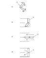
- FIG. 3A shows a damper 13 having two fins as an example of the steam flow adjusting means used in the present invention.
- the two fins of the damper 13 can be opened and closed independently, and the flow rate and wind direction of superheated steam blown to the upper and lower stages of the transfer table can be set in various ways.
- the damper shown in FIG. 3 shows an example in which the damper is used as a steam flow adjusting means between the pressurizing chamber and the drying chamber, but naturally, it can also be used as the steam flow adjusting means 5 between the drying chamber and the decompression chamber. is there.
- the vapor flow adjusting means 5 on the decompression chamber side By appropriately adjusting the vapor flow adjusting means 5 on the decompression chamber side, the flow rate of the vapor flow discharged from the drying chamber can be adjusted, and the dust generated from the dry organic matter can be suppressed from being discharged into the decompression chamber.
- the temperature of superheated steam introduced into the drying chamber is the same from the upper stage to the lower stage.
- the temperature of the lowest stage (the place where drying progressed most) is higher than 250 ° C. and the moisture content of the organic substance treated with superheated steam is 45% or less, the dry distillation that evaporates to the volatile components contained in the organic substance Will occur, and tar will be generated in the steam, resulting in an overdried state.
- the temperature of superheated steam shall be 250 degrees C or less.
- the superheated steam introduction part 7 is formed in the upper part of the pressurizing chamber 2, and the superheated steam lead-out part 8 is formed in the lower part of the decompression chamber 3. Yes.
- the steam discharged from the drying chamber 1 is led out from the relatively low-temperature steam to the outside.
- the temperature of the superheated steam in the decompression chamber is preferably a temperature of 140 ° C. or higher or around 140 ° C.
- the dryer main body and the heat exchanger can be downsized.
- the first stage in the upper stage does not pass superheated steam, the number of effective stages is 12
- the pressure chamber side and the decompression chamber side respectively.
- the temperature control at the blower outlet or the exhaust outlet of the superheated steam becomes easy and stable. Drying becomes possible.
- a multistage organic matter drying system that is easy to control the entire temperature, has high heat utilization efficiency, and can suppress an excessive flow rate of superheated steam even when using a low-temperature heat source. It becomes possible to provide.
Landscapes
- Engineering & Computer Science (AREA)
- Mechanical Engineering (AREA)
- General Engineering & Computer Science (AREA)
- Life Sciences & Earth Sciences (AREA)
- Hydrology & Water Resources (AREA)
- Environmental & Geological Engineering (AREA)
- Water Supply & Treatment (AREA)
- Chemical & Material Sciences (AREA)
- Organic Chemistry (AREA)
- Drying Of Solid Materials (AREA)
- Treatment Of Sludge (AREA)
Abstract
全体の温度コントロールが容易であり、熱利用効率が高く、低温熱源を利用する場合でも過熱蒸気の流速が過多となるのを抑制可能な多段型有機物乾燥システムを提供することを目的とする。 有機物を上段から下段に向けて多段階5に搬送する搬送手段と、該搬送手段を収容する乾燥室1と、該乾燥室内に過熱蒸気aを送風し、該有機物を乾燥する多段型有機物乾燥システムにおいて、過熱蒸気の導入部7と該乾燥室1との間に、過熱蒸気を該乾燥室1に送風するための加圧室2を有し、過熱蒸気の導出部8と該乾燥室1との間に、過熱蒸気を該乾燥室1から排出するための減圧室3とを有し、該加圧室2と該乾燥室1との間、及び該乾燥室1と該減圧室3との間には、過熱蒸気の流量を調節するための蒸気流調節手段(41~46,5)が設置されていることを特徴とする。
Description
本発明は、多段型有機物乾燥システムに関し、特に、汚泥等、水分を多く含む有機物を乾燥するために使用される多段型有機物乾燥システムに関する。
汚泥等、水分を多く含む有機物を乾燥させるため、有機物を上段から下段に向けて多段階に搬送させると共に、過熱蒸気を送風して有機物を乾燥する多段型有機物乾燥システムが提案されている。
特許文献1に示すように、有機物は、各段に配置されて回転する複数のレーキにより順次横方向に搬送され、各段の端部において一つ下の段に落下し、引き続き下段のレーキにより横方向に搬送されるよう構成されている。このように、有機物は上段から下段に向けて多段階に搬送される。そして、有機物の搬送方向と同じ方向に加熱ガスを流し(並流)、有機物を乾燥させるよう構成している。
また、特許文献2には、有機物の搬送手段の最終工程(乾燥末期)において、風量の少ない蒸発蒸気を接触させ、乾燥不足を補うと共に、粉塵が蒸気に混入するのを抑制し、集塵装置が大型化するのを抑制することが開示されている。
有機物の搬送方向と過熱蒸気の流れ方向との関係は、両者が同方向に移動する「並流方式」だけでなく、両者が互いに逆方向に移動する「交流(向流)方式」がある。並流方式は、温度コントロールが安定するという利点があるが、特許文献1のように、末端における加熱不足の問題がある。交流方式は、熱効率が高く有機物を炭化させることも可能であるが、加熱が局所的となり易く、全体の温度コントロールが難しいという欠点がある。
また、並流方式と交流方式の組み合わせとして、搬送経路の中間位置に過熱蒸気を供給し、有機物の搬送方向に対して上流側に交流で過熱蒸気を流し、下流側に並流で過熱蒸気を流す、所謂、「2分流方式」による乾燥方法もある。しかしながら、多段型有機物乾燥システムでは、上段では、高温が必要であり、下段では、低温での乾燥が必要となる。このため、2分流方式では、乾燥機入口の過熱蒸気温度は1つであるため、上流側の条件と下流側の条件とを同時に満足することは難しく、非効率かつ運転制御が困難であるという難点があった。
また、並流方式や交流方式のみで通過流路を形成したり、2分流方式のみで通過流路を形成する場合には、通過流路が長くなり、過熱蒸気の温度応答性が悪く、過乾燥又乾燥不足が発生し易いという問題があった。しかも長い流路は内部圧力損失が増大し、循環ファンが大型化するという問題も生じていた。
さらに、低温熱源(300℃台の排ガス)による乾燥を行う場合、伝熱面積が大きくなり、過熱蒸気循環型の乾燥機の場合、循環蒸気の流量が発生蒸気流量の12~15倍程度となるため、乾燥機内部での流速が過多となり易く、ダストの飛散等の問題が発生する。
本発明が解決しようとする課題は、上述の問題を解消し、全体の温度コントロールが容易であり、熱利用効率が高く、低温熱源を利用する場合でも過熱蒸気の流速が過多となるのを抑制可能な多段型有機物乾燥システムを提供することである。
上記課題を解決するため、本発明の多段型有機物乾燥システムは以下のような技術的特徴を有する。
(1)有機物を上段から下段に向けて多段階に搬送する搬送手段と、該搬送手段を収容する乾燥室と、該乾燥室内に過熱蒸気を送風し、該有機物を乾燥する多段型有機物乾燥システムにおいて、過熱蒸気の導入部と該乾燥室との間に、過熱蒸気を該乾燥室に送風するための加圧室を有し、過熱蒸気の導出部と該乾燥室との間に、過熱蒸気を該乾燥室から排出するための減圧室とを有し、該加圧室と該乾燥室との間、及び該乾燥室と該減圧室との間には、過熱蒸気の流量を調節するための蒸気流調節手段が設置されていることを特徴とする。
(1)有機物を上段から下段に向けて多段階に搬送する搬送手段と、該搬送手段を収容する乾燥室と、該乾燥室内に過熱蒸気を送風し、該有機物を乾燥する多段型有機物乾燥システムにおいて、過熱蒸気の導入部と該乾燥室との間に、過熱蒸気を該乾燥室に送風するための加圧室を有し、過熱蒸気の導出部と該乾燥室との間に、過熱蒸気を該乾燥室から排出するための減圧室とを有し、該加圧室と該乾燥室との間、及び該乾燥室と該減圧室との間には、過熱蒸気の流量を調節するための蒸気流調節手段が設置されていることを特徴とする。
(2)上記(1)に記載の多段型有機物乾燥システムにおいて、該加圧室と該乾燥室との間に設置された該蒸気流調節手段は、過熱蒸気が流れる方向を、該搬送手段の上段側、下段側、又は上段側と下段側との両方、のいずれかに切り替える、風向調節機能を有することを特徴とする。
(3)上記(1)又は(2)に記載の多段型有機物乾燥システムにおいて、該過熱蒸気の導入部は該加圧室の上部に形成され、該過熱蒸気の導出部は該減圧室の下部に形成されていることを特徴とする。
(4)上記(1)乃至(3)のいずれかに記載の多段型有機物乾燥システムにおいて、該加圧室と該乾燥室との間に設置された該蒸気流調節手段は、含水率が45%以下の有機物を搬送している段には、送風される過熱蒸気の温度が250℃以下になるように調節されていることを特徴とする。
(5)上記(1)乃至(4)のいずれかに記載の多段型有機物乾燥システムにおいて、該乾燥室と該減圧室との間に設置された該蒸気流調節手段は、該減圧室の過熱蒸気が所定温度になるように、該蒸気流調節手段が調節されていることを特徴とする。
本発明の多段型有機物乾燥システムでは、過熱蒸気の導入部と該乾燥室との間に、過熱蒸気を該乾燥室に送風するための加圧室を有し、過熱蒸気の導出部と該乾燥室との間に、過熱蒸気を該乾燥室から排出するための減圧室とを有し、しかも、該加圧室と該乾燥室との間、及び該乾燥室と該減圧室との間には、過熱蒸気の流量を調節するための蒸気流調節手段が設置されているため、温度コントロールがし易く、過熱蒸気の熱利用効率も高く設定できる。しかも、過熱蒸気の流速が、過剰に増加することも抑制することが可能となる。
さらに、加圧室と乾燥室との間に設置された蒸気流調節手段は、過熱蒸気が流れる方向を、搬送手段の上段側、下段側、又は上段側と下段側との両方、のいずれかに切り替える、風向調節機能を有するため、各段毎に交流方式と並流方式の使い分けが可能となり、熱利用効率を高くすることができる。過熱蒸気が流れる方向を搬送手段の上段側に切り替えたときには、該加圧室から送風された過熱蒸気が、搬送手段の搬送方向と逆方向に流れる空気流(交流方式)を形成するため、有機物を効果的に乾燥させることができ、過熱蒸気が流れる方向を搬送手段の下段側に切り替えたときには、該加圧室から送風された過熱蒸気が、搬送手段の搬送方向と同方向に流れる空気流(並流)を形成するため、温度コントロールを行い易くすることが可能となる。
そして、過熱蒸気の導入部は加圧室の上部に形成され、過熱蒸気の導出部は減圧室の下部に形成されているため、加圧室では、搬送手段の上段に高温の蒸気を供給し易くなり、減圧室では、乾燥室から排出された蒸気のうち比較的低温の蒸気から外部に導出することが可能となる。さらに、該導入部と該導出部はそれぞれ有機物乾燥システムの対角線上に位置しているため、該有機物乾燥システム全体の空気の循環を円滑にすることができる。
また、加圧室と乾燥室との間に設置された蒸気流調節手段は、含水率が45%以下の有機物を搬送している段には、送風される過熱蒸気の温度が250℃以下になるように調節されているため、有機物の過乾燥を抑止できる。
さらに、乾燥室と減圧室との間に設置された蒸気流調節手段は、該減圧室の過熱蒸気が所定温度になるように調節されているため、過熱蒸気の温度を最適化することで、過熱蒸気を循環利用する際に、過熱蒸気が持つ熱の利用効率も向上させることができる。
本発明を以下の好適例により説明するがこれらに限定されるものではない。
本発明の多段型有機物乾燥システムは、汚泥等の水分を含む有機物を上段から下段に向けて多段階に搬送する搬送手段(各段を符号6で示す)と、該搬送手段を収容する乾燥室1と、該乾燥室1内に過熱蒸気aを送風し、該有機物を乾燥する多段型有機物乾燥システムにおいて、過熱蒸気aの導入部7と該乾燥室1の間に、過熱蒸気aを該該乾燥室1に送風するための加圧室2と、過熱蒸気aの導出部8と該乾室1の間に、過熱蒸気aを該乾燥室1から排出するための減圧室3とを有し、該加圧室2と該乾燥室1との間、及び該乾燥室1と該減圧室3との間には、過熱蒸気aの流量を調節するための蒸気流量調節手段(5、41~46)が設置されていることを特徴とする。
本発明の多段型有機物乾燥システムは、汚泥等の水分を含む有機物を上段から下段に向けて多段階に搬送する搬送手段(各段を符号6で示す)と、該搬送手段を収容する乾燥室1と、該乾燥室1内に過熱蒸気aを送風し、該有機物を乾燥する多段型有機物乾燥システムにおいて、過熱蒸気aの導入部7と該乾燥室1の間に、過熱蒸気aを該該乾燥室1に送風するための加圧室2と、過熱蒸気aの導出部8と該乾室1の間に、過熱蒸気aを該乾燥室1から排出するための減圧室3とを有し、該加圧室2と該乾燥室1との間、及び該乾燥室1と該減圧室3との間には、過熱蒸気aの流量を調節するための蒸気流量調節手段(5、41~46)が設置されていることを特徴とする。
本発明の多段型有機物乾燥システムに使用される搬送手段としては、図2に示すように、各段の搬送テーブル5の上にレーキ11を複数配置し、各レーキ11を各段を貫通して配置される回転軸12により回転させることにより構成されている。図2(a)は、各段に配置されるレーキの平面図であり、図2(b)は横方向から見た側面図である。各レーキが回転することにより、有機物は矢印A及びB方向に順次搬送される。搬送手段としては、図2に示すレーキに限らず、無端ベルトによる搬送手段も利用可能であるが、有機物と過熱蒸気との接触面積を増加させるため、レーキのような撹拌機能も付加した搬送手段を用いることが好ましい。
図1に示すように、有機物は乾燥室内の上段から下段に順次搬送されながら、乾燥室内に送風された過熱蒸気により乾燥され、最終的には、乾燥汚泥等の乾燥した有機物(乾燥有機物)として排出される。乾燥有機物は、燃焼炉で焼却されたり、セメント製造設備等の燃料として焼却されたりする。
本発明の多段型有機物乾燥システムの特徴は、図1に示すように、乾燥室1の過熱蒸気の入口側に加圧室2を設け、乾燥室1の過熱蒸気の出口側に減圧室3を設けることである。そして、乾燥室1と加圧室2との間と、乾燥室1と減圧室3との間に、複数の連通孔を形成し、各連通孔に過熱蒸気の流量を調整する蒸気流調整手段(41~46,5)を設けている。
このような構成を採用することにより、有機物の乾燥状態に応じて、上段から下段に至る各段階の任意の場所から過熱蒸気を必要な流量だけ乾燥室1内に導入することができ、また、過熱蒸気の排出が必要な位置から必要な流量だけ、乾燥室1から過熱蒸気を排出することができる。
しかも、図1に示すように、搬送手段の全段階において、過熱蒸気の流路を1つの搬送段階のみの長さに最短化することもでき、乾燥室内部での流速を最も遅くすることも可能となる。
さらに、後述するように、乾燥室1の入口側に配置された蒸気流調整手段(41~46)には、搬送手段の上段側、下段側、又は上段側と下段側との両方、のいずれかに切り替える、風向調節機能も付加でき、これにより、各段毎に交流方式と並流方式の使い分けが可能となる。
また、乾燥室1の出口側に配置された蒸気流調整手段5を操作して乾燥室から排出される過熱蒸気の温度を調整することもでき、過熱蒸気の持つ熱を効率的に利用することも可能となる。
次に、図1に示す多段型有機物乾燥システムにおける過熱蒸気の流れについて説明する。まず所定の温度に加熱された過熱蒸気aが、加圧室2の入口となる導入部7に導入される。加圧室2は、チャンバーの役割を果たし、蒸気流調整手段(41~46)を選択的に動作させることにより、加圧室内に蓄積された過熱蒸気を安定的に乾燥室1内に供給することができる。
過熱蒸気は、蒸気流調節手段(41~46)によって、その流量と乾燥室1内に送風される際の風向とが調節されながら乾燥室1内に送風され、乾燥室内を搬送される有機物を乾燥させる。また、乾燥室1と減圧室3との間に設置された蒸気流調節手段5を動作させることにより、減圧室3内に排出される過熱蒸気の流量を調整することができる。そして、どの位置の蒸気流調整手段5を操作するかによって、排出される過熱蒸気の温度が異なるため、蒸気流調整手段5の操作により減圧室3内に排出された過熱蒸気の温度を調整することも可能となる。
減圧室3は、乾燥室1内の過熱蒸気を吸い出す、吸引チャンバーの役割を果たす。減圧室3の減圧状態は、送風ファン10によって実現される。減圧室3から導出部8を経て、過熱蒸気(循環蒸気。符号b)が排出され、送風ファン10へと送られる。送風ファン10を通過した蒸気は、熱交換器9に送られ、所定の温度まで上昇させた後に、過熱蒸気aとして再利用されることとなる。
本発明の多段型有機物乾燥システムでは、上述したように、過熱蒸気を循環して使用するのが好ましい。これは、汚泥等の有機物を乾燥した際に発生する臭いを外部に放出することを抑制でき、しかも、過熱蒸気が保持する熱量を有効利用するためである。
有機物を乾燥すると、蒸気が発生し過熱蒸気に混入することとなる。このため、過熱蒸気の圧力が高まるため、不要な蒸気は、余剰蒸気(有機物から蒸発した蒸気)として、外部に排出される。この際、余剰蒸気を焼却炉又はセメント製造設備に供給する空気の一部に使用することで、余剰蒸気を高温で処理することができ、蒸気に含まれる臭いも分解除去される。
熱交換器9には、燃焼炉やセメント製造設備で排出される燃焼ガス等の高温の排出ガスが導入される。本発明の多段型有機物乾燥システムでは、熱交換器に導入される燃焼ガス等の加熱用ガスの温度は、約300℃程度の低温熱源を利用する場合でも、乾燥室内の過熱蒸気の流路が極端に短くできるため、乾燥室内部での過熱蒸気の流速が過多となることが無い。つまり、低温熱源を利用する場合に、過熱蒸気(循環蒸気)量が有機物から蒸発する蒸発蒸気量の12~15倍となるが、各過熱蒸気が通過する流路が短くなることで蒸気通過面積を抑制できるため、過熱蒸気の流速は過多とならない。
本発明の多段型有機物乾燥システムでは、乾燥室に送風される過熱蒸気の流量及び流れる方向を調節する蒸気流調節手段(41~46)と、乾燥室から排出される過熱蒸気の流量を調節する蒸気流調節手段5と適宜組み合わせて動作させることで、多様な流路を形成することができる。
さらに、乾燥室に送風する過熱蒸気の流量を乾燥室から排出する過熱蒸気の流量よりも大きくした場合には、過熱蒸気が乾燥室内に滞留し易くなり、過熱蒸気の圧力を高め、過熱蒸気の熱容量を増加させた乾燥を行うことが可能となる。また、乾燥室から排出する過熱蒸気の流量を乾燥室に送風する過熱蒸気の流量よりも大きくした場合には、過熱蒸気の流れを円滑化することが可能となり、過熱蒸気の循環を効率的に行うことが可能となる。
また、加圧室2と乾燥室1との間に設置された蒸気流調節手段(41~46)は、過熱蒸気が流れる方向を、搬送手段の上段側、下段側、又は上段側と下段側との両方に切り替える、風向調節機能を有しているため、有機物の搬送路の途中で、並流方式や交流方式の部分を適宜設定できる。このため、温度コントロールがし易く、過熱蒸気の熱利用効率も高く設定できる。
過熱蒸気が流れる方向を搬送手段の上段側に切り替えたときには、該加圧室から送風された過熱蒸気が、搬送手段の搬送方向と逆方向に流れる空気流(交流方式)を形成するため、有機物を効果的に乾燥させることができる。また、過熱蒸気が流れる方向を搬送手段の下段側に切り替えたときには、該加圧室から送風された過熱蒸気が、搬送手段の搬送方向と同方向に流れる空気流(並流)を形成するため、温度コントロールを行い易くすることが可能となる。
各蒸気流調節手段としては、図1に示すような1枚のフィンからなるダンパーで構成することも可能であるが、これに限らず図3のようなダンパーを使用することも可能である。図3(a)には、本発明に使用する蒸気流調節手段の一例として、二枚のフィンを備えたダンパー13を示す。ダンパー13の二枚のフィンは、それぞれ独立して開閉可能であり、搬送テーブルの上段側及び下段側に送風される過熱蒸気の流量及び風向を多様に設定することができる。
ダンパー13を用いると、図3(b)のように上段側を閉じ、下段側を開くことで過熱蒸気を下段のみに送風することができる。また、図3(c)のようにダンパー13を搬送テーブルと水平にすることで、上段側と下段側の蒸気を混合させずに、上段側には交流の蒸気流を、下段側には並流の蒸気流を形成することができる。そして、図3(d)のように、ダンパーを完全に閉じた場合には、加圧室からの蒸気流の流入を防ぎ、過乾燥等を防止できる。
図3に示すダンパーは、加圧室と乾燥室の間の蒸気流調節手段として使用する例を示したが、当然、乾燥室と減圧室との間の蒸気流調節手段5としても利用可能である。減圧室側の蒸気流調節手段5を適切に調節することで、乾燥室から排出される蒸気流の流量を調節できると共に、乾燥有機物から発生する粉塵が減圧室に排出するのを抑制できる。
また、乾燥室内に導入される過熱蒸気の温度は、上段から下段まで同じ温度になる。最下段(もっとも乾燥が進んだ場所)の温度が250℃より高い場合、かつ、過熱蒸気で処理される有機物の含水率が45%以下の場合には、有機物に含まれる揮発成分まで蒸発させる乾溜が生じ、蒸気中にタールが発生する等、過乾燥状態となる。このため、過熱蒸気の温度は250℃以下とすることが好ましい。
本発明の多段型有機物乾燥システムでは、図1に示すように、過熱蒸気の導入部7は加圧室2の上部に形成し、過熱蒸気の導出部8は減圧室3の下部に形成している。これは、加圧室2では、搬送手段の上段に高温の蒸気を供給し易くなり、減圧室3では、乾燥室1から排出された蒸気のうち比較的低温の蒸気から外部に導出することを可能とし、さらに、該導入部と該導出部をそれぞれ有機物乾燥システムの対角線上に配置することにより、有機物乾燥システム全体の空気の循環を円滑にするためである。
また、乾燥室1と減圧室3との間に設置された蒸気流調節手段5は、減圧室3の過熱蒸気の温度が所定温度になるように調節されているため、過熱蒸気の熱利用効率を高め、これらを循環蒸気として再利用し、新たな過熱蒸気aとして供給することができる。なお、この減圧室内の過熱蒸気の温度としては、140℃以上又は140℃前後の温度が好ましい。
本発明の多段型有機物乾燥システムでは、工業的に利用価値の低い300℃以下の低温熱源を利用する場合でも、図1に示すように、複数の過熱蒸気の流路が確保され、流路が短く、流量の増加も抑制できるため、乾燥機本体や熱交換機を小型化することが可能となる。
しかも、例えば、図1のように13段の多段型乾燥機(上段の1段目は、過熱蒸気を通さないため、有効段数は12段となる)では、加圧室側及び減圧室側それぞれに最大6か所ずつ蒸気流調節手段を設置することにより、12蒸気流路となり、各段共に交流・並流の使い分けが可能となる。また、1流路方法式に比べると、内部流速が1/12となり、流速の2乗に比例して増大する内部圧力損失を大幅に低減することができる。このため、循環ファンの設置をする必要がなくなり、装置の小型化、省電力化を図ることができる。
そして本発明では、有機物の搬送経路を複数に分けて過熱蒸気と接触させる、所謂、分流処理を行うため、過熱蒸気の乾燥室への送風口又排出口での温度制御が容易になり、安定した乾燥が可能となる。
以上のように、本発明により、全体の温度コントロールが容易であり、熱利用効率が高く、低温熱源を利用する場合でも過熱蒸気の流速が過多となるのを抑制可能な多段型有機物乾燥システムを提供することが可能となる。
1 乾燥室
2 加圧室
3 減圧室
5、13、41~46 蒸気流調節手段
6 搬送テーブル
7 過熱蒸気導入部
8 過熱蒸気導出部
9 熱交換器
10 送風ファン
11 レーキ
12 回転軸
a、b 過熱蒸気の流れ
2 加圧室
3 減圧室
5、13、41~46 蒸気流調節手段
6 搬送テーブル
7 過熱蒸気導入部
8 過熱蒸気導出部
9 熱交換器
10 送風ファン
11 レーキ
12 回転軸
a、b 過熱蒸気の流れ
Claims (5)
- 有機物を上段から下段に向けて多段階に搬送する搬送手段と、該搬送手段を収容する乾燥室と、該乾燥室内に過熱蒸気を送風し、該有機物を乾燥する多段型有機物乾燥システムにおいて、
過熱蒸気の導入部と該乾燥室との間に、過熱蒸気を該乾燥室に送風するための加圧室を有し、
過熱蒸気の導出部と該乾燥室との間に、過熱蒸気を該乾燥室から排出するための減圧室とを有し、
該加圧室と該乾燥室との間、及び該乾燥室と該減圧室との間には、過熱蒸気の流量を調節するための蒸気流調節手段が設置されていることを特徴とする多段型有機物乾燥システム。 - 請求項1に記載の多段型有機物乾燥システムにおいて、該加圧室と該乾燥室との間に設置された該蒸気流調節手段は、過熱蒸気が流れる方向を、該搬送手段の上段側、下段側、又は上段側と下段側との両方、のいずれかに切り替える、風向調節機能を有することを特徴とする多段型有機物乾燥システム。
- 請求項1又は2に記載の多段型有機物乾燥システムにおいて、該過熱蒸気の導入部は該加圧室の上部に形成され、該過熱蒸気の導出部は該減圧室の下部に形成されていることを特徴とする多段型有機物乾燥システム。
- 請求項1乃至3のいずれかに記載の多段型有機物乾燥システムにおいて、該加圧室と該乾燥室との間に設置された該蒸気流調節手段は、含水率が45%以下の有機物を搬送している段には、送風される過熱蒸気の温度が250℃以下になるように調節されていることを特徴とする多段型有機物乾燥システム。
- 請求項1乃至4のいずれかに記載の多段型有機物乾燥システムにおいて、該乾燥室と該減圧室との間に設置された該蒸気流調節手段は、該減圧室の過熱蒸気が所定温度になるように、該蒸気流調節手段が調節されていることを特徴とする多段型有機物乾燥システム。
Priority Applications (1)
| Application Number | Priority Date | Filing Date | Title |
|---|---|---|---|
| CN201180069774.4A CN103459959B (zh) | 2011-03-30 | 2011-05-12 | 多级式有机物干燥系统 |
Applications Claiming Priority (2)
| Application Number | Priority Date | Filing Date | Title |
|---|---|---|---|
| JP2011-074517 | 2011-03-30 | ||
| JP2011074517A JP5423712B2 (ja) | 2011-03-30 | 2011-03-30 | 多段型有機物乾燥システム |
Publications (1)
| Publication Number | Publication Date |
|---|---|
| WO2012132026A1 true WO2012132026A1 (ja) | 2012-10-04 |
Family
ID=45950573
Family Applications (1)
| Application Number | Title | Priority Date | Filing Date |
|---|---|---|---|
| PCT/JP2011/060901 Ceased WO2012132026A1 (ja) | 2011-03-30 | 2011-05-12 | 多段型有機物乾燥システム |
Country Status (4)
| Country | Link |
|---|---|
| JP (1) | JP5423712B2 (ja) |
| CN (2) | CN103459959B (ja) |
| TW (1) | TWI554737B (ja) |
| WO (1) | WO2012132026A1 (ja) |
Families Citing this family (8)
| Publication number | Priority date | Publication date | Assignee | Title |
|---|---|---|---|---|
| JP5423712B2 (ja) * | 2011-03-30 | 2014-02-19 | 住友大阪セメント株式会社 | 多段型有機物乾燥システム |
| CN105157396B (zh) * | 2013-01-04 | 2017-09-29 | 浙江红绿蓝纺织印染有限公司 | 用于三废综合回收处理的连续干燥系统及其工作方法 |
| KR101497568B1 (ko) * | 2014-06-17 | 2015-03-02 | 주식회사 한국테크놀로지 | 석탄 건조 장치에서의 재열증기 공급 챔버의 증기압 조절 장치 |
| KR101524567B1 (ko) * | 2015-01-02 | 2015-06-01 | 주식회사 한국테크놀로지 | 석탄 건조 장치에서의 낙하 석탄의 이송에 따른 분진 차폐 장치 |
| CN105486073B (zh) * | 2016-01-25 | 2017-06-16 | 吉林大学 | 一种湿热控速薄层横流干燥试验台 |
| CN109489410A (zh) * | 2018-12-19 | 2019-03-19 | 宝莲华新能源技术(上海)股份有限公司 | 一种适用于烘干房的气体流量自动分配装置 |
| CN114294942B (zh) * | 2021-12-23 | 2022-12-20 | 珠海格力电器股份有限公司 | 热泵烘干系统及其控制方法 |
| CN118310283A (zh) * | 2024-04-22 | 2024-07-09 | 义乌市易开盖实业公司 | 一种带沿程温度调节的中心进风式的干燥系统 |
Citations (2)
| Publication number | Priority date | Publication date | Assignee | Title |
|---|---|---|---|---|
| JP2004174426A (ja) * | 2002-11-28 | 2004-06-24 | Asia Plant Service Kk | 廃棄物処理装置 |
| JP2004190990A (ja) * | 2002-12-13 | 2004-07-08 | Azu Kiyaria Kk | ガス接触式乾燥方法及びその装置 |
Family Cites Families (6)
| Publication number | Priority date | Publication date | Assignee | Title |
|---|---|---|---|---|
| DE642322C (de) * | 1934-02-17 | 1937-03-03 | Chemische Fabriken | Stufentrockner fuer rieselfaehige Stoffe |
| CN1044333A (zh) * | 1989-01-17 | 1990-08-01 | 佐藤次郎 | 木材干燥的方法及其装置 |
| JPH07144987A (ja) * | 1993-11-17 | 1995-06-06 | Yuukishitsu Hiryo Seibutsu Kassei Riyou Gijutsu Kenkyu Kumiai | 汚泥の堆肥化方法及び装置 |
| JP2004010773A (ja) * | 2002-06-07 | 2004-01-15 | Tokyo Yogyo Co Ltd | 内燃式多段炭化炉 |
| CN201488512U (zh) * | 2009-07-23 | 2010-05-26 | 杭州景生木业机械有限公司 | 干燥房专用风门 |
| JP5423712B2 (ja) * | 2011-03-30 | 2014-02-19 | 住友大阪セメント株式会社 | 多段型有機物乾燥システム |
-
2011
- 2011-03-30 JP JP2011074517A patent/JP5423712B2/ja not_active Expired - Fee Related
- 2011-05-12 CN CN201180069774.4A patent/CN103459959B/zh active Active
- 2011-05-12 CN CN2011201533448U patent/CN202195668U/zh not_active Expired - Fee Related
- 2011-05-12 TW TW100116666A patent/TWI554737B/zh not_active IP Right Cessation
- 2011-05-12 WO PCT/JP2011/060901 patent/WO2012132026A1/ja not_active Ceased
Patent Citations (2)
| Publication number | Priority date | Publication date | Assignee | Title |
|---|---|---|---|---|
| JP2004174426A (ja) * | 2002-11-28 | 2004-06-24 | Asia Plant Service Kk | 廃棄物処理装置 |
| JP2004190990A (ja) * | 2002-12-13 | 2004-07-08 | Azu Kiyaria Kk | ガス接触式乾燥方法及びその装置 |
Also Published As
| Publication number | Publication date |
|---|---|
| TW201239301A (en) | 2012-10-01 |
| JP2012207871A (ja) | 2012-10-25 |
| CN103459959A (zh) | 2013-12-18 |
| TWI554737B (zh) | 2016-10-21 |
| CN103459959B (zh) | 2015-08-26 |
| CN202195668U (zh) | 2012-04-18 |
| JP5423712B2 (ja) | 2014-02-19 |
Similar Documents
| Publication | Publication Date | Title |
|---|---|---|
| JP5423712B2 (ja) | 多段型有機物乾燥システム | |
| CN101379167B (zh) | 处理生物质的方法和装置 | |
| JP7852034B2 (ja) | 缶乾燥水分制御システム | |
| CN103249818A (zh) | 生物质烘干系统与方法 | |
| US10450523B2 (en) | Method and apparatus for torrefaction of biomass with a cyclonic bed reactor | |
| JP5631644B2 (ja) | 乾燥排ガスの熱を利用するヒートポンプユニットを具えた乾燥システム | |
| CN110410796A (zh) | 工业废弃物处理系统及方法 | |
| JP5423711B2 (ja) | 多段型有機物乾燥システム | |
| JP5878468B2 (ja) | ヒートポンプユニットを具えた乾燥排ガス循環式乾燥システム | |
| JP2021529933A (ja) | 湿式マトリックス用の乾燥装置及び湿式マトリックスの相対的な乾燥方法 | |
| JP5615020B2 (ja) | 連続式箱型乾燥機が具えられた乾燥設備 | |
| KR101843316B1 (ko) | 슬러지 복합건조장치 | |
| JP2004044874A (ja) | 乾燥装置 | |
| CN212618367U (zh) | 节能型双转轮高浓度冷侧旁通过温控制系统 | |
| CN105066631B (zh) | 一种双向通入热风的高效烘茧机 | |
| CN113970109A (zh) | 节能型双转轮高浓度冷侧旁通过温控制系统及其方法 | |
| JP5704562B2 (ja) | 脱水ケーキの搬送方法 | |
| JP2022178788A (ja) | 固液分離装置、燃料用原料の製造方法および食品材料の製造方法 | |
| RU165396U1 (ru) | Сушильная установка | |
| JP2020159576A (ja) | 間接加熱式乾燥設備 | |
| WO2026037871A1 (en) | A system for steam drying extruded fish feed | |
| TWM609440U (zh) | 節能型單轉輪高濃度熱旁通過溫控制系統 | |
| WO2019097637A1 (ja) | 有機溶剤含有ガス処理システム |
Legal Events
| Date | Code | Title | Description |
|---|---|---|---|
| 121 | Ep: the epo has been informed by wipo that ep was designated in this application |
Ref document number: 11862173 Country of ref document: EP Kind code of ref document: A1 |
|
| NENP | Non-entry into the national phase |
Ref country code: DE |
|
| 122 | Ep: pct application non-entry in european phase |
Ref document number: 11862173 Country of ref document: EP Kind code of ref document: A1 |