WO2012132002A1 - カム軸の位相可変装置 - Google Patents
カム軸の位相可変装置 Download PDFInfo
- Publication number
- WO2012132002A1 WO2012132002A1 PCT/JP2011/058311 JP2011058311W WO2012132002A1 WO 2012132002 A1 WO2012132002 A1 WO 2012132002A1 JP 2011058311 W JP2011058311 W JP 2011058311W WO 2012132002 A1 WO2012132002 A1 WO 2012132002A1
- Authority
- WO
- WIPO (PCT)
- Prior art keywords
- hydraulic pressure
- phase
- hydraulic
- camshaft
- varying device
- Prior art date
Links
Images


Classifications
-
- F—MECHANICAL ENGINEERING; LIGHTING; HEATING; WEAPONS; BLASTING
- F01—MACHINES OR ENGINES IN GENERAL; ENGINE PLANTS IN GENERAL; STEAM ENGINES
- F01L—CYCLICALLY OPERATING VALVES FOR MACHINES OR ENGINES
- F01L1/00—Valve-gear or valve arrangements, e.g. lift-valve gear
- F01L1/34—Valve-gear or valve arrangements, e.g. lift-valve gear characterised by the provision of means for changing the timing of the valves without changing the duration of opening and without affecting the magnitude of the valve lift
- F01L1/344—Valve-gear or valve arrangements, e.g. lift-valve gear characterised by the provision of means for changing the timing of the valves without changing the duration of opening and without affecting the magnitude of the valve lift changing the angular relationship between crankshaft and camshaft, e.g. using helicoidal gear
- F01L1/3442—Valve-gear or valve arrangements, e.g. lift-valve gear characterised by the provision of means for changing the timing of the valves without changing the duration of opening and without affecting the magnitude of the valve lift changing the angular relationship between crankshaft and camshaft, e.g. using helicoidal gear using hydraulic chambers with variable volume to transmit the rotating force
-
- F—MECHANICAL ENGINEERING; LIGHTING; HEATING; WEAPONS; BLASTING
- F01—MACHINES OR ENGINES IN GENERAL; ENGINE PLANTS IN GENERAL; STEAM ENGINES
- F01L—CYCLICALLY OPERATING VALVES FOR MACHINES OR ENGINES
- F01L1/00—Valve-gear or valve arrangements, e.g. lift-valve gear
- F01L1/34—Valve-gear or valve arrangements, e.g. lift-valve gear characterised by the provision of means for changing the timing of the valves without changing the duration of opening and without affecting the magnitude of the valve lift
- F01L1/344—Valve-gear or valve arrangements, e.g. lift-valve gear characterised by the provision of means for changing the timing of the valves without changing the duration of opening and without affecting the magnitude of the valve lift changing the angular relationship between crankshaft and camshaft, e.g. using helicoidal gear
-
- F—MECHANICAL ENGINEERING; LIGHTING; HEATING; WEAPONS; BLASTING
- F02—COMBUSTION ENGINES; HOT-GAS OR COMBUSTION-PRODUCT ENGINE PLANTS
- F02D—CONTROLLING COMBUSTION ENGINES
- F02D13/00—Controlling the engine output power by varying inlet or exhaust valve operating characteristics, e.g. timing
- F02D13/02—Controlling the engine output power by varying inlet or exhaust valve operating characteristics, e.g. timing during engine operation
-
- F—MECHANICAL ENGINEERING; LIGHTING; HEATING; WEAPONS; BLASTING
- F01—MACHINES OR ENGINES IN GENERAL; ENGINE PLANTS IN GENERAL; STEAM ENGINES
- F01L—CYCLICALLY OPERATING VALVES FOR MACHINES OR ENGINES
- F01L1/00—Valve-gear or valve arrangements, e.g. lift-valve gear
- F01L1/02—Valve drive
- F01L1/04—Valve drive by means of cams, camshafts, cam discs, eccentrics or the like
- F01L1/047—Camshafts
- F01L1/053—Camshafts overhead type
- F01L2001/0537—Double overhead camshafts [DOHC]
-
- F—MECHANICAL ENGINEERING; LIGHTING; HEATING; WEAPONS; BLASTING
- F01—MACHINES OR ENGINES IN GENERAL; ENGINE PLANTS IN GENERAL; STEAM ENGINES
- F01L—CYCLICALLY OPERATING VALVES FOR MACHINES OR ENGINES
- F01L1/00—Valve-gear or valve arrangements, e.g. lift-valve gear
- F01L1/34—Valve-gear or valve arrangements, e.g. lift-valve gear characterised by the provision of means for changing the timing of the valves without changing the duration of opening and without affecting the magnitude of the valve lift
- F01L1/344—Valve-gear or valve arrangements, e.g. lift-valve gear characterised by the provision of means for changing the timing of the valves without changing the duration of opening and without affecting the magnitude of the valve lift changing the angular relationship between crankshaft and camshaft, e.g. using helicoidal gear
- F01L1/3442—Valve-gear or valve arrangements, e.g. lift-valve gear characterised by the provision of means for changing the timing of the valves without changing the duration of opening and without affecting the magnitude of the valve lift changing the angular relationship between crankshaft and camshaft, e.g. using helicoidal gear using hydraulic chambers with variable volume to transmit the rotating force
- F01L2001/3445—Details relating to the hydraulic means for changing the angular relationship
- F01L2001/34453—Locking means between driving and driven members
- F01L2001/34459—Locking in multiple positions
-
- F—MECHANICAL ENGINEERING; LIGHTING; HEATING; WEAPONS; BLASTING
- F01—MACHINES OR ENGINES IN GENERAL; ENGINE PLANTS IN GENERAL; STEAM ENGINES
- F01L—CYCLICALLY OPERATING VALVES FOR MACHINES OR ENGINES
- F01L1/00—Valve-gear or valve arrangements, e.g. lift-valve gear
- F01L1/34—Valve-gear or valve arrangements, e.g. lift-valve gear characterised by the provision of means for changing the timing of the valves without changing the duration of opening and without affecting the magnitude of the valve lift
- F01L1/344—Valve-gear or valve arrangements, e.g. lift-valve gear characterised by the provision of means for changing the timing of the valves without changing the duration of opening and without affecting the magnitude of the valve lift changing the angular relationship between crankshaft and camshaft, e.g. using helicoidal gear
- F01L1/3442—Valve-gear or valve arrangements, e.g. lift-valve gear characterised by the provision of means for changing the timing of the valves without changing the duration of opening and without affecting the magnitude of the valve lift changing the angular relationship between crankshaft and camshaft, e.g. using helicoidal gear using hydraulic chambers with variable volume to transmit the rotating force
- F01L2001/3445—Details relating to the hydraulic means for changing the angular relationship
- F01L2001/34453—Locking means between driving and driven members
- F01L2001/34466—Locking means between driving and driven members with multiple locking devices
-
- F—MECHANICAL ENGINEERING; LIGHTING; HEATING; WEAPONS; BLASTING
- F01—MACHINES OR ENGINES IN GENERAL; ENGINE PLANTS IN GENERAL; STEAM ENGINES
- F01L—CYCLICALLY OPERATING VALVES FOR MACHINES OR ENGINES
- F01L1/00—Valve-gear or valve arrangements, e.g. lift-valve gear
- F01L1/34—Valve-gear or valve arrangements, e.g. lift-valve gear characterised by the provision of means for changing the timing of the valves without changing the duration of opening and without affecting the magnitude of the valve lift
- F01L1/344—Valve-gear or valve arrangements, e.g. lift-valve gear characterised by the provision of means for changing the timing of the valves without changing the duration of opening and without affecting the magnitude of the valve lift changing the angular relationship between crankshaft and camshaft, e.g. using helicoidal gear
- F01L2001/34486—Location and number of the means for changing the angular relationship
- F01L2001/34493—Dual independent phasing system [DIPS]
Definitions
- the present invention relates to a cam shaft phase varying device, and more particularly to a cam shaft phase varying device provided for a dual-structure cam shaft composed of an inner shaft and an outer shaft.
- Patent Document 1 discloses a valve operating apparatus including a cam shaft including an outer cam shaft and an inner cam shaft, and a first phase control mechanism and a second phase control mechanism provided at both end portions of the cam shaft.
- Patent Document 2 discloses a camshaft composed of an inner shaft and an outer shaft provided with a hydraulic actuator at one end.
- ⁇ Double-structured camshaft rotates according to the input driving force.
- the phase difference between the inner shaft and the outer shaft can be changed in addition to advancing or retarding the phase of the cam shaft as a whole.
- each of the two phase control mechanisms since each of the two phase control mechanisms has the hydraulic chambers for advance and retard, there is a risk that it is disadvantageous for downsizing because of the four hydraulic chambers.
- the two phase control mechanisms are individually provided in the axial direction, there is a risk that the total length in the axial direction is likely to increase, which may be disadvantageous for downsizing.
- the cost may be disadvantageous due to the configuration in which the two phase control mechanisms are individually provided.
- phase control of the camshaft may be complicated.
- torque reaction force is individually applied to each phase control mechanism from the inner shaft and the outer shaft. For this reason, the torque reaction force is canceled or increased depending on the phase difference between the inner shaft and the outer shaft, so that the torque fluctuation of the entire cam shaft is affected. For this reason, it may be difficult to perform phase control of the camshaft as desired.
- the present invention can perform phase control of a dual-structure cam shaft with a configuration that is advantageous for downsizing and is advantageous in terms of cost, and at the same time, can suitably perform phase control of the cam shaft.
- An object of the present invention is to provide a camshaft phase varying device.
- the present invention rotates in response to an input driving force and is provided for a dual-structure cam shaft composed of an inner shaft and an outer shaft, and advances the phase of the cam shaft as a whole by hydraulic pressure.
- a dual-structure cam shaft composed of an inner shaft and an outer shaft
- a camshaft phase varying device including a phase varying section having a hydraulic chamber in a single housing.
- the advance hydraulic pressure chamber, the retard hydraulic pressure chamber, and the phase difference hydraulic chamber are arranged along the circumferential direction of the cam shaft, and constitute a pair of hydraulic chambers that interact with each other. It can be set as the structure which has.
- the phase variable section includes a housing to which a driving force for driving the cam shaft is input as the housing, a first rotor for driving the inner shaft, and a second for driving the outer shaft.
- a rotor, and the first and second rotors sandwiching the housing.
- the first and second rotors may have a sliding portion with the housing on the outer peripheral portion of each rotor main body provided in the first and second rotors.
- the present invention may be configured to include a driving force input portion to which the driving force is input at a position where the housing overlaps the second rotor in the axial direction.
- the inner shaft includes a flange portion provided so as to be sandwiched between the second rotor and the outer shaft in the axial direction in a state where the phase variable portion is provided on the cam shaft. it can.
- the present invention includes, among the inner shaft and the outer shaft, a hydraulic pressure passage portion individually communicating with the advance hydraulic pressure chamber, the retard hydraulic pressure chamber, and the phase difference hydraulic chamber inside the outer shaft. It can be configured.
- the present invention may be configured such that the phase variable portion further includes a restraining portion that restrains the relative operation between the first and second rotors to be releasable.
- the present invention relates to a first hydraulic pressure control valve that is connected to the advance hydraulic pressure chamber and the retard hydraulic pressure chamber and controls a supplied hydraulic pressure, the first hydraulic pressure control valve, and the phase difference liquid.
- a second fluid pressure control valve connected to the pressure chamber and controlling the fluid pressure to be supplied can be further provided.
- the present invention includes a first three-way valve that is connected to the advance hydraulic pressure chamber and the retard hydraulic pressure chamber and switches a supply destination of hydraulic pressure, and the retard hydraulic pressure chamber and the phase difference hydraulic chamber.
- a second three-way valve that is connected and switches a supply destination of the hydraulic pressure; and a hydraulic pressure control valve that is connected to the first and second three-way valves and controls the supplied hydraulic pressure. Can do.
- FIG. 1 is an overall configuration diagram of Example 1.
- FIG. It is a figure which shows the cam shaft mounted in the engine.
- FIG. 3 is an exploded configuration diagram of a phase variable unit according to the first embodiment.
- FIG. 3 is a first cross-sectional view of the phase variable unit according to the first embodiment.
- FIG. 6 is a second cross-sectional view of the phase variable unit according to the first embodiment. It is a figure which shows the hydraulic circuit structure of Example 1.
- FIG. FIG. 3 is a diagram illustrating an example of phase control according to the first embodiment.
- FIG. 6 is an overall configuration diagram of Embodiment 2.
- 6 is a first cross-sectional view of a phase variable unit according to Embodiment 2.
- FIG. FIG. 10 is a second cross-sectional view of the phase variable unit according to the second embodiment.
- FIG. 6 is an overall configuration diagram of Example 3.
- FIG. 6 is a diagram illustrating a hydraulic circuit configuration according to a third embodiment.
- FIG. 6 is a configuration diagram of a phase varying device according to a fourth embodiment. It is a figure which shows the hydraulic circuit structure of Example 4.
- FIG. 10 is a diagram illustrating an example of phase control according to a fourth embodiment.
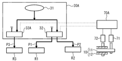
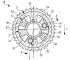
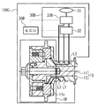
- FIG. 1 is an overall configuration diagram of a cam shaft phase varying device (hereinafter referred to as a phase varying device) 100A of the present embodiment.
- FIG. 2 is a view showing the camshaft 10 mounted on the engine 50.
- FIG. 2 shows a state where the camshaft 10 is provided for the same kind of engine valves (here, intake valves) 51 and 52 that the engine 50 has two per cylinder.
- the engine valve of the same type may be an exhaust valve, for example.
- the phase varying device 100A is configured to include a phase varying unit 1A, a hydraulic pressure (equivalent to hydraulic pressure) circuit unit 30A, and an ECU 70A as an overall configuration.
- the phase variable unit 1A, the hydraulic circuit unit 30A, and the ECU 70A will be sequentially described.
- the phase varying device 100 ⁇ / b> A is provided for the cam shaft 10.
- the phase varying device 100A has a configuration in which the cam shaft 10 further includes a flange portion 11c and hydraulic passage portions L1, L2, and L3, which will be described later, as an overall configuration.
- the cam shaft 10 has a double structure and includes an inner shaft 11 and an outer shaft 12.
- the inner shaft 11 is solid and the outer shaft 12 is hollow.
- the inner shaft 11 is inserted into the outer shaft 12 from one end side.
- the inner shaft 11 and the outer shaft 12 are provided so as to be relatively rotatable with each other in a concentric manner.
- the cam shaft 10 rotates according to the input driving force.
- the camshaft 10 is provided so that the phases of the engine valves 51 and 52 can be changed to different phases on the inner shaft 11 and the outer shaft 12, respectively.
- the cam shaft 10 is provided with a first cam C1 for driving the first engine valve 51 on the inner shaft 11 and a second cam C2 for driving the second engine valve 52 on the outer shaft 12, respectively. ing.
- FIG. 3 is an exploded configuration diagram of the phase variable unit 1A.
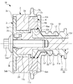
- FIG. 4 is a first cross-sectional view of the phase variable portion 1A.
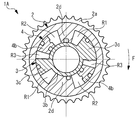
- FIG. 5 is a second cross-sectional view of the phase variable portion 1A. 3 and 4 show the phase variable portion 1A together with the camshaft 10.
- FIG. 4 shows the phase variable portion 1A in a cross section including the central axis.
- FIG. 5 shows the phase variable portion 1A in a cross section orthogonal to the central axis.
- the phase variable unit 1A includes a housing 2, a first rotor 3, and a second rotor 4.
- the housing 2 is a member having a cylindrical basic shape, and has an internal space in which an advance hydraulic chamber R1, a retard hydraulic chamber R2, and a phase difference hydraulic chamber R3 described later are formed.
- the housing 2 includes a driving force input part 2a, a first sliding part 2b, a second sliding part 2c, and a housing vane part 2d.
- the driving force input part 2 a is provided on the outer peripheral part of the housing 2.
- a driving force for driving the camshaft 10 is input to the housing 2 via the driving force input portion 2a.
- the driving force input unit 2a is a chain sprocket.
- a part of the output of the engine 50 can be taken out as a driving force to the driving force input unit 2a and input via a chain.
- the housing 2 is provided with a driving force input portion 2a at a position overlapping the second rotor 4 in the axial direction.
- 1st sliding part 2b is provided inside one end of housing 2.
- the second sliding portion 2 c is provided inside the other end portion of the housing 2.
- the housing vane portion 2d is provided inside the intermediate portion of the housing 2 between the sliding portions 2b and 2c.
- a portion other than the portion where the housing vane portion 2d is provided has a cylindrical inner surface partially divided by the housing vane portion 2d. The inner diameter of this portion is the inner diameter of the housing 2.
- the sliding portions 2b and 2c are concentrically provided around the inside of the housing 2 with an inner diameter larger than the inner diameter of the housing 2.
- the first sliding portion 2b is provided from one end of the housing 2 and the second sliding portion 2c is provided from the other end of the housing 2 at a predetermined depth along the axial direction.
- the housing vane portion 2d is provided so that the cross sections orthogonal to the axial direction have fan-like shapes that are gradually narrower toward the inside in the radial direction.
- the housing vane portion 2d has an inner peripheral surface provided concentrically with the cylindrical inner surface of the intermediate portion of the housing 2 on the radially inner side.
- the axial width of the housing vane portion 2d is determined by the depth of the sliding portions 2b and 2c. A plurality (two in this case) of housing vane portions 2d are provided.
- the first rotor 3 includes a rotor body 3a, a cylindrical portion 3b, and a first vane portion 3c.
- the rotor body 3a has a disk shape.
- a center bolt insertion hole 3aa is provided concentrically along the axial direction in the center of the rotor body 3a.
- the 1st rotor 3 has the sliding part 3ab with the housing 2 in the outer peripheral part of the rotor main body 3a.
- the outer diameter of the rotor body 3a is set equal to the inner diameter of the first sliding portion 2b.
- the axial width of the rotor body 3a is set to be equal to the depth of the first sliding portion 2b.
- the cylindrical portion 3b is provided so as to extend along the axial direction from an end surface on the side assembled toward the housing 2 among both end surfaces of the rotor body 3a.
- the cylindrical portion 3b is provided concentrically with the rotor body 3a.
- the outer diameter of the cylindrical portion 3b is set to be equal to the inner diameter of the inner peripheral surface of the housing vane portion 2d.
- the axial width of the cylindrical portion 3b is set to be equal to the axial width of the housing vane portion 2d.
- the first vane portion 3c is provided over the rotor body 3a and the cylindrical portion 3b.
- the first vane portion 3c extends along the axial direction from the end surface of the rotor body 3a on the side assembled toward the housing 2 among the both end surfaces. Further, the cross sections orthogonal to the axial direction are provided so as to have the same fan-shaped shape gradually widening from the cylindrical portion 3b toward the radially outer side.
- the first vane portion 3c has an outer circumferential surface provided concentrically with the rotor body 3a on the radially outer side.
- the outer diameter of the outer peripheral surface is set to be equal to the inner diameter of the cylindrical inner surface of the middle portion of the housing 2.
- the axial width of the first vane portion 3c is equal to the axial width of the cylindrical portion 3b.
- a plurality of (here, two) first vane portions 3c are provided.
- the second rotor 4 includes a rotor body 4a and a second vane portion 4b.
- the rotor body 4a has a disk shape.
- a cam shaft insertion hole 4aa is provided concentrically along the axial direction in the center of the rotor body 4a.
- the cam shaft insertion hole 4aa has a reduced diameter on the side opposite to the side where the cam shaft 10 is inserted in the axial direction.
- the inner diameter of the reduced portion is set to be larger than the inner diameter of the cylindrical portion 3b and smaller than the outer diameter of the cylindrical portion 3b.
- the end face on the side where the cam shaft insertion hole 4aa is reduced is the end face on the side assembled toward the housing 2.
- the second rotor 4 has a sliding part 4ab with the housing 2 on the outer peripheral part of the rotor body 4a.
- the outer diameter of the rotor body 4a is set to be equal to the inner diameter of the second sliding portion 2c.
- the axial width of the rotor body 4a can be set to be equal to the depth of the second sliding portion 2c or larger than the depth of the sliding portion 2c.
- the second vane portion 4b is provided so as to extend along the axial direction from the end surface on the side assembled toward the housing 2 among the both end surfaces of the rotor body 4a. Further, the cross sections orthogonal to the axial direction are provided so as to have the same fan-shaped shape gradually widening from the inner side to the outer side in the radial direction.
- the second vane portion 4b has an inner peripheral surface provided concentrically with the rotor body 4a on the radially inner side and an outer peripheral surface provided concentrically with the rotor body 4a on the radially outer side.
- the inner diameter of the inner peripheral surface of the second vane portion 4b is set to be equal to the outer diameter of the cylindrical portion 3b.
- the outer diameter of the outer peripheral surface of the second vane portion 4b is set to be equal to the inner diameter of the cylindrical inner surface of the middle portion of the housing 2.
- the axial width of the second vane portion 4b is set to be equal to the axial width of the housing vane portion 2d. A plurality (two in this case) of second vane portions 4b are provided.
- the phase variable unit 1A includes an advance hydraulic chamber R1 that advances the phase of the camshaft 10 as a whole by hydraulic pressure, a retard hydraulic chamber R2 that delays the phase of the camshaft 10 as a whole by hydraulic pressure, and an internal hydraulic pressure.
- the single housing 2 has a phase difference hydraulic chamber R3 for changing a phase difference between the shaft 11 and the outer shaft 12.
- the phase variable portion 1A is configured such that the housing 2 is sandwiched between the rotors 3 and 4.
- the first rotor 3 is specifically provided in the housing 2 so that the rotor main body 3a is accommodated in the first sliding portion 2b and the first vane portion 3c is accommodated in the intermediate portion.
- the second rotor 4 is provided in the housing 2 so that the rotor main body 4a is accommodated in the second sliding portion 2c and the second vane portion 4b is accommodated in the intermediate portion. And thereby, the vane parts 2d, 3c, and 4b are arrange
- the vane portions 2d, 3c, and 4b arranged along the circumferential direction constitute a set of vane portions 2d, 3c, and 4b.
- the phase variable unit 1A includes a plurality of sets (two sets here) of a set of vane units 2d, 3c, and 4b. More specifically, the pair of vane portions 2d, 3c, and 4d are arranged in the order of the housing vane portion 2d, the first vane portion 3c, and the second vane portion 4b in the phase advance direction F. .
- the advance hydraulic chamber R1 is formed between the housing vane portion 2d and the first vane portion 3c adjacent in the circumferential direction.
- the retard hydraulic chamber R2 is formed between the housing vane portion 2d and the second vane portion 4b adjacent in the circumferential direction.
- the phase hydraulic chamber R3 is formed between the vane portions 3c and 4b adjacent in the circumferential direction.
- the hydraulic chambers R1, R2, and R3 are formed so as to interact with each other. In this respect, the hydraulic chambers R1 and R3 interact with each other via the first vane portion 3c, and the hydraulic chambers R2 and R3 interact with each other via the second vane portion 4b.
- the hydraulic chambers R1 and R2 interact with each other via the vanes 3c and 4b.
- the hydraulic chambers R1, R2, and R3 formed in this way constitute a pair of hydraulic chambers R1, R2, and R3 that are arranged along the circumferential direction and interact with each other.
- the phase variable unit 1A has a plurality of sets (two sets here) of a set of hydraulic chambers R1, R2, and R3. More specifically, the hydraulic chambers R1 to R3 are arranged in the order of the advanced hydraulic chamber R1, the phase difference hydraulic chamber R3, and the retarded hydraulic chamber R2 in the phase advance direction F.
- the inner shaft 11 includes a shaft portion 11a, a head portion 11b, and a flange portion 11c.
- the shaft portion 11 a forms a shaft body of the inner shaft 11 and is inserted into the outer shaft 12.
- the head 11b is provided at one end of the shaft portion 11a.
- the head portion 11b has a columnar shape, and is inserted into the cylindrical portion 3b through the cam shaft insertion hole 4aa.
- the outer diameter of the head 11b is set to be equal to the inner diameter of the cylindrical portion 3b.
- the axial width of the head portion 11b is set larger than the axial width of the cylindrical portion 3b.
- the collar part 11c is provided over the circumference of the end part on the shaft part 11a side of the head part 11b.
- the outer diameter of the flange portion 11c is set to be larger than the diameter of the portion of the cam shaft insertion hole 4aa that is reduced in diameter and smaller than the diameter of the portion that is not reduced.
- the inner shaft 11 is concentrically provided with a center bolt hole that opens in the center of the head 11b.
- the outer shaft 12 includes a shaft portion 12a, a tip portion 12b, a flange portion 12c, and a hollow portion 12d.
- the shaft portion 12 a forms the shaft body of the outer shaft 12.
- the distal end portion 12 b is provided at one end portion of the outer shaft 12.
- the distal end portion 12b has a cylindrical shape and is inserted into the cam shaft insertion hole 4aa.
- the outer diameter of the tip 12b is set to be equal to the inner diameter of the portion of the camshaft insertion hole 4aa that is not reduced.
- the axial width of the distal end portion 12b is set smaller than the width of the portion of the cam shaft insertion hole 4aa that is not reduced in diameter.
- the flange portion 12c is provided over the circumference at the end portion on the shaft portion 12a side of the tip end portion 12b.
- Bolt insertion holes are provided in the flange portion 12c along the axial direction.
- a plurality of bolt insertion holes are equally provided along the circumferential direction.
- the hollow portion 12d is provided concentrically along the axial direction.
- the hollow portion 12d has a cylindrical inner surface and opens at the center of the tip portion 12b.
- the inner diameter of the hollow portion 12d is set to be equal to the outer diameter of the shaft portion 11a.
- the phase variable portion 1A integrates the first rotor 3 and the inner shaft 11 and the second rotor 4 and the outer shaft 12 in a state where the housing 2 is sandwiched between the rotors 3 and 4. Is provided on the camshaft 10.
- the first rotor 3 is integrated with the inner shaft 11 by being fixed to the inner shaft 11 with a center bolt 21.
- the second rotor 4 is integrated with the outer shaft 12 by being fixed to the outer shaft 12 with a plurality of fastening bolts 22.
- the center bolt 21 is tightened into the center bolt hole through the center bolt insertion hole 3aa.
- the fastening bolt 22 is fastened into a bolt hole provided in the rotor body 4a through a bolt insertion hole.
- the first rotor 3 and the inner shaft 11 are provided with a first knock pin 23 that is a first positioning member.
- the first knock pin 23 is provided over the rotor main body 3a and the head 11b.
- the first knock pin 23 performs circumferential positioning between the first rotor 3 and the inner shaft 11.
- the second rotor 4 and the outer shaft 12 are provided with a second knock pin 24 that is a second positioning member.
- the second knock pin 24 is provided over the rotor body 4a and the flange portion 12c.
- the second knock pin 24 performs positioning in the circumferential direction between the second rotor 4 and the outer shaft 12.
- the phase varying device 100 ⁇ / b> A has a configuration in which the inner shaft 11 includes a flange portion 11 c provided so as to be sandwiched between the second rotor 4 and the outer shaft 12 with the phase varying portion 1 ⁇ / b> A provided on the cam shaft 10.
- the flange portion 11c specifically includes a portion and a tip of the second rotor 4 in which the diameter of the cam shaft insertion hole 4aa is reduced in the axial direction with the phase variable portion 1A provided on the cam shaft 10. It is provided so that it may be located between the parts 12b.
- the axial width of the flange portion 11c is such that the second rotor 4 and the outer shaft 12 are integrated, and the portion of the second rotor 4 where the cam shaft insertion hole 4aa is reduced in diameter and the distal end portion. 12b is set to be equal to the width of the gap formed between them.
- the phase varying device 100A further includes, among the inner shaft 11 and the outer shaft 12, hydraulic passage portions L1, L2, and L3 that communicate with the hydraulic chambers R1, R2, and R3 individually inside the outer shaft 12.
- the hydraulic passage portions L 1, L 2, L 3 are provided over the outer shaft 12 and the second rotor 4.
- Each of the hydraulic passage portions L1, L2, L3 can be provided from the outer shaft 12 to the second rotor 4 so as to cross the wall surface of the cam shaft insertion hole 4aa from the tip portion 12b, for example.
- the phase varying device 100A further includes grooves D1, D2, and D3 that communicate with the hydraulic passages L1, L2, and L3 on the outer peripheral portion of the outer shaft 12, respectively.
- the hydraulic passage portions L1, L2, and L3 are individually communicated with the groove portions D1, D2, and D3 in this order on one end side, and are individually communicated with the hydraulic chambers R1, R2, and R3 on the other end side in this order.
- the grooves D1, D2, and D3 enable a fixed hydraulic connection from the outside to the hydraulic passages L1, L2, and L3 provided inside the outer shaft 12.
- FIG. 6 is a diagram showing a hydraulic circuit configuration of the phase varying device 100A.
- the hydraulic pressure P1 indicates the hydraulic pressure in the advance hydraulic chamber R1
- the hydraulic pressure P2 indicates the hydraulic pressure in the retard hydraulic chamber R2
- the hydraulic pressure P3 indicates the hydraulic pressure in the phase difference hydraulic chamber R3.
- the hydraulic circuit unit 30A includes a pump 31, a first hydraulic control valve 32, and a second hydraulic control valve 33A.
- the pump 31 is branched and connected to the hydraulic control valves 32 and 33A.
- the first hydraulic control valve 32 is connected to the hydraulic passage portions L1 and L2.
- the second hydraulic control valve 33A is connected to the hydraulic passage portion L3.
- the hydraulic pressure is connected to the phase difference hydraulic chamber R3 so as to be supplied and discharged.
- the pump 31 supplies hydraulic oil as hydraulic fluid and generates hydraulic pressure.
- the hydraulic control valves 32 and 33A control the hydraulic pressure at the supply destination.
- the first hydraulic control valve 32 controls the hydraulic pressures P1 and P2 of the hydraulic chambers R1 and R2.
- the second hydraulic control valve 33A controls the hydraulic pressure P3 of the phase difference hydraulic chamber R3.
- the first hydraulic control valve 32 can be configured to supply hydraulic pressure to one of the hydraulic chambers R1 and R2. At the same time, in this case, the hydraulic pressure can be released from the other side.
- the first hydraulic control valve 32 can be further configured to supply hydraulic pressure to each of the hydraulic chambers R1, R2. Moreover, it can comprise so that oil_pressure
- the second hydraulic control valve 33A can be configured to supply hydraulic pressure to the phase difference hydraulic chamber R3. In addition, the hydraulic pressure can be released from the phase difference hydraulic chamber R3.
- the resistance of the hydraulic supply / discharge path is set to be equal to each other.
- the ECU 70A is an electronic control device, and controls the phase of the camshaft 10 (at least one of the inner shaft 11 and the outer shaft 12) by controlling the hydraulic control valves 32 and 33A. Thus, the phases of the engine valves 51 and 52 are controlled.
- the ECU 70A detects the phase of the inner shaft 11 based on the output of the phase detection sensor 71 provided for the inner shaft 11, and based on the output of the phase detection sensor 72 provided for the outer shaft 12, the outer shaft 12 phases are detected. For example, when positioning the phase of the camshaft 10, the ECU 70A can control the hydraulic control valves 32 and 33A based on the detected phase of the inner shaft 11 and the outer shaft 12.
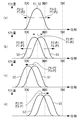
- FIG. 7 is a diagram showing a phase control example of the phase varying device 100A with the valve characteristics of the engine valves 51 and 52.
- FIG. 7 shows an example of phase control using (a) to (d).
- the vertical axis represents the valve lift amount
- the horizontal axis represents the phase.
- TDC indicates top dead center
- BDC indicates bottom dead center.
- the first cam C1 that drives the first engine valve 51 and the second cam C2 that drives the second engine valve 52 have the same cam profile.
- the present invention is not limited to this, and the cams C1 and C2 may have different cam profiles depending on, for example, required engine performance.
- the cams C1 and C2 are provided so as to operate in the same phase when the vanes 3c and 4b are in contact with each other.
- FIG. 7A shows an example of phase control when the phases of the engine valves 51 and 52 are simultaneously changed in the same phase.
- the phases of the engine valves 51 and 52 can be made the same phase.
- P1 larger than the hydraulic pressure P2
- P1> P2 the rotors 3 and 4
- the rotors 3 and 4 can be simultaneously advanced while the vane portions 3c and 4b are in contact with each other.
- the phases of the engine valves 51 and 52 can be advanced simultaneously with the same phase.
- the rotors 3 and 4 can be retarded simultaneously with the vanes 3c and 4b in contact with each other.
- the phases of the engine valves 51 and 52 can be retarded simultaneously with the same phase.
- the second hydraulic control valve 33A can be controlled so as to release the hydraulic pressure from the phase difference hydraulic chamber R3. Further, in order to make the hydraulic pressure P1 larger than the hydraulic pressure P2 (P1> P2), the hydraulic pressure is supplied to the advance hydraulic chamber R1, and the first hydraulic control valve 32 is set to release the hydraulic pressure from the retard hydraulic chamber R2. Can be controlled. On the other hand, in order to make the hydraulic pressure P1 smaller than the hydraulic pressure P2 (P1 ⁇ P2), the hydraulic pressure is released from the advance hydraulic chamber R1, and the first hydraulic control valve 32 is set so as to supply the hydraulic pressure to the retard hydraulic chamber R2. Can be controlled.
- FIG. 7B shows an example of phase control when the phase difference between the engine valves 51 and 52 is enlarged.
- the vanes 3c and 4b can be separated by supplying the hydraulic pressure P3.
- the phase difference between the engine valves 51 and 52 can be enlarged.
- the first engine valve 51 can be retarded and the second engine valve 52 can be advanced.
- Can be retarded As a result, among the engine valves 51 and 52, the phase of the engine valve 51 can be retarded.
- the first hydraulic control valve 32 is controlled so as to release the hydraulic pressure from the hydraulic chambers R1, R2, and the phase difference
- the second hydraulic control valve 33A can be controlled to supply hydraulic pressure to the hydraulic chamber R3.
- the hydraulic pressure is supplied to the advance hydraulic chamber R1, and the retard angle
- the first hydraulic control valve 32 can be controlled to release the hydraulic pressure from the hydraulic chamber R2, and the second hydraulic control valve 33A can be controlled to supply the hydraulic pressure to the phase difference hydraulic chamber R3.
- the hydraulic pressure is released from the advance hydraulic chamber R1 and is delayed.
- the first hydraulic control valve 32 can be controlled to supply hydraulic pressure to the angular hydraulic chamber R2, and the second hydraulic control valve 33A can be controlled to supply hydraulic pressure to the phase difference hydraulic chamber R3.
- FIG. 7C shows an example of phase control when the phase of the engine valves 51 and 52 is advanced simultaneously while maintaining the phase difference.
- the hydraulic pressure P1 is set larger than the hydraulic pressure P2 (P1> P2)
- the four phases can be advanced simultaneously.
- the phase of the engine valves 51 and 52 can be advanced simultaneously while maintaining the phase difference.
- the hydraulic pressure is supplied to the advanced hydraulic chamber R1 and the retarded hydraulic pressure is set.
- the first hydraulic control valve 32 can be controlled to release the hydraulic pressure from the chamber R2
- the second hydraulic control valve 33A can be controlled to release the hydraulic pressure from the phase difference hydraulic chamber R3.
- FIG. 7D shows an example of phase control in the case where the phases of the engine valves 51 and 52 are simultaneously retarded while maintaining the phase difference.
- the hydraulic pressure P2 is set larger than the hydraulic pressure P1 (P2> P1)
- the four phases can be retarded simultaneously.
- the phase of the engine valves 51 and 52 can be retarded simultaneously while maintaining the phase difference.
- the hydraulic pressure is released from the advance hydraulic chamber R1 and the retard hydraulic chamber
- the first hydraulic control valve 32 can be controlled to supply the hydraulic pressure to R2, and the second hydraulic control valve 33A can be controlled to release the hydraulic pressure from the phase difference hydraulic chamber R3.
- the first hydraulic control valve 32 can be controlled so as to supply the hydraulic pressure to the hydraulic chambers R1 and R2.
- the second hydraulic control valve 33A can be controlled so as to further supply the hydraulic pressure to the hydraulic chamber R3.
- the phase varying device 100A includes a phase varying unit 1A having hydraulic chambers R1, R2, and R3 in a single housing 2. Therefore, the phase varying device 100A can be configured to be advantageous for downsizing because the number of hydraulic chambers is suppressed to three when performing phase control of the cam shaft 10 having a double structure. Further, the configuration in which the phase control of the camshaft 10 is performed by the single phase variable portion 1A, and the configuration in which the overall length in the axial direction can be suppressed can be made advantageous for downsizing. Further, the configuration in which the phase control of the camshaft 10 is controlled by the single phase variable portion 1A can be made cost-effective.
- the phase varying device 100A has three hydraulic chambers, hydraulic chambers R1, R2, and R3, so that the number of hydraulic passage portions and grooves required for supplying hydraulic pressure from the outside of the phase variable portion 1A can be determined by the hydraulic passage portion L1. , L2 and L3 and groove portions D1, D2 and D3. For this reason, it can be set as the structure advantageous for compactness also by this.
- the phase varying device 100A controls the phase of the camshaft 10 with one phase varying unit 1A. For this reason, the phase control of the camshaft 10 can be avoided from being complicated in configuration. In addition, since the phase variable portion 1A receives the torque reaction force of the inner shaft 11 and the outer shaft 12, the influence of the torque fluctuation of the entire cam shaft 10 can be suppressed. As a result, the phase controllability of the cam shaft 10 can be improved.
- phase varying device 100A hydraulic chambers R1, R2, and R3 are arranged along the circumferential direction of the camshaft 10, and constitute a pair of hydraulic chambers R1, R2, and R3 that interact with each other. For this reason, the phase varying device 100A does not require a separate wall portion for partitioning the hydraulic chambers R1, R2, and R3 between the pair of hydraulic chambers R1, R2, and R3 that interact with each other. You can also. Further, the phase varying device 100A has a plurality of sets of hydraulic chambers R1, R2, and R3, so that the torque fluctuation of the camshaft 10 can be suitably suppressed.
- phase variable device 100A a housing into which a driving force for driving the camshaft 10 is input by the first rotor 3 for driving the inner shaft 11 and the second rotor 4 for driving the outer shaft 12 by the phase varying unit 1A. 2 is sandwiched.
- the phase variable device 100A can be configured to be advantageous in terms of cost because it has a simple configuration with a small number of parts and a configuration that can be easily assembled to the camshaft 10.
- the phase variable portion 1A more specifically includes a housing vane portion 2d provided in the housing 2, a first vane portion 3c provided in the first rotor 3, and a second vane portion provided in the second rotor 4.
- 4b is disposed inside the hound 2 along the circumferential direction, and the advance hydraulic chamber R1 is adjacent along the circumferential direction between the housing vane portion 2d and the first vane portion 3c adjacent along the circumferential direction.
- the rotors 3 and 4 have sliding portions 3ab and 4ab with the housing 2 on the outer peripheral portions of the rotor main bodies 3a and 4a.
- the housing 2 is subjected to, for example, the tension of the chain that transmits the driving force, so that the force acts in the direction in which the cam shaft 10 is bent.
- the smooth operation of the rotors 3 and 4 may be impaired.
- the phase varying device 100A has the sliding portions 3ab and 4ab with the housing 2 on the outer peripheral portions of the rotor main bodies 3a and 4a having the maximum diameter, so that the surface pressure generated by the force can be suitably reduced. .
- the smooth operation of the rotors 3 and 4 can also be ensured.
- the phase varying device 100A includes a driving force input unit 2a at a position where the housing 2 overlaps the second rotor 4 in the axial direction.
- the second rotor 4 is a rotor that drives the outer shaft 12 of which the bearing is provided between the cam shaft 10 and the engine 50.
- the phase varying device 100A can suppress the influence of the bending load by applying a load to the second rotor 4. As a result, it is possible to suitably suppress the cam shaft 10 from being misaligned at the position corresponding to the driving force input portion 2a in the axial direction and the operation of the inner shaft 11 from being affected.
- the phase varying device 100 ⁇ / b> A is configured to be provided on the camshaft 10 from the second rotor 4 side of the rotors 3 and 4. For this reason, the phase varying apparatus 100A can more suitably suppress the influence of the bending load.
- the phase varying device 100A includes a flange portion 11c provided on the inner shaft 11 so as to be sandwiched between the second rotor 4 and the outer shaft 12 in the axial direction in a state where the phase varying portion 1A is provided on the cam shaft 10. ing. Therefore, the phase varying device 100A can regulate the position of the inner shaft 11 in the axial direction with respect to the outer shaft 12 with the phase varying portion 1A provided on the cam shaft 10.
- the phase varying device 100A can simultaneously perform the positioning in the axial direction between the inner shaft 11 and the outer shaft 12 and the positioning in the axial direction between the rotors 3 and 4 at the flange portion 11c. As a result, it is possible to easily set the axial clearance for the vane portions 2d, 3c, and 4b. As a result, leakage of hydraulic oil from the hydraulic chambers R1, R2, and R3 can be suitably suppressed. Further, when the phase variable portion 1A is provided on the camshaft 10, positioning in the axial direction is simultaneously performed, so that the assembly to the camshaft 10 can be facilitated.
- the phase varying device 100A further includes knock pins 23 and 24, so that when the phase varying unit 1A is provided on the cam shaft 10, the positioning in the circumferential direction between the inner shaft 11 and the first rotor 3 and the outer shaft 12 are performed. And the circumferential positioning between the second rotors 4 can be performed simultaneously. As a result, when the phase variable portion 1A is provided on the camshaft 10, positioning in the axial direction and the circumferential direction is simultaneously performed, so that the assembly to the camshaft 10 can be facilitated.
- the phase varying device 100A includes, among the inner shaft 11 and the outer shaft 12, hydraulic passage portions L1, L2, and L3 that individually communicate with the hydraulic chambers R1, R2, and R3 inside the outer shaft 12.
- the hydraulic passage portions L1, L2, and L3 are prevented from being provided from the outer shaft 12 to the inner shaft 11.
- the phase varying device 100 ⁇ / b> A can further prevent the hydraulic oil from leaking into the clearance between the inner shaft 11 and the outer shaft 12.
- FIG. 8 is an overall configuration diagram of the phase variable device 100B.
- FIG. 9 is a first cross-sectional view of the phase variable section 1B.
- FIG. 10 is a second cross-sectional view of the phase variable unit 1B.
- FIG. 9 shows the phase variable portion 1B in a cross section including the central axis.
- FIG. 10 shows the phase variable portion 1B in a cross section orthogonal to the central axis.
- FIG. 9 shows the phase variable portion 1B in a cross section corresponding to the AA cross section shown in FIG.
- the phase variable device 100B is substantially the same as the phase variable device 100A except that the phase variable device 100B includes a phase variable unit 1B instead of the phase variable unit 1A.
- the phase variable unit 1B is substantially the same as the phase variable unit 1A except that the phase variable unit 1B further includes a first lock mechanism 5 and a second lock mechanism 6.
- the structure which has a change according to this it shows with the code
- the first lock mechanism 5 includes a first lock pin 5a, a first accommodating portion 5b, a first spring 5c, and a first engaging portion 5d.
- the second lock mechanism 6 includes a second lock pin 6a, a second accommodating portion 6b, a second spring 6c, and a second engaging portion 6d.
- the lock mechanisms 5 and 6 have the same structure. For this reason, here, the first lock mechanism 5 will be mainly described.
- the first lock pin 5a restrains the relative movement between the rotors 3 ′ and 4 ′ so as to be released.
- the 1st accommodating part 5b accommodates the 1st lock pin 5a so that sliding is possible along an axial direction.
- the first spring 5c biases the first lock pin 5a in a direction that restrains the relative movement between the rotors 3 'and 4'.
- the first lock pin 5a is engaged with the first engagement portion 5d, and the relative operation between the rotors 3 'and 4' is restricted.
- the first lock mechanism 5 is provided over the rotors 3 ′ and 4 ′.
- the first accommodating portion 5b is provided in the first rotor 3 ′ (specifically, one first vane portion 3c ′).
- the first engagement portion 5d is provided in the rotor 4 '(specifically, the main body portion 4a').
- the 1st accommodating part 5b can be provided in one of rotor 3 ', 4'. At this time, the first engaging portion 5d can be provided on the other of the rotors 3 'and 4'.
- the length of the first lock pin 5a is set to be equal to the length of the first accommodating portion 5b in the axial direction.
- the 1st lock pin 5a is provided with the accommodating part which can accommodate the 1st spring 5b in the bottom part side.
- the first spring 5c is provided in the first housing portion 5b and biases the first lock pin 5a toward the first engagement portion 5d.
- the first engagement portion 5d communicates with the phase difference hydraulic chamber R3 and applies hydraulic pressure to the first lock pin 5a in a direction to release the constraint between the rotors 3 ′ and 4 ′.
- the first engaging portion 5d can be communicated with the adjacent phase difference hydraulic chamber R3 via a communication path on the bottom side, for example.
- the second lock pin 6a restrains the relative movement between the housing 2 'and the first rotor 3' so that it can be released. For this reason, the second locking mechanism 6 is provided over the housing 2 ′ and the first rotor 3 ′.
- the second accommodating portion 6b is provided in the housing 2 ′ (specifically, one housing vane portion 2d ′).
- the second engagement portion 6d is provided in the first rotor 3 '(specifically, the main body portion 3a'). In the case of the second lock mechanism 6, the second engagement portion 6d communicates with the advance hydraulic chamber R1, and releases the restraint between the housing 2 'and the first rotor 3' with respect to the second lock pin 6a. Apply hydraulic pressure in the direction.
- the operation of the lock mechanisms 5 and 6 will be described.
- the operations of the lock mechanisms 5 and 6 are basically the same. Therefore, here, the operation will be mainly described by taking the first lock mechanism 5 as an example.
- the predetermined state is, for example, a state in which the relative phase of the second rotor 4 ′ with respect to the first rotor 3 ′ is most retarded.
- the predetermined state is a state where the relative phase of the first rotor 3 'with respect to the housing 2' is most retarded.
- a force acts on the first lock pin 5 a from the first housing portion 5 b side and the first engagement portion 5 d side.
- the force acting from the first accommodating portion 5b side is, for example, the urging force of the first spring 5c
- the force acting from the first engaging portion 5d side is, for example, a force corresponding to the hydraulic pressure P3 of the phase difference hydraulic chamber R3. It is.
- the first lock pin 5a receives the first accommodation.
- the force acting from the part 5b side is larger than the force acting from the first engaging part 5d side.
- the 1st lock pin 5a protrudes in the 1st engaging part 5d.
- the predetermined pressure can be set to a size that can distinguish whether or not the hydraulic pressure is supplied to the phase difference hydraulic chamber R3.
- the first lock pin 5a that operates in this manner is provided so as to operate according to the oil pressure P3 of the phase difference hydraulic chamber R3 when the relative phase between the rotors 3 'and 4' is in a predetermined state. It has been. Further, the first lock pin 5a that operates in this way restricts the relative operation between the rotors 3 'and 4' when the hydraulic pressure P3 is lower than a predetermined pressure, thereby allowing the volume of the phase difference hydraulic chamber R3 to be increased. The relative movement between the rotors 3 ′ and 4 ′ can be restricted in a predetermined state when the value is small, including the case where is zero.
- the second lock pin 6a is set to the hydraulic pressure P1 of the advance hydraulic chamber R1 when the relative phase between the housing 2 'and the first rotor 3' is in a predetermined state. It is provided to act accordingly.
- the second lock pin 6a restrains the relative movement between the housing 2 'and the first rotor 3' when the hydraulic pressure P1 is lower than a predetermined pressure, so that the volume of the advance hydraulic chamber R1 is increased.
- movement between housing 2 'and 1st rotor 3' can be restrained in a predetermined state.
- the first lock pin 5a is a restraint portion (first restraint portion) that restrains the relative movement between the rotors 3 'and 4' so as to be releasable
- the second lock pin 6a is a housing 2 'and a first This corresponds to a restraining portion (second restraining portion) that restrains the relative movement between the rotors 3 ′ so as to be releasable.
- the phase varying device 100B In the phase varying device 100B, the first lock pin 5a restrains the relative operation between the rotors 3 ′ and 4 ′ so as to be released. For this reason, the phase varying device 100B restricts the relative operation between the rotors 3 ′ and 4 ′ with the first lock pin 5a, so that a difference in torque and a difference in friction acting on the inner shaft 11 and the outer shaft 12 can be achieved. Unnecessary operations of the rotors 3 ′ and 4 ′ that can occur in response to the above can be restricted. As a result, the collision between the adjacent vane portions 3c (or 3c ′) and 4b can be avoided. Moreover, the phase controllability in the case where the phases of the rotors 3 ′ and 4 ′ are simultaneously changed can be improved by reliably operating the rotors 3 ′ and 4 ′ as a unit.
- the phase varying device 100B has a first lock pin that operates according to the hydraulic pressure P3 of the phase difference hydraulic chamber R3 when the relative phase between the rotors 3 ′ and 4 ′ is in a predetermined state. 5a is provided.
- the phase varying device 100B can specifically avoid the collision between the adjacent vane portions 3c (or 3c ′) and 4b when the volume of the phase difference hydraulic chamber R3 is small, for example. it can.
- the adjacent vane portions 3c (or 3c ′) and 4b are more likely to collide with each other as the volume of the phase difference hydraulic chamber R3 is smaller.
- the second lock pin 6a further restrains the relative movement between the housing 2 ′ and the first rotor 3 ′ so as to be released. For this reason, the phase varying device 100B restrains the relative movement between the housing 2 ′ and the first rotor 3 ′ with the second lock pin 6a at the start of the engine 50, for example, so that the housing 50 It is also possible to avoid a collision between 2 ′, the first rotor 3 ′ and the second rotor 4 ′.
- the phase varying device 100B can improve the startability of the engine 50 as follows.
- the relative operation between the housing 2 ′ and the first rotor 3 ′ is restricted in a state where the relative phase of the first rotor 3 ′ is most retarded with respect to the housing 2 ′.
- the intake air amount at the time of starting the engine 50 can be secured, and thereby the startability of the engine 50 can be improved.
- the relative phase between the housing 2 ′ and the first rotor 3 ′ is the most retarded relative phase of the first rotor 3 ′ with respect to the housing 2 ′, This can be achieved by providing the second lock pin 6a so as to operate according to the hydraulic pressure P1 of the advance hydraulic chamber R1.
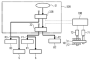
- FIG. 11 is an overall configuration diagram of the phase variable device 100C.
- FIG. 12 is a diagram showing a hydraulic circuit configuration of the phase varying device 100C.
- the phase variable device 100C is substantially the same as the phase variable device 100B except that it includes a hydraulic circuit unit 30B instead of the hydraulic circuit unit 30A and an ECU 70B instead of the ECU 70A.
- the hydraulic circuit unit 30B includes a pump 31, a first hydraulic control valve 32, and a second hydraulic control valve 33B.
- the first hydraulic control valve 32 is connected to the advance hydraulic chamber R1 and the retard hydraulic chamber R2, and is configured to control the supplied hydraulic pressure.
- the second hydraulic control valve 33B is connected to the first hydraulic control valve 32 and the phase difference hydraulic chamber R3, and is configured to control the hydraulic pressure to be supplied. For this reason, the second hydraulic control valve 33 ⁇ / b> B is arranged in series with respect to the first hydraulic control valve 32.
- the pump 31 is connected to the second hydraulic control valve 33B.
- the second hydraulic control valve 33B can be configured to supply hydraulic pressure to one of the first hydraulic control valve 32 and the phase difference hydraulic chamber R3. In this case, the hydraulic pressure can be released from the other side.
- the second hydraulic control valve 33B can be further configured to supply hydraulic pressure to the first hydraulic control valve 32 and the phase difference hydraulic chamber R3. Further, the hydraulic pressure can be released from each of the first hydraulic control valve 32 and the phase difference hydraulic chamber R3.
- the ECU 70B controls the phase of the camshaft 10 by controlling the hydraulic control valves 32 and 33B.
- the phases of the engine valves 51 and 52 are controlled.
- the hydraulic control valves 32 and 33B can be controlled as follows. That is, for example, when the engine 50 is started, the first hydraulic control valve 32 can be controlled so as to supply the hydraulic pressure to the retarded hydraulic chamber R2. Further, the second hydraulic control valve 33B can be controlled so as to supply the hydraulic pressure to the first hydraulic control valve 32.
- the hydraulic pressure P2 can be increased when the engine 50 is started, and the hydraulic pressures P1 and P3 can be made zero. For this reason, the phase of the second rotor 4 ′ with respect to the first rotor 3 ′ can be in the most retarded state. Further, the phase of the first rotor 3 ′ with respect to the housing 2 ′ can be in the most retarded state.
- the first hydraulic control valve 32 can be controlled so as to control the hydraulic pressure in the hydraulic chambers R2, R3 according to the load of the engine 50.
- the second hydraulic control valve 33B can be controlled so as to supply the hydraulic pressure to the first hydraulic control valve 32.
- the first hydraulic control valve 32 supplies hydraulic pressure to the advance hydraulic chamber R1 when the load of the engine 50 is switched from a medium load (for example, partial load) to a high load (for example, full load). Can be controlled. Further, when the load of the engine 50 is switched from a high load to a medium load, it can be controlled to supply hydraulic pressure to the retarded hydraulic chamber R2. Further, in each case, control can be performed so that the hydraulic pressure is supplied to each of the hydraulic chambers R1 and R2 based on the phases of the inner shaft 11 and the outer shaft 12.
- the hydraulic pressure P1 can be made higher than the hydraulic pressure P2 while the hydraulic pressure P3 is zero.
- the engine valves 51 and 52 can be advanced simultaneously in the same phase.
- the hydraulic pressure P2 can be made higher than the hydraulic pressure P1 while the hydraulic pressure P3 is zero.
- the hydraulic pressure P1 and the hydraulic pressure P2 can be made equal by supplying the hydraulic pressure to the hydraulic chambers R1 and R2. As a result, the phases of the engine valves 51 and 52 can be positioned simultaneously.
- the first lock pin 5a can restrain the relative operation between the rotors 3 'and 4' when the engine 50 is started.
- the second lock pin 6a can release the restraint between the housing 2 'and the first rotor 3' when the load of the engine 50 is switched from a medium load to a high load after the engine 50 is started.
- the engine valves 51 and 52 can be simultaneously changed in the same phase. In this case, the output performance of the engine 50 can be ensured.
- the phase varying device 100C is configured such that the first hydraulic control valve 32 is connected to the advance hydraulic chamber R1 and the retard hydraulic chamber R2 to control the supplied hydraulic pressure.
- the second hydraulic control valve 33B is connected to the first hydraulic control valve 32 and the phase difference hydraulic chamber R3, and is configured to control the hydraulic pressure to be supplied.
- the phase varying device 100C can simultaneously coordinate the hydraulic pressure P1 and the hydraulic pressure P2 with the first hydraulic control valve 32, for example, when positioning the phase. Further, at least one of the hydraulic pressures P1 and P2 and the hydraulic pressure P3 can be coordinated simultaneously by the second hydraulic control valve 33B. For this reason, the phase variable device 100C can prevent the occurrence of a hydraulic pressure deviation among the hydraulic chambers R1, R2, and R3, for example, when positioning the phase. As a result, the phase control can be more suitably performed.
- the phase varying device 100C can position the phase while coordinating the hydraulic pressures P1 and P2 by supplying the hydraulic pressures to the hydraulic chambers R1 and R2 by the first hydraulic control valve 32, respectively. Further, by supplying hydraulic pressure to the first hydraulic control valve 32 and the phase difference hydraulic chamber R3 by the second hydraulic control valve 33B, at least one of the hydraulic pressures P1 and P2 and the hydraulic pressure P3 are coordinated, Phase positioning can be performed.
- FIG. 13 is an overall configuration diagram of the phase variable device 100D.
- 14 (a) to 14 (c) are diagrams showing the hydraulic circuit configuration of the phase varying device 100D.
- FIG. 14A shows a first switching example of the hydraulic circuit unit 30C
- FIG. 14B shows a second switching example
- FIG. 14C shows a third switching example.
- 14 (a) to 14 (c) a hydraulic path indicated by a solid line indicates a hydraulic path through which the three-way valves 35 and 36 communicate.
- a hydraulic path indicated by a broken line indicates a hydraulic path where the three-way valves 35 and 36 are not in communication.
- the phase varying device 100D is substantially the same as the phase varying device 100C except that it includes a hydraulic circuit unit 30C instead of the hydraulic circuit unit 30B and also includes an ECU 70C instead of the ECU 70B.
- the hydraulic circuit unit 30C includes a third hydraulic control valve 34, a first three-way valve 35, and a second three-way valve 36.
- the first three-way valve 35 is connected to the advance hydraulic chamber R1 and the retard hydraulic chamber R2, and switches the hydraulic pressure supply destination.
- the second three-way valve 36 is connected to the retarded hydraulic chamber R2 and the phase difference hydraulic chamber R3, and switches the hydraulic pressure supply destination.
- the third hydraulic control valve 34 is connected to the three-way valves 35 and 36 and controls the hydraulic pressure to be supplied.
- the third hydraulic control valve 34 performs duty control on the hydraulic pressure supplied between the first three-way valve 35 side and the second three-way valve 36 side. Specifically, the third hydraulic control valve 34 allows the hydraulic pressure to be adjusted from one side of the first three-way valve 35 side and the second three-way valve 36 side, and the other side accordingly. It can be configured to supply hydraulic pressure. After that, the hydraulic pressure can be the same between the first three-way valve 35 side and the second three-way valve 36 side.
- the hydraulic circuit unit 30C can be separately supplied with hydraulic pressure in order to maintain the hydraulic pressure in the hydraulic circuit unit 30C.
- the ECU 70C controls the phase of the camshaft 10 by controlling the third hydraulic control valve 34 and the three-way valves 35 and 36.
- the phases of the engine valves 51 and 52 are controlled.
- the third hydraulic control valve 34 and the three-way valves 35 and 36 can be controlled as follows.
- the first three-way valve 35 is controlled so that the third hydraulic control valve 34 communicates with the advance hydraulic chamber R1, and the third hydraulic control valve 34 is also controlled.
- the retarded hydraulic chamber R2 can be controlled to control the second three-way valve 36.
- the first three-way valve 35 is controlled so as to communicate the third hydraulic control valve 34 with the advance hydraulic chamber R1 and the retard hydraulic chamber R2, and the first The second three-way valve 36 can be controlled so that the third hydraulic control valve 34 communicates with the phase difference hydraulic chamber R3.
- the first three-way valve 35 is controlled so that the third hydraulic control valve 34 communicates with the advance hydraulic chamber R1, and the third hydraulic control valve 34 is also provided.
- the second three-way valve 36 can be controlled so that the retard hydraulic chamber R2 and the phase difference hydraulic chamber R3 communicate with each other.
- the engine valves 51 and 52 can be advanced.
- the second engine valve 52 can be relatively retarded with respect to the first engine valve 51, the phase difference between the engine valves 51 and 52 can be reduced.
- the phase of the first engine valve 51 can be advanced while the second engine valve 52 is most advanced, and the phase difference between the engine valves 51 and 52 can be reduced.
- the first three-way valve 35 side and the second three-way valve 36 side have the same hydraulic pressure, Can be switched.
- the hydraulic pressure balance between the hydraulic chambers R1, R2, and R3 can be prevented from changing before and after switching.
- the phase of the engine valves 51 and 52 can be prevented from changing before and after switching.
- the phase of the engine valves 51 and 52 is prevented from changing by switching the hydraulic path to the retarded hydraulic chamber R2 where the torque reaction force from the camshaft 10 is not applied among the hydraulic chambers R1 and R2. Can do.
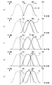
- FIG. 15 (a) to 15 (e) are diagrams showing examples of phase control of the phase variable device 100D by the valve characteristics of the engine valves 51 and 52.
- FIG. FIG. 15A shows a phase control example corresponding to FIG.
- FIGS. 15B, 15C, and 15E show examples of phase control corresponding to FIG. 14B
- FIG. 15D shows examples of phase control corresponding to FIG. 14C.
- 15A to 15E the vertical axis indicates the valve lift amount, and the horizontal axis indicates the phase.
- the valve characteristics of the exhaust valve are simultaneously shown by broken lines.
- the engine valves 51 and 52 can be advanced or retarded simultaneously in the same phase.
- the phase state shown in FIG. 15A is changed to the switching state shown in FIG. 14B
- the phase of the first engine valve 51 is retarded as shown in FIG.
- the phase between the engine valves 51 and 52 can be expanded by advancing the phase of the engine valve 52.
- the switching state shown in FIG. 14B when the phase of the second engine valve 52 is the most advanced as shown in FIG. 15C (the valve opening timing is the phase e1).
- the first engine valve 51 can be retarded from this state, and the phase between the engine valves 51 and 52 can be expanded.
- phase of the first engine valve 51 is advanced as shown in FIG.
- the phase difference between 52 can be reduced.
- the phase of the first engine valve 51 is advanced as shown in FIG.
- the phase between the engine valves 51 and 52 can be reduced.
- phase varying device 1 ⁇ / b> D can control the phase of the camshaft 10 with one third hydraulic control valve 34. For this reason, when the phase varying device 100D controls the camshaft 10, it is possible to avoid complication of phase control of the camshaft 10 as compared with a case where a plurality of hydraulic control valves are provided, for example.
Landscapes
- Engineering & Computer Science (AREA)
- Mechanical Engineering (AREA)
- General Engineering & Computer Science (AREA)
- Chemical & Material Sciences (AREA)
- Combustion & Propulsion (AREA)
- Valve Device For Special Equipments (AREA)
Abstract
Description
ハウジング 2、2´
第1のロータ 3、3´
第2のロータ 4、4´
第1のロックピン 5a
第2のロックピン 6a
カム軸 10
内軸 11
外軸 12
油圧回路部 30A、30B、30C
ポンプ 31
第1の油圧制御弁 32
第2の油圧制御弁 33A、33B
第3の油圧制御弁 34
第1の三方弁 35
第2の三方弁 36
エンジン 50
第1の機関弁 51
第2の機関弁 52
ECU 70A、70B、70C
位相可変装置 100A、100B、100C、100D
Claims (10)
- 入力される駆動力に応じて回転するとともに、内軸と外軸とからなる二重構造のカム軸に対して設けられ、
液圧によって前記カム軸の位相を全体的に進角させる進角液圧室と、液圧によって前記カム軸の位相を全体的に遅角させる遅角液圧室と、液圧によって前記内軸および前記外軸間の位相差を変更するための位相差液圧室と、を単一のハウジング内に有する位相可変部を備えるカム軸の位相可変装置。 - 請求項1記載のカム軸の位相可変装置であって、
前記進角液圧室、前記遅角液圧室および前記位相差液圧室が、前記カム軸の周方向に沿って配置され、互いに作用し合う一組の液圧室を構成しているカム軸の位相可変装置。 - 請求項1または2記載のカム軸の位相可変装置であって、
前記位相可変部が、前記ハウジングとして前記カム軸を駆動する駆動力が入力されるハウジングを備えるとともに、前記内軸を駆動する第1のロータと、前記外軸を駆動する第2のロータとを備え、前記第1および第2のロータで前記ハウジングを挟み込むようにして構成されているカム軸の位相可変装置。 - 請求項3記載のカム軸の位相可変装置であって、
前記第1および第2のロータが、前記第1および第2のロータが備えるロータ本体それぞれの外周部に前記ハウジングとの摺動部を有するカム軸の位相可変装置。 - 請求項3または4記載のカム軸の位相可変装置であって、
前記ハウジングが軸方向において前記第2のロータと重なる位置に前記駆動力が入力される駆動力入力部を備えるカム軸の位相可変装置。 - 請求項3から5いずれか1項記載のカム軸の位相可変装置であって、
前記位相可変部を前記カム軸に設けた状態で、軸方向において前記第2のロータと前記外軸とによって挟み込まれるように設けられる鍔部を前記内軸に備えるカム軸の位相可変装置。 - 請求項3から6いずれか1項記載のカム軸の位相可変装置であって、
前記内軸および前記外軸のうち、前記外軸の内部に前記進角液圧室、前記遅角液圧室および前記位相差液圧室に個別に連通する液圧通路部を備えるカム軸の位相可変装置。 - 請求項3から7いずれか1項記載のカム軸の位相可変装置であって、
前記位相可変部が前記第1および第2のロータ間の相対的な動作を解除可能に拘束する拘束部をさらに備えるカム軸の位相可変装置。 - 請求項1から8いずれか1項記載のカム軸の位相可変装置であって、
前記進角液圧室と前記遅角液圧室とに接続され、供給する液圧を制御する第1の液圧制御弁と、
前記第1の液圧制御弁と前記位相差液圧室とに接続され、供給する液圧を制御する第2の液圧制御弁と、をさらに備えるカム軸の位相可変装置。 - 請求項1から9いずれか1項記載のカム軸の位相可変装置であって、
前記進角液圧室と前記遅角液圧室とに接続され、液圧の供給先を切り替える第1の三方弁と、
前記遅角液圧室と前記位相差液圧室とに接続され、液圧の供給先を切り替える第2の三方弁と、
前記第1および第2の三方弁に接続され、供給する液圧を制御する液圧制御弁と、をさらに備えるカム軸の位相可変装置。
Priority Applications (7)
| Application Number | Priority Date | Filing Date | Title |
|---|---|---|---|
| RU2012107230/06A RU2560860C2 (ru) | 2011-03-31 | 2011-03-31 | Фазоизменяющее устройство для распределительного вала |
| JP2012507211A JP5263448B2 (ja) | 2011-03-31 | 2011-03-31 | カム軸の位相可変装置 |
| US13/394,065 US8695545B2 (en) | 2011-03-31 | 2011-03-31 | Phase changing device of camshaft |
| CN201180003682.6A CN102822453B (zh) | 2011-03-31 | 2011-03-31 | 凸轮轴的相位改变装置 |
| KR1020127005489A KR101353800B1 (ko) | 2011-03-31 | 2011-03-31 | 캠축의 위상 가변 장치 |
| EP11815662.9A EP2693003B1 (en) | 2011-03-31 | 2011-03-31 | Camshaft phase variable device |
| PCT/JP2011/058311 WO2012132002A1 (ja) | 2011-03-31 | 2011-03-31 | カム軸の位相可変装置 |
Applications Claiming Priority (1)
| Application Number | Priority Date | Filing Date | Title |
|---|---|---|---|
| PCT/JP2011/058311 WO2012132002A1 (ja) | 2011-03-31 | 2011-03-31 | カム軸の位相可変装置 |
Publications (1)
| Publication Number | Publication Date |
|---|---|
| WO2012132002A1 true WO2012132002A1 (ja) | 2012-10-04 |
Family
ID=46929822
Family Applications (1)
| Application Number | Title | Priority Date | Filing Date |
|---|---|---|---|
| PCT/JP2011/058311 WO2012132002A1 (ja) | 2011-03-31 | 2011-03-31 | カム軸の位相可変装置 |
Country Status (7)
| Country | Link |
|---|---|
| US (1) | US8695545B2 (ja) |
| EP (1) | EP2693003B1 (ja) |
| JP (1) | JP5263448B2 (ja) |
| KR (1) | KR101353800B1 (ja) |
| CN (1) | CN102822453B (ja) |
| RU (1) | RU2560860C2 (ja) |
| WO (1) | WO2012132002A1 (ja) |
Cited By (2)
| Publication number | Priority date | Publication date | Assignee | Title |
|---|---|---|---|---|
| WO2013099695A1 (ja) * | 2011-12-27 | 2013-07-04 | 本田技研工業株式会社 | 動弁装置 |
| JP2019167895A (ja) * | 2018-03-23 | 2019-10-03 | いすゞ自動車株式会社 | 内燃機関の動弁装置 |
Families Citing this family (14)
| Publication number | Priority date | Publication date | Assignee | Title |
|---|---|---|---|---|
| RU2560860C2 (ru) * | 2011-03-31 | 2015-08-20 | Тойота Дзидося Кабусики Кайся | Фазоизменяющее устройство для распределительного вала |
| DE102011006691A1 (de) * | 2011-04-04 | 2012-10-04 | Schaeffler Technologies Gmbh & Co. Kg | Nockenwellenversteller |
| WO2013032842A1 (en) * | 2011-08-30 | 2013-03-07 | Borgwarner Inc. | Oil passage design for a phaser or dual phaser |
| JP5987756B2 (ja) * | 2013-04-01 | 2016-09-07 | トヨタ自動車株式会社 | 内燃機関の制御装置 |
| JP6194695B2 (ja) * | 2013-08-26 | 2017-09-13 | アイシン精機株式会社 | 弁開閉時期制御装置 |
| DE102014210073B4 (de) * | 2014-05-27 | 2017-11-02 | Schaeffler Technologies AG & Co. KG | Nockenwellenversteller |
| ES2637951B2 (es) * | 2016-04-15 | 2018-03-07 | Amadeo PEREZ FERNANDEZ | Sistema de control para motores de combustión interna |
| RU2626044C1 (ru) * | 2016-08-23 | 2017-07-21 | Открытое акционерное общество "АВТОВАЗ" | Двигатель внутреннего сгорания |
| US11193399B2 (en) | 2018-11-27 | 2021-12-07 | Borgwarner, Inc. | Variable camshaft timing assembly |
| US10954829B2 (en) | 2018-12-19 | 2021-03-23 | Borgwarner, Inc. | Oldham flexplate for concentric camshafts controlled by variable camshaft timing |
| US11280228B2 (en) | 2020-07-07 | 2022-03-22 | Borgwarner, Inc. | Variable camshaft timing assembly |
| US11905861B2 (en) | 2020-12-01 | 2024-02-20 | Schaeffler Technologies AG & Co. KG | Multi-camshaft phase adjusting system |
| DE102021114162B4 (de) | 2021-06-01 | 2022-12-08 | Schaeffler Technologies AG & Co. KG | Elektromechanischer Nockenwellenversteller |
| US11852054B2 (en) | 2021-09-17 | 2023-12-26 | Borgwarner Inc. | Variable camshaft timing system |
Citations (4)
| Publication number | Priority date | Publication date | Assignee | Title |
|---|---|---|---|---|
| JP2002054410A (ja) * | 2000-08-11 | 2002-02-20 | Honda Motor Co Ltd | エンジンの可変開角動弁装置 |
| JP2002180807A (ja) * | 2000-10-04 | 2002-06-26 | Yamaha Motor Co Ltd | 動弁装置の可変バルブタイミング機構 |
| JP2006105062A (ja) * | 2004-10-07 | 2006-04-20 | Fujitsu Ten Ltd | 機関のバルブ動作制御装置 |
| JP2009293567A (ja) * | 2008-06-06 | 2009-12-17 | Nippon Soken Inc | 内燃機関の動弁制御装置 |
Family Cites Families (10)
| Publication number | Priority date | Publication date | Assignee | Title |
|---|---|---|---|---|
| RU2052637C1 (ru) * | 1993-03-10 | 1996-01-20 | Юрий Александрович Желтов | Шестерня привода распределительного вала двигателя внутреннего сгорания |
| RU2102604C1 (ru) * | 1996-04-04 | 1998-01-20 | Сергей Борисович Лахонин | Устройство для регулирования фаз газораспределения двигателя внутреннего сгорания |
| GB2369175A (en) * | 2000-11-18 | 2002-05-22 | Mechadyne Plc | Variable phase coupling |
| DE102005040934A1 (de) | 2005-02-03 | 2006-08-17 | Mahle International Gmbh | Verstellbare Nockenwelle, insbesondere für Verbrennungsmotoren von Kraftfahrzeugen, mit einer hydraulischen Stelleinrichtung |
| GB2432645B (en) * | 2005-11-28 | 2010-12-29 | Mechadyne Plc | Variable phase drive coupling |
| DE102006024793A1 (de) | 2006-05-27 | 2007-11-29 | Mahle International Gmbh | Nockenwelle |
| JP4747158B2 (ja) * | 2007-12-11 | 2011-08-17 | 本田技研工業株式会社 | 位相制御手段を備える動弁装置 |
| GB2467333A (en) * | 2009-01-30 | 2010-08-04 | Mechadyne Plc | Single camshaft phaser and camshaft for i.c. engines |
| WO2012109013A2 (en) * | 2011-02-09 | 2012-08-16 | Borgwarner Inc. | Dual phasers assembled concentrically on a concentric camshaft system |
| RU2560860C2 (ru) * | 2011-03-31 | 2015-08-20 | Тойота Дзидося Кабусики Кайся | Фазоизменяющее устройство для распределительного вала |
-
2011
- 2011-03-31 RU RU2012107230/06A patent/RU2560860C2/ru active
- 2011-03-31 US US13/394,065 patent/US8695545B2/en active Active
- 2011-03-31 CN CN201180003682.6A patent/CN102822453B/zh not_active Expired - Fee Related
- 2011-03-31 EP EP11815662.9A patent/EP2693003B1/en not_active Not-in-force
- 2011-03-31 KR KR1020127005489A patent/KR101353800B1/ko active IP Right Grant
- 2011-03-31 WO PCT/JP2011/058311 patent/WO2012132002A1/ja active Application Filing
- 2011-03-31 JP JP2012507211A patent/JP5263448B2/ja not_active Expired - Fee Related
Patent Citations (4)
| Publication number | Priority date | Publication date | Assignee | Title |
|---|---|---|---|---|
| JP2002054410A (ja) * | 2000-08-11 | 2002-02-20 | Honda Motor Co Ltd | エンジンの可変開角動弁装置 |
| JP2002180807A (ja) * | 2000-10-04 | 2002-06-26 | Yamaha Motor Co Ltd | 動弁装置の可変バルブタイミング機構 |
| JP2006105062A (ja) * | 2004-10-07 | 2006-04-20 | Fujitsu Ten Ltd | 機関のバルブ動作制御装置 |
| JP2009293567A (ja) * | 2008-06-06 | 2009-12-17 | Nippon Soken Inc | 内燃機関の動弁制御装置 |
Non-Patent Citations (1)
| Title |
|---|
| See also references of EP2693003A4 * |
Cited By (5)
| Publication number | Priority date | Publication date | Assignee | Title |
|---|---|---|---|---|
| WO2013099695A1 (ja) * | 2011-12-27 | 2013-07-04 | 本田技研工業株式会社 | 動弁装置 |
| JPWO2013099695A1 (ja) * | 2011-12-27 | 2015-05-07 | 本田技研工業株式会社 | 動弁装置 |
| US9140151B2 (en) | 2011-12-27 | 2015-09-22 | Honda Motor Co., Ltd. | Valve gear |
| JP2019167895A (ja) * | 2018-03-23 | 2019-10-03 | いすゞ自動車株式会社 | 内燃機関の動弁装置 |
| JP7028010B2 (ja) | 2018-03-23 | 2022-03-02 | いすゞ自動車株式会社 | 内燃機関の動弁装置 |
Also Published As
| Publication number | Publication date |
|---|---|
| US20120279464A1 (en) | 2012-11-08 |
| KR20120130159A (ko) | 2012-11-29 |
| JP5263448B2 (ja) | 2013-08-14 |
| CN102822453A (zh) | 2012-12-12 |
| EP2693003A1 (en) | 2014-02-05 |
| KR101353800B1 (ko) | 2014-01-21 |
| RU2012107230A (ru) | 2015-05-10 |
| CN102822453B (zh) | 2015-08-05 |
| US8695545B2 (en) | 2014-04-15 |
| JPWO2012132002A1 (ja) | 2014-07-24 |
| RU2560860C2 (ru) | 2015-08-20 |
| EP2693003B1 (en) | 2016-04-27 |
| EP2693003A4 (en) | 2015-02-25 |
Similar Documents
| Publication | Publication Date | Title |
|---|---|---|
| JP5263448B2 (ja) | カム軸の位相可変装置 | |
| JP5585832B2 (ja) | 弁開閉時期制御装置 | |
| JP5876061B2 (ja) | 中間位置ロックを備えたカムトルク駆動型位相器 | |
| JP6373464B2 (ja) | 内燃機関のバルブタイミング制御装置 | |
| JP5403341B2 (ja) | 弁開閉時期制御装置 | |
| US6772721B1 (en) | Torsional assist cam phaser for cam in block engines | |
| US8453614B2 (en) | Variable valve timing device for internal combustion engine and manufacturing method therefor | |
| EP2990620B1 (en) | Valve timing control apparatus | |
| WO2014038267A1 (ja) | 弁開閉時期制御装置 | |
| JP2015028308A (ja) | 弁開閉時期制御装置 | |
| WO2016163119A1 (ja) | バルブタイミング調整装置 | |
| JP2006105062A (ja) | 機関のバルブ動作制御装置 | |
| JP6809176B2 (ja) | 弁開閉時期制御装置 | |
| JP6254711B2 (ja) | 内燃機関のバルブタイミング制御装置 | |
| JP6171731B2 (ja) | 制御弁 | |
| JP2014074379A (ja) | バルブタイミング調整装置 | |
| WO2015079961A1 (ja) | 弁開閉時期制御装置 | |
| JP5793116B2 (ja) | 内燃機関の可変動弁装置 | |
| JP2013245613A (ja) | 弁開閉時期制御装置 | |
| WO2015029476A1 (ja) | 弁開閉時期制御装置 | |
| JP2009257256A (ja) | バルブタイミング調整装置 | |
| JP6258828B2 (ja) | 内燃機関のバルブタイミング制御装置 | |
| JP5793107B2 (ja) | 内燃機関の可変動弁装置 | |
| JP5793115B2 (ja) | 内燃機関の可変動弁装置 | |
| JP6589342B2 (ja) | 弁開閉時期制御装置 |
Legal Events
| Date | Code | Title | Description |
|---|---|---|---|
| WWE | Wipo information: entry into national phase |
Ref document number: 201180003682.6 Country of ref document: CN |
|
| ENP | Entry into the national phase |
Ref document number: 2012507211 Country of ref document: JP Kind code of ref document: A |
|
| WWE | Wipo information: entry into national phase |
Ref document number: 372/MUMNP/2012 Country of ref document: IN Ref document number: 2011815662 Country of ref document: EP |
|
| ENP | Entry into the national phase |
Ref document number: 20127005489 Country of ref document: KR Kind code of ref document: A |
|
| WWE | Wipo information: entry into national phase |
Ref document number: 13394065 Country of ref document: US |
|
| 121 | Ep: the epo has been informed by wipo that ep was designated in this application |
Ref document number: 11815662 Country of ref document: EP Kind code of ref document: A1 |
|
| NENP | Non-entry into the national phase |
Ref country code: DE |
|
| ENP | Entry into the national phase |
Ref document number: 2012107230 Country of ref document: RU Kind code of ref document: A |