WO2012131979A1 - 画像処理装置、画像処理方法及び画像処理プログラム - Google Patents
画像処理装置、画像処理方法及び画像処理プログラム Download PDFInfo
- Publication number
- WO2012131979A1 WO2012131979A1 PCT/JP2011/058217 JP2011058217W WO2012131979A1 WO 2012131979 A1 WO2012131979 A1 WO 2012131979A1 JP 2011058217 W JP2011058217 W JP 2011058217W WO 2012131979 A1 WO2012131979 A1 WO 2012131979A1
- Authority
- WO
- WIPO (PCT)
- Prior art keywords
- parallax
- parallax amount
- amount
- image processing
- unit
- Prior art date
- Legal status (The legal status is an assumption and is not a legal conclusion. Google has not performed a legal analysis and makes no representation as to the accuracy of the status listed.)
- Ceased
Links
Images








Classifications
-
- G—PHYSICS
- G03—PHOTOGRAPHY; CINEMATOGRAPHY; ANALOGOUS TECHNIQUES USING WAVES OTHER THAN OPTICAL WAVES; ELECTROGRAPHY; HOLOGRAPHY
- G03B—APPARATUS OR ARRANGEMENTS FOR TAKING PHOTOGRAPHS OR FOR PROJECTING OR VIEWING THEM; APPARATUS OR ARRANGEMENTS EMPLOYING ANALOGOUS TECHNIQUES USING WAVES OTHER THAN OPTICAL WAVES; ACCESSORIES THEREFOR
- G03B35/00—Stereoscopic photography
- G03B35/18—Stereoscopic photography by simultaneous viewing
- G03B35/20—Stereoscopic photography by simultaneous viewing using two or more projectors
-
- H—ELECTRICITY
- H04—ELECTRIC COMMUNICATION TECHNIQUE
- H04N—PICTORIAL COMMUNICATION, e.g. TELEVISION
- H04N13/00—Stereoscopic video systems; Multi-view video systems; Details thereof
- H04N13/20—Image signal generators
- H04N13/204—Image signal generators using stereoscopic image cameras
- H04N13/239—Image signal generators using stereoscopic image cameras using two two-dimensional [2D] image sensors having a relative position equal to or related to the interocular distance
-
- H—ELECTRICITY
- H04—ELECTRIC COMMUNICATION TECHNIQUE
- H04N—PICTORIAL COMMUNICATION, e.g. TELEVISION
- H04N13/00—Stereoscopic video systems; Multi-view video systems; Details thereof
- H04N13/10—Processing, recording or transmission of stereoscopic or multi-view image signals
- H04N13/106—Processing image signals
- H04N13/128—Adjusting depth or disparity
-
- H—ELECTRICITY
- H04—ELECTRIC COMMUNICATION TECHNIQUE
- H04N—PICTORIAL COMMUNICATION, e.g. TELEVISION
- H04N13/00—Stereoscopic video systems; Multi-view video systems; Details thereof
- H04N13/10—Processing, recording or transmission of stereoscopic or multi-view image signals
- H04N13/106—Processing image signals
- H04N13/139—Format conversion, e.g. of frame-rate or size
Definitions
- the present invention relates to an image processing apparatus, an image processing method, and an image processing program for processing a stereoscopic video.
- zoom-in shooting it is natural that a subject is localized forward, and it is natural to adjust the amount of parallax.
- FIG. 1 is a diagram showing a relationship between zoom-in and a subject.
- FIG. 1A shows the relationship between the subjects 11 and 12 and the screen 13 before zooming in.
- the FO direction shown in FIG. 1A is a direction in which the subject jumps forward
- the BA direction is a direction in which the subject is drawn backward. Zoom in is performed on the stereoscopic video shown in FIG.
- FIG. 1 (B) shows the expected result for a stereoscopic image.
- the subject 11 appears to move in front of the screen 13.
- the measurement distance is limited to a short distance, and the mechanism for adjusting the parallax amount may not work depending on the distance to the subject.
- the distance measuring unit is provided, the cost of the conventional apparatus is increased.
- FIG. 1 (C) shows the result of the prior art.
- the amount of parallax is adjusted so that the subject 11 near the center is always visible on the screen 13 surface.
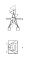
- FIG. 2 is a diagram for explaining dangerous images.
- FIG. 2A shows a video example of the t ⁇ 1 frame. It is assumed that the left subject 12 looks at the left subject 12 and the right eye looks at the right subject 12. As a result, the subject 12 appears behind the subject 11.
- FIG. 2B is an example of a t-frame image when the image is zoomed in by the conventional method from the state shown in FIG. As shown in FIG. 2B, the left subject 12 viewed with the left eye shifts to the left, and the right subject 12 viewed with the right eye shifts to the right. Note that the parallax amount of the subject 11 is adjusted to zero.
- the fact that a dangerous image is obtained will be described with an imaging system in which the left camera 31 and the right camera 32 are arranged substantially in parallel.
- the left camera 31 captures an image for the left eye
- the right camera 32 captures an image for the right eye.
- FIG. 2C shows the parallax relationship at the time of the t-1 frame.
- the subject 11 is present on the virtual screen 33 at the convergence point p34.
- the parallax amount of the subject 12 is set to d35.
- FIG. 2D shows the relationship of parallax at the time of t frame.
- the subject 11 continues to exist on the virtual screen 33 surface, and the background subject 12 moves backward as zooming in.
- the amount of parallax at this time is d36.
- the relationship d35 ⁇ d36 is established.
- the conventional image will be an image in which the amount of parallax increases when zooming in and both eyes are opened to the outside. Therefore, the prior art has a problem in that the amount of parallax cannot be appropriately adjusted during zooming and the quality of the stereoscopic video is not good.
- the disclosed technology has been made in view of the above-described problems, and an image processing device, an image processing method, and an image processing program that can appropriately adjust a parallax amount during zooming and generate a natural stereoscopic video.
- the purpose is to provide.
- An image processing apparatus is an image processing apparatus that processes stereoscopic video
- An enlargement / reduction ratio detection unit that detects an enlargement / reduction ratio from an enlarged or reduced stereoscopic image, an interval between a plurality of cameras at the time of shooting, a distance from the plurality of cameras to a convergence point, and a parallax amount at the convergence point
- a parallax amount calculation unit that calculates the parallax amount represented by the interval and the enlargement / reduction ratio using a similarity relationship based on the parallax amount, and the parallax amount of the stereoscopic video using the parallax amount calculated by the parallax amount calculation unit
- a parallax amount adjusting unit for adjusting the parallax.
- FIG. 1 is a block diagram illustrating an example of a configuration of an image processing device according to Embodiment 1.
- FIG. The figure for demonstrating the calculation example of the expansion / contraction rate (alpha).
- the block diagram which shows an example of a structure of a parallax amount calculation part.
- FIG. The figure for demonstrating the natural image
- FIG. 5 is a flowchart illustrating an example of image processing in the first embodiment.
- the flowchart which shows an example of the shift restriction
- the figure for demonstrating that the amount of parallax of an infinite point does not change.
- FIG. 6 is a block diagram illustrating an example of a configuration of an image processing apparatus according to a second embodiment. The figure which shows the relationship between a virtual screen surface and an actual screen surface. The figure which shows an example of the viewing distance in an actual screen. The figure which shows an example of the parallax amount d1. The figure which shows an example of ratio with a cumulative moving average value and an average value.
- FIG. 10 is a flowchart illustrating an example of image processing according to the second embodiment.
- FIG. 9 is a block diagram illustrating an example of a configuration of an image processing apparatus according to a third embodiment.
- 10 is a flowchart illustrating an example of image processing in the third embodiment.
- the block diagram which shows an example of a structure of the image processing apparatus in a modification.
- FIG. 3 is a block diagram illustrating an example of the configuration of the image processing apparatus 100 according to the first embodiment.
- the image processing apparatus 100 illustrated in FIG. 3 includes an enlargement / reduction ratio detection unit 101, a parallax amount calculation unit 102, and a parallax amount adjustment unit 103.
- the image processing apparatus 100 inputs the left image and the right image, and inputs the left and right images to the enlargement / reduction ratio detection unit 101 and the parallax amount adjustment unit 103.
- the left video and the right video may be stored in the image processing apparatus 100 or may be input from a plurality of imaging systems.
- the enlargement / reduction ratio detection unit 101 receives left and right images, and detects the enlargement / reduction ratio at the time of zooming in (enlarging) or zooming out (reducing) based on the left and right images.
- the detected scaling ratio is output to the parallax amount calculation unit 102.
- any known technique may be used as a method for detecting the enlargement / reduction ratio.
- JP-A-2005-332120 See JP-A-2005-332120.
- the ratio of time change with respect to the position interval of each peak code of both horizontal and vertical edge peak codes is defined as the scaling ratio.
- the enlargement / reduction ratio detection unit 101 may detect the enlargement / reduction ratio as follows, for example.
- FIG. 4 is a diagram for explaining an example of calculating the enlargement / reduction ratio ⁇ .
- the subject 11 is photographed by the left camera 31 and the right camera 32 shown in FIG. At this time, it is assumed that zooming in is performed and the position of the subject 11 is moved L2 in the camera direction from the distance L1 from the cameras 31 and 32 to the convergence point.
- D is a camera interval
- X is approximated by L1.
- X ′ is approximated by L1-L2.
- the parallax amount calculation unit 102 calculates an appropriate parallax amount d during zooming using the camera interval D and the enlargement / reduction ratio ⁇ .
- the parallax amount calculation unit 102 will be described with reference to FIG.
- FIG. 5 is a block diagram illustrating an example of the configuration of the parallax amount calculation unit 102.
- the parallax amount calculation unit 102 illustrated in FIG. 5 includes a multiplication unit 121 and a storage unit 122.
- the storage unit 122 stores an interval D between the left camera and the right camera.
- the storage unit 122 stores the interval D in advance or inputs and stores it in the image processing apparatus 100 during image processing.
- FIG. 6 is a diagram illustrating a relationship among the enlargement / reduction ratio ⁇ , the parallax amount d, and the camera interval D.
- a parallax amount d is generated in the subject 11 in the left and right images.
- D / 2: d / 2 L1-L2: L2 Formula (4)
- d L2 / (L1-L2) ⁇ D (5)
- equation (5) is modified to obtain equation (6).
- the parallax amount adjusting unit 103 acquires the parallax amount d from the parallax amount calculating unit 102.
- the parallax amount adjustment unit 103 adjusts the parallax amount of the left and right images to be d. For example, the parallax amount adjusting unit 103 shifts the left video to the left by a half (d / 2) of the parallax amount d, and shifts the right video to the right by a half (d / 2) the parallax amount d.
- the subject has a parallax amount d in the left and right images. Accordingly, a natural stereoscopic image can be generated by adjusting the left and right images with an appropriate amount of parallax during zooming.
- FIG. 7 is a diagram for explaining a natural image during zooming.
- the stereoscopic video is shifted so that the subject 11 has the calculated parallax amount d40.
- the subject 11 moves forward as shown in FIG. 7B, and the background subject 12 that has moved backward in the result of the prior art (FIG. 2) also moves forward, so that both eyes are not opened. effective.
- the parallax adjustment unit 103 may limit the amount of projection of the subject from the screen surface using the convergence angle when zooming in.
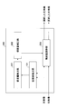
- FIG. 8 is a block diagram illustrating an example of the configuration of the parallax amount adjustment unit 103.
- the 8 includes a storage unit 131, a shift limiting unit 132, and a shift unit 133.
- the storage unit 131 stores the camera interval D between the right camera and the left camera.
- the shift restricting unit 132 restricts the amount of projection of the subject from the screen surface when zooming in using the convergence angle.
- the convergence angle ⁇ is calculated by the following equation (8) using L2 calculated by the deformation equation (7) of the expansion / contraction ratio ⁇ and the camera interval D.
- L1 may be calculated in advance based on camera parameters such as a camera angle, or may be set in advance.
- the shift limiter 132 does not shift the left and right images in order to prevent the subject from moving further before the calculated convergence angle ⁇ exceeds a certain value. Therefore, the shift limiting unit 132 outputs the parallax amount d to the shift unit 133 when the convergence angle ⁇ is less than a predetermined value, and does not output the parallax amount d to the shift unit 133 when the convergence angle ⁇ is greater than or equal to the predetermined value.
- the predetermined value is, for example, 1 degree. This 1 degree is a value based on the 3DC safety guidelines of the 3D consortium.
- the shift unit 133 shifts the left and right images in the horizontal direction using the parallax amount d acquired from the shift limiting unit 132.
- the amount to shift is d / 2 for each video.
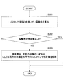
- FIG. 9 is a flowchart illustrating an example of image processing according to the first embodiment.
- step S101 shown in FIG. 9 the enlargement / reduction ratio detection unit 101 detects the enlargement / reduction ratio ⁇ from the video during zoom-in (enlargement) or zoom-out (reduction).
- a known method may be used for the expansion / contraction rate ⁇ .
- step S102 the parallax amount calculation unit 102 calculates the parallax amount d by multiplying the enlargement / reduction ratio ⁇ -1 by the camera interval D.
- step S103 the parallax adjustment unit 103 adjusts the parallax amount by shifting the left and right images in the horizontal direction by half the parallax amount d, for example.
- the video can be shifted by an appropriate amount of parallax during zooming, and a natural stereoscopic video can be generated.
- FIG. 10 is a flowchart illustrating an example of the shift limiting process of the parallax amount adjusting unit 103. The process shown in FIG. 10 may be performed in step S103 shown in FIG.
- step S201 the shift limiting unit 132 calculates the convergence angle ⁇ according to the equation (8) using L2 calculated from the equation of the enlargement / reduction ratio ⁇ and the camera interval D.
- step S202 the shift limiting unit 132 determines whether the calculated convergence angle ⁇ is equal to or greater than a predetermined value. If the convergence angle ⁇ is equal to or greater than the predetermined value (step S102—YES), this process is terminated, and if the convergence angle ⁇ is less than the predetermined value (step S102—NO), the process proceeds to step S203.
- step S203 the shift unit 133 adjusts the amount of parallax by shifting the amount of parallax, one of the left and right images, or both of the images in the horizontal direction by the total amount of parallax.
- parallax amount at infinity point in imaging system (Parallax amount at infinity point in imaging system)
- the parallax amount at the infinity point in the imaging system does not change.
- FIG. 11 is a diagram for explaining that the amount of parallax at the infinity point does not change. As shown in FIG. 11, the amount of parallax at the infinity point is the same as the camera interval D between the left camera 31 and the right camera 32, and becomes ⁇ D when zoomed in ⁇ times.
- parallax amount adjustment processing when zoomed out may be performed in the same manner as the parallax amount adjustment processing when zoomed in.
- the image processing apparatus 200 according to the second embodiment will be described.
- the parallax amount is corrected according to the actual screen width.
- the actual screen width is the width of the screen on which video is displayed.
- FIG. 12 is a block diagram illustrating an example of the configuration of the image processing apparatus 200 according to the second embodiment.
- An image processing apparatus 200 illustrated in FIG. 12 includes an enlargement / reduction ratio detection unit 101, a parallax amount calculation unit 201, a parallax amount correction unit 202, and a parallax amount adjustment unit 203. Since the enlargement / reduction ratio detection unit 101 has the same function as that of the first embodiment, description thereof is omitted.
- the parallax amount calculation unit 201 outputs the parallax amount d calculated in the same manner as in the first embodiment to the parallax amount correction unit 202.
- the parallax amount correcting unit 202 corrects the parallax amount in accordance with the actual width of the screen surface with respect to the acquired parallax amount d. At this time, the corrected parallax amount is set to d1.
- the parallax amount correction unit 202 obtains the parallax amount d1 by using the similar relationship between the virtual screen surface and the actual screen surface.
- FIG. 13 is a diagram showing the relationship between the virtual screen 51 surface and the actual screen 52 surface. As shown in FIG. 13, the virtual screen 51 surface and the actual screen 52 surface have a similar relationship.
- the width of the virtual screen 51 is W2, the amount of parallax is d, the width of the actual screen 52 is W1, and the corrected amount of parallax is d1.
- the following equation (10) holds.
- d: d1 W2: W1 (10)
- d1 d ⁇ (W1 / W2)
- the parallax amount correction unit 202 calculates the parallax amount d1 corrected by the equation (11).
- the calculated parallax amount d1 is output to the parallax amount adjusting unit 203.
- the virtual screen width W2 is calculated by the following equation (12).
- the parallax adjustment unit 203 uses the parallax amount d1 acquired from the parallax correction unit 202. The parallax amount between the left and right images is adjusted in the same manner as in the first embodiment.
- FIG. 14 is a diagram illustrating an example of a viewing distance on an actual screen. As shown in FIG. 14, the distance L3 is the distance from the implementation screen to the eyes.
- the viewing distance L3 is calculated by the following equation (13).
- L3 (1/2) ⁇ W1 / tan ( ⁇ 2 / 2) (13)
- W1 Actual screen surface width
- ⁇ 2 Horizontal reference angle of view
- the horizontal reference angle of view is determined by the angle at which eyes can view.
- FIG. 15 is a diagram illustrating an example of the parallax amount d1.
- ⁇ 1 39.6 degrees (35mm full-size digital single-lens reflex camera, focal length is 50 mm)
- W1 819mm (37-inch display)
- L1 10000 mm (set the convergence point at a position 10 m from the camera)
- D 65mm (general human eye width)
- the parallax amount correction unit 202 can calculate the corrected parallax amount d1 illustrated in FIG. 15 by changing the enlargement / reduction ratio ⁇ using Expressions (3), (11), and (12).
- the corrected parallax amount correction unit 202 outputs the corrected parallax amount d1 calculated according to the enlargement / reduction ratio ⁇ during zooming to the parallax amount adjustment unit 203.
- each subject appears at the position shown in FIG.
- the subject 11 appears at a position of 1.8 m in a direction protruding from the actual screen surface
- the subject 12 appears at a position of 2.2 m in the depth direction from the actual screen surface.
- each subject appears at the position shown in FIG.
- the subject 11 appears at a position of 1.8 mm in a direction protruding from the actual screen surface
- the subject 12 appears at a position of 32 mm in the depth direction from the actual screen surface.
- FIG. 18 is a flowchart illustrating an example of image processing according to the second embodiment.
- step S301 shown in FIG. 18 the enlargement / reduction ratio detection unit 101 detects the enlargement / reduction ratio ⁇ from the video during zoom-in (enlargement) or zoom-out (reduction).
- a known method may be used for the expansion / contraction rate ⁇ .
- step S302 the parallax amount calculation unit 201 calculates the parallax amount d by multiplying the enlargement / reduction ratio ⁇ -1 by the camera interval D.
- step S303 the parallax amount correction unit 202 corrects the parallax amount d according to the actual screen width, and calculates the corrected parallax amount d1.
- the corrected parallax amount d1 is calculated by Expression (11).
- step S304 the parallax amount adjustment unit 203 adjusts the parallax amount by shifting the left and right images horizontally by half of the corrected parallax amount d.
- the video can be shifted by an appropriate amount of parallax that matches the actual screen width, and a natural stereoscopic video can be generated.
- the parallax amount d2 at the infinity point in the display system is calculated by the following equation (14).
- d2 D ⁇ (W1 / W2) (14)
- D Camera interval
- W1 Actual screen surface width
- W2 Virtual screen surface width
- the parallax amount d3 at the infinity point taking into account the viewing distance is calculated by the following equation (15).
- the interocular distance D ' may be set to 65 mm, which is the width of a general human eye, for example.
- the second embodiment by calculating the shift amount of parallax based on the enlargement / reduction ratio and the actual screen width, for example, it is possible to generate a natural three-dimensional video in which the subject is localized forward when zooming in.
- parallax amount adjustment processing when zoomed out may be performed in the same manner as the parallax amount adjustment processing when zoomed in.
- Example 3 Next, the image processing apparatus 300 according to the third embodiment will be described.
- the optical axis shift is corrected and the correction amount is reflected in the camera interval.
- FIG. 19 is a block diagram illustrating an example of the configuration of the image processing apparatus 300 according to the third embodiment.
- An image processing apparatus 300 illustrated in FIG. 19 includes an optical axis deviation correction unit 301, an enlargement / reduction rate detection unit 302, a parallax amount calculation unit 303, and a parallax amount adjustment unit 304.
- the optical axis misalignment correction unit 301 shown in FIG. 19 measures the amount of optical axis misalignment between the lens and the image sensor, and corrects the left and right images using this amount of misalignment.
- a known technique may be used for optical axis misalignment correction.
- the optical axis deviation correction unit 301 outputs the horizontal correction amount d4 on the actual screen surface to the parallax amount calculation unit 303.
- the parallax amount calculation unit 303 corrects the camera interval D using the correction amount d4.
- the correction amount calculation unit 303 corrects the camera interval D using, for example, the following equation (17).
- the corrected camera interval is set to D1.
- D1 D + d4 ⁇ (W2 / W1) (17)
- the parallax amount calculation unit 303 calculates the parallax amount d5 by the equation (18) using the corrected camera interval D1 and the enlargement / reduction ratio ⁇ .
- d5 ( ⁇ 1) ⁇ D1 (18)
- the calculated parallax amount d5 is output to the parallax amount adjusting unit 304.
- the parallax amount adjusting unit 304 corrects the left and right images after the optical axis deviation correction using the parallax amount d5.
- the correction process is the same as the process described in the first embodiment.
- FIG. 20 is a flowchart illustrating an example of image processing according to the third embodiment.
- step S401 shown in FIG. 20 the optical axis deviation correction unit 301 corrects the deviation of the optical axes of the left and right images using a known technique.
- the correction amount in the horizontal direction is output to the parallax amount calculation unit 303.
- step S402 the enlargement / reduction ratio detection unit 302 detects the enlargement / reduction ratio ⁇ from the image after optical axis misalignment correction during zoom-in (enlargement) or zoom-out (reduction).
- a known method may be used for the expansion / contraction rate ⁇ .
- step S403 the parallax amount calculation unit 303 corrects the camera interval D by Expression (17) using the horizontal d4 corrected by the optical axis deviation correction unit 301.
- step S404 the parallax amount calculation unit 303 calculates the parallax amount d5 by multiplying the enlargement / reduction ratio ⁇ -1 by the corrected camera interval D1.
- step S405 the parallax adjustment unit 304 adjusts the parallax amount by shifting the left and right images in the horizontal direction by half of the parallax amount d5, for example.
- the parallax amount may be corrected in accordance with the actual screen width in the second embodiment.
- the shift limitation by the convergence angle in the first embodiment may be performed.
- the third embodiment by calculating the shift amount of parallax based on the enlargement / reduction ratio and the camera interval after correcting the optical axis shift, for example, it is possible to generate a natural three-dimensional image in which the subject is localized forward when zooming in.
- parallax amount adjustment processing when zoomed out may be performed in the same manner as the parallax amount adjustment processing when zoomed in.
- FIG. 21 is a block diagram illustrating an example of the configuration of the image processing apparatus 400 according to the modification.
- the image processing apparatus 400 includes a control unit 401, a main storage unit 402, an auxiliary storage unit 403, a drive device 404, an input unit 406, a display unit 407, and imaging units 408 and 409. These components are connected to each other via a bus so as to be able to transmit and receive data.
- the control unit 401 is a CPU that controls each device, calculates data, and processes in a computer.
- the control unit 401 is an arithmetic device that executes a program stored in the main storage unit 402 or the auxiliary storage unit 403.
- the control unit 401 receives data from the input unit 406 or the storage device, calculates and processes the data, and then displays the display unit 407. Or output to a storage device.
- control unit 401 executes an image processing program stored in the auxiliary storage unit 403 or the like, and performs the image processing described in the embodiment.
- the main storage unit 402 is a ROM (Read Only Memory), a RAM (Random Access Memory) or the like, and stores or temporarily stores programs and data such as OS (Operating System) and application software which are basic software executed by the control unit 401. It is a storage device to save.
- OS Operating System
- application software which are basic software executed by the control unit 401. It is a storage device to save.
- the auxiliary storage unit 403 is an HDD (Hard Disk Drive) or the like, and is a storage device that stores data related to application software.
- HDD Hard Disk Drive
- the drive device 404 reads the program from the recording medium 405, for example, a flexible disk, and installs it in the storage device.
- a predetermined program is stored in the recording medium 405, and the program stored in the recording medium 405 is installed in the image processing apparatus 400 via the drive device 404.
- the installed predetermined program can be executed by the image processing apparatus 400.
- the input unit 406 includes a keyboard having cursor keys, numeric input, various function keys, and the like, a mouse for selecting keys on the display screen of the display unit 407, a slice pad, and the like.
- An input unit 406 is a user interface for a user to give an operation instruction to the control unit 401 or input data.
- the display unit 407 is, for example, an LCD (Liquid Crystal Display) or the like, and displays according to display data input from the control unit 401. Note that the display unit 407 may be provided outside, and in that case, the image processing apparatus 400 includes a display control unit.
- LCD Liquid Crystal Display
- the imaging unit 408 has a CCD (Charge Coupled Device), for example, and generates a captured image for the left eye, for example.
- CCD Charge Coupled Device
- the imaging unit 409 includes, for example, a CCD (Charge Coupled Device) and generates a captured image for the right eye, for example.
- the video including images captured by the imaging units 408 and 409 is adjusted in parallax amount by the control unit 401 by the processing described in each embodiment.
- the image processing device 400 is, for example, a photographing device having a plurality of cameras, a portable terminal device, or the like. Further, the image processing apparatus 400 uses the imaging units 408 and 409 as separate apparatuses, and when the left and right videos are acquired from the different apparatuses or the left and right videos stored therein are acquired, the image processing apparatus 400 uses the information processing apparatus. Is also applicable.
- control unit 401 Each unit described in each embodiment described above can be realized by the control unit 401, for example.
- the image processing apparatus in each embodiment can be mounted on a portable terminal device, a photographing device, an information processing device, or the like as one or a plurality of semiconductor integrated circuits.
- the recording medium is a recording medium that records information optically, electrically, or magnetically, such as a CD-ROM, flexible disk, magneto-optical disk, etc., and information is electrically recorded, such as a ROM, flash memory, etc.
- Various types of recording media such as a semiconductor memory can be used.
Landscapes
- Engineering & Computer Science (AREA)
- Multimedia (AREA)
- Signal Processing (AREA)
- Physics & Mathematics (AREA)
- General Physics & Mathematics (AREA)
- Testing, Inspecting, Measuring Of Stereoscopic Televisions And Televisions (AREA)
- Stereoscopic And Panoramic Photography (AREA)
Abstract
立体映像を処理する画像処理装置であって、拡大又は縮小された立体映像から拡縮率を検出する拡縮率検出部と、撮影時における複数のカメラの間隔と、複数のカメラから輻輳点までの距離と、輻輳点での視差量とに基づく相似関係を用いて、間隔と拡縮率とにより表される視差量を算出する視差量算出部と、視差量算出部により算出された視差量を用いて立体映像の視差量を調節する視差量調節部と、を備える。
Description
本発明は、立体映像を処理する画像処理装置、画像処理方法及び画像処理プログラムに関する。
近年、立体映像の技術に関して様々な研究、開発がなされている。立体映像を得るためには、1台のカメラに2つの光学系を設けた複眼カメラを用いて、左右の映像の撮影が行われる。このとき、左右の映像の視差量を調整することが行われるが、手動で調整を行うのが一般的であり、立体映像撮影のコストを増大させる要因となっていた。
そこで、自動で視差量の調節を行うために、測距ユニットを用いて取得した被写体距離の範囲が撮影可能範囲の中心にくるように視差量を調節する技術がある。また、左右の映像の相関をとり、この結果によって、輻輳点(視差が0となる位置)が中央付近の被写体に合うように視差量を調節する技術がある。
また、ズーム時において、ズームレンズを前後に動かし、入射瞳位置の変化によらず、輻輳点を固定する技術や、被写体位置を検出し、その被写体の視差を個人に依存した値に固定する技術がある。
ここで、ズームイン撮影を行うことを考える。ズームイン撮影では、被写体が前方に定位することが自然な立体映像であり、そのように視差量を調節することが適切であると考えられる。
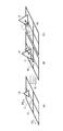
図1は、ズームインと被写体との関係を示す図である。図1(A)は、ズームイン前の被写体11、12とスクリーン13との関係を示す。図1(A)では、被写体11がスクリーン13面上に存在し、被写体12は、スクリーン13より奥に存在するとする。図1(A)に示すFO方向は、被写体が前に飛び出る方向であり、BA方向は、被写体が後ろに引き込まれる方向である。図1(A)に示す立体映像に対し、ズームインを行う。
図1(B)は、立体映像に期待する結果を示す。図1(B)に示すように、被写体11がスクリーン13よりも前に移動して見えることが望ましい。この場合、測距ユニットを用いる装置では測定距離が近距離に制限され、被写体との距離によっては視差量を調節する機構が作用しない場合がある。また、測距ユニットを設けるため、従来の装置はコスト増であった。
また、図1(C)は、従来技術の結果を示す。図1(C)では、輻輳点が被写体に合うように調節されるため、中央付近の被写体11が常にスクリーン13面上に見えるように視差量が調節される。
この方式では、スクリーン13面よりも後ろにある被写体12がさらに後ろに移動して不自然に見えるだけでなく、ズームで増大した視差量によっては両目が外に開いてしまう危険な映像となる場合がある。
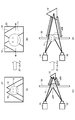
図2は、危険な映像を説明するための図である。図2(A)は、t-1フレームの映像例を示す。左目で左の被写体12を見て、右目で右の被写体12を見ているとする。これにより、被写体12は、被写体11よりも奥に見える。
図2(B)は、図2(A)に示す状態から従来方式で映像をズームインしたときのtフレームの映像例である。図2(B)に示すように、左目で見る左の被写体12は左にシフトし、右目で見る右の被写体12は、右にシフトする。なお、被写体11の視差量が0に調節される。
これにより、従来方式の映像は、左目は左に移動し、右目は右に移動し、両目が開いてしまう危険な映像になる。危険な映像となる理由は、人間の目は寄る方向には動くが、開く方向には動かないからである。
前述したように危険な映像となることを、左カメラ31と右カメラ32とを略平行に並べる撮像系で説明する。左カメラ31では、左目用の映像を撮影し、右カメラ32では、右目用の映像を撮影する。
図2(C)は、t-1フレーム時の視差の関係を示す。図2(C)では、輻輳点p34で被写体11が仮想スクリーン33に存在する。このとき、被写体12の視差量をd35とする。
図2(D)は、tフレーム時の視差の関係を示す。図2(D)では、被写体11が仮想スクリーン33面上に存在し続け、背景の被写体12はズームインに伴い、後ろに移動する。このときの視差量をd36とする。ここで、d35<d36の関係が成り立つ。
この結果、従来方式の映像は、ズームイン時に視差量が増大し、両目が外に開く映像となる危険性がある。したがって、従来技術では、ズーム時に視差量を適切に調節できず、立体映像の品質が良くないという問題点があった。
そこで、開示の技術は、上記問題点に鑑みてなされたものであり、ズーム時に視差量を適切に調節し、自然な立体映像を生成することができる画像処理装置、画像処理方法及び画像処理プログラムを提供することを目的とする。
開示の一態様の画像処理装置は、立体映像を処理する画像処理装置であって、
拡大又は縮小された立体映像から拡縮率を検出する拡縮率検出部と、撮影時における複数のカメラの間隔と、前記複数のカメラから輻輳点までの距離と、前記輻輳点での視差量とに基づく相似関係を用いて、前記間隔と前記拡縮率とにより表される前記視差量を算出する視差量算出部と、前記視差量算出部により算出された視差量を用いて前記立体映像の視差量を調節する視差量調節部とを備える。
拡大又は縮小された立体映像から拡縮率を検出する拡縮率検出部と、撮影時における複数のカメラの間隔と、前記複数のカメラから輻輳点までの距離と、前記輻輳点での視差量とに基づく相似関係を用いて、前記間隔と前記拡縮率とにより表される前記視差量を算出する視差量算出部と、前記視差量算出部により算出された視差量を用いて前記立体映像の視差量を調節する視差量調節部とを備える。
開示の技術によれば、ズーム時に視差量を適切に調節し、自然な立体映像を生成することができる。
100、200、300 画像処理装置
101、302 拡縮率検出部
102、201、303 視差量算出部
103、203、304 視差量調節部
121 乗算部
122 記憶部
131 記憶部
132 シフト制限部
133 シフト部
202 視差量補正部
301 光軸ズレ補正部
101、302 拡縮率検出部
102、201、303 視差量算出部
103、203、304 視差量調節部
121 乗算部
122 記憶部
131 記憶部
132 シフト制限部
133 シフト部
202 視差量補正部
301 光軸ズレ補正部
以下、図面に基づいて、実施例について説明する。
[実施例1]
<構成>
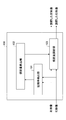
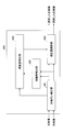
図3は、実施例1における画像処理装置100の構成の一例を示すブロック図である。図3に示す画像処理装置100は、拡縮率検出部101、視差量算出部102、視差量調節部103を備える。
<構成>
図3は、実施例1における画像処理装置100の構成の一例を示すブロック図である。図3に示す画像処理装置100は、拡縮率検出部101、視差量算出部102、視差量調節部103を備える。
画像処理装置100は、左映像、右映像を入力し、拡縮率検出部101、視差量調節部103に左右の映像を入力する。左映像、右映像については、画像処理装置100内部に記憶されていてもよいし、複数の撮像系からそれぞれ入力されてもよい。
拡縮率検出部101は、左右の映像が入力され、この左右の映像に基づいて、ズームイン(拡大)又はズームアウト(縮小)時の拡縮率を検出する。検出した拡縮率は、視差量算出部102に出力される。
拡縮率の検出方法は、公知の技術のいずれかを用いればよい。例えば、特開2005-332120を参照されたい。特開2005-332120号公報では、水平、垂直の両エッジピークコードの各ピークコードの位置間隔に対する時間変化比を拡縮率とする。
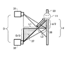
また、拡縮率検出部101は、例えば、次のように拡縮率を検出してもよい。図4は、拡縮率αの算出例を説明するための図である。図4に示す左カメラ31と右カメラ32とで被写体11を撮影する。このとき、ズームインを行って被写体11の位置が、カメラ31,32から輻輳点までの距離L1からカメラ方向にL2移動したとする。
このときの拡縮率αは、次の式により求められる。

よって、拡縮率αは、次のように変形される。
α=X/X’=L1/(L1-L2) ・・・式(2)
図3に戻り、視差量算出部102は、カメラ間隔Dと拡縮率αとを用いて、ズーム時の適切な視差量dを算出する。視差量算出部102については、図5を用いて説明する。
α=X/X’=L1/(L1-L2) ・・・式(2)
図3に戻り、視差量算出部102は、カメラ間隔Dと拡縮率αとを用いて、ズーム時の適切な視差量dを算出する。視差量算出部102については、図5を用いて説明する。
図5は、視差量算出部102の構成の一例を示すブロック図である。図5に示す視差量算出部102は、乗算部121、記憶部122を備える。記憶部122は、左カメラと右カメラとの間隔Dを記憶する。記憶部122は、この間隔Dを予め記憶しておくか、画像処理時に画像処理装置100に入力されて記憶しておく。
乗算部121は、視差量dを次の式により算出する。
d=(α-1)×D ・・・式(3)
式(3)に示すように、視差量dは、拡縮率αとカメラ間隔Dとで表される。式(3)で視差量が算出できる理由を以下に説明する。
d=(α-1)×D ・・・式(3)
式(3)に示すように、視差量dは、拡縮率αとカメラ間隔Dとで表される。式(3)で視差量が算出できる理由を以下に説明する。
図6は、拡縮率αと視差量dとカメラ間隔Dとの関係を示す図である。図6に示すように、被写体11を仮想スクリーン33上に投影したとすると、左右の映像で被写体11には視差量dが発生する。このとき、図6に示すように、三角形37と三角形38とが相似の関係にあることを用いると次の関係が成り立つ。
D/2:d/2=L1-L2:L2 ・・・式(4)
この式(4)を変形すると、次の式(5)が成り立つ。
d=L2/(L1-L2)×D ・・・式(5)
さらに、式(5)を変形し、式(6)とする。
d=((L1/(L1-L2))-1)×D ・・・式(6)
ここで、式(2)によりL1/(L1-L2)にαを代入すると、前述した式(3)が成り立つ。
d=(α―1)×D
よって、ズーム時の適切な視差量dは、拡縮率αとカメラ間隔Dとで算出することができる。求めた視差量dは、視差量調節部103に出力される。
D/2:d/2=L1-L2:L2 ・・・式(4)
この式(4)を変形すると、次の式(5)が成り立つ。
d=L2/(L1-L2)×D ・・・式(5)
さらに、式(5)を変形し、式(6)とする。
d=((L1/(L1-L2))-1)×D ・・・式(6)
ここで、式(2)によりL1/(L1-L2)にαを代入すると、前述した式(3)が成り立つ。
d=(α―1)×D
よって、ズーム時の適切な視差量dは、拡縮率αとカメラ間隔Dとで算出することができる。求めた視差量dは、視差量調節部103に出力される。
図3に戻り、視差量調節部103は、視差量算出部102から視差量dを取得する。視差量調節部103は、視差量dを取得すると、左右の映像の視差量がdとなるように調節する。視差量調節部103は、例えば、左の映像を左に視差量dの半分(d/2)シフトし、右の映像を右に視差量dの半分(d/2)シフトする。これにより、被写体は左右の映像で視差量dを有することになる。これにより、ズーム時に適切な視差量で左右の映像を調節することで、自然な立体映像を生成することができる。
図7は、ズーム時の自然な映像を説明するための図である。図7(A)に示すように、被写体11に対し、算出された視差量d40を有するよう立体映像をシフトさせる。これにより、図7(B)に示すように被写体11が前に移動するとともに、従来技術の結果(図2)において後ろに移動していた背景の被写体12も前に移動し、両目が開かない効果がある。
また、視差量調節部103は、ズームイン時に、スクリーン面からの被写体の飛び出し量を、輻輳角を用いて制限してもよい。図8は、視差量調節部103の構成の一例を示すブロック図である。
図8に示す視差量調節部103は、記憶部131、シフト制限部132、シフト部133を備える。記憶部131は、例えば、右カメラと左カメラとのカメラ間隔Dを記憶する。
シフト制限部132は、ズームイン時にスクリーン面からの被写体の飛び出し量を、輻輳角を用いて制限する。このとき、輻輳角θは、拡縮率αの変形式(7)により算出されるL2とカメラ間隔Dとを用いて、次の式(8)により算出される。
L2/L1=(α―1)/α ・・・式(7)
θ=2tan-1(D/(2×L2)) ・・・式(8)
なお、L1は、カメラの角度などのカメラパラメータにより事前に算出されておいてもよく、事前に設定されておいてもよい。
L2/L1=(α―1)/α ・・・式(7)
θ=2tan-1(D/(2×L2)) ・・・式(8)
なお、L1は、カメラの角度などのカメラパラメータにより事前に算出されておいてもよく、事前に設定されておいてもよい。
シフト制限部132は、算出した輻輳角θが一定の値以上になった場合、それ以上前に被写体を移動させないようにするため、左右の映像のシフトを行わない。よて、シフト制限部132は、輻輳角θが所定値未満のときに視差量dをシフト部133に出力し、輻輳角θが所定値以上の場合に視差量dをシフト部133に出力しない。所定値は、例えば、1度とする。この1度は、3Dコンソーシアムの3DC安全ガイドラインに基づく値である。
シフト部133は、シフト制限部132から取得した視差量dを用いて、左右の映像を水平方向にシフトする。シフトする量は、それぞれの映像に対してd/2である。
<動作>
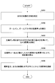
次に、実施例1における画像処理装置100の動作について説明する。図9は、実施例1における画像処理の一例を示すフローチャートである。
次に、実施例1における画像処理装置100の動作について説明する。図9は、実施例1における画像処理の一例を示すフローチャートである。
図9に示すステップS101で、拡縮率検出部101は、ズームイン(拡大)、ズームアウト(縮小)時の映像から拡縮率αを検出する。拡縮率αは、公知の求め方を用いればよい。
ステップS102で、視差量算出部102は、拡縮率α-1とカメラ間隔Dとを乗算することにより視差量dを算出する。
ステップS103で、視差量調節部103は、例えば、視差量dの半分ずつ、左右の映像を水平方向にシフトし、視差量を調節する。これにより、ズーム時に適切な視差量で映像をシフトすることができ、自然な立体映像を生成することができる。
図10は、視差量調節部103のシフト制限処理の一例を示すフローチャートである。図10に示す処理は、図9に示すステップS103で行われてもよい。
ステップS201で、シフト制限部132は、拡縮率αの式から算出されるL2とカメラ間隔Dとを用いて式(8)により、輻輳角θを算出する。
ステップS202で、シフト制限部132は、算出した輻輳角θが所定値以上であるか否かを判定する。輻輳角θが所定値以上であれば(ステップS102-YES)、この処理を終了し、輻輳角θが所定値未満であれば(ステップS102-NO)ステップS203に進む。
ステップS203で、シフト部133は、視差量分、左右の映像のいずれか、又は両方の映像を合計視差量分、水平方向にシフトして視差量を調節する。これにより、輻輳角が所定値以上の場合、ステップS203の処理を行わないことで、被写体が必要以上に飛び出すことを制限することができる。
以上、実施例1によれば、シフトする視差量を拡縮率から算出することで、例えば、ズームイン時に被写体が前方に定位する自然な立体映像の生成を可能とする。
(撮像系における無限遠点の視差量)
ここで、実施例1において撮像系における無限遠点の視差量が変化しないことを保証する。
ここで、実施例1において撮像系における無限遠点の視差量が変化しないことを保証する。
図11は、無限遠点の視差量が変化しないことを説明するための図である。図11に示すように、無限遠点の視差量は、左カメラ31と右カメラ32のカメラ間隔Dと同じであり、α倍ズームインするとαDとなる。
このままでは両目が開いてしまうことになるが、実施例1における処理を適用することで、α倍にズームインした時の視差量dは、(α―1)Dであるため、次の式が成り立つ。
αD-(α-1)D=D ・・・式(9)
この式(9)は、ズームイン時において、無限遠点の視差量が変化しないことが保証できることを示している。よって、実施例1では、無限遠点でも視差量が変化せずに、自然な立体映像を生成することができる。
αD-(α-1)D=D ・・・式(9)
この式(9)は、ズームイン時において、無限遠点の視差量が変化しないことが保証できることを示している。よって、実施例1では、無限遠点でも視差量が変化せずに、自然な立体映像を生成することができる。
なお、ズームアウトした時の視差量の調節処理は、ズームインした時の視差量の調節処理と同様にして行えばよい。
[実施例2]
次に、実施例2における画像処理装置200について説明する。実施例2では、実際のスクリーン幅に合わせて視差量を補正する。実際のスクリーン幅とは、映像が表示される画面の幅である。
次に、実施例2における画像処理装置200について説明する。実施例2では、実際のスクリーン幅に合わせて視差量を補正する。実際のスクリーン幅とは、映像が表示される画面の幅である。
<構成>
図12は、実施例2における画像処理装置200の構成の一例を示すブロック図である。図12に示す画像処理装置200は、拡縮率検出部101、視差量算出部201、視差量補正部202、視差量調節部203を備える。拡縮率検出部101は、実施例1と同様の機能を有するので、説明を省略する。
図12は、実施例2における画像処理装置200の構成の一例を示すブロック図である。図12に示す画像処理装置200は、拡縮率検出部101、視差量算出部201、視差量補正部202、視差量調節部203を備える。拡縮率検出部101は、実施例1と同様の機能を有するので、説明を省略する。
視差量算出部201は、実施例1同様にして算出した視差量dを視差量補正部202に出力する。
視差量補正部202は、取得した視差量dに対し、実際のスクリーン面の幅に合わせて視差量を補正する。このとき、補正後の視差量をd1とする。視差量補正部202は、仮想スクリーン面と実際のスクリーン面とが相似の関係にあることを用いて視差量d1を求める。
図13は、仮想スクリーン51面と実際のスクリーン52面との関係を示す図である。図13に示すように、仮想スクリーン51面と実際のスクリーン52面とは相似の関係が成り立つ。
よって、仮想スクリーン51の幅をW2、視差量をdとし、実際のスクリーン52の幅をW1、補正された視差量をd1とする。次の式(10)が成り立つ。
d:d1=W2:W1 ・・・式(10)
式(10)を変形すると、d1は式(11)により算出される。
d1=d×(W1/W2) ・・・式(11)
視差量補正部202は、式(11)により補正された視差量d1を算出する。算出した視差量d1は、視差量調節部203に出力される。なお、仮想スクリーンの幅W2は、次の式(12)により算出される。
W2=2×tan(θ1/2)×L1 ・・・式(12)
θ1:撮像時のカメラにおける水平方向の画角
L1:撮影時のカメラから輻輳点までの距離
図12に戻り、視差量調節部203は、視差量補正部202から取得した視差量d1を用いて、実施例1と同様にして左右の映像の視差量を調節する。
d:d1=W2:W1 ・・・式(10)
式(10)を変形すると、d1は式(11)により算出される。
d1=d×(W1/W2) ・・・式(11)
視差量補正部202は、式(11)により補正された視差量d1を算出する。算出した視差量d1は、視差量調節部203に出力される。なお、仮想スクリーンの幅W2は、次の式(12)により算出される。
W2=2×tan(θ1/2)×L1 ・・・式(12)
θ1:撮像時のカメラにおける水平方向の画角
L1:撮影時のカメラから輻輳点までの距離
図12に戻り、視差量調節部203は、視差量補正部202から取得した視差量d1を用いて、実施例1と同様にして左右の映像の視差量を調節する。
(視聴距離)
次に、実際のスクリーンにおける視聴距離について説明する。図14は、実際のスクリーンにおける視聴距離の一例を示す図である。図14に示すように、距離L3を、実施のスクリーンから目までの距離とする。
次に、実際のスクリーンにおける視聴距離について説明する。図14は、実際のスクリーンにおける視聴距離の一例を示す図である。図14に示すように、距離L3を、実施のスクリーンから目までの距離とする。
このとき視聴距離L3は、以下の式(13)により算出される。
L3=(1/2)×W1/tan(θ2/2) ・・・式(13)
W1:実際のスクリーン面の幅
θ2:水平方向の基準画角
水平方向の基準画角は、目の視聴できる角度によって決まる。
L3=(1/2)×W1/tan(θ2/2) ・・・式(13)
W1:実際のスクリーン面の幅
θ2:水平方向の基準画角
水平方向の基準画角は、目の視聴できる角度によって決まる。
(補正後の視差量)
次に、補正後の視差量d1の一例を示す。図15は、視差量d1の一例を示す図である。図15に示す例は、次のパラメータが設定されている。
θ1=39.6度(35mmフルサイズデジタル一眼レフカメラで、焦点距離は50mm)
W1=819mm(37型ディスプレイ)
L1=10000mm(輻輳点をカメラから10mの位置に設定)
D=65mm(一般的な人間の目の幅)
視差量補正部202は、式(3)、式(11)、式(12)を用いて拡縮率αを変動させると、図15に示す補正後の視差量d1を算出できる。例えば、拡縮率αが2のときは、補正後の視差量d1は、7.39mmであり、拡縮率αが3のときは、補正後の視差量d1は、14.78mmである。視差量補正部202は、ズーム時の拡縮率αに応じて算出した補正後の視差量d1を視差量調節部203に出力する。
次に、補正後の視差量d1の一例を示す。図15は、視差量d1の一例を示す図である。図15に示す例は、次のパラメータが設定されている。
θ1=39.6度(35mmフルサイズデジタル一眼レフカメラで、焦点距離は50mm)
W1=819mm(37型ディスプレイ)
L1=10000mm(輻輳点をカメラから10mの位置に設定)
D=65mm(一般的な人間の目の幅)
視差量補正部202は、式(3)、式(11)、式(12)を用いて拡縮率αを変動させると、図15に示す補正後の視差量d1を算出できる。例えば、拡縮率αが2のときは、補正後の視差量d1は、7.39mmであり、拡縮率αが3のときは、補正後の視差量d1は、14.78mmである。視差量補正部202は、ズーム時の拡縮率αに応じて算出した補正後の視差量d1を視差量調節部203に出力する。
(被写体の動き)
次に、図15で説明したパラメータを用いて、スクリーン(ディスプレイ)の大きさの違いによる被写体の動きについて説明する。
次に、図15で説明したパラメータを用いて、スクリーン(ディスプレイ)の大きさの違いによる被写体の動きについて説明する。
図16は、10000mmのディスプレイ、拡縮率2倍の被写体の動きを示す図である。図16に示すように、拡縮率α=2、W1=10000、水平の基準画角=39.6度とするとき、視聴距離は、式(13)により、13.9mが望ましい。
例えば、拡縮率αを2にしたとき、各被写体は、図16に示す位置に見える。例えば、被写体11は、実際のスクリーン面から飛び出す方向の1.8mの位置に見え、被写体12は、実際のスクリーン面から奥行き方向の2.2mの位置に見える。
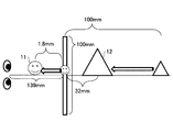
図17は、100mmのディスプレイ、拡縮率2倍の被写体の動きを示す図である。図17に示すように、拡縮率α=2、W1=100、水平の基準画角=39.6度とするとき、視聴距離は、式(13)により、139mmが望ましい。
例えば、拡縮率αを2にしたとき、各被写体は、図17に示す位置に見える。例えば、被写体11は、実際のスクリーン面から飛び出す方向の1.8mmの位置に見え、被写体12は、実際のスクリーン面から奥行き方向の32mmの位置に見える。
これにより、実際のスクリーンの幅に合わせて視差量を調節することで、実際のスクリーン幅に応じて自然な立体映像を生成することができる。
<動作>
次に、実施例2における画像処理装置200の動作について説明する。図18は、実施例2における画像処理の一例を示すフローチャートである。
次に、実施例2における画像処理装置200の動作について説明する。図18は、実施例2における画像処理の一例を示すフローチャートである。
図18に示すステップS301で、拡縮率検出部101は、ズームイン(拡大)、ズームアウト(縮小)時の映像から拡縮率αを検出する。拡縮率αは、公知の求め方を用いればよい。
ステップS302で、視差量算出部201は、拡縮率α-1とカメラ間隔Dとを乗算することにより視差量dを算出する。
ステップS303で、視差量補正部202は、視差量dを、実際のスクリーン幅に合わせて補正し、補正後の視差量d1を算出する。補正後の視差量d1は、式(11)により算出される。
ステップS304で、視差量調節部203は、補正後の視差量dの半分ずつ、左右の映像を水平方向にシフトし、視差量を調節する。これにより、実際のスクリーンの幅に合わせた適切な視差量で映像をシフトすることができ、自然な立体映像を生成することができる。
(表示系の無限遠点の視差量)
ここで、実施例2において表示系における無限遠点の視差量が変化しないことを保証する。
ここで、実施例2において表示系における無限遠点の視差量が変化しないことを保証する。
図8で説明した通り、撮像系における無限遠点の視差量はDであることから、表示系における無限遠点の視差量d2は、次の式(14)により算出される。
d2=D×(W1/W2) ・・・式(14)
D:カメラ間隔
W1:実際のスクリーン面の幅
W2:仮想スクリーン面の幅
また、視聴距離を考慮に入れた無限遠点の視差量d3は、次の式(15)により算出される。
d3=d2×(L4/L3) ・・・式(15)
L3:実際のスクリーンを見る際の視聴距離
L4:仮想スクリーンを見る際の視聴距離
L4=(1/2)×W2/tan(θ2/2) ・・・式(16)
L3=(1/2)×W1/tan(θ2/2) ・・・式(13)
ここで、式(13)と式(14)と式(16)とを式(15)に代入すると、d3=Dとなり、表示系における無限遠点の視差量が変化しないことが保証されたことを示す。
d2=D×(W1/W2) ・・・式(14)
D:カメラ間隔
W1:実際のスクリーン面の幅
W2:仮想スクリーン面の幅
また、視聴距離を考慮に入れた無限遠点の視差量d3は、次の式(15)により算出される。
d3=d2×(L4/L3) ・・・式(15)
L3:実際のスクリーンを見る際の視聴距離
L4:仮想スクリーンを見る際の視聴距離
L4=(1/2)×W2/tan(θ2/2) ・・・式(16)
L3=(1/2)×W1/tan(θ2/2) ・・・式(13)
ここで、式(13)と式(14)と式(16)とを式(15)に代入すると、d3=Dとなり、表示系における無限遠点の視差量が変化しないことが保証されたことを示す。
なお、撮影時のカメラ間隔Dが目の幅以上の場合、目が外に開く可能性がある。よって、この値Dを眼間距離D’に補正することが望ましい。例えば、表示系では、(-D+D’)/β(β=L4/L3(仮想スクリーンを見る際の視聴距離/実際のスクリーンを見る際の視聴距離))分、視差量調節部203が左右の映像をシフトすればよい。眼間距離D’は、例えば、一般的な人間の目の幅である65mmに設定しておけばよい。
以上、実施例2によれば、シフトする視差量を拡縮率及び実際のスクリーン幅に基づき算出することで、例えば、ズームイン時に被写体が前方に定位する自然な立体映像の生成を可能とする。
なお、ズームアウトした時の視差量の調節処理は、ズームインした時の視差量の調節処理と同様にして行えばよい。
[実施例3]
次に、実施例3における画像処理装置300について説明する。実施例3では、光軸のずれを補正して、補正量をカメラ間隔に反映する。
次に、実施例3における画像処理装置300について説明する。実施例3では、光軸のずれを補正して、補正量をカメラ間隔に反映する。
<構成>
図19は、実施例3における画像処理装置300の構成の一例を示すブロック図である。図19に示す画像処理装置300は、光軸ズレ補正部301、拡縮率検出部302、視差量算出部303、視差量調節部304を備える。
図19は、実施例3における画像処理装置300の構成の一例を示すブロック図である。図19に示す画像処理装置300は、光軸ズレ補正部301、拡縮率検出部302、視差量算出部303、視差量調節部304を備える。
図19に示す光軸ズレ補正部301は、レンズと撮像素子との間の光軸のズレ量を計測し、このズレ量を用いて左右の映像を補正する。光軸ズレ補正については、公知の技術を用いればよい。光軸ズレ補正部301は、実際のスクリーン面における水平方向の補正量d4を視差量算出部303に出力する。
視差量算出部303は、補正量d4を用いてカメラ間隔Dを修正する。補正量算出部303は、例えば、次の式(17)を用いてカメラ間隔Dを修正する。修正後のカメラ間隔をD1とする。
D1=D+d4×(W2/W1) ・・・式(17)
視差量算出部303は、修正後のカメラ間隔D1と拡縮率αとを用いて視差量d5を式(18)により算出する。
d5=(α-1)×D1 ・・・式(18)
算出された視差量d5は、視差量調節部304に出力される。
D1=D+d4×(W2/W1) ・・・式(17)
視差量算出部303は、修正後のカメラ間隔D1と拡縮率αとを用いて視差量d5を式(18)により算出する。
d5=(α-1)×D1 ・・・式(18)
算出された視差量d5は、視差量調節部304に出力される。
視差量調節部304は、視差量d5を用いて、光軸ズレ補正後の左右の映像を補正する。補正処理は、実施例1で説明した処理と同様である。
<動作>
次に、実施例3における画像処理装置300の動作について説明する。図20は、実施例3における画像処理の一例を示すフローチャートである。
次に、実施例3における画像処理装置300の動作について説明する。図20は、実施例3における画像処理の一例を示すフローチャートである。
図20に示すステップS401で、光軸ズレ補正部301は、公知の技術を用いて左右の映像の光軸のズレを補正する。水平方向の補正量を視差量算出部303に出力する。
ステップS402で、拡縮率検出部302は、ズームイン(拡大)、ズームアウト(縮小)時の光軸ズレ補正後の映像から拡縮率αを検出する。拡縮率αは、公知の求め方を用いればよい。
ステップS403で、視差量算出部303は、光軸ズレ補正部301により補正した水平方向のd4を用いてカメラ間隔Dを式(17)により修正する。
ステップS404で、視差量算出部303は、拡縮率α-1と修正後のカメラ間隔D1とを乗算することにより視差量d5を算出する。
ステップS405で、視差量調節部304は、例えば、視差量d5の半分ずつ、左右の映像を水平方向にシフトし、視差量を調節する。これにより、光軸ズレを補正していても、ズーム時に適切な視差量で映像をシフトすることができ、自然な立体映像を生成することができる。なお、実施例3においても、実施例2における実際のスクリーン幅に合わせて視差量を補正するようにしてもよい。また、実施例3でも、実施例1における輻輳角によるシフト制限を行ってもよい。
以上、実施例3によれば、シフトする視差量を拡縮率及び光軸ズレ補正後のカメラ間隔に基づき算出することで、例えば、ズームイン時に被写体が前方に定位する自然な立体映像の生成を可能とする。
なお、ズームアウトした時の視差量の調節処理は、ズームインした時の視差量の調節処理と同様にして行えばよい。
[変形例]
図21は、変形例における画像処理装置400の構成の一例を示すブロック図である。図21に示すように、画像処理装置400は、制御部401、主記憶部402、補助記憶部403、ドライブ装置404、入力部406、表示部407、撮像部408、409を備える。これら各構成は、バスを介して相互にデータ送受信可能に接続されている。
図21は、変形例における画像処理装置400の構成の一例を示すブロック図である。図21に示すように、画像処理装置400は、制御部401、主記憶部402、補助記憶部403、ドライブ装置404、入力部406、表示部407、撮像部408、409を備える。これら各構成は、バスを介して相互にデータ送受信可能に接続されている。
制御部401は、コンピュータの中で、各装置の制御やデータの演算、加工を行うCPUである。また、制御部401は、主記憶部402や補助記憶部403に記憶されたプログラムを実行する演算装置であり、入力部406や記憶装置からデータを受け取り、演算、加工した上で、表示部407や記憶装置などに出力する。
また、制御部401は、補助記憶部403などに記憶されている画像処理プログラムを実行し、実施例において説明した画像処理を行う。
主記憶部402は、ROM(Read Only Memory)やRAM(Random Access Memory)などであり、制御部401が実行する基本ソフトウェアであるOS(Operating System)やアプリケーションソフトウェアなどのプログラムやデータを記憶又は一時保存する記憶装置である。
補助記憶部403は、HDD(Hard Disk Drive)などであり、アプリケーションソフトウェアなどに関連するデータを記憶する記憶装置である。
ドライブ装置404は、記録媒体405、例えばフレキシブルディスクからプログラムを読み出し、記憶装置にインストールする。
また、記録媒体405に、所定のプログラムを格納し、この記録媒体405に格納されたプログラムはドライブ装置404を介して画像処理装置400にインストールされる。インストールされた所定のプログラムは、画像処理装置400により実行可能となる。
入力部406は、カーソルキー、数字入力及び各種機能キー等を備えたキーボード、表示部407の表示画面上でキーの選択等を行うためのマウスやスライスパット等を有する。また、入力部406は、ユーザが制御部401に操作指示を与えたり、データを入力したりするためのユーザインターフェースである。
表示部407は、例えばLCD(Liquid Crystal Display)等であり、制御部401から入力される表示データに応じた表示が行われる。なお、表示部407は、外部に設けられてもよく、その場合は、画像処理装置400は、表示制御部を有する。
撮像部408は、例えばCCD(Charge Coupled Device)を有し、例えば左目用の撮像画像を生成する。
撮像部409は、例えばCCD(Charge Coupled Device)を有し、例えば右目用の撮像画像を生成する。撮像部408、409により撮像された画像を含む映像は、制御部401により、各実施例で説明した処理で視差量を調節される。
画像処理装置400は、例えば複数のカメラを有する撮影装置、携帯端末装置などである。また、画像処理装置400は、撮像部408、409を別装置とし、別装置から左右の映像を取得したり、内部に記憶しておいた左右の映像を取得したりする場合は情報処理装置にも適用可能である。
前述した各実施例で説明した各部は、例えば、制御部401により実現されうる。また、各実施例における画像処理装置を1又は複数の半導体集積化回路として、携帯端末装置や撮影装置や情報処理装置などに実装することも可能である。
また、前述した実施例で説明した画像処理を実現するためのプログラムを記録媒体に記録することで、実施例での画像処理をコンピュータに実施させることができる。
また、このプログラムを記録媒体に記録し、このプログラムが記録された記録媒体をコンピュータや携帯端末装置に読み取らせて、前述した制御処理を実現させることも可能である。なお、記録媒体は、CD-ROM、フレキシブルディスク、光磁気ディスク等の様に情報を光学的,電気的或いは磁気的に記録する記録媒体、ROM、フラッシュメモリ等の様に情報を電気的に記録する半導体メモリ等、様々なタイプの記録媒体を用いることができる。
以上、実施例について詳述したが、特定の実施例に限定されるものではなく、特許請求の範囲に記載された範囲内において、種々の変形及び変更が可能である。また、前述した実施例の構成要素を全部又は複数を組み合わせることも可能である。
Claims (6)
- 立体映像を処理する画像処理装置であって、
拡大又は縮小された立体映像から拡縮率を検出する拡縮率検出部と、
撮影時における複数のカメラの間隔と、前記複数のカメラから輻輳点までの距離と、前記輻輳点での視差量とに基づく相似関係を用いて、前記間隔と前記拡縮率とにより表される前記視差量を算出する視差量算出部と、
前記視差量算出部により算出された視差量を用いて前記立体映像の視差量を調節する視差量調節部と、
を備える画像処理装置。 - 前記視差量算出部により算出された視差量を、立体映像が表示されるスクリーンの幅に応じて補正する視差量補正部をさらに備え、
前記視差量調節部は、
補正された視差量を用いて前記立体映像の視差量を調節する請求項1記載の画像処理装置。 - 前記視差量調節部は、
前記視差量に基づく前記スクリーンからの被写体の飛び出し量を、輻輳角を用いて制限する制限部を備える請求項2記載の画像処理装置。 - 前記カメラの光軸のズレ量を計測し、光軸のズレを補正する光軸補正部をさらに備え、
前記視差量算出部は、
前記光軸補正部により計測された光軸のズレ量を用いて前記間隔を修正する請求項1乃至3いずれか一項に記載の画像処理装置。 - 立体映像を処理する画像処理装置に実行される画像処理方法であって、
拡大又は縮小された立体映像から拡縮率を検出し、
撮影時における複数のカメラの間隔と、前記複数のカメラから輻輳点までの距離と、前記輻輳点での視差量とに基づく相似関係を用いて、前記間隔と前記拡縮率とにより表される前記視差量を算出し、
算出された前記視差量を用いて前記立体映像の視差量を調節する画像処理方法。 - 拡大又は縮小された立体映像から拡縮率を検出し、
撮影時における複数のカメラの間隔と、前記複数のカメラから輻輳点までの距離と、前記輻輳点での視差量とに基づく相似関係を用いて、前記間隔と前記拡縮率とにより表される前記視差量を算出し、
前記視差量算出部により算出された視差量を用いて前記立体映像の視差量を調節する、
処理をコンピュータに実行させる画像処理プログラム。
Priority Applications (2)
| Application Number | Priority Date | Filing Date | Title |
|---|---|---|---|
| PCT/JP2011/058217 WO2012131979A1 (ja) | 2011-03-31 | 2011-03-31 | 画像処理装置、画像処理方法及び画像処理プログラム |
| JP2013506987A JP5725161B2 (ja) | 2011-03-31 | 2011-03-31 | 画像処理装置、画像処理方法及び画像処理プログラム |
Applications Claiming Priority (1)
| Application Number | Priority Date | Filing Date | Title |
|---|---|---|---|
| PCT/JP2011/058217 WO2012131979A1 (ja) | 2011-03-31 | 2011-03-31 | 画像処理装置、画像処理方法及び画像処理プログラム |
Publications (1)
| Publication Number | Publication Date |
|---|---|
| WO2012131979A1 true WO2012131979A1 (ja) | 2012-10-04 |
Family
ID=46929800
Family Applications (1)
| Application Number | Title | Priority Date | Filing Date |
|---|---|---|---|
| PCT/JP2011/058217 Ceased WO2012131979A1 (ja) | 2011-03-31 | 2011-03-31 | 画像処理装置、画像処理方法及び画像処理プログラム |
Country Status (2)
| Country | Link |
|---|---|
| JP (1) | JP5725161B2 (ja) |
| WO (1) | WO2012131979A1 (ja) |
Citations (3)
| Publication number | Priority date | Publication date | Assignee | Title |
|---|---|---|---|---|
| JPH0787385A (ja) * | 1993-09-10 | 1995-03-31 | Canon Inc | 撮像装置 |
| JPH089421A (ja) * | 1994-06-20 | 1996-01-12 | Sanyo Electric Co Ltd | 立体映像装置 |
| JP2006270924A (ja) * | 2005-02-28 | 2006-10-05 | Victor Co Of Japan Ltd | 映像データ処理装置、映像再生装置、映像データ処理方法、映像再生方法、これらの方法をコンピュータによって実行するためのプログラム並びに記録媒体 |
Family Cites Families (3)
| Publication number | Priority date | Publication date | Assignee | Title |
|---|---|---|---|---|
| JP3653790B2 (ja) * | 1995-05-23 | 2005-06-02 | 松下電器産業株式会社 | 立体電子ズーム装置及び立体画質制御装置 |
| JP2003052058A (ja) * | 2001-08-06 | 2003-02-21 | Nippon Hoso Kyokai <Nhk> | 立体画像撮像装置 |
| JP4407921B2 (ja) * | 2004-05-19 | 2010-02-03 | ダイハツ工業株式会社 | 障害物認識方法及び障害物認識装置 |
-
2011
- 2011-03-31 JP JP2013506987A patent/JP5725161B2/ja not_active Expired - Fee Related
- 2011-03-31 WO PCT/JP2011/058217 patent/WO2012131979A1/ja not_active Ceased
Patent Citations (3)
| Publication number | Priority date | Publication date | Assignee | Title |
|---|---|---|---|---|
| JPH0787385A (ja) * | 1993-09-10 | 1995-03-31 | Canon Inc | 撮像装置 |
| JPH089421A (ja) * | 1994-06-20 | 1996-01-12 | Sanyo Electric Co Ltd | 立体映像装置 |
| JP2006270924A (ja) * | 2005-02-28 | 2006-10-05 | Victor Co Of Japan Ltd | 映像データ処理装置、映像再生装置、映像データ処理方法、映像再生方法、これらの方法をコンピュータによって実行するためのプログラム並びに記録媒体 |
Also Published As
| Publication number | Publication date |
|---|---|
| JP5725161B2 (ja) | 2015-05-27 |
| JPWO2012131979A1 (ja) | 2014-07-24 |
Similar Documents
| Publication | Publication Date | Title |
|---|---|---|
| US9998650B2 (en) | Image processing apparatus and image pickup apparatus for adding blur in an image according to depth map | |
| CN102428707B (zh) | 立体视用图像对位装置和立体视用图像对位方法 | |
| US9019387B2 (en) | Imaging device and method of obtaining image | |
| EP2698766B1 (en) | Motion estimation device, depth estimation device, and motion estimation method | |
| TWI433530B (zh) | 具有立體影像攝影引導的攝影系統與方法及自動調整方法 | |
| JP4880096B1 (ja) | 多視点撮影制御装置、多視点撮影制御方法及び多視点撮影制御プログラム | |
| CN103843329B (zh) | 用于立体图像对的有条件显示的方法和设备 | |
| US20120224032A1 (en) | Image capturing device, image capturing device control method, and program | |
| US20130113793A1 (en) | Image processing device, image processing method, and image processing program | |
| CN102314043A (zh) | 人脸区块辅助对焦的方法 | |
| KR101897549B1 (ko) | 휴대 단말기에서 카메라 뷰 영역을 표시하는 장치 및 방법 | |
| CN104460011B (zh) | 立体成像装置和立体图像生成方法 | |
| US20120007819A1 (en) | Automatic Convergence Based on Touchscreen Input for Stereoscopic Imaging | |
| CN115633261A (zh) | 拍摄方法、拍摄装置、电子设备和计算机可读存储介质 | |
| US20160275657A1 (en) | Imaging apparatus, image processing apparatus and method of processing image | |
| JPWO2011129036A1 (ja) | 撮像装置および集積回路 | |
| JP5725161B2 (ja) | 画像処理装置、画像処理方法及び画像処理プログラム | |
| US9325975B2 (en) | Image display apparatus, parallax adjustment display method thereof, and image capturing apparatus | |
| WO2013069279A1 (ja) | 撮像装置 | |
| US20160065941A1 (en) | Three-dimensional image capturing apparatus and storage medium storing three-dimensional image capturing program | |
| JP5453552B2 (ja) | 撮影装置、方法及びプログラム | |
| JP5741353B2 (ja) | 画像処理システム、画像処理方法および画像処理プログラム | |
| TW201413368A (zh) | 依據物距值及兩眼間距值對焦之立體取像裝置及其方法、程式產品、紀錄媒體與取像對位方法 | |
| JP5221827B1 (ja) | 立体映像撮影装置及びズーム動作の制御方法 | |
| JP2012220603A (ja) | 3d映像信号撮影装置 |
Legal Events
| Date | Code | Title | Description |
|---|---|---|---|
| 121 | Ep: the epo has been informed by wipo that ep was designated in this application |
Ref document number: 11862344 Country of ref document: EP Kind code of ref document: A1 |
|
| ENP | Entry into the national phase |
Ref document number: 2013506987 Country of ref document: JP Kind code of ref document: A |
|
| NENP | Non-entry into the national phase |
Ref country code: DE |
|
| 122 | Ep: pct application non-entry in european phase |
Ref document number: 11862344 Country of ref document: EP Kind code of ref document: A1 |