WO2012131945A1 - 画像表示装置及びその取付位置調整方法 - Google Patents
画像表示装置及びその取付位置調整方法 Download PDFInfo
- Publication number
- WO2012131945A1 WO2012131945A1 PCT/JP2011/058056 JP2011058056W WO2012131945A1 WO 2012131945 A1 WO2012131945 A1 WO 2012131945A1 JP 2011058056 W JP2011058056 W JP 2011058056W WO 2012131945 A1 WO2012131945 A1 WO 2012131945A1
- Authority
- WO
- WIPO (PCT)
- Prior art keywords
- optical element
- adjustment
- observer
- light source
- image display
- Prior art date
- Legal status (The legal status is an assumption and is not a legal conclusion. Google has not performed a legal analysis and makes no representation as to the accuracy of the status listed.)
- Ceased
Links
Images




Classifications
-
- G—PHYSICS
- G02—OPTICS
- G02B—OPTICAL ELEMENTS, SYSTEMS OR APPARATUS
- G02B27/00—Optical systems or apparatus not provided for by any of the groups G02B1/00 - G02B26/00, G02B30/00
- G02B27/01—Head-up displays
-
- B—PERFORMING OPERATIONS; TRANSPORTING
- B60—VEHICLES IN GENERAL
- B60K—ARRANGEMENT OR MOUNTING OF PROPULSION UNITS OR OF TRANSMISSIONS IN VEHICLES; ARRANGEMENT OR MOUNTING OF PLURAL DIVERSE PRIME-MOVERS IN VEHICLES; AUXILIARY DRIVES FOR VEHICLES; INSTRUMENTATION OR DASHBOARDS FOR VEHICLES; ARRANGEMENTS IN CONNECTION WITH COOLING, AIR INTAKE, GAS EXHAUST OR FUEL SUPPLY OF PROPULSION UNITS IN VEHICLES
- B60K35/00—Instruments specially adapted for vehicles; Arrangement of instruments in or on vehicles
- B60K35/20—Output arrangements, i.e. from vehicle to user, associated with vehicle functions or specially adapted therefor
- B60K35/21—Output arrangements, i.e. from vehicle to user, associated with vehicle functions or specially adapted therefor using visual output, e.g. blinking lights or matrix displays
- B60K35/23—Head-up displays [HUD]
- B60K35/235—Head-up displays [HUD] with means for detecting the driver's gaze direction or eye points
-
- B—PERFORMING OPERATIONS; TRANSPORTING
- B60—VEHICLES IN GENERAL
- B60K—ARRANGEMENT OR MOUNTING OF PROPULSION UNITS OR OF TRANSMISSIONS IN VEHICLES; ARRANGEMENT OR MOUNTING OF PLURAL DIVERSE PRIME-MOVERS IN VEHICLES; AUXILIARY DRIVES FOR VEHICLES; INSTRUMENTATION OR DASHBOARDS FOR VEHICLES; ARRANGEMENTS IN CONNECTION WITH COOLING, AIR INTAKE, GAS EXHAUST OR FUEL SUPPLY OF PROPULSION UNITS IN VEHICLES
- B60K35/00—Instruments specially adapted for vehicles; Arrangement of instruments in or on vehicles
- B60K35/50—Instruments characterised by their means of attachment to or integration in the vehicle
-
- B—PERFORMING OPERATIONS; TRANSPORTING
- B60—VEHICLES IN GENERAL
- B60K—ARRANGEMENT OR MOUNTING OF PROPULSION UNITS OR OF TRANSMISSIONS IN VEHICLES; ARRANGEMENT OR MOUNTING OF PLURAL DIVERSE PRIME-MOVERS IN VEHICLES; AUXILIARY DRIVES FOR VEHICLES; INSTRUMENTATION OR DASHBOARDS FOR VEHICLES; ARRANGEMENTS IN CONNECTION WITH COOLING, AIR INTAKE, GAS EXHAUST OR FUEL SUPPLY OF PROPULSION UNITS IN VEHICLES
- B60K35/00—Instruments specially adapted for vehicles; Arrangement of instruments in or on vehicles
- B60K35/60—Instruments characterised by their location or relative disposition in or on vehicles
-
- B—PERFORMING OPERATIONS; TRANSPORTING
- B60—VEHICLES IN GENERAL
- B60K—ARRANGEMENT OR MOUNTING OF PROPULSION UNITS OR OF TRANSMISSIONS IN VEHICLES; ARRANGEMENT OR MOUNTING OF PLURAL DIVERSE PRIME-MOVERS IN VEHICLES; AUXILIARY DRIVES FOR VEHICLES; INSTRUMENTATION OR DASHBOARDS FOR VEHICLES; ARRANGEMENTS IN CONNECTION WITH COOLING, AIR INTAKE, GAS EXHAUST OR FUEL SUPPLY OF PROPULSION UNITS IN VEHICLES
- B60K2360/00—Indexing scheme associated with groups B60K35/00 or B60K37/00 relating to details of instruments or dashboards
- B60K2360/20—Optical features of instruments
- B60K2360/27—Optical features of instruments using semi-transparent optical elements
-
- B—PERFORMING OPERATIONS; TRANSPORTING
- B60—VEHICLES IN GENERAL
- B60K—ARRANGEMENT OR MOUNTING OF PROPULSION UNITS OR OF TRANSMISSIONS IN VEHICLES; ARRANGEMENT OR MOUNTING OF PLURAL DIVERSE PRIME-MOVERS IN VEHICLES; AUXILIARY DRIVES FOR VEHICLES; INSTRUMENTATION OR DASHBOARDS FOR VEHICLES; ARRANGEMENTS IN CONNECTION WITH COOLING, AIR INTAKE, GAS EXHAUST OR FUEL SUPPLY OF PROPULSION UNITS IN VEHICLES
- B60K2360/00—Indexing scheme associated with groups B60K35/00 or B60K37/00 relating to details of instruments or dashboards
- B60K2360/20—Optical features of instruments
- B60K2360/33—Illumination features
- B60K2360/334—Projection means
-
- B—PERFORMING OPERATIONS; TRANSPORTING
- B60—VEHICLES IN GENERAL
- B60K—ARRANGEMENT OR MOUNTING OF PROPULSION UNITS OR OF TRANSMISSIONS IN VEHICLES; ARRANGEMENT OR MOUNTING OF PLURAL DIVERSE PRIME-MOVERS IN VEHICLES; AUXILIARY DRIVES FOR VEHICLES; INSTRUMENTATION OR DASHBOARDS FOR VEHICLES; ARRANGEMENTS IN CONNECTION WITH COOLING, AIR INTAKE, GAS EXHAUST OR FUEL SUPPLY OF PROPULSION UNITS IN VEHICLES
- B60K2360/00—Indexing scheme associated with groups B60K35/00 or B60K37/00 relating to details of instruments or dashboards
- B60K2360/77—Instrument locations other than the dashboard
- B60K2360/771—Instrument locations other than the dashboard on the ceiling
-
- B—PERFORMING OPERATIONS; TRANSPORTING
- B60—VEHICLES IN GENERAL
- B60Y—INDEXING SCHEME RELATING TO ASPECTS CROSS-CUTTING VEHICLE TECHNOLOGY
- B60Y2304/00—Optimising design; Manufacturing; Testing
- B60Y2304/09—Testing or calibrating during manufacturing
-
- G—PHYSICS
- G02—OPTICS
- G02B—OPTICAL ELEMENTS, SYSTEMS OR APPARATUS
- G02B27/00—Optical systems or apparatus not provided for by any of the groups G02B1/00 - G02B26/00, G02B30/00
- G02B27/01—Head-up displays
- G02B27/0179—Display position adjusting means not related to the information to be displayed
- G02B2027/0181—Adaptation to the pilot/driver
Definitions
- the present invention relates to a head-up display installed on a moving body.
- Patent Document 1 discloses a head-up display that includes a display device and a combiner and is installed on a vehicle interior ceiling.
- the installation position of a display that has been installed in the vehicle has already been adjusted, and an image is appropriately displayed according to the seating position of the user. It is set to be visible.
- the user himself / herself has to adjust the attachment position so that the image can be seen appropriately. At that time, the user usually starts up the system and performs adjustment while viewing the displayed image.
- An object of the present invention is to provide an image display device capable of appropriately adjusting the mounting position without the need to start the system.
- the invention according to claim 1 is an image display device, which reflects the projection light from the light source and forms a virtual image that is visible from a predetermined position by an observer, the projection light, and the projection light
- the observation adjustment member is configured such that the appearance from the observer becomes a specific one in accordance with the adjustment by the adjustment mechanism of the observer.
- the invention according to claim 11 is a light source unit that accommodates a light source, an optical element that reflects a projection light from the light source and forms a virtual image that can be viewed from a predetermined position by an observer, and the projection light.
- An adjustment position adjustment method for an image display device comprising: an adjustment member, wherein the optical element is moved in a front-rear direction, which is a direction connecting the optical element and the light source unit, while visually recognizing the observation adjustment member. The position at which the observation adjustment member looks specific is determined as the position of the optical element.
- the invention according to claim 12 is a light source that projects light, an optical element that reflects the light from the light source, and forms a virtual image that can be viewed from a predetermined position by an observer, and the light source.
- An observation adjustment member whose angle changes, and the observation adjustment member has a cylindrical shape having a hole through which the line of sight of the observer at the predetermined position is transmitted, and is adjusted by the adjustment mechanism of the observer Accordingly, the appearance of the opposite side of the observer through the hole changes.
- FIG. 1 It is a figure which shows typically the state which installed the head up display which concerns on an Example in the vehicle interior. It is the perspective view which looked at the head-up display from diagonally upward. It is the top view which looked at the head up display from the upper part. It is a side view of a head up display. A method for adjusting the position of the head-up display in the left-right direction will be described. The position adjustment method of the front-back direction of a head-up display is shown. An example of the adjustment member and how it is seen from the user are shown. The other example of the member for adjustment and how it is seen from a user are shown.
- the image display device reflects the projection light from the light source and forms an optical element that is visible from a predetermined position by the observer, the projection light, and the projection light.
- the observation adjustment member is configured to have a specific appearance from the observer according to the adjustment by the adjustment mechanism of the observer.
- the image display device described above reflects light from the light source by an optical element, and displays a virtual image that is visible to an observer.
- the observer adjusts the positional relationship or the angular relationship between the projection light and the optical element by operating the adjustment mechanism.
- the position or angle of the observation adjustment member with respect to the line of sight of the observer toward the optical element changes according to the adjustment to the adjustment mechanism.
- the observation adjustment member is configured such that the appearance of the member from the observer becomes specific according to the adjustment of the adjustment mechanism. Therefore, the observer can attach the image display device to an appropriate position by operating the adjustment mechanism and adjusting the appearance of the observation adjustment member to be a specific one.
- the observation adjustment member is configured to transmit light in a direction along the projection light reflected by the optical element. Therefore, the optical element can be arranged at an appropriate position based on how it is viewed by the observer.
- the observation adjustment member is a pair of adjustment members having a hole having a predetermined length provided in a direction along the reflection direction of the projection light.
- the pair of adjusting members are attached to both ends in the length direction of the optical element holding member that holds the optical element. Thereby, the front-back direction position of an optical element can be adjusted correctly.
- the pair of adjustment members are arranged such that the distance between the end portions on the light source side is shorter than the distance between the end portions on the side opposite to the light source, with respect to the optical element.
- the light is transmitted at an angle such that the transmission direction of the light passing through the adjustment member intersects on the light source side. That is, since the adjustment member is directed toward the seated user, the user can correctly adjust the mounting position in the seated state.
- the pair of adjusting members are attached at an angle substantially perpendicular to the surface of the optical element.
- the projection light reflected by the optical element can be matched with the observer's line of sight.
- the optical element holding member holds the optical element rotatably with respect to a rotation axis extending in a length direction of the optical element, and the pair of adjustment elements The member is attached in the vicinity of the rotating shaft.
- an adjustment mark is provided at the center of the optical element.
- the observer can adjust the position of the optical element in the left-right direction using the adjustment mark.
- the observation adjustment member is a front-rear direction that is a direction connecting the optical element and the light source unit, and the front-rear direction. It is configured to be movable in the vertical direction, which is perpendicular to the longitudinal direction of the optical element and perpendicular to the length direction of the optical element. Thereby, the observer can determine an appropriate position of the optical element using the observation adjustment member, and can fix the optical element at the position.
- a light source unit that houses a light source, an optical element for reflecting a projection light from the light source, and forming a virtual image that can be viewed from a predetermined position by an observer, and the projection
- An adjustment mechanism for the observer to adjust the positional relationship or angular relationship between light and the optical element, and the position or angle of the observer with respect to the line of sight to the optical element changes according to the adjustment by the adjustment mechanism
- An observation position adjustment method for an image display device comprising: an observation adjustment member that moves the optical element in a front-rear direction that is a direction connecting the optical element and the light source unit while visually recognizing the observation adjustment member. Then, the position where the appearance of the observation adjustment member is specific is determined as the position of the optical element.
- the position or angle of the observation adjustment member with respect to the line of sight to the optical element of the observer changes according to the adjustment to the adjustment mechanism.
- the observation adjustment member is configured such that the appearance of the member from the observer becomes specific according to the adjustment of the adjustment mechanism. Therefore, the observer can attach the image display device to an appropriate position by operating the adjustment mechanism and adjusting the appearance of the observation adjustment member to be a specific one.
- the image display device includes a light source that projects light, and an optical that reflects the light from the light source and forms a virtual image that can be viewed from a predetermined position by an observer.
- An observation adjustment member whose position or angle with respect to the line of sight to the element changes, and the observation adjustment member has a cylindrical shape having a hole through which the line of sight of the observer at the predetermined position is transmitted. According to the adjustment by the adjustment mechanism, the appearance of the opposite side through the hole by the observer changes. Therefore, the observer can attach the image display device to an appropriate position by adjusting the appearance by operating the adjustment mechanism.
- the observation adjustment member is attached to both ends of the optical element in the left-right direction for the observer.
- FIG. 1 schematically shows a state in which the head-up display according to the embodiment is installed in the vehicle interior of the vehicle.
- FIG. 1 is a side view of the driver's seat of the vehicle 1, and a driver (also referred to as “user”) 7 is seated on a seat 5 in the passenger compartment.
- a windshield 4 of the vehicle 1 is located in front of the driver 7.
- the head-up display 10 is installed diagonally upward in front of the driver 7. Although details will be described later, the head-up display 10 includes a light source unit 11 and a combiner 20. As indicated by the broken line, the light emitted from the light source unit 11 is reflected by the combiner 20 and reaches the eyes of the driver 7. Accordingly, the driver 7 visually recognizes the virtual image 30 at a position in front of the vehicle. Note that the tip of the arrow of the virtual image 30 indicates the upward direction.
- FIG. 2 is a perspective view of the head-up display 10 as viewed obliquely from above.
- FIG. 3 is a plan view of the head-up display 10 as viewed from above, and
- FIG. 4 is a side view of the head-up display 10.
- the “front-rear direction” refers to the X direction shown in FIG. 2, that is, the direction connecting the light source unit 11 and the combiner 20.
- the “left-right direction” refers to the Z direction shown in FIG. 2, that is, the length direction of the combiner 20.
- the “vertical direction” refers to the Y direction shown in FIG. 2, that is, a direction perpendicular to both the front-rear direction and the left-right direction.
- the head-up display 10 includes a light source unit 11, a main body slide plate 12, a cover 13, a slide lock mechanism 14, a mounting plate 15, a center arm 16, a holding arm 17, and an adjustment member 18.
- the light source unit 11 is equipped with a light source (not shown) such as a laser diode.
- the light emitted from the light source unit 11 is projected to the combiner 20.
- the combiner 20 reflects the light emitted from the light source unit 11 toward the eyes of the driver 7.
- a main body slide plate 12 is disposed on the top surface of the light source unit 11.
- the main body slide plate 12 includes a main portion 12 a that covers a portion of the top surface of the light source unit 11 on the side of the combiner 20, and a protruding portion 12 b that protrudes in the direction of the combiner 20.
- a pair of elongated holes 12c is provided in the overhanging portion 12b.
- a cover 13 is disposed on the main body slide plate 12.
- the cover 13 covers the top and side surfaces of the light source unit 11 and holds the light source unit 11.
- the cover 13 includes a side plate 13 b that covers the side surface of the light source unit 11, and the side plate 13 b is fixed to the side surface of the light source unit 11 by, for example, screwing.
- the cover 13 has a pair of cut portions 13a on the top surface.
- the main portion 12 a of the main body slide plate 12 is fixed to the cover 13 at a portion closer to the combiner 20 than the cut portion 13 a of the cover 13. Therefore, the cover 13 holds the main body slide plate 12 and the light source unit 11.
- the slide lock mechanism 14 is provided in the notch 13a of the cover 13 and has a plurality of recesses into which protrusions provided on the top surface of the light source unit 11 are fitted. By adjusting the position where the protrusion is fitted, the position of the light source unit 11 in the front-rear direction with respect to the cover 13 can be adjusted.
- the mounting plate 15 is a member that serves as a base when the head-up display 10 is mounted on the vehicle.
- the mounting plate 15 is a rectangular flat plate, and a plurality of long holes 15a are formed.
- the mounting plate 15 is fixed with screws to mounting holes (not shown) provided in the ceiling 3 of the passenger compartment.
- the center arm 16 is attached to the light source unit 11 so as to extend from the approximate center of the light source unit 11 toward the combiner 20.
- the center arm 16 holds the holding arm 17 rotatably.
- the holding arm 17 holds the combiner 20 from the left and right. Specifically, the holding arm 17 has a pair of holding portions 17a at end portions in the length direction, and the pair of holding portions 17a holds the combiner 20 from the left and right. Since the holding arm 17 is rotatably attached to the center arm 16, the combiner 20 held by the holding arm 17 rotates in the length direction of the holding arm 17 as shown by an arrow 51 in FIG. As a shaft, it can be rotated in the front-rear direction with respect to the center arm 16.
- a cylindrical adjustment member 18 is attached to the holding portion 17 a of the holding arm 17. Although details will be described later, the adjustment member 18 is used when adjusting the position of the combiner 20 in the front-rear direction and the left-right direction with respect to the light source unit 11 when the head-up display 10 is attached to the ceiling 3 of the vehicle 1.
- the central axis 202 of the adjustment member 18 is directed inward by an angle ⁇ with respect to the axis 201 in the front-rear direction (X direction) in a plane when the head-up display 10 is viewed from above.
- the distance between the end portions on the side close to the light source unit 11 is shorter than the distance between the end portions on the side far from the light source unit 11.
- This angle ⁇ is the distance between the position of the seat in the average vehicle (the position of the seated user's head) and the mounting position of the head-up display 10 (usually the position of the sun visor in front of the driver's seat, etc.), and the combiner It is determined in advance based on the length of 20 in the left-right direction.
- the central axis 302 of the cylindrical adjustment member 18 is substantially perpendicular to the short-side direction 301 of the combiner 20 in the plane when the head-up display 10 is viewed from the side. Yes.
- the line of sight when the user 7 looks at the adjustment member 18 is in a direction along the projection light emitted from the light source and reflected by the combiner 20. That is, the line of sight of the user 7 is transmitted through the adjustment member 18 in a direction along the light reflected by the combiner 20 by looking at the adjustment member 18.
- the combiner 20 is an example of the optical element of the present invention
- the main body slide plate 12, the cover 13, the center arm 16 and the holding arm 18 are examples of the adjusting mechanism of the present invention.
- the adjustment member 18 is an example of an observation adjustment member and an adjustment member of the present invention
- the holding arm 17 is an example of an optical element holding member.
- the adjustment member 18 is a cylindrical member having a predetermined length.
- the adjustment member 18 is provided with a hole 18 y having a predetermined length inside, an end on the light source unit 11 side is open, and a mark 18 x is provided on the bottom portion far from the light source unit 11.
- the user 7 looks at the hole 18y of the adjustment member 18 from the end opposite to the mark 18x.
- the adjustment member 18 looks to the user 7 as in a state 25a shown in FIG.
- the adjustment member 18 appears to the user as in the states 25b to 25e shown in FIG. Therefore, the user 7 adjusts the position of the combiner 20 and arranges it at a position where the adjustment member 18 looks like the state 25a.
- the user 7 attaches the head-up display 10 integrated as shown in FIGS. 2 to 4 to the attachment position of the ceiling 3 of the vehicle 1 using the attachment plate 15.
- the mounting position of the ceiling 3 is a position where a screw hole for mounting is formed in advance on the vehicle body side, such as the position of a sun visor.
- the position of the combiner 20 in the left-right direction is first determined. Specifically, the user 7 sits on the seat 5 and looks at the direction of the combiner 20 as shown in FIG. Then, while looking at the center mark 21 provided at the center in the length direction of the combiner 20, the combiner 20 is moved in the left-right direction indicated by arrows 100A and 100B as shown in FIG. 7, the position of the combiner 20 in the left-right direction is determined so as to be in the center of the left and right eyes.
- the horizontal position adjustment of the combiner 20 is performed by adjusting the mounting position of the main body slide plate 12 with respect to the mounting plate 15 shown in FIG. As described above, the mounting plate 15 is fixed to the ceiling 3 of the vehicle 1.
- the other components of the head-up display 10 including the combiner 20 are integrated with the main body slide plate 12. Therefore, by adjusting the position of the screw 15b with respect to the elongated hole 15a of the mounting plate 15, the position of the combiner 20 in the left-right direction can be adjusted.
- the position of the combiner 20 in the front-rear direction is determined. Specifically, as shown in FIG. 6 (a), the user moves the combiner 20 in the front-rear direction (in the direction of the arrow 300) while adjusting the adjustment member 18L using both eyes or the dominant eye while looking at the left adjustment member 18L.
- the combiner 20 is arranged at a position where the working member 18 looks like a state 25a shown in FIG.
- the user moves the combiner 20 in the front-rear direction 300 while viewing the right adjustment member 18R using both eyes or dominant eyes, and arranges the combiner 20 at a position where the adjustment member 18 looks like the state 25a.
- the user confirms how the left adjustment member 18L appears. If the appearance of the left adjustment member 18L is changed by the adjustment using the right adjustment member 18R immediately before and the state is not as in the state 25a, the combiner 20 is moved back and forth again to It looks like 25a. Next, the user confirms how the right adjustment member 18R appears. Thus, the user 7 determines the position where both the left and right adjustment members 18L and 18R look like the state 25a as the appropriate front-rear direction position of the combiner 20.
- the position adjustment of the combiner 20 in the front-rear direction is performed by adjusting the mounting position of the main body slide plate 12 with respect to the mounting plate 15 shown in FIG.
- the mounting plate 15 is fixed to the ceiling 3 of the vehicle 1, and other components of the head-up display 10 including the combiner 20 are integrated with the main body slide plate 12. Therefore, by adjusting the position of the screw 15b with respect to the elongated hole 12c of the main body slide plate 12, the position of the combiner 20 in the front-rear direction can be adjusted.
- the position adjustment of the combiner 20 in the front-rear direction can also be performed by the slide lock mechanism 14. Specifically, the position of the light source unit 11 with respect to the integrated cover 13 and main body slide plate 12 is integrated with the light source unit 11 via the arm 16 by moving the slide lock mechanism 14 back and forth. The combiner 20 can be moved in the front-rear direction.
- the user 7 finely adjusts the angle of the holding arm 17 that holds the combiner 20 in the direction of the arrow 51 shown in FIG.
- the center mark 21 and the adjustment member 18 are provided, the user can adjust the left-right direction position and the front-rear direction position of the combiner 20 while looking at them. Therefore, when adjusting the position of the combiner 20, it is not necessary to start the system and project light from the light source to display an image.
- the adjustment member 18 is provided near the center in the short side direction of the combiner 20.
- the adjusting member 18 it is more preferable to arrange the adjusting member 18 in the vicinity of the axis around which the holding arm 17 rotates as indicated by a broken line 18x. That is, it can be said that the position on the rotating shaft for changing the angle of the combiner 20 or the vicinity thereof is the optimum position.
- FIG. 8A shows an adjustment member 18z according to another example.
- This adjustment member 18z is a member provided with two rings having different diameters.
- the line of sight of the user 7 coincides with the central axis connecting the centers of the two rings, as shown in FIG. 8B
- the smaller ring is concentrically formed inside the larger ring. It seems to fit in.
- the two rings appear to intersect or are concentric even if they do not intersect. I can't see. Therefore, the user 7 may adjust the position of the combiner 20 in the front-rear direction so that both the left and right adjustment members 18z are in the state shown in FIG.
- the combiner 20 is provided as an optical element that reflects the projection light from the light source in the direction of the user 7, but a vehicle windshield can also be used instead.
- the head-up display 10 does not have the combiner 20, and the adjustment member 18 is attached to any part integrated with the light source unit. The user adjusts the position of the light source unit in the left-right direction and the front-rear direction while looking at the adjustment member 18 integrated with the light source unit 11.
- a pair of adjustment members are provided, but depending on the permissible width of the viewing range of the system, the adjustment members may be provided only on either the left or right side.
- the present invention can be used for a display system using a transmissive display.
- it can be used for a head-up display installed on a moving body such as a vehicle.
Landscapes
- Engineering & Computer Science (AREA)
- Chemical & Material Sciences (AREA)
- Combustion & Propulsion (AREA)
- Transportation (AREA)
- Mechanical Engineering (AREA)
- Physics & Mathematics (AREA)
- General Physics & Mathematics (AREA)
- Optics & Photonics (AREA)
- Instrument Panels (AREA)
- Fittings On The Vehicle Exterior For Carrying Loads, And Devices For Holding Or Mounting Articles (AREA)
Abstract
画像表示装置は、光源からの光を光学素子により反射し、観察者に視認可能な虚像を表示する。画像表示装置の設置の際、観察者は、調整機構を操作することにより、投射光と光学素子との位置関係又は角度関係を調整する。観察調整用部材は、調整機構に対する調整に応じて、観察者の光学素子への視線に対する位置又は角度が変化する。特に、観察調整用部材は、調整機構の調整に応じて、観察者からの当該部材の見え方が特定のものとなるように構成されている。よって、観察者は、調整機構を操作し、観察調整用部材の見え方が特定の状態なるように調整することにより、画像表示装置を適切な位置に取り付けることができる。
Description
本発明は、移動体に設置されるヘッドアップディスプレイに関する。
車両の運転席近傍に取り付けられるヘッドアップディスプレイが知られている。例えば、特許文献1は、表示装置とコンバイナとを備え、車両の室内天井部に設置されるヘッドアップディスプレイを開示している。
ヘッドアップディスプレイのような視認範囲が限られたディスプレイの場合、車両に予め設置されているようなものは、既に取付位置の調整がなされており、ユーザの着座位置に対応して適切に画像が見えるように設定されている。しかし、ユーザが自分で取り付けるタイプのものや、予め取り付けてあっても位置調整をユーザ自身が行うタイプのものにおいては、画像が適切に見えるようにユーザ自身が取付位置を調整しなければならない。その際、通常、ユーザはシステムを起動し、表示される画像を見ながら調整を行うことになる。
しかし、システムを起動し画像を表示して取付位置を調整するためには、配線作業などが完了し、画像を表示できる状態となっている必要がある。取付位置が決まらないうちに配線作業を行い、画像を表示することは容易でない場合も多い。よって、システムを起動しなくても、適切な位置への取付が可能であることが望ましい。
本発明が解決しようとする課題としては、上記のものが例として挙げられる。本発明は、システムを起動する必要なく、適切に取付位置を調整することが可能な画像表示装置を提供することを目的とする。
請求項1に記載の発明は、画像表示装置であって、光源からの投射光を反射し、観察者により所定の位置から視認可能な虚像を形成するための光学素子と、前記投射光と前記光学素子との位置関係又は角度関係を前記観察者が調整するための調整機構と、前記調整機構による調整に応じて、前記観察者の前記光学素子への視線に対する位置又は角度が変化する観察調整用部材と、を備え、前記観察調整用部材は、前記観察者の前記調整機構による調整に応じて、当該観察者からの見え方が特定のものとなるように構成されていることを特徴とする。
請求項11に記載の発明は、光源を収容する光源部と、光源からの投射光を反射し、観察者により所定の位置から視認可能な虚像を形成するための光学素子と、前記投射光と前記光学素子との位置関係又は角度関係を前記観察者が調整するための調整機構と、前記調整機構による調整に応じて、前記観察者の前記光学素子への視線に対する位置又は角度が変化する観察調整用部材と、を備える画像表示装置の取付位置調整方法であって、前記観察調整用部材を視認しつつ、前記光学素子と前記光源部とを結ぶ方向である前後方向に前記光学素子を移動させ、前記観察調整用部材の見え方が特定のものとなる位置を前記光学素子の位置と決定することを特徴とする。
請求項12に記載の発明は、光を投射する光源と、前記光源からの前記光を反射し、観察者により所定の位置から視認可能な虚像を形成するための光学素子と、前記光源からの前記光の投射方向に対する前記光学素子の角度を前記観察者が調整するための調整機構と、前記調整機構による調整に応じて、所定位置にいる前記観察者の前記光学素子への視線に対する位置又は角度が変化する観察調整用部材と、を備え、前記観察調整用部材は、前記所定位置にいる観察者の視線を透過させる孔を有する筒形状であり、前記観察者の前記調整機構による調整に応じて、当該観察者が前記孔を通した反対側の見え方が変化することを特徴とする。
本発明の1つの好適な実施形態では、画像表示装置は、光源からの投射光を反射し、観察者により所定の位置から視認可能な虚像を形成するための光学素子と、前記投射光と前記光学素子との位置関係又は角度関係を前記観察者が調整するための調整機構と、前記調整機構による調整に応じて、前記観察者の前記光学素子への視線に対する位置又は角度が変化する観察調整用部材と、を備え、前記観察調整用部材は、前記観察者の前記調整機構による調整に応じて、当該観察者からの見え方が特定のものとなるように構成されている。
上記の画像表示装置は、光源からの光を光学素子により反射し、観察者に視認可能な虚像を表示する。画像表示装置の設置の際、観察者は、調整機構を操作することにより、投射光と光学素子との位置関係又は角度関係を調整する。観察調整用部材は、調整機構に対する調整に応じて、観察者の光学素子への視線に対する位置又は角度が変化する。特に、観察調整用部材は、調整機構の調整に応じて、観察者からの当該部材の見え方が特定のものとなるように構成されている。よって、観察者は、調整機構を操作し、観察調整用部材の見え方が特定のものとなるように調整することにより、画像表示装置を適切な位置に取り付けることができる。
上記の画像表示装置の一態様では、前記観察調整用部材は、前記光学素子により反射された投射光に沿った方向に光が透過可能に構成されている。よって、観察者による見え方に基づいて、光学素子を適切な位置に配置することができる。
上記の画像表示装置の一態様では、前記観察調整用部材は、前記投射光の反射方向に沿った方向に設けられた所定の長さの孔を有する一対の調整用部材である。好適な例では、前記一対の調整用部材は、前記光学素子を保持する光学素子保持部材の長さ方向の両端に取り付けられている。これにより、光学素子の前後方向位置を正しく調整することができる。
他の好適な例では、前記一対の調整用部材は、前記光学素子を基準として、光源側の端部の距離が、光源と反対側の端部の距離よりも短くなるように配置されている。他の例では、前記調整用部材を透過する光の透過方向が、前記光源側で交わるような角度で取り付けられている。つまり、調整用部材はそれぞれ着座したユーザの方向へ向けられているので、ユーザは着座した状態で正しく取付位置を調整することができる。
他の好適な例では、前記一対の調整用部材は、光学素子の面に対して略垂直の角度で取り付けられている。これにより、光学素子で反射した投射光と観察者の視線とを一致させることができる。
上記の画像表示装置の他の一態様では、前記光学素子保持部材は、前記光学素子の長さ方向に延びる回転軸に対して前記光学素子を回転可能に保持しており、前記一対の調整用部材は、前記回転軸近傍に取り付けられている。これにより、光学素子を回転軸に対して回転させた場合に、調整用部材の位置及び角度の変化を小さくすることができる。
上記の画像表示装置の他の一態様では、前記光学素子の中央には調整用目印が設けられている。この態様では、観察者は当該調整用目印を利用して光学素子の左右方向の位置を調整することができる。
上記の画像表示装置の他の一態様は、前記光源を収容する光源部を備え、前記観察調整用部材は、前記光学素子と前記光源部とを結ぶ方向である前後方向、及び、前記前後方向に対して垂直かつ前記光学素子の長さ方向に対して垂直な方向である上下方向に移動可能に構成されている。これにより、観察者は、観察調整用部材を用いて光学素子の適切な位置を決定し、その位置に光学素子を固定することができる。
本発明の他の好適な実施形態では、光源を収容する光源部と、光源からの投射光を反射し、観察者により所定の位置から視認可能な虚像を形成するための光学素子と、前記投射光と前記光学素子との位置関係又は角度関係を前記観察者が調整するための調整機構と、前記調整機構による調整に応じて、前記観察者の前記光学素子への視線に対する位置又は角度が変化する観察調整用部材と、を備える画像表示装置の取付位置調整方法は、前記観察調整用部材を視認しつつ、前記光学素子と前記光源部とを結ぶ方向である前後方向に前記光学素子を移動させ、前記観察調整用部材の見え方が特定のものとなる位置を前記光学素子の位置と決定する。
この方法では、観察調整用部材は、調整機構に対する調整に応じて、観察者の光学素子への視線に対する位置又は角度が変化する。特に、観察調整用部材は、調整機構の調整に応じて、観察者からの当該部材の見え方が特定のものとなるように構成されている。よって、観察者は、調整機構を操作し、観察調整用部材の見え方が特定のものとなるように調整することにより、画像表示装置を適切な位置に取り付けることができる。
本発明の他の好適な実施形態では、画像表示装置は、光を投射する光源と、前記光源からの前記光を反射し、観察者により所定の位置から視認可能な虚像を形成するための光学素子と、前記光源からの前記光の投射方向に対する前記光学素子の角度を前記観察者が調整するための調整機構と、前記調整機構による調整に応じて、所定位置にいる前記観察者の前記光学素子への視線に対する位置又は角度が変化する観察調整用部材と、を備え、前記観察調整用部材は、前記所定位置にいる観察者の視線を透過させる孔を有する筒形状であり、前記観察者の前記調整機構による調整に応じて、当該観察者が前記孔を通した反対側の見え方が変化する。よって、観察者は、調整機構を操作して見え方を調整することにより、画像表示装置を適切な位置に取り付けることができる。好適な例では、前記観察調整用部材は、前記光学素子の前記観察者にとっての左右方向の両端に取り付けられている。
以下、図面を参照して本発明の好適な実施例について説明する。
(構成)
図1は、実施例に係るヘッドアップディスプレイを車両の車室内に設置した状態を模式的に示す。図1は、車両1の運転席を側方から見た図であり、運転者(「ユーザ」ともいう。)7は車室内のシート5に座っている。運転者7の頭上には車両のルーフ2があり、その下方には車室の天井3がある。また、運転者7の前方には車両1のフロントガラス4がある。
図1は、実施例に係るヘッドアップディスプレイを車両の車室内に設置した状態を模式的に示す。図1は、車両1の運転席を側方から見た図であり、運転者(「ユーザ」ともいう。)7は車室内のシート5に座っている。運転者7の頭上には車両のルーフ2があり、その下方には車室の天井3がある。また、運転者7の前方には車両1のフロントガラス4がある。
ヘッドアップディスプレイ10は、運転者7の前方斜め上方向に設置される。詳細は後述するが、ヘッドアップディスプレイ10は、光源部11とコンバイナ20とを備える。破線で示すように、光源部11から出射された光は、コンバイナ20で反射され、運転者7の目に至る。これにより、運転者7は車両前方の位置に虚像30を視認する。なお、虚像30は矢印の先端が上方向を示す。
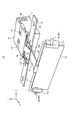
次に、図2乃至4を参照して、ヘッドアップディスプレイ10の構成を説明する。図2は、ヘッドアップディスプレイ10を斜め上方向から見た斜視図である。図3は、ヘッドアップディスプレイ10を上方から見た平面図であり、図4はヘッドアップディスプレイ10の側面図である。
なお、以下の説明において、「前後方向」とは、図2に示すX方向、即ち、光源部11とコンバイナ20とを結ぶ方向を指す。「左右方向」とは、図2に示すZ方向、即ち、コンバイナ20の長さ方向を指す。「上下方向」とは、図2に示すY方向、即ち、前後方向と左右方向の両方に垂直な方向を指す。
ヘッドアップディスプレイ10は、光源部11と、本体スライドプレート12と、カバー13と、スライドロック機構14と、取付プレート15と、センターアーム16と、保持アーム17と、調整用部材18とを備える。
光源部11には、レーザダイオードなどの光源(図示せず)が搭載されている。光源部11から出射した光はコンバイナ20へ投射される。コンバイナ20は、光源部11から出射された光を運転者7の目の方向へ反射する。
光源部11の天面上には本体スライドプレート12が配置されている。本体スライドプレート12は、光源部11の天面のコンバイナ20側の部分を覆うメイン部分12aと、コンバイナ20の方向へ張り出した張出部分12bとを有する。張出部分12bには、一対の長穴12cが設けられている。
本体スライドプレート12の上にはカバー13が配置されている。カバー13は、光源部11の天面及び側面を覆い、光源部11を保持する。カバー13は、光源部11の側面を覆う側面プレート13bを備え、側面プレート13bは光源部11の側面に対して例えばネジ止めなどにより固定される。
カバー13は天面に一対の切り込み部13aを有する。本体スライドプレート12のメイン部分12aは、カバー13の切り込み部13aよりもコンバイナ20側の部分において、カバー13に固定されている。よって、カバー13は、本体スライドプレート12と光源部11とを保持する。
スライドロック機構14は、カバー13の切り込み部13aに設けられ、光源部11の天面上に設けられた突起部がはめ込まれる複数の凹部を有する。突起部をはめ込む位置を調整することにより、カバー13に対する光源部11の前後方向の位置を調整することができる。
取付プレート15は、ヘッドアップディスプレイ10を車両に取り付ける際の土台となる部材である。本実施例では、取付プレート15は矩形の平板であり、複数の長穴15aが形成されている。取付プレート15は、車室の天井3に設けられた取付穴(図示せず)に対してネジにより固定される。
センターアーム16は、光源部11の略中央からコンバイナ20の方向へ延びるように光源部11に対して取り付けられている。センターアーム16は、保持アーム17を回動可能に保持する。
保持アーム17は、コンバイナ20を左右から保持する。具体的に、保持アーム17は、長さ方向の端部に一対の保持部17aを有し、一対の保持部17aはコンバイナ20を左右から保持する。保持アーム17はセンターアーム16に対して回動可能に取り付けられているので、図4の矢印51に示すように、保持アーム17により保持されたコンバイナ20は、保持アーム17の長さ方向を回転軸として、センターアーム16に対して前後方向に回動可能となっている。
保持アーム17の保持部17aには、筒状の調整用部材18が取り付けられている。詳細は後述するが、調整用部材18は、ヘッドアップディスプレイ10を車両1の天井3に取り付ける際に、コンバイナ20の位置を光源部11に対して前後方向及び左右方向に調整する際に使用される。
図3に示すように、ヘッドアップディスプレイ10を上方から見た平面において、調整用部材18の中心軸202は、前後方向(X方向)の軸201に対して角度αだけ内側を向いている。言い換えると、一対の調整用部材18は、光源部11に近い側のそれぞれの端部の距離が、光源部11に遠い側のそれぞれの端部の距離よりも短くなっている。この角度αは、平均的な車両におけるシートの位置(着座したユーザの頭の位置)とヘッドアップディスプレイ10の取付位置(通常は、運転席前方のサンバイザの位置など)との距離、及び、コンバイナ20の左右方向の長さなどに基づいて予め決定される。
また、図4に示すように、ヘッドアップディスプレイ10を側方から見た平面において、筒状の調整用部材18の中心軸302は、コンバイナ20の短辺方向301に対して略垂直となっている。これにより、ユーザ7が調整用部材18を見たときの視線は、光源より出射されコンバイナ20により反射された投射光に沿った方向となる。つまり、ユーザ7の視線は、調整用部材18を見ることにより、コンバイナ20によって反射された光に沿った方向で調整用部材18を透過する。
以上の構成において、コンバイナ20は本発明の光学素子の一例であり、本体スライドプレート12、カバー13、センターアーム16及び保持アーム18は本発明の調整機構の一例である。また、調整用部材18は本発明の観察調整用部材及び調整用部材の一例であり、保持アーム17は光学素子保持部材の一例である。
(取付位置調整方法)
次に、ヘッドアップディスプレイ10の取付位置の調整方法について説明する。
次に、ヘッドアップディスプレイ10の取付位置の調整方法について説明する。
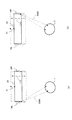
まず、調整用部材18の見え方について図7を参照して説明する。図7(a)に示すように、本実施例では、調整用部材18は、所定長さの筒状の部材である。調整用部材18は、内部に所定長さの孔18yが設けられており、光源部11側の端部は開放しており、光源部11から遠い方の底部にマーク18xが設けられている。ユーザ7は、マーク18xと反対側の端部から調整用部材18の孔18yを覗くように見る。
ユーザ7の視線が調整用部材18の中心軸方向と一致している場合、ユーザ7には調整用部材18は図7(b)に示す状態25aのように見える。一方、ユーザ7の視線が調整用部材18の中心軸方向からずれている場合、ユーザには調整用部材18は図7(c)に示す状態25b~25eのように見える。よって、ユーザ7は、コンバイナ20の位置を調整して調整用部材18が状態25aのように見える位置に配置する。
次に、具体的な調整方法について説明する。まず、ユーザ7は、図2乃至4に示すように一体化されたヘッドアップディスプレイ10を、取付プレート15を用いて車両1の天井3の取付位置に取り付ける。なお、天井3の取付位置とは、予め車体側に取付用のネジ穴が形成されている位置であり、例えばサンバイザの位置などである。
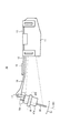
次に、まずコンバイナ20の左右方向の位置を決定する。具体的には、ユーザ7はシート5に座り、図5(a)に示すように、コンバイナ20の方向を見る。そして、コンバイナ20の長さ方向の中央に設けられた中央マーク21を見ながら、図5(b)に示すようにコンバイナ20を矢印100A、100Bに示す左右方向に移動させ、中央マーク21がユーザ7の左右の目の中央にくるようにコンバイナ20の左右方向の位置を決定する。
なお、コンバイナ20の左右方向の位置調整は、図2に示す取付プレート15に対する本体スライドプレート12の取付位置を調整することにより行われる。前述のように、取付プレート15は車両1の天井3に対して固定されている。また、コンバイナ20を含むヘッドアップディスプレイ10の他の構成要素は、本体スライドプレート12と一体化されている。よって、取付プレート15の長穴15aに対するネジ15bの位置を調整することにより、コンバイナ20の左右方向の位置を調整することができる。
次に、コンバイナ20の前後方向の位置を決定する。具体的には、図6(a)に示すように、ユーザは両目又は利き目を使用して左側の調整用部材18Lを見ながらコンバイナ20を前後方向(矢印300の方向)に移動し、調整用部材18が図7(b)に示す状態25aのように見える位置にコンバイナ20を配置する。続いて、ユーザは両目又は利き目を使用して右側の調整用部材18Rを見ながらコンバイナ20を前後方向300に移動し、調整部材18が状態25aのように見える位置にコンバイナ20を配置する。
次に、ユーザは左側の調整用部材18Lの見え方を確認する。直前の右側の調整用部材18Rを用いた調整により、左側の調整用部材18Lの見え方が変化し、状態25aのようになっていない場合には、再度コンバイナ20を前後方向に移動し、状態25aのように見えるようにする。次に、ユーザは右側の調整用部材18Rの見え方を確認する。こうして、ユーザ7は、左右の調整用部材18L、18Rがともに状態25aのように見える位置をコンバイナ20の適切な前後方向位置と決定する。
なお、コンバイナ20の前後方向の位置調整は、図2に示す取付プレート15に対する本体スライドプレート12の取付位置を調整することにより行われる。取付プレート15は車両1の天井3に対して固定されており、コンバイナ20を含むヘッドアップディスプレイ10の他の構成要素は、本体スライドプレート12と一体化されている。よって、本体スライドプレート12の長穴12cに対するネジ15bの位置を調整することにより、コンバイナ20の前後方向の位置を調整することができる。
また、コンバイナ20の前後方向の位置調整は、スライドロック機構14によっても行うことができる。具体的には、一体となっているカバー13及び本体スライドプレート12に対する光源部11の位置を、スライドロック機構14を操作して前後させることにより、アーム16を介して光源部11と一体化しているコンバイナ20を前後方向に移動させることができる。
その後、必要に応じて、ユーザ7は、コンバイナ20を保持する保持アーム17の角度を図4に示す矢印51の方向に微調整する。
このように、本実施例では、中央マーク21及び調整用部材18を設けたので、ユーザはこれらを見ながらコンバイナ20の左右方向位置及び前後方向位置を調整することができる。よって、コンバイナ20の位置を調整する際に、システムを起動し、光源から光を投射して画像を表示させる必要がない。
[変形例]
上記の実施例では、図4に示すように、調整用部材18をコンバイナ20の短辺方向の中央付近に設けているが、矢印51のようにコンバイナ20の角度を調整可能な構成とする場合には、その角度調整の影響を少なくするため、破線18xに示すように、調整用部材18を、保持アーム17が回動する軸の近傍に配置することがより好ましい。すなわち、コンバイナ20の角度を変更するための回転軸上の位置、またはその近傍が最適な位置といえる。
上記の実施例では、図4に示すように、調整用部材18をコンバイナ20の短辺方向の中央付近に設けているが、矢印51のようにコンバイナ20の角度を調整可能な構成とする場合には、その角度調整の影響を少なくするため、破線18xに示すように、調整用部材18を、保持アーム17が回動する軸の近傍に配置することがより好ましい。すなわち、コンバイナ20の角度を変更するための回転軸上の位置、またはその近傍が最適な位置といえる。
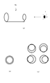
上記の実施例では、調整用部材18を筒状の部材で構成しているが、本発明の適用はこれには限らない。他の例による調整用部材18zを図8(a)に示す。この調整用部材18zは、径の異なる2つのリングを備える部材である。この場合、ユーザ7の視線が2つのリングの中心を結ぶ中心軸と一致している場合には、図8(b)に示すように、小さい方のリングが大きい方のリングの内側に同心円状に収まって見える。一方、ユーザ7の視線が2つのリングの中心軸からずれている場合には、図8(c)に示すように、2つのリングは交差して見えるか、交差していなくても同心円状には見えない。よって、ユーザ7は、前述した方法により、左右の調整用部材18zがともに図8(b)に示す状態となるように、コンバイナ20の前後方向の位置調整を行えばよい。
上記の実施例では、光源からの投射光をユーザ7の方向へ反射する光学素子としてコンバイナ20を設けているが、その代わりに車両のフロントガラスを利用することもできる。その場合には、ヘッドアップディスプレイ10はコンバイナ20を有さず、光源部と一体化したいずれかの部位に調整用部材18を取り付ける。ユーザは、光源部11と一体化した調整用部材18を見ながら光源部の左右方向、前後方向の位置調整を行う。
上記の実施例では、一対の調整用部材を設けているが、システムが持つ視認範囲の許容幅によっては、左右いずれか一方のみに調整用部材を設けることとしてもよい。
本発明は、透過型ディスプレイを用いたディスプレイシステムに利用することができる。特に、車両などの移動体に設置するヘッドアップディスプレイに利用することができる。
1 車両
3 天井
4 フロントガラス
7 運転者
10 ヘッドアップディスプレイ
11 光源部
12 本体スライドプレート
13 カバー
15 取付プレート
18 調整用部材
20 コンバイナ
30 虚像
3 天井
4 フロントガラス
7 運転者
10 ヘッドアップディスプレイ
11 光源部
12 本体スライドプレート
13 カバー
15 取付プレート
18 調整用部材
20 コンバイナ
30 虚像
Claims (13)
- 光源からの投射光を反射し、観察者により所定の位置から視認可能な虚像を形成するための光学素子と、
前記投射光と前記光学素子との位置関係又は角度関係を前記観察者が調整するための調整機構と、
前記調整機構による調整に応じて、前記観察者の前記光学素子への視線に対する位置又は角度が変化する観察調整用部材と、を備え、
前記観察調整用部材は、前記観察者の前記調整機構による調整に応じて、当該観察者からの見え方が特定のものとなるように構成されていることを特徴とする画像表示装置。 - 前記観察調整用部材は、前記光学素子により反射された投射光に沿った方向に光が透過可能に構成されていることを特徴とする請求項1に記載の画像表示装置。
- 前記観察調整用部材は、前記投射光の反射方向に沿った方向に設けられた所定の長さの孔を有する一対の調整用部材であることを特徴とする請求項1に記載の画像表示装置。
- 前記一対の調整用部材は、前記光学素子を保持する光学素子保持部材の長さ方向の両端に取り付けられていることを特徴とする請求項3に記載の画像表示装置。
- 前記一対の調整用部材は、前記光学素子を基準として、光源側の端部の距離が、光源と反対側の端部の距離よりも短くなるように配置されていることを特徴とする請求項4に記載の画像表示装置。
- 前記調整用部材を透過する光の透過方向が、前記光源側で交わるような角度で取り付けられていることを特徴とする請求項4に記載の画像表示装置。
- 前記一対の調整用部材は、光学素子の面に対して略垂直の角度で取り付けられていることを特徴とする請求項4に記載の画像表示装置。
- 前記光学素子保持部材は、前記光学素子の長さ方向に延びる回転軸に対して前記光学素子を回転可能に保持しており、
前記一対の調整用部材は、前記回転軸近傍に取り付けられていることを特徴とする請求項4に記載の画像表示装置。 - 前記光学素子の中央には調整用目印が設けられていることを特徴とする請求項1乃至8のいずれか一項に記載の画像表示装置。
- 前記光源を収容する光源部を備え、
前記観察調整用部材は、前記光学素子と前記光源部とを結ぶ方向である前後方向、及び、前記前後方向に対して垂直かつ前記光学素子の長さ方向に対して垂直な方向である上下方向に移動可能に構成されていることを特徴とする請求項1乃至9のいずれか一項に記載の画像表示装置。 - 光源を収容する光源部と、光源からの投射光を反射し、観察者により所定の位置から視認可能な虚像を形成するための光学素子と、前記投射光と前記光学素子との位置関係又は角度関係を前記観察者が調整するための調整機構と、前記調整機構による調整に応じて、前記観察者の前記光学素子への視線に対する位置又は角度が変化する観察調整用部材と、を備える画像表示装置の取付位置調整方法であって、
前記観察調整用部材を視認しつつ、前記光学素子と前記光源部とを結ぶ方向である前後方向に前記光学素子を移動させ、前記観察調整用部材の見え方が特定のものとなる位置を前記光学素子の位置と決定することを特徴とする画像表示装置の取付位置調整方法。 - 光を投射する光源と、
前記光源からの前記光を反射し、観察者により所定の位置から視認可能な虚像を形成するための光学素子と、
前記光源からの前記光の投射方向に対する前記光学素子の角度を前記観察者が調整するための調整機構と、
前記調整機構による調整に応じて、所定位置にいる前記観察者の前記光学素子への視線に対する位置又は角度が変化する観察調整用部材と、を備え、
前記観察調整用部材は、前記所定位置にいる観察者の視線を透過させる孔を有する筒形状であり、前記観察者の前記調整機構による調整に応じて、当該観察者が前記孔を通した反対側の見え方が変化することを特徴とする画像表示装置。 - 前記観察調整用部材は、前記光学素子の前記観察者にとっての左右方向の両端に取り付けられていることを特徴とする請求項12に記載の画像表示装置。
Priority Applications (2)
| Application Number | Priority Date | Filing Date | Title |
|---|---|---|---|
| JP2011546350A JP4945702B1 (ja) | 2011-03-30 | 2011-03-30 | 画像表示装置及びその取付位置調整方法 |
| PCT/JP2011/058056 WO2012131945A1 (ja) | 2011-03-30 | 2011-03-30 | 画像表示装置及びその取付位置調整方法 |
Applications Claiming Priority (1)
| Application Number | Priority Date | Filing Date | Title |
|---|---|---|---|
| PCT/JP2011/058056 WO2012131945A1 (ja) | 2011-03-30 | 2011-03-30 | 画像表示装置及びその取付位置調整方法 |
Publications (1)
| Publication Number | Publication Date |
|---|---|
| WO2012131945A1 true WO2012131945A1 (ja) | 2012-10-04 |
Family
ID=46498702
Family Applications (1)
| Application Number | Title | Priority Date | Filing Date |
|---|---|---|---|
| PCT/JP2011/058056 Ceased WO2012131945A1 (ja) | 2011-03-30 | 2011-03-30 | 画像表示装置及びその取付位置調整方法 |
Country Status (2)
| Country | Link |
|---|---|
| JP (1) | JP4945702B1 (ja) |
| WO (1) | WO2012131945A1 (ja) |
Cited By (3)
| Publication number | Priority date | Publication date | Assignee | Title |
|---|---|---|---|---|
| JP2014135570A (ja) * | 2013-01-08 | 2014-07-24 | Chugoku Electric Power Co Inc:The | 電波伝搬路点検装置 |
| JP2016034767A (ja) * | 2014-08-01 | 2016-03-17 | マツダ株式会社 | 自動車の運転席構造 |
| CN110398840A (zh) * | 2019-07-19 | 2019-11-01 | Oppo广东移动通信有限公司 | 调整光心距离的方法、头戴设备和存储介质 |
Families Citing this family (10)
| Publication number | Priority date | Publication date | Assignee | Title |
|---|---|---|---|---|
| JP5831370B2 (ja) * | 2012-06-29 | 2015-12-09 | 株式会社Jvcケンウッド | 車両用表示装置 |
| WO2014002397A1 (ja) * | 2012-06-29 | 2014-01-03 | 株式会社Jvcケンウッド | 車両用表示装置 |
| JP5954047B2 (ja) * | 2012-08-22 | 2016-07-20 | 株式会社Jvcケンウッド | 車両用表示装置 |
| WO2014049735A1 (ja) * | 2012-09-26 | 2014-04-03 | パイオニア株式会社 | ヘッドアップディスプレイ |
| WO2014049736A1 (ja) * | 2012-09-26 | 2014-04-03 | パイオニア株式会社 | ヘッドアップディスプレイ |
| JPWO2014049734A1 (ja) * | 2012-09-26 | 2016-08-22 | パイオニア株式会社 | ヘッドアップディスプレイ |
| WO2014049733A1 (ja) * | 2012-09-26 | 2014-04-03 | パイオニア株式会社 | ヘッドアップディスプレイ |
| WO2014049732A1 (ja) * | 2012-09-26 | 2014-04-03 | パイオニア株式会社 | ヘッドアップディスプレイ |
| WO2015019401A1 (ja) * | 2013-08-05 | 2015-02-12 | パイオニア株式会社 | 虚像表示装置 |
| US9488835B2 (en) | 2013-08-29 | 2016-11-08 | Pioneer Corporation | Virtual image display device and attachment device |
Citations (4)
| Publication number | Priority date | Publication date | Assignee | Title |
|---|---|---|---|---|
| JPH0526589U (ja) * | 1991-09-24 | 1993-04-06 | 富士通株式会社 | ヘツドアツプデイスプレイ装置 |
| JP2006015941A (ja) * | 2004-07-05 | 2006-01-19 | Yazaki Corp | 車両用表示装置 |
| JP2006224919A (ja) * | 2005-02-21 | 2006-08-31 | Yazaki Corp | 車両用虚像表示装置 |
| JP2010262161A (ja) * | 2009-05-08 | 2010-11-18 | Toshiba Corp | 表示装置、表示方法及び車両 |
Family Cites Families (1)
| Publication number | Priority date | Publication date | Assignee | Title |
|---|---|---|---|---|
| JP3652838B2 (ja) * | 1997-06-11 | 2005-05-25 | 株式会社リコー | 画像表示装置 |
-
2011
- 2011-03-30 JP JP2011546350A patent/JP4945702B1/ja not_active Expired - Fee Related
- 2011-03-30 WO PCT/JP2011/058056 patent/WO2012131945A1/ja not_active Ceased
Patent Citations (4)
| Publication number | Priority date | Publication date | Assignee | Title |
|---|---|---|---|---|
| JPH0526589U (ja) * | 1991-09-24 | 1993-04-06 | 富士通株式会社 | ヘツドアツプデイスプレイ装置 |
| JP2006015941A (ja) * | 2004-07-05 | 2006-01-19 | Yazaki Corp | 車両用表示装置 |
| JP2006224919A (ja) * | 2005-02-21 | 2006-08-31 | Yazaki Corp | 車両用虚像表示装置 |
| JP2010262161A (ja) * | 2009-05-08 | 2010-11-18 | Toshiba Corp | 表示装置、表示方法及び車両 |
Cited By (4)
| Publication number | Priority date | Publication date | Assignee | Title |
|---|---|---|---|---|
| JP2014135570A (ja) * | 2013-01-08 | 2014-07-24 | Chugoku Electric Power Co Inc:The | 電波伝搬路点検装置 |
| JP2016034767A (ja) * | 2014-08-01 | 2016-03-17 | マツダ株式会社 | 自動車の運転席構造 |
| CN110398840A (zh) * | 2019-07-19 | 2019-11-01 | Oppo广东移动通信有限公司 | 调整光心距离的方法、头戴设备和存储介质 |
| CN110398840B (zh) * | 2019-07-19 | 2021-10-15 | Oppo广东移动通信有限公司 | 调整光心距离的方法、头戴设备和存储介质 |
Also Published As
| Publication number | Publication date |
|---|---|
| JP4945702B1 (ja) | 2012-06-06 |
| JPWO2012131945A1 (ja) | 2014-07-24 |
Similar Documents
| Publication | Publication Date | Title |
|---|---|---|
| JP4945702B1 (ja) | 画像表示装置及びその取付位置調整方法 | |
| JP5777672B2 (ja) | ヘッドアップ投影システム | |
| JP6458998B2 (ja) | ヘッドアップディスプレイ | |
| US7659868B2 (en) | Head-up display apparatus and cover-mirror unit used for the same | |
| JP4336245B2 (ja) | ヘッドアップディスプレイ装置 | |
| EP2869114B1 (en) | Image display device | |
| JP5741251B2 (ja) | 虚像表示装置 | |
| EP3828619B1 (en) | Virtual image display device | |
| KR101640579B1 (ko) | 헤드업 디스플레이 | |
| JP4223942B2 (ja) | ヘッドアップディスプレイ装置 | |
| JP2018501510A (ja) | 自動車のヘッドアップディスプレイ | |
| WO2014049733A1 (ja) | ヘッドアップディスプレイ | |
| JP2015045690A (ja) | ヘッドアップディスプレイ及び投影装置 | |
| JP2009222882A (ja) | ヘッドアップディスプレイ装置 | |
| JP2019011774A (ja) | 機器固定装置および前記機器固定装置を使用した機器の固定方法 | |
| JP3202990U (ja) | 手動式反射シート装置 | |
| KR20080007772A (ko) | Hud 시스템 | |
| JP2019144369A (ja) | 平面鏡ユニット | |
| KR102087804B1 (ko) | 허상 표시 장치 | |
| WO2012117496A1 (ja) | 表示装置 | |
| WO2014049734A1 (ja) | ヘッドアップディスプレイ | |
| WO2014049732A1 (ja) | ヘッドアップディスプレイ | |
| JP2006069266A (ja) | 車両用表示装置及びそのミラー角度調整方法 | |
| KR101510988B1 (ko) | 헤드업 디스플레이 장치 | |
| CN221079071U (zh) | 镜片支架、显示设备及交通工具 |
Legal Events
| Date | Code | Title | Description |
|---|---|---|---|
| ENP | Entry into the national phase |
Ref document number: 2011546350 Country of ref document: JP Kind code of ref document: A |
|
| 121 | Ep: the epo has been informed by wipo that ep was designated in this application |
Ref document number: 11862005 Country of ref document: EP Kind code of ref document: A1 |
|
| NENP | Non-entry into the national phase |
Ref country code: DE |
|
| 122 | Ep: pct application non-entry in european phase |
Ref document number: 11862005 Country of ref document: EP Kind code of ref document: A1 |