WO2012131936A1 - 音声信号処理装置及び音声信号処理プログラム - Google Patents
音声信号処理装置及び音声信号処理プログラム Download PDFInfo
- Publication number
- WO2012131936A1 WO2012131936A1 PCT/JP2011/058015 JP2011058015W WO2012131936A1 WO 2012131936 A1 WO2012131936 A1 WO 2012131936A1 JP 2011058015 W JP2011058015 W JP 2011058015W WO 2012131936 A1 WO2012131936 A1 WO 2012131936A1
- Authority
- WO
- WIPO (PCT)
- Prior art keywords
- signal
- level
- front channel
- surround
- signal processing
- Prior art date
- Legal status (The legal status is an assumption and is not a legal conclusion. Google has not performed a legal analysis and makes no representation as to the accuracy of the status listed.)
- Ceased
Links
Images

Classifications
-
- H—ELECTRICITY
- H04—ELECTRIC COMMUNICATION TECHNIQUE
- H04S—STEREOPHONIC SYSTEMS
- H04S3/00—Systems employing more than two channels, e.g. quadraphonic
- H04S3/008—Systems employing more than two channels, e.g. quadraphonic in which the audio signals are in digital form, i.e. employing more than two discrete digital channels
-
- H—ELECTRICITY
- H04—ELECTRIC COMMUNICATION TECHNIQUE
- H04S—STEREOPHONIC SYSTEMS
- H04S5/00—Pseudo-stereo systems, e.g. in which additional channel signals are derived from monophonic signals by means of phase shifting, time delay or reverberation
- H04S5/02—Pseudo-stereo systems, e.g. in which additional channel signals are derived from monophonic signals by means of phase shifting, time delay or reverberation of the pseudo four-channel type, e.g. in which rear channel signals are derived from two-channel stereo signals
-
- H—ELECTRICITY
- H04—ELECTRIC COMMUNICATION TECHNIQUE
- H04S—STEREOPHONIC SYSTEMS
- H04S3/00—Systems employing more than two channels, e.g. quadraphonic
- H04S3/02—Systems employing more than two channels, e.g. quadraphonic of the matrix type, i.e. in which input signals are combined algebraically, e.g. after having been phase shifted with respect to each other
-
- H—ELECTRICITY
- H04—ELECTRIC COMMUNICATION TECHNIQUE
- H04S—STEREOPHONIC SYSTEMS
- H04S2400/00—Details of stereophonic systems covered by H04S but not provided for in its groups
- H04S2400/03—Aspects of down-mixing multi-channel audio to configurations with lower numbers of playback channels, e.g. 7.1 -> 5.1
Definitions
- the present invention relates to processing of multi-channel audio signals.
- Patent Document 1 proposes a method of extracting localization information from a two-channel signal and making it into four channels.
- An object of the present invention is to realize powerful and realistic sound reproduction by performing signal processing on a multi-channel signal.
- the invention according to claim 1 is an audio signal processing device, an input unit that receives an input signal including a front channel signal and a surround channel signal, and a level detection that detects an increase in level of the front channel signal over a predetermined ratio. And means for adding a front channel signal to a surround channel signal over a predetermined time when an increase in level of the predetermined ratio or more is detected.
- the invention according to claim 10 is an audio signal processing program executed in an apparatus including a computer, wherein the input means receives an input signal including a front channel signal and a surround channel signal, and a predetermined ratio or more of the front channel signal.
- the computer is caused to function as level detection means for detecting an increase in level, and addition means for adding a front channel signal to a surround channel signal over a predetermined time when a level increase of the predetermined ratio or more is detected. To do.
- the audio signal processing apparatus includes an input unit that receives an input signal including a front channel signal and a surround channel signal, and a level detection unit that detects a level increase of the front channel signal by a predetermined ratio or more. Adding means for adding a front channel signal to a surround channel signal over a predetermined time when an increase in level of the predetermined ratio or more is detected.
- the above audio signal processing device receives the front channel signal and the surround channel signal, and detects the level of the front channel signal.
- the front channel signal is added to the surround channel signal over a certain period of time.
- a steep change in the front channel signal caused by sound effects can be reflected in the surround channel, and the force and presence can be improved.
- One aspect of the audio signal processing apparatus includes level control means for controlling an addition level, which is a level of a front channel signal added to the surround channel signal, based on the level increase rate.
- the level control means increases the addition level as the level increase rate increases.
- the larger the rate of level increase the greater the change in the surround channel is reflected. Therefore, the surround channel is changed at an appropriate level according to the magnitude of the change in the front channel.
- the level control means decreases the addition level during the fixed time so that the addition level becomes zero when the fixed time elapses.
- the process of reflecting the change in the front channel on the surround channel is terminated in a certain time, so that the effect can be ensured every time such a change occurs. Also, the sense of incongruity can be eliminated by gradually decreasing the level.
- the level detection means determines that the ratio between the current level of the front channel signal and the level in the immediately preceding predetermined period is equal to or greater than a predetermined value. This is detected as an increase in level. Thereby, a steep change in level in the front channel can be accurately detected.
- the front channel signal includes left and right front channel signals
- the level detecting means detects the level increase of a difference signal between the left and right front channel signals.
- the difference signal between the left and right front channel signals it is possible to prevent the line components normally included in the left and right in-phase of the front channel signal from being mixed into the surround channel.
- the front channel signal includes left and right front channel signals
- the level detection means includes a low frequency component of a sum signal of the left and right front channel signals
- the level increase is detected for the addition signal with the high frequency component of the difference signal between the left and right front channel signals.
- only the low frequency component is used for the sum signal of the front channel signal, thereby preventing middle and high frequency serif components included in the front channel signal from being mixed with the surround channel.
- the front channel signal includes left and right front channel signals
- the level detection unit is configured to detect the low frequency component of the sum signal of the left and right front channel signals. Detect level increase.
- the middle and high frequency serif components included in the front channel signal from being mixed into the surround channel.
- the front channel signal includes left and right front channel signals
- the surround channel signal includes left and right surround channel signals
- the adding means includes the left and right front channel signals. Is added to one of the left and right surround signals in the positive phase and added to the other of the left and right surround signals in the reverse phase.
- the force and the sense of presence can be further improved.
- an audio signal processing program executed in an apparatus including a computer includes input means for receiving an input signal including a front channel signal and a surround channel signal, and a predetermined ratio or more of the front channel signal.
- the computer is caused to function as level detection means for detecting an increase in level, and addition means for adding a front channel signal to a surround channel signal for a predetermined time when a level increase of the predetermined ratio or more is detected.
- An audio signal reproduction device can be realized by executing the above program by a computer.
- FIG. 1 is a block diagram showing the configuration of an audio signal reproduction apparatus to which an audio signal processing apparatus of the present invention is applied.
- the audio signal reproduction apparatus 1 includes a decoder 2, a signal processing unit 100 that is an embodiment of the audio signal processing apparatus according to the present invention, and a D / A converter 3.
- the decoder 2 receives the compressed stream ST from the signal source.
- Examples of the signal source include a DVD, a BD, and a hard disk recorder.
- the video signal and the audio signal are recorded on these recording media, but the decoder 2 may receive a compressed stream including the video signal and the audio signal, or may receive a compressed stream of only the audio signal.
- the decoder 2 decodes the received compressed stream ST and generates a digital audio signal. Specifically, the decoder 2 generates a left front channel signal FL, a right front channel signal FR, a left surround channel signal SL, a right surround channel signal SR, a center channel signal C, and an LFE (Low Frequency Effect) signal LFE, The signal is supplied to the signal processing unit 100.
- channel is also expressed as “ch”.
- the signal processing unit 100 performs signal processing on the surround ch signal based on the input signal, and supplies the processed signal to the D / A converter 3. Specifically, the signal processing unit 100 outputs the front ch signals FL and FR, the center ch signal C, and the LFE signal LFE as they are to the D / A converter 3, and the surround ch signal SLx obtained by the signal processing and SRx is output to the D / A converter 3. This signal processing will be described later in detail.
- the D / A converter 3 D / A converts the received signals FL, FR, SLx, SRx, C, and LFE, respectively, and outputs analog signals AFL, AFR, ASLx, ASRx, AC, and ALFE to the speakers of each channel. To do.
- the signal processing unit 100 detects a steep rise of the front ch signal, specifically, a level increase of a predetermined ratio or more, and mixes (adds) the front ch signal to the surround ch signal when the steep rise is detected. To do.
- this processing is also referred to as “front ch signal mixing processing”.
- the front ch signal mixing process improves the force and presence by spreading a steep change in the input signal level to the rear of the sound field. Details will be described below.
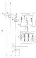
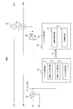
- FIG. 2 is a block diagram showing the configuration of the basic embodiment of the signal processing unit 100.
- the signal processing unit 100 performs processing for adding the front ch signal to the surround ch signal, and the front ch signals FL and FR, the center ch signal C, and the LFE signal are input signals. Since the data is output as it is, the configuration of that portion is omitted.
- the signal processing unit 100 includes a level detection unit 10, a level control unit 20, adders 31, 32, and 33, and an amplifier 40.
- the surround ch signal SL is input to the adder 32, and the surround ch signal SR is input to the adder 33.
- the amplifier 40 amplifies the front ch signal F based on the addition coefficient ⁇ supplied from the level control unit 20 to generate a signal ⁇ (FL + FR), and supplies it to the adders 32 and 33.
- the addition coefficient ⁇ indicates the level of the front ch signal added to the surround ch signal (referred to as “addition level”). As the addition coefficient ⁇ increases, the level of the front ch signal added to the surround ch signal increases.
- the adder 32 adds the signal ⁇ (FL + FR) to the front ch signal SL and outputs it as a surround ch signal SLx.
- the adder 33 adds the signal ⁇ (FL + FR) to the front ch signal SR and outputs it as a surround ch signal SRx.
- the level detection unit 10 and the level control unit 20 have a role of controlling the addition coefficient ⁇ based on the level of the front ch signal F.
- the level detection unit 10 includes a past level holding unit 11, a current level detection unit 12, and a level ratio calculation unit 13.
- the level control unit 20 includes an addition coefficient determination unit 21 and a coefficient reduction unit 22.
- the current level detection unit 12 detects the level of the front ch signal F and holds it as the current level Lc.
- the past level holding unit 11 holds the level of the front ch signal F in a predetermined period immediately before the present. That is, the past level holding unit 11 always holds the level of the front ch signal F detected by the current level detecting unit 12 for a predetermined period.
- the “predetermined period” is set to several seconds (for example, about 5 to 8 seconds).
- the past level holding unit 11 determines a past level Lp that represents the level of the front ch signal F during a predetermined period.
- the past level Lp can be, for example, the average value of the front ch signal F in a predetermined period, or the average value of the absolute value of the front ch signal at each time point or the maximum value of the absolute values.
- the level ratio R indicates the level change of the front ch signal F, and the level increase of the front ch signal F increases as the value of the level ratio R increases.
- the addition coefficient determination unit 21 of the level control unit 20 determines the addition coefficient ⁇ based on the level ratio R supplied from the level detection unit 10.
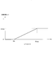
- FIG. 3 shows an example of the relationship between the level ratio R and the addition coefficient ⁇ .
- a threshold Rth of the level ratio R is prepared.
- This embodiment intends to add the front ch signal F to the surround ch signal when the level increase of the front ch signal is steep.
- the threshold value Rth indicates a predetermined ratio at which the level change of the front ch signal F is determined to be steep.
- the addition coefficient determination unit 21 determines that the level increase of the front ch signal F is not steep, and sets the addition coefficient ⁇ to “0”. Thereby, the front ch signal F is not added to the surround signal.
- the addition coefficient determination unit 21 determines that the level increase of the front ch signal F is steep, and sets the addition coefficient ⁇ to a value greater than “0”. As a result, the front ch signal F is added to the surround ch signal at a rate corresponding to the addition coefficient ⁇ .
- the threshold value Rth can be determined by experiments using various audio signal sources, and can be set to about “2 to 3”, for example. When the threshold value Rth is set to “2”, it is determined that the level increase is steep when the level of the front ch signal F is doubled.
- the addition coefficient ⁇ increases in proportion to the level ratio R. That is, as the level change of the front ch signal F becomes steeper, the level of the front ch signal F added to the surround ch signal, that is, the addition level increases.
- the level control unit 20 transmits a large change to the surround ch when the level change of the front ch signal F is large, and sets the change of the surround ch to an appropriate level when the level change is small. Thereby, the effect of a continuous and wide dynamic range can be acquired.
- a maximum value ⁇ max is set for the addition coefficient ⁇ .
- the maximum value ⁇ max of the addition coefficient is set to “0.5”, 1/2 or more of the front channel signal is not mixed with the surround ch. That is, even when the level change of the front ch signal F is large, the front ch signal F is not mixed with the surround ch signal without limitation. In this way, it is possible to prevent an uncomfortable feeling in the sound field due to excessive mixing processing.
- the coefficient reduction unit 22 has a role of limiting the time for mixing the front ch signal F to the surround ch signal to a certain time. Specifically, the coefficient reduction unit 22 has a predetermined time “ ⁇ ”. When the level ratio R becomes equal to or greater than the threshold value Rth, the addition coefficient determination unit 21 sets the addition coefficient ⁇ to a value larger than “0”, and the coefficient decreases when the front ch signal F is added to the surround ch signal by the amplifier 40. The unit 22 linearly decreases the addition coefficient ⁇ to “0” within a predetermined time ⁇ from the time when the front ch signal F starts to be added to the surround ch signal.
- the front ch signal F has a steep level increase
- the front ch signal F is added to the surround ch signal at a rate corresponding to the addition coefficient ⁇ , but thereafter the level of the front ch signal F that is gradually added. Decrease.
- the front ch signal F is not added to the surround ch signal.
- the effect of adding the front ch signal when the steep level increase of the front ch signal F occurs next is secured. Further, the effect can be reduced without a sense of incongruity by gradually reducing the ratio of adding the front ch signal F over a certain period of time.
- This fixed time “ ⁇ ” is set to about 1 to 1.5 seconds, for example.
- the predetermined time ⁇ is shorter than a predetermined time (7 to 8 seconds in the above example) that the past level holding unit 11 of the level detecting unit 10 holds the past level.
- the time of the past level holding unit 11 is a fixed time. About 5 to 6 times ⁇ is preferable.
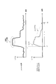
- FIG. 4 shows an example of the waveform of the front ch signal and the signal mixed with the surround ch signal by the above processing.
- the front ch signal is mixed with the surround ch signal at a rate corresponding to the addition coefficient ⁇ .
- the addition coefficient ⁇ gradually decreases, and the signal mixed with the surround ch signal gradually fades out.
- the addition coefficient ⁇ becomes “0”, and mixing of the front ch signal into the surround ch signal is stopped.
- the signal processing unit 100 performs the same processing. That is, the level control unit 20 determines the addition coefficient ⁇ based on the level ratio R at that time, and mixes the front ch signal with the surround ch signal for a certain time ⁇ .
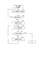
- FIG. 5 shows a flowchart of the front ch signal mixing process. This process is realized by a computer constituting the signal processing unit 100 executing a program prepared in advance and operating as each component shown in FIG.
- the level detection unit 10 detects the level of the front ch signal (step S11), and determines whether or not there is a steep level increase (step S12). When there is no steep level increase (step S12; No), the process returns to step S11. When there is a steep level increase (step S12; Yes), the level control unit 20 determines the addition coefficient ⁇ based on the level ratio R at that time (step S13). Then, the level control unit 20 supplies the addition coefficient ⁇ to the amplifier 40, thereby mixing the front ch signal with the surround ch signal (step S14).
- the level control unit 20 determines whether or not a certain period ⁇ has elapsed since the start of mixing of the front ch signals (step S15).
- the level control unit 20 gradually decreases the addition coefficient ⁇ (step S16), and continues to mix the front ch signals (step S14).
- the process ends.
- the dynamic change of the volume occurring in the sound field on the front side of the listening room can be converted into the dynamic change of the front and rear sound fields of the entire listening room, and before and after the sound field.
- the front ch signal includes a sound effect such as an explosion sound, it can also be output from a surround speaker. In this way, it is possible to improve the force and sense of presence, improve the sense of movement of sound and the connection of sounds, and integrate the entire sound field.
- this process is very consistent with 3D video in terms of the connection between the front and rear sound fields and a sense of movement, and it is possible to give the viewer a higher level of realism.
- the front ch signal F output from the amplifier 40 is added to the surround ch signals SL and SR by the adders 32 and 33. At this time, it is normal to add the front ch signal F in the positive phase to the surround ch signals SL and SR. Instead, the front ch signal F may be added in the normal phase to one of the left and right surround ch signals SL and SR, and the front ch signal F may be added in the opposite phase to the other. As a result, the effects such as the above-mentioned power and improvement of the sense of reality can be emphasized, and a wide spatial expression can be realized.
- the front ch signal may include speech, that is, human voice.
- speech that is, human voice.
- the amplitude of the front ch signal greatly changes depending on the presence or absence of a line. Therefore, if a sharp level increase due to the line is detected by the above-described front ch signal mixing process, the line is mixed with the surround ch signal. is there. Therefore, an example of a method for removing the influence of the lines included in the front ch signal while using the above front ch signal mixing process as a base will be described below.
- the front ch signal F used in the above-described front ch signal mixing process is a difference signal between the left and right front ch signals.
- the serif component is included in the left and right front ch signals in the same phase and at the same level, so the serif component is canceled in the difference signal between the left and right front ch signals. Therefore, the serif component is removed from the front ch signal mixed with the surround ch signal.
- FIG. 6 is a block diagram showing a configuration of the signal processing unit 100a according to the first example.
- the signal processing unit 100 a is the same as the signal processing unit 100 except that an adder 35 is provided instead of the adder 31 in the signal processing unit 100. It has the composition of.
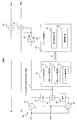
- the frequency component of the serif component is determined to some extent, and it is only the frequency band where the serif exists that needs to be removed. Therefore, in the second example, a crossover network filter is provided, and the band of the front ch signal is divided into two. Then, a difference signal is generated only for the high frequency side signal.
- FIG. 7 is a block diagram illustrating a configuration of the signal processing unit 100b according to the second example.
- the signal processing unit 100 b includes a crossover network circuit 50 instead of the adder 31 of the signal processing unit 100.
- the crossover network circuit 50 includes adders 41, 42, 43, a low-pass filter (LPF) 44, and a high-pass filter (HPF) 45.
- the band of the serif component is 500 Hz or more, and the cut-off frequency fc of the LPF 44 and the HPF 45 is about 500 Hz.
- the adder 41 generates a sum signal of the front ch signals FL and FR, and the LPF 44 supplies the low frequency component of this sum signal to the adder 43.
- the adder 42 generates a difference signal between the front ch signals FL and FR, and the HPF 45 supplies the high frequency component of the difference signal to the adder 43.
- the circuit configuration is complicated by adding the crossover network circuit.
- the front ch signal mixing process is simply performed using only the low frequency component of the sum signal of the front ch signals FL and FR. As a result, the circuit configuration can be simplified.
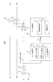
- FIG. 8 is a block diagram illustrating a configuration of the signal processing unit 100c according to the third example.
- the LPF 48 is inserted after the adder 31.
- the LPF 48 supplies only the low frequency component of the sum signal of the front ch signals SL and SR output from the adder 31 to the level detection unit 10 and the amplifier 40.
- the cut-off frequency fc of the LPF 48 is about 500 Hz.
- the influence of words can be removed with a simple configuration. In this method, the high frequency component of the front channel signal is not mixed with the surround channel signal. However, since the sound effect targeted by this system usually contains a lot of low frequency components, it is compared with the basic example. Therefore, the effect of mixing the front ch signals is not greatly reduced.
- steering processing employed in, for example, Dolby Pro Logic (registered trademark) is performed.
- a signal obtained by removing the speech component from the front ch signal may be generated, and the front ch signal mixing process may be performed using the signal.
- the system of the present invention can also be applied to a front 2 ch or 3 ch system capable of generating a pseudo surround channel.
- the pseudo surround channel is a channel that is output by processing the signal so that the surround ch signal is actually output from the front speaker but can be heard from the position of the surround speaker (that is, rearward). If this method is used, the present invention can be applied to a front 2ch system such as a TV or a front 3ch system such as a TV rack.
- the present invention can be used for an apparatus that reproduces a multi-channel audio signal together with video, such as an AV receiver, a general TV, a DVD / BD player, and the like.
Landscapes
- Engineering & Computer Science (AREA)
- Physics & Mathematics (AREA)
- Acoustics & Sound (AREA)
- Signal Processing (AREA)
- Mathematical Analysis (AREA)
- General Physics & Mathematics (AREA)
- Algebra (AREA)
- Mathematical Optimization (AREA)
- Mathematical Physics (AREA)
- Pure & Applied Mathematics (AREA)
- Theoretical Computer Science (AREA)
- Multimedia (AREA)
- Stereophonic System (AREA)
Abstract
音声信号処理装置は、フロントチャンネル信号とサラウンドチャンネル信号とを受け取り、フロントチャンネル信号のレベルを検出する。フロントチャンネル信号のレベルが所定の割合以上に変化するレベル増加が検出されると、一定時間にわたり、フロントチャンネル信号がサラウンドチャンネル信号に加算される。これにより、例えば効果音などに起因するフロントチャンネル信号の急峻な変化をサラウンドチャンネルに反映することができ、迫力や臨場感を向上させることができる。
Description
本発明は、マルチチャンネル音声信号の処理に関する。
映像ソースとともに再生される音声信号として、5.1チャンネルなどのマルチチャンネル音声信号を用いて立体感のある音声再生を行う手法が知られている。また、近年注目されている3D映像の再生システムにおいても、臨場感のある音声再生が求められている。
このような観点から、信号ソースから得られるマルチチャンネル音声信号に対して各種の信号処理を施す手法が提案されている。例えば、特許文献1では、2チャンネル信号から定位情報を抽出して、4チャンネル化する手法が提案されている。
本発明が解決しようとする課題としては、上記のものが例として挙げられる。本発明は、マルチチャンネル信号に対して信号処理を施すことにより、迫力、臨場感のある音声再生を実現することを目的とする。
請求項1に記載の発明は、音声信号処理装置であって、フロントチャンネル信号及びサラウンドチャンネル信号を含む入力信号を受け取る入力部と、前記フロントチャンネル信号の所定割合以上のレベル増加を検出するレベル検出手段と、前記所定割合以上のレベル増加が検出されたときに、一定時間にわたり、サラウンドチャンネル信号にフロントチャンネル信号を加算する加算手段と、を備えることを特徴とする。
請求項10に記載の発明は、コンピュータを備える装置において実行される音声信号処理プログラムであって、フロントチャンネル信号及びサラウンドチャンネル信号を含む入力信号を受け取る入力手段、前記フロントチャンネル信号の所定割合以上のレベル増加を検出するレベル検出手段、前記所定割合以上のレベル増加が検出されたときに、一定時間にわたり、サラウンドチャンネル信号にフロントチャンネル信号を加算する加算手段、として前記コンピュータを機能させることを特徴とする。
本発明の好適な実施形態では、音声信号処理装置は、フロントチャンネル信号及びサラウンドチャンネル信号を含む入力信号を受け取る入力部と、前記フロントチャンネル信号の所定割合以上のレベル増加を検出するレベル検出手段と、前記所定割合以上のレベル増加が検出されたときに、一定時間にわたり、サラウンドチャンネル信号にフロントチャンネル信号を加算する加算手段と、を備える。
上記の音声信号処理装置は、フロントチャンネル信号とサラウンドチャンネル信号とを受け取り、フロントチャンネル信号のレベルを検出する。フロントチャンネル信号のレベルが所定の割合以上に変化するレベル増加が検出されると、一定時間にわたり、フロントチャンネル信号がサラウンドチャンネル信号に加算される。これにより、例えば効果音などに起因するフロントチャンネル信号の急峻な変化をサラウンドチャンネルに反映することができ、迫力や臨場感を向上させることができる。
上記の音声信号処理装置の一態様は、前記レベル増加の割合に基づいて、前記サラウンドチャンネル信号に加算されるフロントチャンネル信号のレベルである加算レベルを制御するレベル制御手段を備える。好適な例では、前記レベル制御手段は、前記レベル増加の割合が大きいほど、前記加算レベルを大きくする。この態様では、レベル増加の割合が大きいほど、その変化がサラウンドチャンネル大きく反映されるので、フロントチャンネルの変化の大きさに応じて適切なレベルでサラウンドチャンネルに変化が与えられる。
上記の音声信号処理装置の他の一態様では、前記レベル制御手段は、前記一定時間の経過時に前記加算レベルがゼロとなるように、前記一定時間中に前記加算レベルを減少させる。この態様では、フロントチャンネルの変化をサラウンドチャンネルに反映する処理を一定の時間で終了させることにより、そのような変化が発生するたびに、効果を確保することが可能となる。また、徐々にレベルを減少させることにより違和感をなくすことができる。
上記の音声信号処理装置の他の一態様では、前記レベル検出手段は、前記フロントチャンネル信号の現在のレベルと直前の所定期間におけるレベルとの比が所定値以上となったことを、前記所定割合以上のレベル増加として検出する。これにより、フロントチャンネルにおけるレベルの急峻な変化を的確に検出することができる。
上記の音声信号処理装置の他の一態様では、前記フロントチャンネル信号は左右のフロントチャンネル信号を含み、前記レベル検出手段は、左右のフロントチャンネル信号の差信号について、前記レベル増加を検出する。この態様では、左右のフロントチャンネル信号の差信号を利用することにより、フロントチャンネル信号の通常左右同相に含まれるセリフの成分がサラウンドチャンネルに混合されることが防止される。
また、上記の音声信号処理装置の他の一態様では、前記フロントチャンネル信号は左右のフロントチャンネル信号を含み、前記レベル検出手段は、前記左右のフロントチャンネル信号の和信号の低域成分と、前記左右のフロントチャンネル信号の差信号の高域成分との加算信号について、前記レベル増加を検出する。この態様では、フロントチャンネル信号の和信号については、低域成分のみを利用することにより、フロントチャンネル信号に含まれる中高域のセリフの成分がサラウンドチャンネルに混合されることが防止される。
また、上記の音声信号処理装置の他の一態様では、前記フロントチャンネル信号は左右のフロントチャンネル信号を含み、前記レベル検出手段は、前記左右のフロントチャンネル信号の和信号の低域成分について、前記レベル増加を検出する。この態様では、左右のフロントチャンネル信号の和信号の低域成分のみを利用することにより、フロントチャンネル信号に含まれる中高域のセリフの成分がサラウンドチャンネルに混合されることが防止される。
上記の音声信号処理装置の他の一態様では、前記フロントチャンネル信号は左右のフロントチャンネル信号を含み、前記サラウンドチャンネル信号は左右のサラウンドチャンネル信号を含み、前記加算手段は、前記左右のフロントチャンネル信号の和信号を、前記左右のサラウンド信号の一方に正相で加算するとともに前記左右のサラウンド信号の他方に逆相で加算する。この態様では、フロントチャンネル信号の和信号を、左右のサラウンドチャンネル信号にそれぞれ正相と逆相で混合することにより、迫力や臨場感をより一層向上させることができる。
本発明の他の好適な実施形態では、コンピュータを備える装置において実行される音声信号処理プログラムは、フロントチャンネル信号及びサラウンドチャンネル信号を含む入力信号を受け取る入力手段、前記フロントチャンネル信号の所定割合以上のレベル増加を検出するレベル検出手段、前記所定割合以上のレベル増加が検出されたときに、一定時間にわたり、サラウンドチャンネル信号にフロントチャンネル信号を加算する加算手段、として前記コンピュータを機能させる。上記のプログラムをコンピュータにより実行することによって、音声信号再生装置を実現することができる。
以下、図面を参照して本発明の好適な実施例について説明する。
[全体構成]
図1は、本発明の音声信号処理装置を適用した音声信号再生装置の構成を示すブロック図である。音声信号再生装置1は、デコーダ2と、本発明に係る音声信号処理装置の実施例である信号処理部100と、D/A変換器3とを備える。
図1は、本発明の音声信号処理装置を適用した音声信号再生装置の構成を示すブロック図である。音声信号再生装置1は、デコーダ2と、本発明に係る音声信号処理装置の実施例である信号処理部100と、D/A変換器3とを備える。
デコーダ2は、信号ソースから圧縮ストリームSTを受け取る。信号ソースとしては、例えばDVD、BD、ハードディスクレコーダなどが挙げられる。これらの記録媒体には映像信号と音声信号とが記録されるが、デコーダ2は映像信号と音声信号とを含む圧縮ストリームを受け取ってもよいし、音声信号のみの圧縮ストリームを受け取ってもよい。
デコーダ2は、受け取った圧縮ストリームSTを復号化し、ディジタルの音声信号を生成する。具体的には、デコーダ2は、左フロントチャンネル信号FL、右フロントチャンネル信号FR、左サラウンドチャンネル信号SL、右サラウンドチャンネル信号SR、センターチャンネル信号C及びLFE(Low Frequency Effect)信号LFEを生成し、信号処理部100へ供給する。以下、「チャンネル」を「ch」とも表記する。
信号処理部100は、入力された信号に基づいて、サラウンドch信号に対する信号処理を行い、処理後の信号をD/A変換器3へ供給する。具体的には、信号処理部100は、フロントch信号FL及びFR、センターch信号C及びLFE信号LFEをそのままD/A変換器3へ出力するとともに、信号処理により得られたサラウンドch信号SLx及びSRxをD/A変換器3へ出力する。なお、この信号処理については後に詳しく説明する。
D/A変換器3は、受け取った信号FL、FR、SLx、SRx、C及びLFEをそれぞれD/A変換し、アナログ信号AFL、AFR、ASLx、ASRx、AC及びALFEを各チャンネルのスピーカへ出力する。
[フロントチャンネル信号混合処理]
次に、信号処理部100が実行する信号処理について詳しく説明する。信号処理部100は、フロントch信号の急峻な立ち上がり、具体的には所定割合以上のレベル増加を検出し、急峻な立ち上がりが検出されたときに、フロントch信号をサラウンドch信号に混合(加算)する。この処理を、以下、「フロントch信号混合処理」とも呼ぶ。フロントch信号混合処理は、入力信号レベルの急峻な変化を音場の後方に広げることにより、迫力、臨場感などを向上させる。以下、詳しく説明する。
次に、信号処理部100が実行する信号処理について詳しく説明する。信号処理部100は、フロントch信号の急峻な立ち上がり、具体的には所定割合以上のレベル増加を検出し、急峻な立ち上がりが検出されたときに、フロントch信号をサラウンドch信号に混合(加算)する。この処理を、以下、「フロントch信号混合処理」とも呼ぶ。フロントch信号混合処理は、入力信号レベルの急峻な変化を音場の後方に広げることにより、迫力、臨場感などを向上させる。以下、詳しく説明する。
図2は、信号処理部100の基本実施例の構成を示すブロック図である。なお、前述のように、信号処理部100は、フロントch信号をサラウンドch信号に加える処理を行うものであり、フロントch信号FL及びFR、センターch信号C並びにLFE信号については入力された信号をそのまま出力するので、その部分の構成は図示を省略している。
図2に示すように、信号処理部100は、レベル検出部10と、レベル制御部20と、加算器31、32、33と、増幅器40とを備える。サラウンドch信号SLは加算器32に入力され、サラウンドch信号SRは加算器33に入力される。
フロントch信号FL及びFRは加算器31により加算され、得られたフロントch信号F(=FL+FR)はレベル検出部10及び増幅器40へ供給される。増幅器40は、レベル制御部20から供給される加算係数αに基づいてフロントch信号Fを増幅して信号α(FL+FR)を生成し、加算器32、33へ供給する。加算係数αは、サラウンドch信号に加算されるフロントch信号のレベル(「加算レベル」という。)を示すものである。加算係数αが大きいほど、サラウンドch信号に加算されるフロントch信号のレベルが大きくなる。
加算器32はフロントch信号SLに信号α(FL+FR)を加算し、サラウンドch信号SLxとして出力する。同様に、加算器33は、フロントch信号SRに信号α(FL+FR)を加算し、サラウンドch信号SRxとして出力する。
レベル検出部10及びレベル制御部20は、フロントch信号Fのレベルに基づいて、加算係数αを制御する役割を有する。レベル検出部10は、過去レベル保持部11と、現在レベル検出部12と、レベル比算出部13とを備える。レベル制御部20は、加算係数決定部21と、係数減少部22とを備える。
現在レベル検出部12は、フロントch信号Fのレベルを検出し、現在レベルLcとして保持する。過去レベル保持部11は、現在を基準とした直前の所定期間における、フロントch信号Fのレベルを保持する。即ち、過去レベル保持部11は、現在レベル検出部12が検出したフロントch信号Fのレベルを、常に所定期間分保持する。ここで、「所定期間」は、数秒(例えば5~8秒程度)とする。そして、過去レベル保持部11は、所定期間のフロントch信号Fのレベルを代表する過去レベルLpを決定する。過去レベルLpは、例えば所定期間におけるフロントch信号Fの平均値、もしくは、各時点におけるフロントch信号の絶対値の平均値又は絶対値のうちの最大値などとすることができる。
レベル比算出部13は、現在レベルLcと過去レベルLpとの比であるレベル比R(=Lc/Lp)を算出し、レベル制御部20へ出力する。レベル比Rは、フロントch信号Fのレベル変化を示し、レベル比Rの値が大きいほど、フロントch信号Fのレベル増加は大きい。
レベル制御部20の加算係数決定部21は、レベル検出部10から供給されたレベル比Rに基づいて、加算係数αを決定する。図3は、レベル比Rと加算係数αとの関係の一例を示す。
図3に示すように、レベル比Rの閾値Rthが用意される。本実施例は、フロントch信号のレベル増加が急峻であるときに、サラウンドch信号にフロントch信号Fを加算することを意図している。閾値Rthは、フロントch信号Fのレベル変化が急峻であると判定される所定割合を示す。レベル比Rが閾値Rthより小さい場合、加算係数決定部21は、フロントch信号Fのレベル増加は急峻ではないと判定し、加算係数αを「0」とする。これにより、フロントch信号Fはサラウンド信号に加算されない。一方、レベル比Rが閾値Rth以上である場合、加算係数決定部21はフロントch信号Fのレベル増加が急峻であると判定し、加算係数αを「0」より大きい値に設定する。これにより、フロントch信号Fは、加算係数αに応じた割合でサラウンドch信号に加算される。
閾値Rthは、各種の音声信号ソースを用いた実験などにより決定することができ、例えば「2~3」程度に設定することができる。閾値Rthが「2」に設定された場合、フロントch信号Fのレベルが2倍となったときに、レベル増加が急峻であると判断される。
図3に示すように、レベル比Rが閾値Rth以上となった場合、加算係数αはレベル比Rに比例して増加する。つまり、フロントch信号Fのレベル変化が急峻であるほど、サラウンドch信号に加算されるフロントch信号Fのレベル、即ち加算レベルが増加する。こうして、レベル制御部20は、フロントch信号Fのレベル変化が大きいときにはその変化をサラウンドchにも大きく伝え、レベル変化が小さいときにはサラウンドchの変化もそれなりのレベルに設定する。これにより、連続的かつダイナミックレンジの広い効果を得ることができる。
また、図3に示すように、加算係数αには最大値αmaxが設定される。例えば、加算係数の最大値αmaxが「0.5」に設定されている場合、フロントチャンネル信号の1/2以上がサラウンドchに混合されることはない。つまり、フロントch信号Fのレベル変化が大きい場合でも、無制限にフロントch信号Fがサラウンドch信号に混合されることはない。こうして、過剰な混合処理がなされて音場に違和感が生じることを防止している。
係数減少部22は、フロントch信号Fをサラウンドch信号に混合する時間を一定時間に制限する役割を有する。具体的には、係数減少部22は予め決められた一定時間「τ」を有する。レベル比Rが閾値Rth以上となったとして加算係数決定部21が加算係数αを「0」より大きい値に設定し、増幅器40によりフロントch信号Fがサラウンドch信号に加算されると、係数減少部22はフロントch信号Fがサラウンドch信号に加算され始めた時点から一定時間τ内に加算係数αを直線的に「0」まで減少させる。よって、フロントch信号Fに急峻なレベル増加があると、加算係数αに応じた割合でフロントch信号Fがサラウンドch信号に加算されるが、その後は徐々に加算されるフロントch信号Fのレベルが減少する。そして、フロントch信号Fがサラウンドch信号に加算され始めてから一定時間τが経過したときには、フロントch信号Fはサラウンドch信号に加算されなくなる。これにより、次にフロントch信号Fの急峻なレベル増加が発生したときに、フロントch信号を加算することによる効果を確保する。また、フロントch信号Fを加算する割合をある程度の時間をかけて徐々に減少させることにより、違和感なく、効果を減少させていくことができる。
なお、この一定時間「τ」は、例えば1~1.5秒程度に設定される。また、この一定時間τは、レベル検出部10の過去レベル保持部11が過去レベルを保持する所定時間(上記の例では7~8秒)より小さく、例えば過去レベル保持部11の時間は一定時間τの5~6倍程度が好ましい。
図4は、フロントch信号、及び、上記の処理によりサラウンドch信号に混合される信号の波形の例を示す。図4に示すように、ある時刻t1でフロントch信号のレベルが急峻に増加すると、フロントch信号が加算係数αに応じた割合でサラウンドch信号へ混合される。その後、加算係数αは徐々に減少していき、サラウンドch信号に混合される信号は徐々にフェードアウトする。一定時間τが経過する時刻t2において加算係数αは「0」となり、フロントch信号のサラウンドch信号への混合が停止される。
なお、図4において、時刻t1~t2の間に再度フロントch信号の急峻なレベル増加が検出された場合には、信号処理部100は同じ処理を行う。つまり、レベル制御部20はそのときのレベル比Rに基づいて加算係数αを決定し、一定時間τにわたりフロントch信号をサラウンドch信号に混合する。
図5は、フロントch信号混合処理のフローチャートを示す。この処理は、信号処理部100を構成するコンピュータが、予め用意されたプログラムを実行し、図2に示す各構成要素として動作することにより実現される。
まず、レベル検出部10は、フロントch信号のレベルを検出し(ステップS11)、急峻なレベル増加があったか否かを判定する(ステップS12)。急峻なレベル増加が無い場合(ステップS12;No)、処理はステップS11へ戻る。急峻なレベル増加があった場合(ステップS12;Yes)、レベル制御部20はそのときのレベル比Rに基づいて加算係数αを決定する(ステップS13)。そして、レベル制御部20は増幅器40へ加算係数αを供給することにより、サラウンドch信号にフロントch信号を混合する(ステップS14)。
次に、レベル制御部20は、フロントch信号の混合を開始してから一定期間τが経過したか否かを判定する(ステップS15)。一定時間τが経過していない場合(ステップS15;No)、レベル制御部20は加算係数αを徐々に減少させ(ステップS16)、フロントch信号の混合を継続する(ステップS14)。一方、一定時間τが経過した場合(ステップS15;Yes)、処理は終了する。
以上説明したように、本実施例によれば、リスニングルームのフロント側の音場で起きている音量のダイナミックな変化をリスニングルーム全体の前後音場のダイナミックな変化に変換でき、音場の前後の動きをよりダイナミックにすることができる。例えば、映画などのコンテンツにおいて、フロントch信号に爆発音などの効果音が含まれている場合には、それをサラウンドスピーカからも出力することができる。こうして、迫力、臨場感を向上させ、音の移動感、音のつながりを良くし、音場全体を一体化させることができる。また、本処理は、前後の音場のつながり、移動感という意味で3D映像と非常に整合がよく、視聴者により高いレベルの臨場感を与えることが可能となる。
上記の実施例では、増幅器40により出力されたフロントch信号Fが加算器32、33によりサラウンドch信号SL、SRに加算される。この際、フロントch信号Fをサラウンドch信号SL、SRに対して正相で加算するのが通常である。その代わりに、左右のサラウンドch信号SL、SRの一方に対してフロントch信号Fを正相で加算し、他方に対してはフロントch信号Fを逆相で加算することとしてもよい。これにより、上記の迫力、臨場感の向上などの効果をより強調し、広い空間表現が可能となる。
[セリフを考慮した処理]
次に、上記のフロントch信号混合処理における、セリフを考慮した処理について説明する。映像及び音声からなるコンテンツにおいては、フロントch信号にはセリフ、つまり人間の声が含まれていることがある。通常、セリフの有無によってフロントch信号の振幅は大きく変化するため、上記のフロントch信号混合処理によってセリフによる急峻なレベル増加が検出されると、セリフがサラウンドch信号に混合されてしまうという問題がある。そこで、上記のフロントch信号混合処理をベースとしつつ、フロントch信号に含まれるセリフの影響を除去する手法の例を以下に説明する。
次に、上記のフロントch信号混合処理における、セリフを考慮した処理について説明する。映像及び音声からなるコンテンツにおいては、フロントch信号にはセリフ、つまり人間の声が含まれていることがある。通常、セリフの有無によってフロントch信号の振幅は大きく変化するため、上記のフロントch信号混合処理によってセリフによる急峻なレベル増加が検出されると、セリフがサラウンドch信号に混合されてしまうという問題がある。そこで、上記のフロントch信号混合処理をベースとしつつ、フロントch信号に含まれるセリフの影響を除去する手法の例を以下に説明する。
(第1の例)
第1の例では、上記のフロントch信号混合処理において使用するフロントch信号Fを、左右のフロントch信号の差信号とする。通常、セリフの成分は左右のフロントch信号に同相かつ同レベルで含まれているため、左右のフロントch信号の差信号においてはセリフの成分はキャンセルされる。よって、セリフの成分は、サラウンドch信号に混合されるフロントch信号から除去される。
第1の例では、上記のフロントch信号混合処理において使用するフロントch信号Fを、左右のフロントch信号の差信号とする。通常、セリフの成分は左右のフロントch信号に同相かつ同レベルで含まれているため、左右のフロントch信号の差信号においてはセリフの成分はキャンセルされる。よって、セリフの成分は、サラウンドch信号に混合されるフロントch信号から除去される。
図6は、第1の例に係る信号処理部100aの構成を示すブロック図である。図2に示す基本実施例の構成と比較するとわかるように、信号処理部100aは、信号処理部100における加算器31の代わりに加算器35が設けられている以外は、信号処理部100と同一の構成を有する。加算器35は、フロントch信号FLとFRの差信号F(=FL-FR)を生成し、これをフロントch信号Fとしてレベル検出部10及び増幅器40へ供給する。よって、フロントch信号Fからはセリフの成分が除去されており、セリフの成分がサラウンドch信号へ混合されることが防止される。なお、図6においては、差信号F(=FL-FR)を生成しているが、その代わりに、差信号F(=FR-FL)を生成し、使用することとしてもよい。
(第2の例)
通常、セリフの成分は周波数帯域がある程度決まっており、セリフの成分を除去する必要があるのはセリフが存在する周波数帯域のみである。よって、第2の例では、クロスオーバーネットワークフィルタを設け、フロントch信号の帯域を2分割する。そして、高域側信号のみについて差信号を生成する。
通常、セリフの成分は周波数帯域がある程度決まっており、セリフの成分を除去する必要があるのはセリフが存在する周波数帯域のみである。よって、第2の例では、クロスオーバーネットワークフィルタを設け、フロントch信号の帯域を2分割する。そして、高域側信号のみについて差信号を生成する。
図7は、第2の例に係る信号処理部100bの構成を示すブロック図である。図2に示す基本実施例の構成と比較するとわかるように、信号処理部100bは、信号処理部100の加算器31の代わりに、クロスオーバーネットワーク回路50を備える。具体的には、クロスオーバーネットワーク回路50は、加算器41、42、43と、ローパスフィルタ(LPF)44と、ハイパスフィルタ(HPF)45とを備える。なお、セリフの成分の帯域は500Hz以上であるとし、LPF44及びHPF45のカットオフ周波数fcは500Hz程度とする。
加算器41は、フロントch信号FLとFRの和信号を生成し、LPF44はこの和信号の低域成分を加算器43へ供給する。一方、加算器42はフロントch信号FLとFRの差信号を生成し、HPF45はこの差信号の高域成分を加算器43へ供給する。加算器43は、フロントch信号FL、FRの和信号の低域成分と、差信号の高域成分とを含む下記のフロントch信号F:
F=LPF[FL+FR]+HPF[FL-FR] ([ ]はフィルタ処理を示す)
をレベル検出部10及び増幅器40へ供給する。これにより、第1の例と比較して、セリフを含まない低域の同相成分がキャンセルされてしまうことを防止することができる。
F=LPF[FL+FR]+HPF[FL-FR] ([ ]はフィルタ処理を示す)
をレベル検出部10及び増幅器40へ供給する。これにより、第1の例と比較して、セリフを含まない低域の同相成分がキャンセルされてしまうことを防止することができる。
(第3の例)
第2の例では、クロスオーバーネットワーク回路を付加する分、回路構成が複雑化する。第3の例では、単純にフロントch信号FL、FRの和信号の低域成分のみを用いてフロントch信号混合処理を行う。これにより、回路構成を単純化することができる。
第2の例では、クロスオーバーネットワーク回路を付加する分、回路構成が複雑化する。第3の例では、単純にフロントch信号FL、FRの和信号の低域成分のみを用いてフロントch信号混合処理を行う。これにより、回路構成を単純化することができる。
図8は、第3の例に係る信号処理部100cの構成を示すブロック図である。図2に示す基本実施例の構成と比較するとわかるように、信号処理部100cでは、加算器31の後段にLPF48が挿入される。LPF48は、加算器31から出力されるフロントch信号SL、SRの和信号の低域成分のみをレベル検出部10及び増幅器40へ供給する。なお、LPF48のカットオフ周波数fcは500Hz程度とする。この方法によっても、単純な構成でセリフの影響を除去することができる。なお、この方法では、フロントch信号の高域成分はサラウンドch信号に混合されないこととなるが、通常、本システムが狙いとしている効果音は低域成分を多く含むので、基本実施例と比較してフロントch信号を混合することによる効果が大きく減退することはない。
(第4の例)
第1~第3の例のように差信号を生成したり、フィルタリングしたりする手法の代わりに、例えばドルビープロロジック(登録商標)などにおいて採用されているステアリング処理(方向性強調処理)を施すことにより、フロントch信号からセリフの成分を除去した信号を生成し、これを用いてフロントch信号混合処理を行うこととしてもよい。
第1~第3の例のように差信号を生成したり、フィルタリングしたりする手法の代わりに、例えばドルビープロロジック(登録商標)などにおいて採用されているステアリング処理(方向性強調処理)を施すことにより、フロントch信号からセリフの成分を除去した信号を生成し、これを用いてフロントch信号混合処理を行うこととしてもよい。
[変形例]
上記の実施例は、5.1chの環境を前提に説明しているが、本発明のシステムは、疑似サラウンドチャンネルを生成可能なフロント2ch又は3chのシステムにも適用することができる。疑似サラウンドチャンネルとは、サラウンドch信号を、実際はフロントスピーカから出力されるが、疑似的にサラウンドスピーカの位置(即ち後方)から聞こえるように信号処理して出力されるチャンネルをいう。この手法を用いれば、TVなどのフロント2chのシステムや、TVラックなどのフロント3chのシステムに対しても本発明を適用することができる。
上記の実施例は、5.1chの環境を前提に説明しているが、本発明のシステムは、疑似サラウンドチャンネルを生成可能なフロント2ch又は3chのシステムにも適用することができる。疑似サラウンドチャンネルとは、サラウンドch信号を、実際はフロントスピーカから出力されるが、疑似的にサラウンドスピーカの位置(即ち後方)から聞こえるように信号処理して出力されるチャンネルをいう。この手法を用いれば、TVなどのフロント2chのシステムや、TVラックなどのフロント3chのシステムに対しても本発明を適用することができる。
本発明は、AVレシーバー、一般のTV、DVD/BDプレイヤーなど、映像とともにマルチチャンネルの音声信号を再生する装置に利用することができる。
1 音声再生装置
2 デコーダ
3 DV変換器
10 レベル検出部
20 レベル制御部
100、100a~100c 信号処理部
2 デコーダ
3 DV変換器
10 レベル検出部
20 レベル制御部
100、100a~100c 信号処理部
Claims (10)
- フロントチャンネル信号及びサラウンドチャンネル信号を含む入力信号を受け取る入力部と、
前記フロントチャンネル信号の所定割合以上のレベル増加を検出するレベル検出手段と、
前記所定割合以上のレベル増加が検出されたときに、一定時間にわたり、サラウンドチャンネル信号にフロントチャンネル信号を加算する加算手段と、を備えることを特徴とする音声信号処理装置。 - 前記レベル増加の割合に基づいて、前記サラウンドチャンネル信号に加算されるフロントチャンネル信号のレベルである加算レベルを制御するレベル制御手段を備えることを特徴とする請求項1に記載の音声信号処理装置。
- 前記レベル制御手段は、前記レベル増加の割合が大きいほど、前記加算レベルを大きくすることを特徴とする請求項2に記載の音声信号処理装置。
- 前記レベル制御手段は、前記一定時間の経過時に前記加算レベルがゼロとなるように、前記一定時間中に前記加算レベルを減少させることを特徴とする請求項2又は3に記載の音声信号処理装置。
- 前記レベル検出手段は、前記フロントチャンネル信号の現在のレベルと直前の所定期間におけるレベルとの比が所定値以上となったことを、前記所定割合以上のレベル増加として検出することを特徴とする請求項1乃至4のいずれか一項に記載の音声信号処理装置。
- 前記フロントチャンネル信号は左右のフロントチャンネル信号を含み、
前記レベル検出手段は、左右のフロントチャンネル信号の差信号について、前記レベル増加を検出することを特徴とする請求項1乃至5のいずれか一項に記載の音声信号処理装置。 - 前記フロントチャンネル信号は左右のフロントチャンネル信号を含み、
前記レベル検出手段は、前記左右のフロントチャンネル信号の和信号の低域成分と、前記左右のフロントチャンネル信号の差信号の高域成分との加算信号について、前記レベル増加を検出することを特徴とする請求項1乃至5のいずれか一項に記載の音声信号処理装置。 - 前記フロントチャンネル信号は左右のフロントチャンネル信号を含み、
前記レベル検出手段は、前記左右のフロントチャンネル信号の和信号の低域成分について、前記レベル増加を検出することを特徴とする請求項1乃至5のいずれか一項に記載の音声信号処理装置。 - 前記フロントチャンネル信号は左右のフロントチャンネル信号を含み、
前記サラウンドチャンネル信号は左右のサラウンドチャンネル信号を含み、
前記加算手段は、前記左右のフロントチャンネル信号の和信号を、前記左右のサラウンド信号の一方に正相で加算するとともに前記左右のサラウンド信号の他方に逆相で加算することを特徴とする請求項1乃至8のいずれか一項に記載の音声信号処理装置。 - コンピュータを備える装置において実行される音声信号処理プログラムであって、
フロントチャンネル信号及びサラウンドチャンネル信号を含む入力信号を受け取る入力手段、
前記フロントチャンネル信号の所定割合以上のレベル増加を検出するレベル検出手段、
前記所定割合以上のレベル増加が検出されたときに、一定時間にわたり、サラウンドチャンネル信号にフロントチャンネル信号を加算する加算手段、として前記コンピュータを機能させることを特徴とする音声信号処理プログラム。
Priority Applications (2)
| Application Number | Priority Date | Filing Date | Title |
|---|---|---|---|
| JP2011524045A JP4804597B1 (ja) | 2011-03-30 | 2011-03-30 | 音声信号処理装置及び音声信号処理プログラム |
| PCT/JP2011/058015 WO2012131936A1 (ja) | 2011-03-30 | 2011-03-30 | 音声信号処理装置及び音声信号処理プログラム |
Applications Claiming Priority (1)
| Application Number | Priority Date | Filing Date | Title |
|---|---|---|---|
| PCT/JP2011/058015 WO2012131936A1 (ja) | 2011-03-30 | 2011-03-30 | 音声信号処理装置及び音声信号処理プログラム |
Publications (1)
| Publication Number | Publication Date |
|---|---|
| WO2012131936A1 true WO2012131936A1 (ja) | 2012-10-04 |
Family
ID=45044102
Family Applications (1)
| Application Number | Title | Priority Date | Filing Date |
|---|---|---|---|
| PCT/JP2011/058015 Ceased WO2012131936A1 (ja) | 2011-03-30 | 2011-03-30 | 音声信号処理装置及び音声信号処理プログラム |
Country Status (2)
| Country | Link |
|---|---|
| JP (1) | JP4804597B1 (ja) |
| WO (1) | WO2012131936A1 (ja) |
Citations (3)
| Publication number | Priority date | Publication date | Assignee | Title |
|---|---|---|---|---|
| JPH01304000A (ja) * | 1988-06-01 | 1989-12-07 | Nec Corp | 音場再生装置 |
| JP2007081926A (ja) * | 2005-09-15 | 2007-03-29 | Yamaha Corp | 音場制御装置 |
| JP2008048355A (ja) * | 2006-08-21 | 2008-02-28 | Sony Corp | 音響収音装置及び音響収音方法 |
-
2011
- 2011-03-30 WO PCT/JP2011/058015 patent/WO2012131936A1/ja not_active Ceased
- 2011-03-30 JP JP2011524045A patent/JP4804597B1/ja not_active Expired - Fee Related
Patent Citations (3)
| Publication number | Priority date | Publication date | Assignee | Title |
|---|---|---|---|---|
| JPH01304000A (ja) * | 1988-06-01 | 1989-12-07 | Nec Corp | 音場再生装置 |
| JP2007081926A (ja) * | 2005-09-15 | 2007-03-29 | Yamaha Corp | 音場制御装置 |
| JP2008048355A (ja) * | 2006-08-21 | 2008-02-28 | Sony Corp | 音響収音装置及び音響収音方法 |
Also Published As
| Publication number | Publication date |
|---|---|
| JP4804597B1 (ja) | 2011-11-02 |
| JPWO2012131936A1 (ja) | 2014-07-24 |
Similar Documents
| Publication | Publication Date | Title |
|---|---|---|
| US10341800B2 (en) | Audio providing apparatus and audio providing method | |
| TWI489887B (zh) | 用於喇叭或耳機播放之虛擬音訊處理技術 | |
| EP2741523B1 (en) | Object based audio rendering using visual tracking of at least one listener | |
| JP2004048751A (ja) | 多チャンネル立体音響サウンドの生成方法及び装置 | |
| US7889870B2 (en) | Method and apparatus to simulate 2-channel virtualized sound for multi-channel sound | |
| JPH10336798A (ja) | 音場補正回路 | |
| US8351622B2 (en) | Audio mixing device | |
| JP3902065B2 (ja) | サラウンドヘッドホン出力信号生成装置 | |
| EP3220666B1 (en) | Signal processing device and signal processing method | |
| CN101006750B (zh) | 用于扩展音频混合以填充所有可用输出声道的方法 | |
| JP4804597B1 (ja) | 音声信号処理装置及び音声信号処理プログラム | |
| JP5296165B2 (ja) | 信号再生装置及び信号再生プログラム | |
| JP6355049B2 (ja) | 音響信号処理方法、及び音響信号処理装置 | |
| US20060262936A1 (en) | Virtual surround decoder apparatus | |
| JP2007311965A (ja) | デジタルオーディオ信号処理装置 | |
| JP2005341208A (ja) | 音像定位装置 | |
| KR101090962B1 (ko) | 오디오 업믹싱 장치 및 방법 | |
| JP7451896B2 (ja) | 音響処理装置および音響処理方法 | |
| JP2006319802A (ja) | バーチャルサラウンドデコーダ装置 | |
| JP2009060336A (ja) | 増幅装置 | |
| TWI262738B (en) | Expansion method of multi-channel panoramic audio effect | |
| JPH03266599A (ja) | 音響回路 | |
| JP2006319803A (ja) | デジタルバスブースト装置及びバーチャルサラウンドデコーダ装置 | |
| JP2007081926A (ja) | 音場制御装置 | |
| JP2006319801A (ja) | バーチャルサラウンドデコーダ装置 |
Legal Events
| Date | Code | Title | Description |
|---|---|---|---|
| ENP | Entry into the national phase |
Ref document number: 2011524045 Country of ref document: JP Kind code of ref document: A |
|
| 121 | Ep: the epo has been informed by wipo that ep was designated in this application |
Ref document number: 11862507 Country of ref document: EP Kind code of ref document: A1 |
|
| NENP | Non-entry into the national phase |
Ref country code: DE |
|
| 122 | Ep: pct application non-entry in european phase |
Ref document number: 11862507 Country of ref document: EP Kind code of ref document: A1 |