WO2012131915A1 - Système d'épuration des gaz d'échappement and procédé d'épuration des gaz d'échappement - Google Patents
Système d'épuration des gaz d'échappement and procédé d'épuration des gaz d'échappement Download PDFInfo
- Publication number
- WO2012131915A1 WO2012131915A1 PCT/JP2011/057856 JP2011057856W WO2012131915A1 WO 2012131915 A1 WO2012131915 A1 WO 2012131915A1 JP 2011057856 W JP2011057856 W JP 2011057856W WO 2012131915 A1 WO2012131915 A1 WO 2012131915A1
- Authority
- WO
- WIPO (PCT)
- Prior art keywords
- exhaust gas
- gas purification
- honeycomb
- honeycomb unit
- purification system
- Prior art date
Links
Images


Classifications
-
- F—MECHANICAL ENGINEERING; LIGHTING; HEATING; WEAPONS; BLASTING
- F01—MACHINES OR ENGINES IN GENERAL; ENGINE PLANTS IN GENERAL; STEAM ENGINES
- F01N—GAS-FLOW SILENCERS OR EXHAUST APPARATUS FOR MACHINES OR ENGINES IN GENERAL; GAS-FLOW SILENCERS OR EXHAUST APPARATUS FOR INTERNAL COMBUSTION ENGINES
- F01N3/00—Exhaust or silencing apparatus having means for purifying, rendering innocuous, or otherwise treating exhaust
- F01N3/08—Exhaust or silencing apparatus having means for purifying, rendering innocuous, or otherwise treating exhaust for rendering innocuous
- F01N3/10—Exhaust or silencing apparatus having means for purifying, rendering innocuous, or otherwise treating exhaust for rendering innocuous by thermal or catalytic conversion of noxious components of exhaust
- F01N3/18—Exhaust or silencing apparatus having means for purifying, rendering innocuous, or otherwise treating exhaust for rendering innocuous by thermal or catalytic conversion of noxious components of exhaust characterised by methods of operation; Control
- F01N3/20—Exhaust or silencing apparatus having means for purifying, rendering innocuous, or otherwise treating exhaust for rendering innocuous by thermal or catalytic conversion of noxious components of exhaust characterised by methods of operation; Control specially adapted for catalytic conversion ; Methods of operation or control of catalytic converters
- F01N3/2066—Selective catalytic reduction [SCR]
-
- F—MECHANICAL ENGINEERING; LIGHTING; HEATING; WEAPONS; BLASTING
- F01—MACHINES OR ENGINES IN GENERAL; ENGINE PLANTS IN GENERAL; STEAM ENGINES
- F01N—GAS-FLOW SILENCERS OR EXHAUST APPARATUS FOR MACHINES OR ENGINES IN GENERAL; GAS-FLOW SILENCERS OR EXHAUST APPARATUS FOR INTERNAL COMBUSTION ENGINES
- F01N13/00—Exhaust or silencing apparatus characterised by constructional features ; Exhaust or silencing apparatus, or parts thereof, having pertinent characteristics not provided for in, or of interest apart from, groups F01N1/00 - F01N5/00, F01N9/00, F01N11/00
- F01N13/009—Exhaust or silencing apparatus characterised by constructional features ; Exhaust or silencing apparatus, or parts thereof, having pertinent characteristics not provided for in, or of interest apart from, groups F01N1/00 - F01N5/00, F01N9/00, F01N11/00 having two or more separate purifying devices arranged in series
-
- F—MECHANICAL ENGINEERING; LIGHTING; HEATING; WEAPONS; BLASTING
- F01—MACHINES OR ENGINES IN GENERAL; ENGINE PLANTS IN GENERAL; STEAM ENGINES
- F01N—GAS-FLOW SILENCERS OR EXHAUST APPARATUS FOR MACHINES OR ENGINES IN GENERAL; GAS-FLOW SILENCERS OR EXHAUST APPARATUS FOR INTERNAL COMBUSTION ENGINES
- F01N3/00—Exhaust or silencing apparatus having means for purifying, rendering innocuous, or otherwise treating exhaust
- F01N3/02—Exhaust or silencing apparatus having means for purifying, rendering innocuous, or otherwise treating exhaust for cooling, or for removing solid constituents of, exhaust
- F01N3/021—Exhaust or silencing apparatus having means for purifying, rendering innocuous, or otherwise treating exhaust for cooling, or for removing solid constituents of, exhaust by means of filters
- F01N3/022—Exhaust or silencing apparatus having means for purifying, rendering innocuous, or otherwise treating exhaust for cooling, or for removing solid constituents of, exhaust by means of filters characterised by specially adapted filtering structure, e.g. honeycomb, mesh or fibrous
- F01N3/0222—Exhaust or silencing apparatus having means for purifying, rendering innocuous, or otherwise treating exhaust for cooling, or for removing solid constituents of, exhaust by means of filters characterised by specially adapted filtering structure, e.g. honeycomb, mesh or fibrous the structure being monolithic, e.g. honeycombs
-
- F—MECHANICAL ENGINEERING; LIGHTING; HEATING; WEAPONS; BLASTING
- F01—MACHINES OR ENGINES IN GENERAL; ENGINE PLANTS IN GENERAL; STEAM ENGINES
- F01N—GAS-FLOW SILENCERS OR EXHAUST APPARATUS FOR MACHINES OR ENGINES IN GENERAL; GAS-FLOW SILENCERS OR EXHAUST APPARATUS FOR INTERNAL COMBUSTION ENGINES
- F01N3/00—Exhaust or silencing apparatus having means for purifying, rendering innocuous, or otherwise treating exhaust
- F01N3/02—Exhaust or silencing apparatus having means for purifying, rendering innocuous, or otherwise treating exhaust for cooling, or for removing solid constituents of, exhaust
- F01N3/021—Exhaust or silencing apparatus having means for purifying, rendering innocuous, or otherwise treating exhaust for cooling, or for removing solid constituents of, exhaust by means of filters
- F01N3/033—Exhaust or silencing apparatus having means for purifying, rendering innocuous, or otherwise treating exhaust for cooling, or for removing solid constituents of, exhaust by means of filters in combination with other devices
- F01N3/035—Exhaust or silencing apparatus having means for purifying, rendering innocuous, or otherwise treating exhaust for cooling, or for removing solid constituents of, exhaust by means of filters in combination with other devices with catalytic reactors, e.g. catalysed diesel particulate filters
-
- F—MECHANICAL ENGINEERING; LIGHTING; HEATING; WEAPONS; BLASTING
- F01—MACHINES OR ENGINES IN GENERAL; ENGINE PLANTS IN GENERAL; STEAM ENGINES
- F01N—GAS-FLOW SILENCERS OR EXHAUST APPARATUS FOR MACHINES OR ENGINES IN GENERAL; GAS-FLOW SILENCERS OR EXHAUST APPARATUS FOR INTERNAL COMBUSTION ENGINES
- F01N3/00—Exhaust or silencing apparatus having means for purifying, rendering innocuous, or otherwise treating exhaust
- F01N3/08—Exhaust or silencing apparatus having means for purifying, rendering innocuous, or otherwise treating exhaust for rendering innocuous
- F01N3/10—Exhaust or silencing apparatus having means for purifying, rendering innocuous, or otherwise treating exhaust for rendering innocuous by thermal or catalytic conversion of noxious components of exhaust
- F01N3/24—Exhaust or silencing apparatus having means for purifying, rendering innocuous, or otherwise treating exhaust for rendering innocuous by thermal or catalytic conversion of noxious components of exhaust characterised by constructional aspects of converting apparatus
- F01N3/28—Construction of catalytic reactors
- F01N3/2803—Construction of catalytic reactors characterised by structure, by material or by manufacturing of catalyst support
- F01N3/2825—Ceramics
- F01N3/2828—Ceramic multi-channel monoliths, e.g. honeycombs
-
- F—MECHANICAL ENGINEERING; LIGHTING; HEATING; WEAPONS; BLASTING
- F01—MACHINES OR ENGINES IN GENERAL; ENGINE PLANTS IN GENERAL; STEAM ENGINES
- F01N—GAS-FLOW SILENCERS OR EXHAUST APPARATUS FOR MACHINES OR ENGINES IN GENERAL; GAS-FLOW SILENCERS OR EXHAUST APPARATUS FOR INTERNAL COMBUSTION ENGINES
- F01N2340/00—Dimensional characteristics of the exhaust system, e.g. length, diameter or volume of the apparatus; Spatial arrangements of exhaust apparatuses
-
- F—MECHANICAL ENGINEERING; LIGHTING; HEATING; WEAPONS; BLASTING
- F01—MACHINES OR ENGINES IN GENERAL; ENGINE PLANTS IN GENERAL; STEAM ENGINES
- F01N—GAS-FLOW SILENCERS OR EXHAUST APPARATUS FOR MACHINES OR ENGINES IN GENERAL; GAS-FLOW SILENCERS OR EXHAUST APPARATUS FOR INTERNAL COMBUSTION ENGINES
- F01N2370/00—Selection of materials for exhaust purification
- F01N2370/02—Selection of materials for exhaust purification used in catalytic reactors
- F01N2370/04—Zeolitic material
-
- F—MECHANICAL ENGINEERING; LIGHTING; HEATING; WEAPONS; BLASTING
- F01—MACHINES OR ENGINES IN GENERAL; ENGINE PLANTS IN GENERAL; STEAM ENGINES
- F01N—GAS-FLOW SILENCERS OR EXHAUST APPARATUS FOR MACHINES OR ENGINES IN GENERAL; GAS-FLOW SILENCERS OR EXHAUST APPARATUS FOR INTERNAL COMBUSTION ENGINES
- F01N2450/00—Methods or apparatus for fitting, inserting or repairing different elements
- F01N2450/02—Fitting monolithic blocks into the housing
-
- F—MECHANICAL ENGINEERING; LIGHTING; HEATING; WEAPONS; BLASTING
- F01—MACHINES OR ENGINES IN GENERAL; ENGINE PLANTS IN GENERAL; STEAM ENGINES
- F01N—GAS-FLOW SILENCERS OR EXHAUST APPARATUS FOR MACHINES OR ENGINES IN GENERAL; GAS-FLOW SILENCERS OR EXHAUST APPARATUS FOR INTERNAL COMBUSTION ENGINES
- F01N2450/00—Methods or apparatus for fitting, inserting or repairing different elements
- F01N2450/28—Methods or apparatus for fitting, inserting or repairing different elements by using adhesive material, e.g. cement
-
- F—MECHANICAL ENGINEERING; LIGHTING; HEATING; WEAPONS; BLASTING
- F01—MACHINES OR ENGINES IN GENERAL; ENGINE PLANTS IN GENERAL; STEAM ENGINES
- F01N—GAS-FLOW SILENCERS OR EXHAUST APPARATUS FOR MACHINES OR ENGINES IN GENERAL; GAS-FLOW SILENCERS OR EXHAUST APPARATUS FOR INTERNAL COMBUSTION ENGINES
- F01N2610/00—Adding substances to exhaust gases
- F01N2610/02—Adding substances to exhaust gases the substance being ammonia or urea
-
- Y—GENERAL TAGGING OF NEW TECHNOLOGICAL DEVELOPMENTS; GENERAL TAGGING OF CROSS-SECTIONAL TECHNOLOGIES SPANNING OVER SEVERAL SECTIONS OF THE IPC; TECHNICAL SUBJECTS COVERED BY FORMER USPC CROSS-REFERENCE ART COLLECTIONS [XRACs] AND DIGESTS
- Y02—TECHNOLOGIES OR APPLICATIONS FOR MITIGATION OR ADAPTATION AGAINST CLIMATE CHANGE
- Y02T—CLIMATE CHANGE MITIGATION TECHNOLOGIES RELATED TO TRANSPORTATION
- Y02T10/00—Road transport of goods or passengers
- Y02T10/10—Internal combustion engine [ICE] based vehicles
- Y02T10/12—Improving ICE efficiencies
Definitions
- the present invention relates to an exhaust gas purification system and an exhaust gas purification method.
- an SCR Selective Catalytic Reduction system that uses ammonia to reduce NOx to nitrogen and water has been known as one of systems for purifying automobile exhaust gas.
- zeolite is known as a material that adsorbs ammonia in the SCR system.
- an SCR catalyst for reducing and purifying NOx is disposed in an exhaust passage of a diesel engine, and a DOC (oxidation catalyst) and a DPF (filter) are connected in series from the upstream side to the upstream side of the SCR catalyst.
- An exhaust gas purification device is disclosed in which a device for supplying and injecting ammonia is disposed in an exhaust passage between the DPF and the SCR catalyst.
- the present invention provides an exhaust gas purification system capable of reducing the arrangement space of the exhaust gas purification device while maintaining the NOx purification performance, and an exhaust gas purification method using the exhaust gas purification system.
- the purpose is to provide.
- an oxidation catalyst, a filter, and a selective catalyst reduction catalyst are sequentially provided in the exhaust gas flow direction of the exhaust path of the diesel engine, and between the filter and the selective catalyst reduction catalyst.
- a means for supplying ammonia is provided, and the filter includes a honeycomb unit in which a plurality of through holes are arranged in parallel in the longitudinal direction with a partition wall therebetween and one end of the through hole is sealed.
- the selective catalyst reduction catalyst is a honeycomb structure having a honeycomb unit in which a plurality of through holes are arranged in parallel in the longitudinal direction with a partition wall therebetween, and has a cross section perpendicular to the longitudinal direction of the filter.
- the ratio of the area of the cross section perpendicular to the longitudinal direction of the selective catalytic reduction catalyst to the area is 0.55 or more and 0.90 or less, Area of the cross section perpendicular to the longitudinal direction is 300 cm 2 or more 1000 cm 2 or less.
- the honeycomb unit included in the selective catalyst reduction catalyst preferably includes zeolite and an inorganic binder.
- the zeolite is preferably a phosphate-based zeolite.
- the zeolite is preferably ion-exchanged with copper ions or iron ions.
- the honeycomb unit included in the selective catalyst reduction catalyst preferably further includes one or more selected from the group consisting of inorganic fibers, scale-like substances, tetrapot-like substances, and three-dimensional needle-like substances.
- the selective catalyst reduction catalyst is preferably a honeycomb structure having a plurality of the honeycomb units.
- the honeycomb unit included in the filter preferably includes silicon carbide or silicon-bonded silicon carbide.
- the partition wall has a thickness of 0.10 mm to 0.18 mm.
- the exhaust gas purification method of the present invention purifies exhaust gas using the exhaust gas purification system of the present invention.
- an exhaust gas purification system capable of reducing the arrangement space of the exhaust gas purification device while maintaining NOx purification performance, and an exhaust gas purification method using the exhaust gas purification system.
- FIG. 4 is a perspective view showing a honeycomb unit constituting the SCR catalyst of FIG. 3.
- FIG. 1 shows an example of the exhaust gas purification system of the present invention.
- exhaust gas purification devices 110, 120 and 130 are connected via pipes 140 and 150.
- the exhaust gas purification device 110 can be manufactured by canning the metal container (shell) 113 in a state where the holding sealing material 112 is disposed on the outer periphery of the DOC (oxidation catalyst) 111.
- the exhaust gas purifying device 120 can be manufactured by performing canning on the metal container 123 in a state where the holding sealing material 122 is disposed on the outer peripheral portion of the DPF (filter) 121.
- the exhaust gas purifying device 130 can be manufactured by performing canning on the metal container 133 in a state where the holding sealing material 132 is disposed on the outer peripheral portion of the SCR (selective catalyst reduction) catalyst 131. For this reason, the exhaust gas purification system 100 can purify the exhaust gas of the diesel engine.
- means for supplying ammonia such as an injection nozzle for injecting ammonia or a compound that decomposes to generate ammonia into the pipe 150 between the exhaust gas purification device 120 and the exhaust gas purification device 130). (Shown) is provided. As a result, ammonia is supplied into the pipe 150, so that the SCR catalyst 131 reduces NOx contained in the exhaust gas.
- the compound that decomposes to generate ammonia is not particularly limited as long as it can be heated by exhaust gas in the pipe 150 and generate ammonia, but urea water is preferable because of excellent storage stability.
- the urea water is heated by the exhaust gas in the pipe 150 and hydrolyzes to generate ammonia.
- the ratio of the area of the cross section perpendicular to the longitudinal direction of the SCR catalyst 131 to the area of the cross section perpendicular to the longitudinal direction of the DPF 121 is 0.55 to 0.90. Even if the distance is not ensured, ammonia can be diffused in the radial direction of the SCR catalyst 131, that is, in the outer peripheral portion. As a result, it is possible to reduce the arrangement space of the exhaust gas purification devices 120 and 130 while maintaining the NOx purification performance.
- the DOC 111 is a honeycomb structure having a honeycomb unit in which a plurality of through holes are arranged in parallel in the longitudinal direction with a partition wall therebetween and a catalyst is supported.
- a catalyst supporting layer for supporting a catalyst may be formed.
- the holding sealing materials 112, 122 and 132 are not particularly limited, but a mat containing inorganic fibers is preferable.
- the DPF 121 is a honeycomb structure having a honeycomb unit in which a plurality of through holes are arranged in parallel in the longitudinal direction with a partition wall therebetween and one end of the through hole is sealed.
- the material constituting the honeycomb unit included in the DPF 121 is not particularly limited, and examples thereof include silicon carbide (SiC), silicon-bonded silicon carbide (SiSiC), cordierite, aluminum titanate, and the like. Silicon carbide (SiC) or silicon-bonded silicon carbide (SiSiC) is preferred because cracks are unlikely to occur even when burned in large quantities.
- the honeycomb unit included in the DPF 121 may carry an oxidation catalyst such as platinum, palladium, or rhodium. Thereby, the temperature which burns the soot collected in DPF121 can be lowered.
- the DPF 121 having a honeycomb unit on which no catalyst is supported does not increase in temperature due to the catalytic reaction, the strength of the honeycomb unit can be maintained even if the partition wall thickness of the honeycomb unit is reduced.
- Area of the cross section perpendicular to the longitudinal direction of the DPF121 is preferably 300 ⁇ 1000 cm 2, more preferably 300 ⁇ 750 cm 2. If the area of the cross section perpendicular to the longitudinal direction of the DPF 121 is less than 300 cm 2, it is necessary to lengthen the DPF 121 in order to maintain a volume that can be used for storing soot, and the arrangement space of the exhaust gas purification device 120 can be reduced. Can not do it. On the other hand, even if the area of the cross section perpendicular to the longitudinal direction of the DPF 121 exceeds 1000 cm 2 , it is necessary to make the length of the DPF 121 constant or more in order to collect soot, and the arrangement space of the exhaust gas purification device 120 can be reduced. Can not.
- the honeycomb unit included in the DPF 121 preferably has a partition wall thickness of 0.10 to 0.18 mm.
- the partition wall thickness of the honeycomb unit included in the DPF 121 is less than 0.10 mm, the strength of the honeycomb unit included in the DPF 121 is reduced.
- the thickness of the partition wall of the honeycomb unit included in the DPF 121 exceeds 0.18 mm, the pressure loss of the DPF 121 increases, so that the arrangement space of the exhaust gas purification device 120 cannot be reduced.
- the SCR catalyst 131 is a honeycomb structure having a honeycomb unit in which a plurality of through holes are arranged in parallel in the longitudinal direction with a partition wall therebetween.
- the ratio of the area of the cross section perpendicular to the longitudinal direction of the SCR catalyst 131 to the area of the cross section perpendicular to the longitudinal direction of the DPF 121 is 0.55 to 0.90, and preferably 0.70 to 0.90. If the ratio of the area of the cross section perpendicular to the longitudinal direction of the SCR catalyst 131 to the area of the cross section perpendicular to the longitudinal direction of the DPF 121 is less than 0.55, the SCR catalyst 131 is lengthened in order to maintain the NOx purification performance. Therefore, the arrangement space of the exhaust gas purification device 130 cannot be reduced.
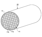
- FIG. 2 shows a honeycomb structure 10 as an example of the SCR catalyst 131.
- the honeycomb structure 10 includes a single honeycomb unit 11 that includes zeolite and an inorganic binder and has a plurality of through holes 11a arranged in parallel in the longitudinal direction with the partition walls 11b interposed therebetween. Further, the outer peripheral coat layer 12 is formed on the outer peripheral surface excluding both end surfaces of the honeycomb unit 11.
- the zeolite contained in the honeycomb unit 11 is not particularly limited, and examples thereof include ⁇ -type zeolite, ZSM-5-type zeolite, phosphate zeolite, and the like, and two or more kinds may be used in combination. Among them, phosphate zeolite is preferable because of its excellent NOx purification performance.
- phosphate zeolite examples include SAPO (silicoaluminophosphate) such as SAPO-5, SAPO-11, and SAPO-34; MeAPO (metalloaluminophosphate); MeAPSO (metal skeleton-substituted silicoaluminophosphate) and the like.
- SAPO sicoaluminophosphate
- MeAPO metaloaluminophosphate
- MeAPSO metal skeleton-substituted silicoaluminophosphate
- Zeolite is preferably ion-exchanged with copper ions and / or iron ions, more preferably ion-exchanged with copper ions in order to improve NOx purification performance.
- the zeolite ion-exchanged with copper ions and / or iron ions preferably has an ion exchange amount of 1.0 to 5.0% by mass.
- metal ions for ion-exchange of zeolite are not limited to copper ions and / or iron ions, and include transition metal ions that can improve NOx purification performance.
- the average particle diameter of the primary particles or secondary particles of the zeolite is preferably 0.5 to 10 ⁇ m, and more preferably 1 to 5 ⁇ m.
- the average particle diameter of the primary particles or secondary particles of the zeolite is less than 0.5 ⁇ m, the exhaust gas hardly enters the partition walls 11b of the honeycomb unit 11, and the zeolite is not effectively used for NOx purification.
- the average particle size of the primary particles or secondary particles of the zeolite exceeds 10 ⁇ m, the number of pores in the honeycomb unit 11 is reduced, so that the exhaust gas does not easily enter the partition walls 11b of the honeycomb unit 11. Is not effectively used for NOx purification.
- the honeycomb unit 11 preferably has a zeolite content of 230 to 400 g / L per apparent volume. If the zeolite content per apparent volume of the honeycomb unit 11 is less than 230 g / L, it is necessary to increase the apparent volume of the honeycomb unit 11 in order to improve the NOx purification performance. On the other hand, if the content of zeolite per apparent volume of the honeycomb unit 11 exceeds 400 g / L, the strength of the honeycomb unit 11 becomes insufficient or the aperture ratio of the honeycomb unit 11 becomes small.
- the inorganic binder contained in the honeycomb unit 11 is not particularly limited, and examples thereof include solids contained in alumina sol, silica sol, titania sol, water glass, sepiolite, attapulgite, boehmite and the like, and two or more kinds may be used in combination.
- the content of the inorganic binder in the honeycomb unit 11 is preferably 5 to 30% by mass, and more preferably 10 to 20% by mass.
- the content of the inorganic binder in the honeycomb unit 11 is less than 5% by mass, the strength of the honeycomb unit 11 is lowered.
- the content of the inorganic binder in the honeycomb unit 11 exceeds 30% by mass, it becomes difficult to extrude the honeycomb unit 11.
- the honeycomb unit 11 preferably further includes at least one selected from the group consisting of inorganic fibers, scale-like substances, tetrapot-like substances, and three-dimensional needle-like substances in order to improve the strength.
- the material constituting the inorganic fiber contained in the honeycomb unit 11 is not particularly limited, and examples thereof include alumina, silica, silicon carbide, silica alumina, glass, potassium titanate, and aluminum borate. Also good.
- the aspect ratio of the inorganic fibers contained in the honeycomb unit 11 is preferably 2 to 1000, more preferably 5 to 800, and even more preferably 10 to 500.
- the aspect ratio of the inorganic fibers contained in the honeycomb unit 11 is less than 2, the effect of improving the strength of the honeycomb unit 11 is reduced.
- the aspect ratio of the inorganic fibers contained in the honeycomb unit 11 exceeds 1000, the mold is clogged when the honeycomb unit 11 is extruded, or the inorganic fibers break and the strength of the honeycomb unit 11 is increased. The effect of improving the quality is reduced.
- the scaly substance means a flat substance, preferably having a thickness of 0.2 to 5.0 ⁇ m, preferably having a maximum length of 10 to 160 ⁇ m, and a ratio of the maximum length to the thickness of 3 It is preferable that it is -250.
- the material constituting the scaly substance contained in the honeycomb unit 11 is not particularly limited, and examples thereof include glass, muscovite, alumina, silica and the like, and two or more kinds may be used in combination.
- the tetrapot-like substance means a substance in which the needle-like portion extends three-dimensionally.
- the average needle-like length of the needle-like portion is preferably 5 to 30 ⁇ m, and the average diameter of the needle-like portion is 0.5. It is preferable that the thickness is ⁇ 5.0 ⁇ m.
- the three-dimensional acicular substance means a substance in which the acicular parts are bonded by an inorganic compound such as glass near the center of each acicular part, and the average acicular length of the acicular parts is 5 to 30 ⁇ m. It is preferable that the average diameter of the needle-shaped part is 0.5 to 5.0 ⁇ m.
- the three-dimensional acicular substance may have a plurality of acicular portions connected in three dimensions, and the diameter of the acicular portion is preferably 0.1 to 5 ⁇ m and the length is 0.3 to 30. It is preferably 0 ⁇ m, and the ratio of length to diameter is preferably 1.4 to 50.0.
- the material constituting the three-dimensional acicular substance contained in the honeycomb unit 11 is not particularly limited, and examples thereof include alumina, silica, silicon carbide, silica alumina, glass, potassium titanate, aluminum borate, boehmite, and the like. Two or more species may be used in combination.
- the content of inorganic fiber, scale-like substance, tetrapot-like substance and three-dimensional needle-like substance in the honeycomb unit 11 is preferably 3 to 50% by mass, more preferably 3 to 30% by mass. More preferred is mass%.
- the content of the inorganic fiber, scale-like substance, tetrapot-like substance and three-dimensional needle-like substance in the honeycomb unit 11 is less than 3% by mass, the effect of improving the strength of the honeycomb unit 11 becomes small.
- the honeycomb unit 11 preferably has a porosity of 20 to 50%.
- the porosity of the honeycomb unit 11 is less than 20%, the exhaust gas hardly enters the partition walls 11b of the honeycomb unit 11 and the zeolite is not effectively used for NOx purification.
- the porosity of the honeycomb unit 11 exceeds 50%, the strength of the honeycomb unit 11 becomes insufficient.
- the porosity of the honeycomb unit 11 can be measured using a mercury intrusion method.
- the honeycomb unit 11 preferably has an opening ratio of a cross section perpendicular to the longitudinal direction of 50 to 75%. If the opening ratio of the cross section perpendicular to the longitudinal direction of the honeycomb unit 11 is less than 50%, the zeolite is not effectively used for purification of NOx. On the other hand, if the opening ratio of the cross section perpendicular to the longitudinal direction of the honeycomb unit 11 exceeds 75%, the strength of the honeycomb unit 11 becomes insufficient.
- the density of the through holes 11a having a cross section perpendicular to the longitudinal direction is preferably 31 to 155 / cm 2 .
- the density of the through-holes 11a having a cross section perpendicular to the longitudinal direction of the honeycomb unit 11 is less than 31 / cm 2 , it becomes difficult for the exhaust gas and zeolite to come into contact with each other, and the NOx purification performance decreases.
- the density of the through holes 11a having a cross section perpendicular to the longitudinal direction of the honeycomb unit 11 exceeds 155 / cm 2 , the pressure loss of the honeycomb structure 10 increases.
- the thickness of the partition wall 11b of the honeycomb unit 11 is preferably 0.1 to 0.4 mm, and more preferably 0.1 to 0.3 mm.
- the thickness of the partition wall 11b of the honeycomb unit 11 is less than 0.1 mm, the strength of the honeycomb unit 11 decreases.
- the thickness of the partition wall 11b of the honeycomb unit 11 exceeds 0.4 mm, the exhaust gas hardly enters the partition wall 11b of the honeycomb unit 11, and the zeolite is not effectively used for NOx purification.
- the outer peripheral coat layer 12 preferably has a thickness of 0.1 to 2.0 mm.
- the thickness of the outer peripheral coat layer 12 is less than 0.1 mm, the effect of improving the strength of the honeycomb structure 10 becomes insufficient.
- the thickness of the outer peripheral coat layer 12 exceeds 2.0 mm, the content of zeolite per unit volume of the honeycomb structure 10 decreases, and the NOx purification performance decreases.
- the shape of the honeycomb structure 10 is not limited to a cylindrical shape, and examples thereof include a prismatic shape, an elliptical cylindrical shape, a long cylindrical shape, and a rounded chamfered prismatic shape (for example, a rounded chamfered triangular prism shape).
- the shape of the through hole 11a is not limited to a quadrangular prism shape, but may be a triangular prism shape, a hexagonal prism shape, or the like.
- honeycomb structure 10 Next, an example of a method for manufacturing the honeycomb structure 10 will be described. First, extrusion molding using a raw material paste containing a zeolite and an inorganic binder, and further containing at least one selected from the group consisting of inorganic fibers, scaly substances, tetrapot-like substances, and three-dimensional acicular substances, if necessary Then, a cylindrical honeycomb formed body in which a plurality of through holes are arranged in parallel in the longitudinal direction with a partition wall therebetween is manufactured.
- the inorganic binder contained in the raw material paste is not particularly limited, but is added as alumina sol, silica sol, titania sol, water glass, sepiolite, attapulgite, boehmite, etc., and two or more kinds may be used in combination.
- an organic binder, a dispersion medium, a molding aid and the like may be appropriately added to the raw material paste as necessary.
- the organic binder is not particularly limited, and examples thereof include methyl cellulose, carboxymethyl cellulose, hydroxyethyl cellulose, polyethylene glycol, phenol resin, and epoxy resin, and two or more kinds may be used in combination.
- the addition amount of the organic binder is preferably 1 to 10% based on the total mass of the zeolite, the inorganic binder, the inorganic fiber, the scale-like substance, the tetrapot-like substance, and the three-dimensional needle-like substance.
- the dispersion medium is not particularly limited, and examples thereof include water, organic solvents such as benzene, alcohols such as methanol, and the like.
- the molding aid is not particularly limited, and examples thereof include ethylene glycol, dextrin, fatty acid, fatty acid soap, polyalcohol and the like, and two or more kinds may be used in combination.
- the raw material paste it is preferable to mix and knead, and it may be mixed using a mixer, an attritor or the like, or may be kneaded using a kneader or the like.
- the honeycomb formed body is dried by using a dryer such as a microwave dryer, a hot air dryer, a dielectric dryer, a vacuum dryer, a vacuum dryer, a freeze dryer or the like to prepare a honeycomb dried body.
- a dryer such as a microwave dryer, a hot air dryer, a dielectric dryer, a vacuum dryer, a vacuum dryer, a freeze dryer or the like to prepare a honeycomb dried body.
- honeycomb dried body is degreased to produce a honeycomb degreased body.
- the degreasing conditions can be appropriately selected depending on the type and amount of the organic substance contained in the dried honeycomb body, but it is preferably 2 hours at 400 ° C.
- the honeycomb degreased body is fired to produce a cylindrical honeycomb unit 11.
- the firing temperature is preferably 600 to 1200 ° C, and more preferably 600 to 1000 ° C.
- the firing temperature is less than 600 ° C., the sintering does not proceed and the strength of the honeycomb unit 11 is lowered.
- the firing temperature exceeds 1200 ° C., the sintering proceeds too much and the reaction sites of the zeolite decrease.
- the outer peripheral coat layer paste is applied to the outer peripheral surface excluding both end surfaces of the cylindrical honeycomb unit 11.
- the inorganic binder contained in the outer periphery coating layer paste is not particularly limited, but is added as silica sol, alumina sol or the like, and two or more kinds may be used in combination. Among these, it is preferable to add as silica sol.
- the material constituting the inorganic particles contained in the outer peripheral coat layer paste is not particularly limited, but examples thereof include carbides such as silicon carbide, nitrides such as silicon nitride and boron nitride, and two or more kinds may be used in combination. . Of these, silicon carbide is preferred because of its excellent thermal conductivity.
- a silica alumina, a mullite, an alumina, a silica etc. are mentioned, You may use 2 or more types together. Of these, alumina is preferable.
- the outer periphery coating layer paste may further contain an organic binder.
- the outer peripheral coat layer paste may further contain balloons, pore formers, and the like, which are fine hollow spheres of oxide ceramics.
- the balloon contained in the outer periphery coating layer paste is not particularly limited, and examples thereof include alumina balloons, glass micro balloons, shirasu balloons, fly ash balloons, mullite balloons, and the like, and two or more kinds may be used in combination. Among these, an alumina balloon is preferable.
- a spherical acrylic particle, a graphite, etc. are mentioned, You may use 2 or more types together.
- a columnar honeycomb structure 10 is manufactured.
- the outer peripheral coat layer paste contains an organic binder, it is preferably degreased.
- the degreasing conditions can be appropriately selected depending on the kind and amount of the organic matter, but it is preferably 20 minutes at 700 ° C.
- zeolite may be ion-exchanged by immersing the honeycomb unit 11 or the honeycomb structure 10 in an aqueous solution containing copper ions and / or iron ions. Moreover, you may use the raw material paste containing the zeolite ion-exchanged with a copper ion and / or an iron ion.
- FIG. 3 shows a honeycomb structure 20 as another example of the SCR catalyst 131.
- the honeycomb structure 20 has a structure in which a plurality of honeycomb units 21 (see FIG. 4) in which a plurality of through holes 11 a are arranged in parallel in the longitudinal direction with a partition wall 11 b therebetween are bonded via an adhesive layer 22.
- the configuration is the same as that of the honeycomb structure 10.
- the honeycomb unit 21 preferably has a cross-sectional area of 10 to 200 cm 2 in a cross section perpendicular to the longitudinal direction.
- the cross-sectional area of the cross section perpendicular to the longitudinal direction of the honeycomb unit 21 is less than 10 cm 2 , the pressure loss of the honeycomb structure 20 increases.
- the cross-sectional area of the cross section perpendicular to the longitudinal direction of the honeycomb unit 21 exceeds 200 cm 2 , the strength against the thermal stress generated in the honeycomb unit 21 becomes insufficient.
- the honeycomb unit 21 has the same configuration as the honeycomb unit 11 except for the cross-sectional area of the cross section perpendicular to the longitudinal direction.
- the adhesive layer 22 preferably has a thickness of 0.5 to 2.0 mm.
- the thickness of the adhesive layer 22 is less than 0.5 mm, the adhesive strength of the honeycomb unit 21 becomes insufficient.
- the thickness of the adhesive layer 22 exceeds 2.0 mm, the pressure loss of the honeycomb structure 20 increases.
- honeycomb structure 20 First, in the same manner as the honeycomb structure 10, a quadrangular columnar honeycomb unit 21 is manufactured. Next, an adhesive layer paste is applied to the outer peripheral surface excluding both end faces of the honeycomb unit 21, the honeycomb units 21 are sequentially bonded, and dried and solidified, whereby the aggregate of the honeycomb units 21 is manufactured.
- the adhesive layer paste is not particularly limited, and examples thereof include a mixture of inorganic binder and inorganic particles, a mixture of inorganic binder and inorganic fibers, a mixture of inorganic binder, inorganic particles, and inorganic fibers.
- the inorganic binder contained in the adhesive layer paste is not particularly limited, but is added as silica sol, alumina sol or the like, and two or more kinds may be used in combination. Among these, it is preferable to add as silica sol.
- the material constituting the inorganic particles contained in the adhesive layer paste is not particularly limited, and examples thereof include carbides such as silicon carbide, nitrides such as silicon nitride and boron nitride, and two or more kinds may be used in combination. Of these, silicon carbide is preferred because of its excellent thermal conductivity.
- the material constituting the inorganic fibers contained in the adhesive layer paste is not particularly limited, and examples thereof include silica alumina, mullite, alumina, silica and the like, and two or more kinds may be used in combination. Of these, alumina is preferable.
- the adhesive layer paste may contain an organic binder.
- the organic binder contained in the adhesive layer paste is not particularly limited, and examples thereof include polyvinyl alcohol, methyl cellulose, ethyl cellulose, carboxymethyl cellulose and the like, and two or more kinds may be used in combination.
- the adhesive layer paste may further contain balloons that are fine hollow spheres of oxide ceramics, a pore-forming agent, and the like.
- the balloon contained in the adhesive layer paste is not particularly limited, and examples thereof include an alumina balloon, a glass microballoon, a shirasu balloon, a fly ash balloon, and a mullite balloon, and two or more kinds may be used in combination. Among these, an alumina balloon is preferable.
- the pore former contained in the adhesive layer paste is not particularly limited, and examples thereof include spherical acrylic particles and graphite, and two or more kinds may be used in combination.
- the aggregate of the honeycomb units 21 is cut into a cylindrical shape, and then polished as necessary to produce an aggregate of the cylindrical honeycomb units 21.
- the honeycomb unit 21 whose cross section perpendicular to the longitudinal direction is formed into a predetermined shape is bonded to the aggregate of the cylindrical honeycomb units 21. May be produced.
- the shape of the cross section perpendicular to the longitudinal direction of the honeycomb unit 21 is preferably a sector having a central angle of 90 °.
- the outer peripheral coat layer paste is applied to the outer peripheral surface excluding both end surfaces of the aggregate of the cylindrical honeycomb units 21.
- the outer periphery coat layer paste may be the same as or different from the adhesive layer paste.
- a columnar honeycomb structure 20 is manufactured by drying and solidifying the aggregate of columnar honeycomb units 21 to which the outer periphery coating layer paste is applied.
- an organic binder is contained in the adhesive layer paste and / or the outer peripheral coat layer paste, it is preferable to degrease.
- the degreasing conditions can be appropriately selected depending on the kind and amount of the organic matter, but it is preferably 20 minutes at 700 ° C.
- honeycomb structures 10 and 20 may not have the outer peripheral coat layer 12 formed thereon.
- honeycomb unit 11 or 21 a honeycomb structure having a honeycomb unit in which a plurality of through holes are arranged in parallel in the longitudinal direction with a partition wall therebetween and on which zeolite is supported may be used.
- the material constituting the honeycomb unit on which zeolite is supported is not particularly limited, and examples thereof include cordierite.
- the zeolite supported on the honeycomb unit is not particularly limited, and examples thereof include ⁇ -type zeolite, ZSM-5-type zeolite, and phosphate-based zeolite, and two or more kinds may be used in combination. Among them, phosphate zeolite is preferable because of its excellent NOx purification performance.
- phosphate zeolite examples include SAPO such as SAPO-5, SAPO-11, and SAPO-34; MeAPO; MeAPSO and the like.
- the zeolite is preferably ion-exchanged with copper ions and / or iron ions, and more preferably ion-exchanged with copper ions in consideration of NOx purification performance.
- the zeolite ion-exchanged with copper ions and / or iron ions preferably has an ion exchange amount of 1.0 to 5.0% by mass.
- metal ions for ion-exchange of zeolite are not limited to copper ions and / or iron ions, and include transition metal ions that can improve NOx purification performance.
- the exhaust gas purification method of the present invention is a method of purifying exhaust gas using the exhaust gas purification device of the present invention, detailed description thereof is omitted.
- a part means a mass part.
- DOC-1 A commercially available cordierite honeycomb structure carrying an oxidation catalyst was used.
- the honeycomb structure has a cylindrical shape with a diameter of 228.6 mm and a length of 114.3 mm.
- [DPF-1] 60 parts of ⁇ -type silicon carbide having an average particle diameter of 11 ⁇ m and 40 parts of ⁇ -type silicon carbide having an average particle diameter of 0.5 ⁇ m were mixed. Next, 5 parts of carboxymethyl cellulose and 10 parts of water were added and mixed and kneaded. Furthermore, a small amount of glycerin and a lubricant unilube (manufactured by NOF Corporation) were added and mixed and kneaded to prepare a raw material paste.
- the raw material paste was extruded using an extruder, and a cylindrical honeycomb formed body was produced. Then, the honeycomb formed body was dried using a microwave dryer and a hot air dryer, and a honeycomb dried body was manufactured.
- the raw material paste was filled into one end portion of the through hole of the dried honeycomb body.
- the honeycomb formed body was dried using a microwave dryer and a hot air dryer, and then degreased.
- the honeycomb unit was manufactured by firing at 2200 ° C. for 3 hours in an argon atmosphere.
- the honeycomb unit has a square prism shape with a side of 34.3 mm and a length of 203.2 mm, a density of through holes of 46.5 pieces / cm 2 , a partition wall thickness of 0.15 mm, and an average pore diameter of 11 ⁇ m.
- the porosity was 42%.
- the adhesive layer paste was applied to the outer peripheral surface excluding both ends of the honeycomb unit so that the adhesive layer had a thickness of 1.0 mm, and 36 honeycomb units were adhered and dried and solidified at 120 ° C.
- a diamond cutter was used to cut into a cylindrical shape so that the cross section perpendicular to the longitudinal direction was substantially point-symmetric, and a honeycomb unit aggregate was produced.
- silica alumina fiber having an average fiber diameter of 50 ⁇ m 30.2 parts of silicon carbide having an average particle diameter of 0.3 ⁇ m, 7 parts of silica sol having a solid content of 30% by mass, 0.5 part of carboxymethylcellulose, and 39 parts of water was mixed and kneaded to prepare a peripheral coat layer paste.
- An outer peripheral coating layer paste is applied to the outer peripheral surface excluding both ends of the aggregate of honeycomb units, and then dried and solidified at 120 ° C. to form a cylindrical honeycomb structure having a diameter of 228.6 mm and a length of 203.2 mm The body was made.
- the honeycomb structure has a cylindrical shape with a diameter of 228.6 mm and a length of 279.4 mm, and an outer peripheral coat layer with a thickness of 0.2 mm is formed on the outer peripheral surface excluding both ends of a single honeycomb unit. ing.
- the honeycomb unit has a density of through holes of 46.5 / cm 2 , a partition wall thickness of 0.30 mm, an average pore diameter of 15 ⁇ m, a porosity of 48%, and no catalyst is supported.
- the raw material paste was extruded using an extruder, and a cylindrical honeycomb formed body was produced. Then, the honeycomb formed body was dried at 110 ° C. for 10 minutes using a microwave dryer and a hot air dryer, and then degreased at 400 ° C. for 5 hours. Next, the honeycomb fired body was fired at 700 ° C. for 2 hours.
- the honeycomb structure 10 was manufactured by immersing the honeycomb structure in an aqueous copper nitrate solution to ion-exchange zeolite with copper ions.
- the ion exchange amount of the zeolite was measured by ICP emission analysis using ICPS-8100 (manufactured by Shimadzu Corporation), and it was 2.7% by mass.
- the honeycomb structure 10 has a cylindrical shape with a diameter of 228.6 mm and a length of 203.2 mm.
- the honeycomb unit 11 has a partition wall thickness of 0.28 mm and a through hole density of 62 holes / cm 2. It was.
- SCR catalyst-2 A cylindrical honeycomb structure having a diameter of 190.5 mm and a length of 292.1 mm was produced in the same manner as SCR catalyst-1.
- [SCR catalyst-3] A commercially available honeycomb structure made of cordierite was immersed in a dispersion of zeolite ion-exchanged by 2.7% by mass with copper ions to carry 170 g / L of zeolite.
- the honeycomb structure has a cylindrical shape with a diameter of 228.6 mm and a length of 304.8 mm, and an outer peripheral coat layer with a thickness of 0.2 mm is formed on the outer peripheral surface excluding both ends of a single honeycomb unit. ing.
- the honeycomb unit had a partition wall thickness of 0.28 mm and a through hole density of 62 holes / cm 2 .
- [SCR catalyst-4] A commercially available honeycomb structure made of cordierite was immersed in a dispersion of zeolite ion-exchanged by 2.7% by mass with copper ions to carry 170 g / L of zeolite.
- the honeycomb structure has a cylindrical shape having a diameter of 190.5 mm and a length of 439.4 mm, and an outer peripheral coat layer having a thickness of 0.2 mm is formed on the outer peripheral surface excluding both ends of a single honeycomb unit. ing.
- the honeycomb unit had a partition wall thickness of 0.28 mm and a through hole density of 62 holes / cm 2 .
- DOC-1, DPF-1, and SCR catalyst-2 are used as DOC111, DPF121, and SCR catalyst 131, respectively, so that the distance between DOC111 and DPF121 is 200 mm, and the distance between DPF121 and SCR catalyst 131 is 550 mm. It installed and produced the exhaust gas purification system 100 (refer FIG. 1). At this time, the injection nozzle was installed so that urea water was injected at a position where the distance from the DPF 121 was 200 mm.
- Example 2 Exhaust gas purification system 100 was produced in the same manner as in Example 1 except that DPF-2 was used as DPF 121.
- Example 3 Exhaust gas purification system 100 was produced in the same manner as in Example 1 except that SCR catalyst-4 was used as SCR catalyst 131.
- Example 1 An exhaust gas purification system was produced in the same manner as in Example 1 except that SCR catalyst-1 was used as the SCR catalyst 131 and the distance between the DPF 121 and the SCR catalyst 131 was set to 800 mm.
- Comparative Example 2 An exhaust gas purification system was produced in the same manner as in Comparative Example 1, except that the distance between the DPF 121 and the SCR catalyst 131 was set to 950 mm.
- Example 3 An exhaust gas purification system was produced in the same manner as in Example 2 except that SCR catalyst-1 was used as the SCR catalyst 131 and the distance between the DPF 121 and the SCR catalyst 131 was set to 950 mm.
- Example 4 An exhaust gas purification system was produced in the same manner as in Example 1 except that SCR catalyst-3 was used as the SCR catalyst 131 and the distance between the DPF 121 and the SCR catalyst 131 was set to 950 mm.
- the NOx purification rate is measured by installing NOx sensors upstream and downstream of the SCR catalyst 131 with respect to the direction of exhaust gas flow, and detecting the concentration of NOx in the exhaust gas for 30 minutes.
- (NOx inflow-NOx outflow) / (NOx inflow) x 100 [%] Is the average value of the values represented by At this time, steady operation was performed under the condition that the temperature of the exhaust gas was 250 ° C. Further, when the temperature of the SCR catalyst 131 is 180 ° C. or higher, the molar ratio of ammonia to NOx detected by the NOx sensor installed on the upstream side of the SCR catalyst 131 becomes 1 with respect to the flow direction of the exhaust gas.
- urea water was injected into the pipe 150 using an injection nozzle. Furthermore, urea water was diffused in the radial direction of the pipe 150 using a mixer and a swirler.
- Table 1 shows the measurement results of the length of the exhaust gas purification system and the NOx purification rate, together with the types of DOC, DPF and SCR catalyst.
- the cross-sectional area ratio of the SCR catalyst to the DPF means the ratio of the area of the cross section perpendicular to the longitudinal direction of the SCR catalyst to the area of the cross section perpendicular to the longitudinal direction of the DPF.
- the length of the exhaust gas purification system means the distance from the upstream end portion of the DOC 111 to the downstream end portion of the SCR catalyst 122 in the exhaust gas flow direction.
- Table 1 shows that the exhaust gas purification systems 100 of Examples 1 to 3 can make the length of the exhaust gas purification system 1360 to 1507 mm while maintaining the NOx purification rate at 73 to 86%.
- the length of the exhaust gas purification system is 1521 mm, but it can be seen that the NOx purification rate decreases to 47%.
Landscapes
- Engineering & Computer Science (AREA)
- Chemical & Material Sciences (AREA)
- Chemical Kinetics & Catalysis (AREA)
- Combustion & Propulsion (AREA)
- Mechanical Engineering (AREA)
- General Engineering & Computer Science (AREA)
- Ceramic Engineering (AREA)
- Health & Medical Sciences (AREA)
- Toxicology (AREA)
- Exhaust Gas After Treatment (AREA)
- Catalysts (AREA)
- Exhaust Gas Treatment By Means Of Catalyst (AREA)
Abstract
L'invention concerne un système d'épuration des gaz d'échappement comportant un catalyseur d'oxydation, un filtre, et un catalyseur de réduction catalytique sélective avec une tuyauterie entre eux dans l'ordre donné dans la direction d'écoulement des gaz d'échappement dans la voie de passage des gaz d'échappement d'un moteur diesel, et le système d'épuration des gaz d'échappement comportant un moyen d'alimentation d'ammoniac entre le filtre et le catalyseur de réduction catalytique sélective. Le filtre est une structure en nid d'abeilles ayant une unité en nid d'abeilles dans laquelle une pluralité de trous débouchants sont mis en œuvre de manière parallèle dans le sens de la longueur et séparés par des cloisons, une extrémité des trous débouchants étant fermée. Le catalyseur de réduction catalytique sélective est une structure en nid d'abeilles ayant une unité en nid d'abeilles dans laquelle une pluralité de trous débouchants sont mis en œuvre de manière parallèle dans le sens de la longueur et séparés par des cloisons. Le rapport entre la surface de la coupe transversale perpendiculaire au sens de la longueur du catalyseur de réduction catalytique sélective et la surface de la coupe transversale perpendiculaire au sens de la longueur du filtre est de 0,55 à 0,90 inclus, et la surface de la coupe transversale perpendiculaire au sens de la longueur du filtre est de 300 à 1000 cm2 inclus.
Priority Applications (3)
| Application Number | Priority Date | Filing Date | Title |
|---|---|---|---|
| PCT/JP2011/057856 WO2012131915A1 (fr) | 2011-03-29 | 2011-03-29 | Système d'épuration des gaz d'échappement and procédé d'épuration des gaz d'échappement |
| EP11187073.9A EP2505801A3 (fr) | 2011-03-29 | 2011-10-28 | Système et procédé de conversion de gaz d'échappement |
| US13/314,102 US8394347B2 (en) | 2011-03-29 | 2011-12-07 | Exhaust gas conversion system and exhaust gas conversion method |
Applications Claiming Priority (1)
| Application Number | Priority Date | Filing Date | Title |
|---|---|---|---|
| PCT/JP2011/057856 WO2012131915A1 (fr) | 2011-03-29 | 2011-03-29 | Système d'épuration des gaz d'échappement and procédé d'épuration des gaz d'échappement |
Publications (1)
| Publication Number | Publication Date |
|---|---|
| WO2012131915A1 true WO2012131915A1 (fr) | 2012-10-04 |
Family
ID=45002627
Family Applications (1)
| Application Number | Title | Priority Date | Filing Date |
|---|---|---|---|
| PCT/JP2011/057856 WO2012131915A1 (fr) | 2011-03-29 | 2011-03-29 | Système d'épuration des gaz d'échappement and procédé d'épuration des gaz d'échappement |
Country Status (3)
| Country | Link |
|---|---|
| US (1) | US8394347B2 (fr) |
| EP (1) | EP2505801A3 (fr) |
| WO (1) | WO2012131915A1 (fr) |
Families Citing this family (2)
| Publication number | Priority date | Publication date | Assignee | Title |
|---|---|---|---|---|
| BR112016009479B1 (pt) * | 2013-10-30 | 2022-03-22 | Johnson Matthey Public Limited Company | Catalisador de três vias, e, sistema de escape para motores de combustão interna |
| CN113294229B (zh) * | 2021-05-08 | 2022-10-18 | 亿元达(天津)机电科技有限公司 | 汽车节能环保净化器 |
Citations (3)
| Publication number | Priority date | Publication date | Assignee | Title |
|---|---|---|---|---|
| WO2009141898A1 (fr) * | 2008-05-20 | 2009-11-26 | イビデン株式会社 | Structure en nid d'abeille |
| JP2010227755A (ja) * | 2009-03-26 | 2010-10-14 | Ngk Insulators Ltd | セラミックハニカム構造体 |
| JP2011012643A (ja) * | 2009-07-03 | 2011-01-20 | Isuzu Motors Ltd | 尿素scr触媒の還元剤供給装置 |
Family Cites Families (7)
| Publication number | Priority date | Publication date | Assignee | Title |
|---|---|---|---|---|
| GB9802504D0 (en) * | 1998-02-06 | 1998-04-01 | Johnson Matthey Plc | Improvements in emission control |
| JP2000303826A (ja) | 1999-04-16 | 2000-10-31 | Isuzu Motors Ltd | ディーゼルエンジンの排ガス浄化装置 |
| DE102005027063A1 (de) * | 2005-06-11 | 2006-12-14 | Man Nutzfahrzeuge Ag | Vorrichtung und Verfahren zur Nachbehandlung sauerstoffhaltiger Abgase von Brennkraftmaschinen, insbesondere Fahrzeug-Dieselmotoren |
| JP4787817B2 (ja) * | 2007-12-27 | 2011-10-05 | 三菱ふそうトラック・バス株式会社 | エンジンの排気浄化装置 |
| WO2009141885A1 (fr) * | 2008-05-20 | 2009-11-26 | イビデン株式会社 | Structure en nid d'abeille |
| FR2938005A3 (fr) * | 2008-11-03 | 2010-05-07 | Renault Sas | Systeme et procede de traitement des emissions polluantes d'un moteur a allumage par compression |
| WO2011061841A1 (fr) * | 2009-11-19 | 2011-05-26 | イビデン株式会社 | Structure en nid d'abeille et appareil de purification des gaz d'échappement |
-
2011
- 2011-03-29 WO PCT/JP2011/057856 patent/WO2012131915A1/fr active Application Filing
- 2011-10-28 EP EP11187073.9A patent/EP2505801A3/fr not_active Withdrawn
- 2011-12-07 US US13/314,102 patent/US8394347B2/en active Active
Patent Citations (3)
| Publication number | Priority date | Publication date | Assignee | Title |
|---|---|---|---|---|
| WO2009141898A1 (fr) * | 2008-05-20 | 2009-11-26 | イビデン株式会社 | Structure en nid d'abeille |
| JP2010227755A (ja) * | 2009-03-26 | 2010-10-14 | Ngk Insulators Ltd | セラミックハニカム構造体 |
| JP2011012643A (ja) * | 2009-07-03 | 2011-01-20 | Isuzu Motors Ltd | 尿素scr触媒の還元剤供給装置 |
Also Published As
| Publication number | Publication date |
|---|---|
| EP2505801A3 (fr) | 2013-11-20 |
| EP2505801A2 (fr) | 2012-10-03 |
| US8394347B2 (en) | 2013-03-12 |
| US20120251419A1 (en) | 2012-10-04 |
Similar Documents
| Publication | Publication Date | Title |
|---|---|---|
| WO2011061841A1 (fr) | Structure en nid d'abeille et appareil de purification des gaz d'échappement | |
| US10610830B2 (en) | Honeycomb structure | |
| WO2011061836A1 (fr) | Structure en nid d'abeille et appareil de purification des gaz d'échappement | |
| JP5317959B2 (ja) | ハニカム構造体 | |
| JP5815220B2 (ja) | ハニカム構造体及び排ガス浄化装置 | |
| JP5560158B2 (ja) | ハニカム構造体及び排ガス浄化装置 | |
| EP2319604B1 (fr) | Filtre en nids d'abeilles | |
| WO2009141885A1 (fr) | Structure en nid d'abeille | |
| JP2011125849A (ja) | ハニカム構造体及び排ガス浄化装置 | |
| WO2009141898A1 (fr) | Structure en nid d'abeille | |
| WO2011061835A1 (fr) | Structure en nid d'abeille et appareil de purification des gaz d'échappement | |
| JP5746061B2 (ja) | ハニカム構造体及びハニカム構造体の製造方法 | |
| WO2011061839A1 (fr) | Structure en nid d'abeille et appareil de purification des gaz d'échappement | |
| JP2011098336A (ja) | ハニカムフィルタ | |
| JP2012215166A (ja) | 排ガス浄化システム及び排ガス浄化方法 | |
| JP4320702B2 (ja) | 排気ガス浄化装置 | |
| WO2012131913A1 (fr) | Système d'épuration des gaz d'échappement et procédé d'épuration des gaz d'échappement | |
| JP7062493B2 (ja) | 触媒担持用ハニカム構造体及びその製造方法 | |
| JP2010279849A (ja) | ハニカム構造体 | |
| WO2013024548A1 (fr) | Structure en nid d'abeilles, son procédé de fabrication, dispositif de purification de gaz d'échappement et particules de silicoaluminophosphate | |
| WO2013024545A1 (fr) | Particule composite, structure en nid d'abeilles, procédé de fabrication de cette structure et dispositif de purification de gaz d'échappement | |
| WO2012131915A1 (fr) | Système d'épuration des gaz d'échappement and procédé d'épuration des gaz d'échappement | |
| JP5563952B2 (ja) | ハニカム構造体及び排ガス浄化装置 | |
| JP2012215167A (ja) | 排ガス浄化システム及び排ガス浄化方法 | |
| US8685331B2 (en) | Honeycomb structural body and exhaust gas conversion apparatus |
Legal Events
| Date | Code | Title | Description |
|---|---|---|---|
| 121 | Ep: the epo has been informed by wipo that ep was designated in this application |
Ref document number: 11862123 Country of ref document: EP Kind code of ref document: A1 |
|
| NENP | Non-entry into the national phase |
Ref country code: DE |
|
| 122 | Ep: pct application non-entry in european phase |
Ref document number: 11862123 Country of ref document: EP Kind code of ref document: A1 |