WO2012131913A1 - Exhaust gas purification system and exhaust gas purification method - Google Patents
Exhaust gas purification system and exhaust gas purification method Download PDFInfo
- Publication number
- WO2012131913A1 WO2012131913A1 PCT/JP2011/057854 JP2011057854W WO2012131913A1 WO 2012131913 A1 WO2012131913 A1 WO 2012131913A1 JP 2011057854 W JP2011057854 W JP 2011057854W WO 2012131913 A1 WO2012131913 A1 WO 2012131913A1
- Authority
- WO
- WIPO (PCT)
- Prior art keywords
- exhaust gas
- gas purification
- honeycomb unit
- purification system
- honeycomb
- Prior art date
Links
Images

Classifications
-
- F—MECHANICAL ENGINEERING; LIGHTING; HEATING; WEAPONS; BLASTING
- F01—MACHINES OR ENGINES IN GENERAL; ENGINE PLANTS IN GENERAL; STEAM ENGINES
- F01N—GAS-FLOW SILENCERS OR EXHAUST APPARATUS FOR MACHINES OR ENGINES IN GENERAL; GAS-FLOW SILENCERS OR EXHAUST APPARATUS FOR INTERNAL COMBUSTION ENGINES
- F01N3/00—Exhaust or silencing apparatus having means for purifying, rendering innocuous, or otherwise treating exhaust
- F01N3/08—Exhaust or silencing apparatus having means for purifying, rendering innocuous, or otherwise treating exhaust for rendering innocuous
- F01N3/10—Exhaust or silencing apparatus having means for purifying, rendering innocuous, or otherwise treating exhaust for rendering innocuous by thermal or catalytic conversion of noxious components of exhaust
- F01N3/18—Exhaust or silencing apparatus having means for purifying, rendering innocuous, or otherwise treating exhaust for rendering innocuous by thermal or catalytic conversion of noxious components of exhaust characterised by methods of operation; Control
- F01N3/20—Exhaust or silencing apparatus having means for purifying, rendering innocuous, or otherwise treating exhaust for rendering innocuous by thermal or catalytic conversion of noxious components of exhaust characterised by methods of operation; Control specially adapted for catalytic conversion ; Methods of operation or control of catalytic converters
- F01N3/2066—Selective catalytic reduction [SCR]
-
- F—MECHANICAL ENGINEERING; LIGHTING; HEATING; WEAPONS; BLASTING
- F01—MACHINES OR ENGINES IN GENERAL; ENGINE PLANTS IN GENERAL; STEAM ENGINES
- F01N—GAS-FLOW SILENCERS OR EXHAUST APPARATUS FOR MACHINES OR ENGINES IN GENERAL; GAS-FLOW SILENCERS OR EXHAUST APPARATUS FOR INTERNAL COMBUSTION ENGINES
- F01N13/00—Exhaust or silencing apparatus characterised by constructional features ; Exhaust or silencing apparatus, or parts thereof, having pertinent characteristics not provided for in, or of interest apart from, groups F01N1/00 - F01N5/00, F01N9/00, F01N11/00
- F01N13/009—Exhaust or silencing apparatus characterised by constructional features ; Exhaust or silencing apparatus, or parts thereof, having pertinent characteristics not provided for in, or of interest apart from, groups F01N1/00 - F01N5/00, F01N9/00, F01N11/00 having two or more separate purifying devices arranged in series
- F01N13/0097—Exhaust or silencing apparatus characterised by constructional features ; Exhaust or silencing apparatus, or parts thereof, having pertinent characteristics not provided for in, or of interest apart from, groups F01N1/00 - F01N5/00, F01N9/00, F01N11/00 having two or more separate purifying devices arranged in series the purifying devices are arranged in a single housing
-
- F—MECHANICAL ENGINEERING; LIGHTING; HEATING; WEAPONS; BLASTING
- F01—MACHINES OR ENGINES IN GENERAL; ENGINE PLANTS IN GENERAL; STEAM ENGINES
- F01N—GAS-FLOW SILENCERS OR EXHAUST APPARATUS FOR MACHINES OR ENGINES IN GENERAL; GAS-FLOW SILENCERS OR EXHAUST APPARATUS FOR INTERNAL COMBUSTION ENGINES
- F01N3/00—Exhaust or silencing apparatus having means for purifying, rendering innocuous, or otherwise treating exhaust
- F01N3/02—Exhaust or silencing apparatus having means for purifying, rendering innocuous, or otherwise treating exhaust for cooling, or for removing solid constituents of, exhaust
- F01N3/021—Exhaust or silencing apparatus having means for purifying, rendering innocuous, or otherwise treating exhaust for cooling, or for removing solid constituents of, exhaust by means of filters
- F01N3/022—Exhaust or silencing apparatus having means for purifying, rendering innocuous, or otherwise treating exhaust for cooling, or for removing solid constituents of, exhaust by means of filters characterised by specially adapted filtering structure, e.g. honeycomb, mesh or fibrous
- F01N3/0222—Exhaust or silencing apparatus having means for purifying, rendering innocuous, or otherwise treating exhaust for cooling, or for removing solid constituents of, exhaust by means of filters characterised by specially adapted filtering structure, e.g. honeycomb, mesh or fibrous the structure being monolithic, e.g. honeycombs
-
- F—MECHANICAL ENGINEERING; LIGHTING; HEATING; WEAPONS; BLASTING
- F01—MACHINES OR ENGINES IN GENERAL; ENGINE PLANTS IN GENERAL; STEAM ENGINES
- F01N—GAS-FLOW SILENCERS OR EXHAUST APPARATUS FOR MACHINES OR ENGINES IN GENERAL; GAS-FLOW SILENCERS OR EXHAUST APPARATUS FOR INTERNAL COMBUSTION ENGINES
- F01N3/00—Exhaust or silencing apparatus having means for purifying, rendering innocuous, or otherwise treating exhaust
- F01N3/02—Exhaust or silencing apparatus having means for purifying, rendering innocuous, or otherwise treating exhaust for cooling, or for removing solid constituents of, exhaust
- F01N3/021—Exhaust or silencing apparatus having means for purifying, rendering innocuous, or otherwise treating exhaust for cooling, or for removing solid constituents of, exhaust by means of filters
- F01N3/033—Exhaust or silencing apparatus having means for purifying, rendering innocuous, or otherwise treating exhaust for cooling, or for removing solid constituents of, exhaust by means of filters in combination with other devices
- F01N3/035—Exhaust or silencing apparatus having means for purifying, rendering innocuous, or otherwise treating exhaust for cooling, or for removing solid constituents of, exhaust by means of filters in combination with other devices with catalytic reactors, e.g. catalysed diesel particulate filters
-
- F—MECHANICAL ENGINEERING; LIGHTING; HEATING; WEAPONS; BLASTING
- F01—MACHINES OR ENGINES IN GENERAL; ENGINE PLANTS IN GENERAL; STEAM ENGINES
- F01N—GAS-FLOW SILENCERS OR EXHAUST APPARATUS FOR MACHINES OR ENGINES IN GENERAL; GAS-FLOW SILENCERS OR EXHAUST APPARATUS FOR INTERNAL COMBUSTION ENGINES
- F01N3/00—Exhaust or silencing apparatus having means for purifying, rendering innocuous, or otherwise treating exhaust
- F01N3/08—Exhaust or silencing apparatus having means for purifying, rendering innocuous, or otherwise treating exhaust for rendering innocuous
- F01N3/10—Exhaust or silencing apparatus having means for purifying, rendering innocuous, or otherwise treating exhaust for rendering innocuous by thermal or catalytic conversion of noxious components of exhaust
- F01N3/24—Exhaust or silencing apparatus having means for purifying, rendering innocuous, or otherwise treating exhaust for rendering innocuous by thermal or catalytic conversion of noxious components of exhaust characterised by constructional aspects of converting apparatus
- F01N3/28—Construction of catalytic reactors
- F01N3/2803—Construction of catalytic reactors characterised by structure, by material or by manufacturing of catalyst support
- F01N3/2825—Ceramics
- F01N3/2828—Ceramic multi-channel monoliths, e.g. honeycombs
-
- F—MECHANICAL ENGINEERING; LIGHTING; HEATING; WEAPONS; BLASTING
- F01—MACHINES OR ENGINES IN GENERAL; ENGINE PLANTS IN GENERAL; STEAM ENGINES
- F01N—GAS-FLOW SILENCERS OR EXHAUST APPARATUS FOR MACHINES OR ENGINES IN GENERAL; GAS-FLOW SILENCERS OR EXHAUST APPARATUS FOR INTERNAL COMBUSTION ENGINES
- F01N2330/00—Structure of catalyst support or particle filter
- F01N2330/30—Honeycomb supports characterised by their structural details
-
- F—MECHANICAL ENGINEERING; LIGHTING; HEATING; WEAPONS; BLASTING
- F01—MACHINES OR ENGINES IN GENERAL; ENGINE PLANTS IN GENERAL; STEAM ENGINES
- F01N—GAS-FLOW SILENCERS OR EXHAUST APPARATUS FOR MACHINES OR ENGINES IN GENERAL; GAS-FLOW SILENCERS OR EXHAUST APPARATUS FOR INTERNAL COMBUSTION ENGINES
- F01N2370/00—Selection of materials for exhaust purification
- F01N2370/02—Selection of materials for exhaust purification used in catalytic reactors
- F01N2370/04—Zeolitic material
-
- F—MECHANICAL ENGINEERING; LIGHTING; HEATING; WEAPONS; BLASTING
- F01—MACHINES OR ENGINES IN GENERAL; ENGINE PLANTS IN GENERAL; STEAM ENGINES
- F01N—GAS-FLOW SILENCERS OR EXHAUST APPARATUS FOR MACHINES OR ENGINES IN GENERAL; GAS-FLOW SILENCERS OR EXHAUST APPARATUS FOR INTERNAL COMBUSTION ENGINES
- F01N2430/00—Influencing exhaust purification, e.g. starting of catalytic reaction, filter regeneration, or the like, by controlling engine operating characteristics
-
- F—MECHANICAL ENGINEERING; LIGHTING; HEATING; WEAPONS; BLASTING
- F01—MACHINES OR ENGINES IN GENERAL; ENGINE PLANTS IN GENERAL; STEAM ENGINES
- F01N—GAS-FLOW SILENCERS OR EXHAUST APPARATUS FOR MACHINES OR ENGINES IN GENERAL; GAS-FLOW SILENCERS OR EXHAUST APPARATUS FOR INTERNAL COMBUSTION ENGINES
- F01N2450/00—Methods or apparatus for fitting, inserting or repairing different elements
- F01N2450/28—Methods or apparatus for fitting, inserting or repairing different elements by using adhesive material, e.g. cement
-
- F—MECHANICAL ENGINEERING; LIGHTING; HEATING; WEAPONS; BLASTING
- F01—MACHINES OR ENGINES IN GENERAL; ENGINE PLANTS IN GENERAL; STEAM ENGINES
- F01N—GAS-FLOW SILENCERS OR EXHAUST APPARATUS FOR MACHINES OR ENGINES IN GENERAL; GAS-FLOW SILENCERS OR EXHAUST APPARATUS FOR INTERNAL COMBUSTION ENGINES
- F01N2610/00—Adding substances to exhaust gases
- F01N2610/02—Adding substances to exhaust gases the substance being ammonia or urea
-
- Y—GENERAL TAGGING OF NEW TECHNOLOGICAL DEVELOPMENTS; GENERAL TAGGING OF CROSS-SECTIONAL TECHNOLOGIES SPANNING OVER SEVERAL SECTIONS OF THE IPC; TECHNICAL SUBJECTS COVERED BY FORMER USPC CROSS-REFERENCE ART COLLECTIONS [XRACs] AND DIGESTS
- Y02—TECHNOLOGIES OR APPLICATIONS FOR MITIGATION OR ADAPTATION AGAINST CLIMATE CHANGE
- Y02T—CLIMATE CHANGE MITIGATION TECHNOLOGIES RELATED TO TRANSPORTATION
- Y02T10/00—Road transport of goods or passengers
- Y02T10/10—Internal combustion engine [ICE] based vehicles
- Y02T10/12—Improving ICE efficiencies
Definitions
- the present invention relates to an exhaust gas purification system and an exhaust gas purification method.
- an SCR Selective Catalytic Reduction system that uses ammonia to reduce NOx to nitrogen and water has been known as one of systems for purifying automobile exhaust gas.
- zeolite is known as a material that adsorbs ammonia in the SCR system.
- an SCR catalyst for reducing and purifying NOx is disposed in an exhaust passage of a diesel engine, and a DOC (oxidation catalyst) and a DPF (filter) are connected in series from the upstream side to the upstream side of the SCR catalyst.
- an exhaust gas purification device in which a device for supplying and injecting a reducing agent is disposed in an exhaust passage between the DPF and the SCR catalyst.
- the present invention provides an exhaust gas purification system capable of reducing the arrangement space of the exhaust gas purification device while maintaining the NOx purification performance, and an exhaust gas purification method using the exhaust gas purification system.
- the purpose is to provide.
- an oxidation catalyst, a filter, and a selective catalyst reduction catalyst are sequentially provided in the exhaust gas flow direction of the exhaust path of the diesel engine, and ammonia is introduced between the oxidation catalyst and the filter.
- Means for supplying is provided.
- the filter is preferably a honeycomb structure having a honeycomb unit in which a plurality of through holes are arranged in parallel in the longitudinal direction with a partition wall therebetween and one end of the through hole is sealed.
- the filter does not carry a catalyst.
- the honeycomb unit preferably includes silicon carbide.
- the honeycomb unit preferably has a partition wall thickness of 0.10 mm to 0.18 mm.
- the selective catalyst reduction catalyst is a honeycomb structure having a honeycomb unit in which a plurality of through holes are arranged in parallel in the longitudinal direction with a partition wall therebetween, and the honeycomb unit preferably contains a zeolite and an inorganic binder.
- the honeycomb unit included in the selective catalyst reduction catalyst preferably further includes one or more selected from the group consisting of inorganic fibers, scale-like substances, tetrapot-like substances, and three-dimensional needle-like substances.
- the zeolite is preferably a phosphate-based zeolite.
- the filter and the selective catalytic reduction catalyst are preferably provided in a single metal container.
- the exhaust gas purification method of the present invention purifies exhaust gas using the exhaust gas purification system of the present invention.
- an exhaust gas purification system capable of reducing the arrangement space of the exhaust gas purification device while maintaining NOx purification performance, and an exhaust gas purification method using the exhaust gas purification system.
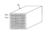
- FIG. 4 is a perspective view showing a honeycomb unit constituting the SCR catalyst of FIG. 3. It is a figure which shows the other example of the exhaust gas purification system of this invention.
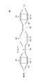
- FIG. 1 shows an example of the exhaust gas purification system of the present invention.
- exhaust gas purification devices 110, 120 and 130 are connected via pipes 140 and 150.
- the exhaust gas purification device 110 can be manufactured by canning the metal container (shell) 113 in a state where the holding sealing material 112 is disposed on the outer periphery of the DOC (oxidation catalyst) 111.
- the exhaust gas purifying device 120 can be manufactured by performing canning on the metal container 123 in a state where the holding sealing material 122 is disposed on the outer peripheral portion of the DPF (filter) 121.
- the exhaust gas purifying device 130 can be manufactured by performing canning on the metal container 133 in a state where the holding sealing material 132 is disposed on the outer peripheral portion of the SCR (selective catalyst reduction) catalyst 131. For this reason, the exhaust gas purification system 100 can purify the exhaust gas of the diesel engine.
- means for supplying ammonia such as an injection nozzle for injecting ammonia or a compound that decomposes to generate ammonia into the pipe 140 between the exhaust gas purification device 110 and the exhaust gas purification device 120). (Shown) is provided. As a result, ammonia is supplied into the pipe 140, so that the SCR catalyst 131 reduces NOx contained in the exhaust gas.
- the compound that decomposes to generate ammonia is not particularly limited as long as it can be heated by exhaust gas in the pipe 140 and generate ammonia, but urea water is preferable because of excellent storage stability.
- the urea water is heated by the exhaust gas in the pipe 140 and hydrolyzed to generate ammonia.
- the piping 150 may be omitted and the exhaust gas purification device 120 and the exhaust gas purification device 130 may be directly connected.
- the DOC 111 is a honeycomb structure having a honeycomb unit in which a plurality of through holes are arranged in parallel in the longitudinal direction with a partition wall therebetween and a catalyst is supported.
- a catalyst supporting layer for supporting a catalyst may be formed.
- the holding sealing materials 112, 122 and 132 are not particularly limited, but a mat containing inorganic fibers is preferable.
- the DPF 121 is a honeycomb structure having a honeycomb unit in which a plurality of through holes are arranged in parallel in the longitudinal direction with a partition wall therebetween and one end of the through hole is sealed.
- the material constituting the honeycomb unit included in the DPF 121 is not particularly limited, and examples thereof include silicon carbide (SiC), silicon-bonded silicon carbide (SiSiC), cordierite, aluminum titanate, and the like. Silicon carbide (SiC) or silicon-bonded silicon carbide (SiSiC) is preferred because cracks are unlikely to occur even when burned in large quantities.
- the honeycomb unit included in the DPF 121 does not carry a catalyst such as platinum, palladium, or rhodium. Thereby, oxidation of ammonia supplied into the pipe 140 can be suppressed. In addition, since the DPF 121 having a honeycomb unit on which no catalyst is supported does not rise in temperature due to the catalytic reaction, the strength of the honeycomb unit can be maintained even if the partition wall thickness of the honeycomb unit is reduced. *
- the honeycomb unit included in the DPF 121 preferably has a partition wall thickness of 0.10 to 0.18 mm.
- the thickness of the partition wall of the honeycomb unit included in the DPF 121 is less than 0.10 mm, the strength of the DPF 121 is reduced.
- the thickness of the partition wall of the honeycomb unit included in the DPF 121 exceeds 0.18 mm, the pressure loss of the DPF 121 increases, so that the arrangement space of the exhaust gas purification device 120 cannot be reduced.
- the SCR catalyst 131 is a honeycomb structure having a honeycomb unit in which a plurality of through holes are arranged in parallel in the longitudinal direction with a partition wall therebetween.
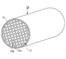
- FIG. 2 shows a honeycomb structure 10 as an example of the SCR catalyst 131.
- the honeycomb structure 10 includes a single honeycomb unit 11 that includes zeolite and an inorganic binder and has a plurality of through holes 11a arranged in parallel in the longitudinal direction with the partition walls 11b interposed therebetween. Further, the outer peripheral coat layer 12 is formed on the outer peripheral surface excluding both end surfaces of the honeycomb unit 11.
- the zeolite contained in the honeycomb unit 11 is not particularly limited, and examples thereof include ⁇ -type zeolite, ZSM-5-type zeolite, phosphate zeolite, and the like, and two or more kinds may be used in combination. Among them, phosphate zeolite is preferable because of its excellent NOx purification performance.
- phosphate zeolite examples include SAPO (silicoaluminophosphate) such as SAPO-5, SAPO-11, and SAPO-34; MeAPO (metalloaluminophosphate); MeAPSO (metal skeleton-substituted silicoaluminophosphate) and the like.
- SAPO sicoaluminophosphate
- MeAPO metaloaluminophosphate
- MeAPSO metal skeleton-substituted silicoaluminophosphate
- Zeolite is preferably ion-exchanged with copper ions and / or iron ions, more preferably ion-exchanged with copper ions in order to improve NOx purification performance.
- the zeolite ion-exchanged with copper ions and / or iron ions preferably has an ion exchange amount of 1.0 to 5.0% by mass.
- metal ions for ion-exchange of zeolite are not limited to copper ions and / or iron ions, and include transition metal ions that can improve NOx purification performance.
- the average particle diameter of the primary particles or secondary particles of the zeolite is preferably 0.5 to 10 ⁇ m, and more preferably 1 to 5 ⁇ m.
- the average particle diameter of the primary particles or secondary particles of the zeolite is less than 0.5 ⁇ m, the exhaust gas hardly enters the partition walls 11b of the honeycomb unit 11, and the zeolite is not effectively used for NOx purification.
- the average particle size of the primary particles or secondary particles of the zeolite exceeds 10 ⁇ m, the number of pores in the honeycomb unit 11 is reduced, so that the exhaust gas does not easily enter the partition walls 11b of the honeycomb unit 11. Is not effectively used for NOx purification.
- the honeycomb unit 11 preferably has a zeolite content of 230 to 400 g / L per apparent volume. If the zeolite content per apparent volume of the honeycomb unit 11 is less than 230 g / L, it is necessary to increase the apparent volume of the honeycomb unit 11 in order to improve the NOx purification performance. On the other hand, if the content of zeolite per apparent volume of the honeycomb unit 11 exceeds 400 g / L, the strength of the honeycomb unit 11 becomes insufficient or the aperture ratio of the honeycomb unit 11 becomes small.
- the inorganic binder contained in the honeycomb unit 11 is not particularly limited, and examples thereof include solids contained in alumina sol, silica sol, titania sol, water glass, sepiolite, attapulgite, boehmite and the like, and two or more kinds may be used in combination.
- the content of the inorganic binder in the honeycomb unit 11 is preferably 5 to 30% by mass, and more preferably 10 to 20% by mass.
- the content of the inorganic binder in the honeycomb unit 11 is less than 5% by mass, the strength of the honeycomb unit 11 is lowered.
- the content of the inorganic binder in the honeycomb unit 11 exceeds 30% by mass, the extrusion molding of the honeycomb unit 11 becomes difficult.
- the honeycomb unit 11 preferably further includes at least one selected from the group consisting of inorganic fibers, scale-like substances, tetrapot-like substances, and three-dimensional needle-like substances in order to improve the strength.
- the material constituting the inorganic fiber contained in the honeycomb unit 11 is not particularly limited, and examples thereof include alumina, silica, silicon carbide, silica alumina, glass, potassium titanate, and aluminum borate. Also good.
- the aspect ratio of the inorganic fibers contained in the honeycomb unit 11 is preferably 2 to 1000, more preferably 5 to 800, and even more preferably 10 to 500.
- the aspect ratio of the inorganic fibers contained in the honeycomb unit 11 is less than 2, the effect of improving the strength of the honeycomb unit 11 is reduced.
- the aspect ratio of the inorganic fibers contained in the honeycomb unit 11 exceeds 1000, the mold is clogged when the honeycomb unit 11 is extruded, or the inorganic fibers break and the strength of the honeycomb unit 11 is increased. The effect of improving the quality is reduced.
- the scaly substance means a flat substance, preferably having a thickness of 0.2 to 5.0 ⁇ m, preferably having a maximum length of 10 to 160 ⁇ m, and a ratio of the maximum length to the thickness of 3 It is preferable that it is -250.
- the material constituting the scaly substance contained in the honeycomb unit 11 is not particularly limited, and examples thereof include glass, muscovite, alumina, silica and the like, and two or more kinds may be used in combination.
- the tetrapot-like substance means a substance in which the needle-like portion extends three-dimensionally.
- the average needle-like length of the needle-like portion is preferably 5 to 30 ⁇ m, and the average diameter of the needle-like portion is 0.5. It is preferable that the thickness is ⁇ 5.0 ⁇ m.
- the three-dimensional acicular substance means a substance in which the acicular parts are bonded by an inorganic compound such as glass near the center of each acicular part, and the average acicular length of the acicular parts is 5 to 30 ⁇ m. It is preferable that the average diameter of the needle-shaped part is 0.5 to 5.0 ⁇ m.
- the three-dimensional acicular substance may have a plurality of acicular portions that are three-dimensionally connected, and preferably has a needle-like diameter of 0.1 to 5.0 ⁇ m and a length of 0.3 to It is preferably 30.0 ⁇ m, and the ratio of length to diameter is preferably 1.4 to 50.0.
- the material constituting the three-dimensional acicular substance contained in the honeycomb unit 11 is not particularly limited, and examples thereof include alumina, silica, silicon carbide, silica alumina, glass, potassium titanate, aluminum borate, boehmite, and the like. Two or more species may be used in combination.
- the content of inorganic fiber, scale-like substance, tetrapot-like substance and three-dimensional needle-like substance in the honeycomb unit 11 is preferably 3 to 50% by mass, more preferably 3 to 30% by mass. More preferred is mass%.
- the content of the inorganic fiber, scale-like substance, tetrapot-like substance and three-dimensional needle-like substance in the honeycomb unit 11 is less than 3% by mass, the effect of improving the strength of the honeycomb unit 11 becomes small.
- the honeycomb unit 11 preferably has a porosity of 20 to 50%.
- the porosity of the honeycomb unit 11 is less than 20%, the exhaust gas hardly enters the partition walls 11b of the honeycomb unit 11 and the zeolite is not effectively used for NOx purification.
- the porosity of the honeycomb unit 11 exceeds 50%, the strength of the honeycomb unit 11 becomes insufficient.
- the porosity of the honeycomb unit 11 can be measured using a mercury intrusion method.
- the honeycomb unit 11 preferably has an opening ratio of 50 to 75%. If the aperture ratio of the honeycomb unit 11 is less than 50%, the zeolite is not effectively used for NOx purification. On the other hand, when the aperture ratio of the honeycomb unit 11 exceeds 75%, the strength of the honeycomb unit 11 becomes insufficient.
- the density of the through holes 11a is preferably 31 to 155 / cm 2 .
- the density of the through holes 11a of the honeycomb unit 11 is less than 31 / cm 2 , the exhaust gas and the zeolite are difficult to contact with each other, and the NOx purification performance is lowered.
- the density of the through holes 11a of the honeycomb unit 11 exceeds 155 / cm 2 , the pressure loss of the honeycomb structure 10 increases.
- the thickness of the partition wall 11b of the honeycomb unit 11 is preferably 0.1 to 0.4 mm, and more preferably 0.1 to 0.3 mm.
- the thickness of the partition wall 11b of the honeycomb unit 11 is less than 0.1 mm, the strength of the honeycomb unit 11 decreases.
- the thickness of the partition wall 11b of the honeycomb unit 11 exceeds 0.4 mm, the exhaust gas hardly enters the partition wall 11b of the honeycomb unit 11, and the zeolite is not effectively used for NOx purification.
- the outer peripheral coat layer 12 preferably has a thickness of 0.1 to 2.0 mm.
- the thickness of the outer peripheral coat layer 12 is less than 0.1 mm, the effect of improving the strength of the honeycomb structure 10 becomes insufficient.
- the thickness of the outer peripheral coat layer 12 exceeds 2.0 mm, the content of zeolite per unit volume of the honeycomb structure 10 decreases, and the NOx purification performance decreases.
- the shape of the honeycomb structure 10 is not limited to a cylindrical shape, and examples thereof include a prismatic shape, an elliptical cylindrical shape, a long cylindrical shape, and a rounded chamfered prismatic shape (for example, a rounded chamfered triangular prism shape).
- the shape of the through hole 11a is not limited to a quadrangular prism shape, but may be a triangular prism shape, a hexagonal prism shape, or the like.
- honeycomb structure 10 Next, an example of a method for manufacturing the honeycomb structure 10 will be described. First, extrusion molding using a raw material paste containing a zeolite and an inorganic binder, and further containing at least one selected from the group consisting of inorganic fibers, scaly substances, tetrapot-like substances, and three-dimensional acicular substances, if necessary Then, a cylindrical honeycomb formed body in which a plurality of through holes are arranged in parallel in the longitudinal direction with a partition wall therebetween is manufactured.
- the inorganic binder contained in the raw material paste is not particularly limited, but is added as alumina sol, silica sol, titania sol, water glass, sepiolite, attapulgite, boehmite, etc., and two or more kinds may be used in combination.
- an organic binder, a dispersion medium, a molding aid and the like may be appropriately added to the raw material paste as necessary.
- the organic binder is not particularly limited, and examples thereof include methyl cellulose, carboxymethyl cellulose, hydroxyethyl cellulose, polyethylene glycol, phenol resin, and epoxy resin, and two or more kinds may be used in combination.
- the addition amount of the organic binder is preferably 1 to 10% with respect to the total mass of zeolite, inorganic binder, inorganic fiber, scaly substance, tetrapot-like substance, and three-dimensional acicular substance.
- the dispersion medium is not particularly limited, and examples thereof include water, organic solvents such as benzene, alcohols such as methanol, and the like.
- the molding aid is not particularly limited, and examples thereof include ethylene glycol, dextrin, fatty acid, fatty acid soap, polyalcohol and the like, and two or more kinds may be used in combination.
- the raw material paste it is preferable to mix and knead, and it may be mixed using a mixer, an attritor or the like, or may be kneaded using a kneader or the like.
- a honeycomb dried body is manufactured using a dryer such as a microwave dryer, a hot air dryer, a dielectric dryer, a vacuum dryer, a vacuum dryer, or a freeze dryer.
- a dryer such as a microwave dryer, a hot air dryer, a dielectric dryer, a vacuum dryer, a vacuum dryer, or a freeze dryer.
- honeycomb dried body is degreased to produce a honeycomb degreased body.
- the degreasing conditions can be appropriately selected depending on the type and amount of the organic substance contained in the dried honeycomb body, but it is preferably 2 hours at 400 ° C.
- the honeycomb degreased body is fired to produce a cylindrical honeycomb unit 11.
- the firing temperature is preferably 600 to 1200 ° C, and more preferably 600 to 1000 ° C.
- the firing temperature is less than 600 ° C., the sintering does not proceed and the strength of the honeycomb unit 11 is lowered.
- the firing temperature exceeds 1200 ° C., the sintering proceeds too much and the reaction sites of the zeolite decrease.
- the outer peripheral coat layer paste is applied to the outer peripheral surface excluding both end surfaces of the cylindrical honeycomb unit 11.
- the inorganic binder contained in the outer periphery coating layer paste is not particularly limited, but is added as silica sol, alumina sol or the like, and two or more kinds may be used in combination. Among these, it is preferable to add as silica sol.
- the material constituting the inorganic particles contained in the outer peripheral coat layer paste is not particularly limited, but examples thereof include carbides such as silicon carbide, nitrides such as silicon nitride and boron nitride, and two or more kinds may be used in combination. . Of these, silicon carbide is preferred because of its excellent thermal conductivity.
- a silica alumina, a mullite, an alumina, a silica etc. are mentioned, You may use 2 or more types together. Of these, alumina is preferable.
- the outer periphery coating layer paste may further contain an organic binder.
- the outer peripheral coat layer paste may further contain balloons, pore formers, and the like, which are fine hollow spheres of oxide ceramics.
- the balloon contained in the outer periphery coating layer paste is not particularly limited, and examples thereof include alumina balloons, glass micro balloons, shirasu balloons, fly ash balloons, mullite balloons, and the like, and two or more kinds may be used in combination. Among these, an alumina balloon is preferable.
- a spherical acrylic particle, a graphite, etc. are mentioned, You may use 2 or more types together.
- a columnar honeycomb structure 10 is manufactured.
- the outer peripheral coat layer paste contains an organic binder, it is preferably degreased.
- the degreasing conditions can be appropriately selected depending on the kind and amount of the organic matter, but it is preferably 20 minutes at 700 ° C.
- zeolite may be ion-exchanged by immersing the honeycomb unit 11 or the honeycomb structure 10 in an aqueous solution containing copper ions and / or iron ions. Moreover, you may use the raw material paste containing the zeolite ion-exchanged with a copper ion and / or an iron ion.
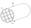
- FIG. 3 shows a honeycomb structure 20 as another example of the SCR catalyst 131.
- the honeycomb structure 20 has a structure in which a plurality of honeycomb units 21 (see FIG. 4) in which a plurality of through holes 11 a are arranged in parallel in the longitudinal direction with a partition wall 11 b therebetween are bonded via an adhesive layer 22.
- the configuration is the same as that of the honeycomb structure 10.
- the honeycomb unit 21 preferably has a cross-sectional area of 10 to 200 cm 2 in a cross section perpendicular to the longitudinal direction.
- the cross-sectional area of the cross section perpendicular to the longitudinal direction of the honeycomb unit 21 is less than 10 cm 2 , the pressure loss of the honeycomb structure 20 increases.
- the cross-sectional area of the cross section perpendicular to the longitudinal direction of the honeycomb unit 21 exceeds 200 cm 2 , the strength against the thermal stress generated in the honeycomb unit 11 becomes insufficient.
- the honeycomb unit 21 has the same configuration as the honeycomb unit 11 except for the cross-sectional area of the cross section perpendicular to the longitudinal direction.
- the adhesive layer 22 preferably has a thickness of 0.5 to 2.0 mm.
- the thickness of the adhesive layer 22 is less than 0.5 mm, the adhesive strength of the honeycomb unit 21 becomes insufficient.
- the thickness of the adhesive layer 21 exceeds 2.0 mm, the pressure loss of the honeycomb structure 20 increases.
- honeycomb structure 20 First, in the same manner as the honeycomb structure 10, a quadrangular columnar honeycomb unit 21 is manufactured. Next, an adhesive layer paste is applied to the outer peripheral surface excluding both end faces of the honeycomb unit 21, the honeycomb units 21 are sequentially bonded, and dried and solidified, whereby the aggregate of the honeycomb units 21 is manufactured.
- the adhesive layer paste is not particularly limited, and examples thereof include a mixture of inorganic binder and inorganic particles, a mixture of inorganic binder and inorganic fibers, a mixture of inorganic binder, inorganic particles, and inorganic fibers.
- the inorganic binder contained in the adhesive layer paste is not particularly limited, but is added as silica sol, alumina sol or the like, and two or more kinds may be used in combination. Among these, it is preferable to add as silica sol.
- the material constituting the inorganic particles contained in the adhesive layer paste is not particularly limited, and examples thereof include carbides such as silicon carbide, nitrides such as silicon nitride and boron nitride, and two or more kinds may be used in combination. Of these, silicon carbide is preferred because of its excellent thermal conductivity.
- the material constituting the inorganic fibers contained in the adhesive layer paste is not particularly limited, and examples thereof include silica alumina, mullite, alumina, silica and the like, and two or more kinds may be used in combination. Of these, alumina is preferable.
- the adhesive layer paste may contain an organic binder.
- the organic binder contained in the adhesive layer paste is not particularly limited, and examples thereof include polyvinyl alcohol, methyl cellulose, ethyl cellulose, carboxymethyl cellulose and the like, and two or more kinds may be used in combination.
- the adhesive layer paste may further contain balloons that are fine hollow spheres of oxide ceramics, a pore-forming agent, and the like.
- the balloon contained in the adhesive layer paste is not particularly limited, and examples thereof include an alumina balloon, a glass microballoon, a shirasu balloon, a fly ash balloon, and a mullite balloon, and two or more kinds may be used in combination. Among these, an alumina balloon is preferable.
- the pore former contained in the adhesive layer paste is not particularly limited, and examples thereof include spherical acrylic particles and graphite, and two or more kinds may be used in combination.
- the aggregate of the honeycomb units 21 is cut into a cylindrical shape, and then polished as necessary to produce an aggregate of the cylindrical honeycomb units 21.
- the honeycomb unit 21 whose cross section perpendicular to the longitudinal direction is formed into a predetermined shape is bonded to the aggregate of the cylindrical honeycomb units 21. May be produced.
- the shape of the cross section perpendicular to the longitudinal direction of the honeycomb unit 21 is preferably a sector having a central angle of 90 °.
- the outer peripheral coat layer paste is applied to the outer peripheral surface excluding both end surfaces of the aggregate of the cylindrical honeycomb units 21.
- the outer periphery coat layer paste may be the same as or different from the adhesive layer paste.
- a columnar honeycomb structure 20 is manufactured by drying and solidifying the aggregate of columnar honeycomb units 11 to which the outer periphery coating layer paste has been applied.
- an organic binder is contained in the adhesive layer paste and / or the outer peripheral coat layer paste, it is preferable to degrease.
- the degreasing conditions can be appropriately selected depending on the kind and amount of the organic matter, but it is preferably 20 minutes at 700 ° C.
- honeycomb structures 10 and 20 may not have the outer peripheral coat layer 12 formed thereon.
- honeycomb unit 11 or 21 a honeycomb structure having a honeycomb unit in which a plurality of through holes are arranged in parallel in the longitudinal direction with a partition wall therebetween and on which zeolite is supported may be used.
- the material constituting the honeycomb unit on which zeolite is supported is not particularly limited, and examples thereof include cordierite.
- the zeolite supported on the honeycomb unit is not particularly limited, and examples thereof include ⁇ -type zeolite, ZSM-5-type zeolite, and phosphate-based zeolite, and two or more kinds may be used in combination. Among them, phosphate zeolite is preferable because of its excellent NOx purification performance.
- phosphate zeolite examples include SAPO such as SAPO-5, SAPO-11, and SAPO-34; MeAPO; MeAPSO and the like.
- the zeolite is preferably ion-exchanged with copper ions and / or iron ions, and more preferably ion-exchanged with copper ions in consideration of NOx purification performance.
- the zeolite ion-exchanged with copper ions and / or iron ions preferably has an ion exchange amount of 1.0 to 5.0% by mass.
- metal ions for ion-exchange of zeolite are not limited to copper ions and / or iron ions, and include transition metal ions that can improve NOx purification performance.
- FIG. 5 shows a modification of the exhaust gas purification system 100.
- the exhaust gas purification system 200 has the same configuration as the exhaust gas purification system 100 except that an exhaust gas purification device 210 is installed instead of the exhaust gas purification devices 120 and 130.
- the exhaust gas purifying device 210 can be manufactured by canning the metal container 213 in a state where the holding sealing material 212 is disposed on the outer peripheral portions of the DPF 121 and the SCR catalyst 131. For this reason, the exhaust gas purification system 200 can purify the exhaust gas of the diesel engine.
- the exhaust gas purification system 200 includes means for supplying ammonia (such as an injection nozzle for injecting ammonia or a compound that decomposes to generate ammonia into the pipe 140 between the exhaust gas purification device 110 and the exhaust gas purification device 210). (Shown) is provided. As a result, ammonia is supplied into the pipe 140, so that the SCR catalyst 131 reduces NOx contained in the exhaust gas.
- ammonia such as an injection nozzle for injecting ammonia or a compound that decomposes to generate ammonia into the pipe 140 between the exhaust gas purification device 110 and the exhaust gas purification device 210.
- the exhaust gas purification system 200 can reduce the arrangement space of the exhaust gas purification device 210 as compared with the exhaust gas purification system 100.
- the exhaust gas purification method of the present invention is a method of purifying exhaust gas using the exhaust gas purification device of the present invention, detailed description thereof is omitted.
- a part means a mass part.
- DOC-1 A commercially available cordierite honeycomb structure carrying an oxidation catalyst was used.
- the honeycomb structure has a cylindrical shape with a diameter of 228.6 mm and a length of 114.3 mm.
- [DPF-1] 60 parts of ⁇ -type silicon carbide having an average particle diameter of 11 ⁇ m and 40 parts of ⁇ -type silicon carbide having an average particle diameter of 0.5 ⁇ m were mixed. Next, 5 parts of carboxymethyl cellulose and 10 parts of water were added and mixed and kneaded. Furthermore, a small amount of glycerin and a lubricant unilube (manufactured by NOF Corporation) were added and mixed and kneaded to prepare a raw material paste.
- the raw material paste was extruded using an extruder, and a cylindrical honeycomb formed body was produced. Then, the honeycomb formed body was dried using a microwave dryer and a hot air dryer, and a honeycomb dried body was manufactured.
- the raw material paste was filled into one end portion of the through hole of the dried honeycomb body.
- the honeycomb formed body was dried using a microwave dryer and a hot air dryer, and then degreased.
- the honeycomb unit was manufactured by firing at 2200 ° C. for 3 hours in an argon atmosphere.
- the honeycomb unit has a square prism shape with a side of 34.3 mm and a length of 203.2 mm, a density of through holes of 46.5 pieces / cm 2 , a partition wall thickness of 0.15 mm, and an average pore diameter of 11 ⁇ m.
- the porosity was 42%.
- the adhesive layer paste was applied to the outer peripheral surface excluding both ends of the honeycomb unit so that the adhesive layer had a thickness of 1.0 mm, and 36 honeycomb units were adhered and dried and solidified at 120 ° C.
- a diamond cutter was used to cut into a cylindrical shape so that the cross section perpendicular to the longitudinal direction was substantially point-symmetric, and a honeycomb unit aggregate was produced.
- silica alumina fiber having an average fiber diameter of 50 ⁇ m 30.2 parts of silicon carbide having an average particle diameter of 0.3 ⁇ m, 7 parts of silica sol having a solid content of 30% by mass, 0.5 part of carboxymethylcellulose, and 39 parts of water was mixed and kneaded to prepare a peripheral coat layer paste.
- An outer peripheral coating layer paste is applied to the outer peripheral surface excluding both ends of the aggregate of honeycomb units, and then dried and solidified at 120 ° C. to form a cylindrical honeycomb structure having a diameter of 228.6 mm and a length of 203.2 mm The body was made.
- the honeycomb structure has a cylindrical shape with a diameter of 228.6 mm and a length of 279.4 mm, and an outer peripheral coat layer with a thickness of 0.2 mm is formed on the outer peripheral surface excluding both ends of a single honeycomb unit. ing.
- the honeycomb unit has a density of through holes of 46.5 / cm 2 , a partition wall thickness of 0.30 mm, an average pore diameter of 15 ⁇ m, a porosity of 48%, and no catalyst is supported.
- the raw material paste was extruded using an extruder, and a cylindrical honeycomb formed body was produced. Then, the honeycomb formed body was dried at 110 ° C. for 10 minutes using a microwave dryer and a hot air dryer, and then degreased at 400 ° C. for 5 hours. Next, the honeycomb fired body was manufactured by firing at 700 ° C. for 2 hours.
- the honeycomb structure 10 was manufactured by immersing the honeycomb structure in an aqueous copper nitrate solution to ion-exchange zeolite with copper ions.
- the ion exchange amount of the zeolite was measured by ICP emission analysis using ICPS-8100 (manufactured by Shimadzu Corporation), and it was 2.7% by mass.
- the honeycomb structure 10 has a cylindrical shape with a diameter of 228.6 mm and a length of 203.2 mm.
- the honeycomb unit 11 has a partition wall thickness of 0.28 mm and a through hole density of 62 holes / cm 2. It was.
- [SCR catalyst-2] A commercially available honeycomb structure made of cordierite was immersed in a dispersion of zeolite ion-exchanged by 2.7% by mass with copper ions to carry 170 g / L of zeolite.
- the honeycomb structure has a cylindrical shape with a diameter of 228.6 mm and a length of 304.8 mm, and an outer peripheral coat layer with a thickness of 0.2 mm is formed on the outer peripheral surface excluding both ends of a single honeycomb unit. ing.
- the honeycomb unit had a partition wall thickness of 0.28 mm and a through hole density of 62 holes / cm 2 .
- DOC-1, DPF-1, and SCR catalyst-1 are used as DOC111, DPF121, and SCR catalyst 131, respectively, so that the distance between DOC111 and DPF121 is 800 mm, and the distance between DPF121 and SCR catalyst 131 is 30 mm. It installed and produced the exhaust gas purification system 200 (refer FIG. 5). At this time, the injection nozzle was installed so that urea water was injected into the pipe 140 at a position where the distance from the DPF 121 was 600 mm.
- Example 2 Exhaust gas purification system 100 was produced in the same manner as in Example 1 except that DPF-2 was used as DPF 121.
- Example 3 Exhaust gas purification system 100 was produced in the same manner as in Example 1 except that SCR catalyst-2 was used as SCR catalyst 131.
- Example 4 Exhaust gas purification system 100 was produced in the same manner as in Example 1 except that DPF-2 and SCR catalyst-2 were used as DPF 121 and SCR catalyst 131, respectively.
- DOC-1, DPF-1, and SCR catalyst-1 are used as DOC111, DPF121, and SCR catalyst 131, respectively, so that the distance between DOC111 and DPF121 is 800 mm, and the distance between DPF121 and SCR catalyst 131 is 200 mm. It installed and produced the exhaust gas purification system 100 (refer FIG. 1). At this time, the injection nozzle was installed so that urea water was injected into the pipe 140 at a position where the distance from the DPF 121 was 600 mm.
- the NOx purification rate is measured by installing NOx sensors upstream and downstream of the SCR catalyst 131 with respect to the direction of exhaust gas flow, and detecting the concentration of NOx in the exhaust gas for 30 minutes.
- (NOx inflow-NOx outflow) / (NOx inflow) x 100 [%] Is the average value of the values represented by At this time, steady operation was performed under the condition that the temperature of the exhaust gas was 250 ° C. Further, when the temperature of the SCR catalyst 131 is 180 ° C. or higher, the molar ratio of ammonia to NOx detected by the NOx sensor installed on the upstream side of the SCR catalyst 131 becomes 1 with respect to the flow direction of the exhaust gas.
- urea water was injected into the pipe 140 or 150 using an injection nozzle. Furthermore, urea water was diffused in the radial direction of the pipe 140 or 150 using a mixer and a swirler.
- Table 1 shows the measurement results of the length of the exhaust gas purification system and the NOx purification rate together with the types of DOC, DPF and SCR catalyst.
- the length of the exhaust gas purification system means the distance from the upstream end of the DOC 111 to the downstream end of the SCR catalyst 131 with respect to the flow direction of the exhaust gas.
- the exhaust gas purification system 200 of Examples 1 to 4 and the exhaust gas purification system 100 of Example 5 have the length of the exhaust gas purification system set to 1351-1529 mm while maintaining the NOx purification rate at 72 to 85%. I understand that I can do it.
- the exhaust gas purification system 200 of Example 1 has a NOx purification rate of 5% higher than the exhaust gas purification system 100 of Example 5 in which the DOC 111, the DPF 121, and the SCR catalyst 131 are the same, and the length of the exhaust gas purification system. Is 170 mm shorter.
- the exhaust gas purification system of Comparative Example 1 is the same in length as the exhaust gas purification system 100 of Example 5 in which the DOC 111, the DPF 121, and the SCR catalyst 131 are the same, but the NOx purification rate is 47%. It turns out that it falls to.
- the exhaust gas purification system of Comparative Example 2 has substantially the same NOx purification rate as the exhaust gas purification system 100 of Example 5 in which the DOC 111, the DPF 121, and the SCR catalyst 131 are the same, but the length of the exhaust gas purification system is 2021 mm. It can be seen that it increases.
Abstract
An exhaust gas purification system according to the present invention is provided with an oxidation catalyst, a filter and a selective catalyst reduction catalyst which are arranged in this order in an exhaust gas passage of a diesel engine in the direction of the flow of an exhaust gas, wherein a means for supplying ammonia is provided between the oxidation catalyst and the filter.
Description
本発明は、排ガス浄化システム及び排ガス浄化方法に関する。
The present invention relates to an exhaust gas purification system and an exhaust gas purification method.
従来、自動車の排ガスを浄化するシステムの一つとして、アンモニアを用いて、NOxを窒素と水に還元するSCR(選択触媒還元)システムが知られている。
Conventionally, an SCR (Selective Catalytic Reduction) system that uses ammonia to reduce NOx to nitrogen and water has been known as one of systems for purifying automobile exhaust gas.
また、SCRシステムにおいて、アンモニアを吸着する材料として、ゼオライトが知られている。
Also, zeolite is known as a material that adsorbs ammonia in the SCR system.
特許文献1には、ディーゼルエンジンの排気通路に、NOxを還元浄化するSCR触媒を配設すると共に、SCR触媒の上流側に、上流側から順にDOC(酸化触媒)と、DPF(フィルタ)を直列に配設し、DPFとSCR触媒との間の排気通路に還元剤を供給及び噴射する装置を配置した排ガス浄化装置が開示されている。
In Patent Document 1, an SCR catalyst for reducing and purifying NOx is disposed in an exhaust passage of a diesel engine, and a DOC (oxidation catalyst) and a DPF (filter) are connected in series from the upstream side to the upstream side of the SCR catalyst. And an exhaust gas purification device in which a device for supplying and injecting a reducing agent is disposed in an exhaust passage between the DPF and the SCR catalyst.
しかしながら、排ガス中に含まれるNOxを十分に浄化するためには、DPFとSCR触媒との間の距離を確保してアンモニアをSCR触媒の径方向、即ち、外周部に拡散させる必要があり、排ガス浄化装置の配置スペースを小さくすることができないという問題がある。
However, in order to sufficiently purify NOx contained in the exhaust gas, it is necessary to ensure the distance between the DPF and the SCR catalyst and diffuse ammonia in the radial direction of the SCR catalyst, that is, in the outer peripheral portion. There exists a problem that the arrangement | positioning space of a purification apparatus cannot be made small.
本発明は、上記の従来技術が有する問題に鑑み、NOxの浄化性能を維持しながら、排ガス浄化装置の配置スペースを小さくすることが可能な排ガス浄化システム及び該排ガス浄化システムを用いる排ガス浄化方法を提供することを目的とする。
In view of the above-described problems of the conventional technology, the present invention provides an exhaust gas purification system capable of reducing the arrangement space of the exhaust gas purification device while maintaining the NOx purification performance, and an exhaust gas purification method using the exhaust gas purification system. The purpose is to provide.
本発明の排ガス浄化システムは、ディーゼルエンジンの排気経路の排ガスの流れる方向に対して、酸化触媒、フィルタ及び選択触媒還元触媒が順次設けられていると共に、前記酸化触媒及び前記フィルタの間にアンモニアを供給する手段が設けられている。
In the exhaust gas purification system of the present invention, an oxidation catalyst, a filter, and a selective catalyst reduction catalyst are sequentially provided in the exhaust gas flow direction of the exhaust path of the diesel engine, and ammonia is introduced between the oxidation catalyst and the filter. Means for supplying is provided.
前記フィルタは、複数の貫通孔が隔壁を隔てて長手方向に並設されていると共に、該貫通孔の一端が目封じされているハニカムユニットを有するハニカム構造体であることが望ましい。
The filter is preferably a honeycomb structure having a honeycomb unit in which a plurality of through holes are arranged in parallel in the longitudinal direction with a partition wall therebetween and one end of the through hole is sealed.
前記フィルタは、触媒が担持されていないことが望ましい。
It is desirable that the filter does not carry a catalyst.
前記ハニカムユニットは、炭化ケイ素を含むことが望ましい。
The honeycomb unit preferably includes silicon carbide. *
前記ハニカムユニットは、隔壁の厚さが0.10mm以上0.18mm以下であることが望ましい。
The honeycomb unit preferably has a partition wall thickness of 0.10 mm to 0.18 mm. *
前記選択触媒還元触媒は、複数の貫通孔が隔壁を隔てて長手方向に並設されているハニカムユニットを有するハニカム構造体であり、該ハニカムユニットは、ゼオライト及び無機バインダを含むことが望ましい。
The selective catalyst reduction catalyst is a honeycomb structure having a honeycomb unit in which a plurality of through holes are arranged in parallel in the longitudinal direction with a partition wall therebetween, and the honeycomb unit preferably contains a zeolite and an inorganic binder. *
前記選択触媒還元触媒に含まれるハニカムユニットは、無機繊維、鱗片状物質、テトラポット状物質及び三次元針状物質からなる群より選択される一種以上をさらに含むことが望ましい。
The honeycomb unit included in the selective catalyst reduction catalyst preferably further includes one or more selected from the group consisting of inorganic fibers, scale-like substances, tetrapot-like substances, and three-dimensional needle-like substances. *
前記ゼオライトは、リン酸塩系ゼオライトであることが望ましい。
The zeolite is preferably a phosphate-based zeolite. *
前記フィルタ及び前記選択触媒還元触媒は、一つの金属容器内に設けられていることが望ましい。
The filter and the selective catalytic reduction catalyst are preferably provided in a single metal container. *
本発明の排ガス浄化方法は、本発明の排ガス浄化システムを用いて排ガスを浄化する。
The exhaust gas purification method of the present invention purifies exhaust gas using the exhaust gas purification system of the present invention.
本発明によれば、NOxの浄化性能を維持しながら、排ガス浄化装置の配置スペースを小さくすることが可能な排ガス浄化システム及び該排ガス浄化システムを用いる排ガス浄化方法を提供することができる。
According to the present invention, it is possible to provide an exhaust gas purification system capable of reducing the arrangement space of the exhaust gas purification device while maintaining NOx purification performance, and an exhaust gas purification method using the exhaust gas purification system.
次に、本発明を実施するための形態を図面と共に説明する。
Next, an embodiment for carrying out the present invention will be described with reference to the drawings.
図1に、本発明の排ガス浄化システムの一例を示す。排ガス浄化システム100は、排ガス浄化装置110、120及び130が配管140及び150を介して接続されている。このとき、排ガス浄化装置110は、DOC(酸化触媒)111の外周部に保持シール材112を配置した状態で、金属容器(シェル)113にキャニングすることにより作製することができる。また、排ガス浄化装置120は、DPF(フィルタ)121の外周部に保持シール材122を配置した状態で、金属容器123にキャニングすることにより作製することができる。さらに、排ガス浄化装置130は、SCR(選択触媒還元)触媒131の外周部に保持シール材132を配置した状態で、金属容器133にキャニングすることにより作製することができる。このため、排ガス浄化システム100は、ディーゼルエンジンの排ガスを浄化することができる。
FIG. 1 shows an example of the exhaust gas purification system of the present invention. In the exhaust gas purification system 100, exhaust gas purification devices 110, 120 and 130 are connected via pipes 140 and 150. At this time, the exhaust gas purification device 110 can be manufactured by canning the metal container (shell) 113 in a state where the holding sealing material 112 is disposed on the outer periphery of the DOC (oxidation catalyst) 111. Further, the exhaust gas purifying device 120 can be manufactured by performing canning on the metal container 123 in a state where the holding sealing material 122 is disposed on the outer peripheral portion of the DPF (filter) 121. Further, the exhaust gas purifying device 130 can be manufactured by performing canning on the metal container 133 in a state where the holding sealing material 132 is disposed on the outer peripheral portion of the SCR (selective catalyst reduction) catalyst 131. For this reason, the exhaust gas purification system 100 can purify the exhaust gas of the diesel engine.
さらに、排ガス浄化システム100には、排ガス浄化装置110と排ガス浄化装置120の間の配管140内に、アンモニア又は分解してアンモニアを発生させる化合物を噴射する噴射ノズル等のアンモニアを供給する手段(不図示)が設けられている。これにより、配管140内にアンモニアが供給されるため、SCR触媒131により、排ガス中に含まれるNOxが還元される。
Further, in the exhaust gas purification system 100, means for supplying ammonia (such as an injection nozzle for injecting ammonia or a compound that decomposes to generate ammonia into the pipe 140 between the exhaust gas purification device 110 and the exhaust gas purification device 120). (Shown) is provided. As a result, ammonia is supplied into the pipe 140, so that the SCR catalyst 131 reduces NOx contained in the exhaust gas.
分解してアンモニアを発生させる化合物としては、配管140内で排ガスにより加熱されて、アンモニアを発生させることが可能であれば、特に限定されないが、貯蔵安定性に優れるため、尿素水が好ましい。
The compound that decomposes to generate ammonia is not particularly limited as long as it can be heated by exhaust gas in the pipe 140 and generate ammonia, but urea water is preferable because of excellent storage stability.
なお、尿素水は、配管140内で排ガスにより加熱されて、加水分解し、アンモニアが発生する。
The urea water is heated by the exhaust gas in the pipe 140 and hydrolyzed to generate ammonia.
排ガス浄化システム100では、配管140内にアンモニアが供給されるため、DPF121とSCR触媒131との間の距離を確保しなくても、アンモニアをSCR触媒131の径方向、即ち、外周部に拡散させることができる。その結果、NOxの浄化性能を維持しながら、排ガス浄化装置120及び130の配置スペースを小さくすることができる。このとき、配管150を省略して、排ガス浄化装置120と排ガス浄化装置130を直接接続してもよい。
In the exhaust gas purification system 100, since ammonia is supplied into the pipe 140, the ammonia is diffused in the radial direction of the SCR catalyst 131, that is, in the outer peripheral portion without securing the distance between the DPF 121 and the SCR catalyst 131. be able to. As a result, it is possible to reduce the arrangement space of the exhaust gas purification devices 120 and 130 while maintaining the NOx purification performance. At this time, the piping 150 may be omitted and the exhaust gas purification device 120 and the exhaust gas purification device 130 may be directly connected.
これに対して、従来の排ガス浄化システムでは、配管150内にアンモニアが供給されるため、排ガス中に含まれるNOxを十分に浄化するためには、DPF121とSCR触媒131との間の距離を確保してアンモニアをSCR触媒131の径方向、即ち、外周部に拡散させる必要がある。その結果、排ガス浄化装置120及び130の配置スペースを小さくすることができない。
On the other hand, in the conventional exhaust gas purification system, ammonia is supplied into the pipe 150. Therefore, in order to sufficiently purify NOx contained in the exhaust gas, a distance between the DPF 121 and the SCR catalyst 131 is secured. Thus, it is necessary to diffuse ammonia in the radial direction of the SCR catalyst 131, that is, in the outer peripheral portion. As a result, the arrangement space of the exhaust gas purification devices 120 and 130 cannot be reduced.
DOC111は、複数の貫通孔が隔壁を隔てて長手方向に並設されていると共に、触媒が担持されているハニカムユニットを有するハニカム構造体である。
The DOC 111 is a honeycomb structure having a honeycomb unit in which a plurality of through holes are arranged in parallel in the longitudinal direction with a partition wall therebetween and a catalyst is supported.
DOC111に含まれるハニカムユニットを構成する材料としては、特に限定されないが、コージェライト等が挙げられる。
Although it does not specifically limit as a material which comprises the honeycomb unit contained in DOC111, Cordierite etc. are mentioned.
DOC111に含まれるハニカムユニットに担持されている触媒としては、特に限定されないが、白金、パラジウム、ロジウム等が挙げられ、二種以上併用してもよい。
Although it does not specifically limit as a catalyst currently carry | supported by the honeycomb unit contained in DOC111, Platinum, palladium, rhodium, etc. are mentioned, You may use 2 or more types together.
DOC111に含まれるハニカムユニットは、触媒を担持する触媒担持層が形成されていてもよい。
In the honeycomb unit included in the DOC 111, a catalyst supporting layer for supporting a catalyst may be formed.
DOC111に含まれるハニカムユニットに形成されている触媒担持層を構成する材料としては、特に限定されないが、アルミナ等が挙げられる。
Although it does not specifically limit as a material which comprises the catalyst support layer currently formed in the honeycomb unit contained in DOC111, Alumina etc. are mentioned.
保持シール材112、122及び132としては、特に限定されないが、無機繊維を含むマットが好ましい。
The holding sealing materials 112, 122 and 132 are not particularly limited, but a mat containing inorganic fibers is preferable.
DPF121は、複数の貫通孔が隔壁を隔てて長手方向に並設されていると共に、貫通孔の一端が目封じされているハニカムユニットを有するハニカム構造体である。
The DPF 121 is a honeycomb structure having a honeycomb unit in which a plurality of through holes are arranged in parallel in the longitudinal direction with a partition wall therebetween and one end of the through hole is sealed.
DPF121に含まれるハニカムユニットを構成する材料としては、特に限定されないが、炭化ケイ素(SiC)、ケイ素結合炭化ケイ素(SiSiC)、コージェライト、チタン酸アルミニウム等が挙げられるが、DPF121に溜まった煤を大量に燃焼させてもクラックが発生しにくいことから、炭化ケイ素(SiC)又はケイ素結合炭化ケイ素(SiSiC)が好ましい。
The material constituting the honeycomb unit included in the DPF 121 is not particularly limited, and examples thereof include silicon carbide (SiC), silicon-bonded silicon carbide (SiSiC), cordierite, aluminum titanate, and the like. Silicon carbide (SiC) or silicon-bonded silicon carbide (SiSiC) is preferred because cracks are unlikely to occur even when burned in large quantities.
DPF121に含まれるハニカムユニットは、白金、パラジウム、ロジウム等の触媒が担持されていない。これにより、配管140内に供給されたアンモニアの酸化を抑制することができる。また、触媒が担持されていないハニカムユニットを有するDPF121は、触媒反応に伴って温度が上昇しないため、ハニカムユニットの隔壁の厚さを小さくしても、ハニカムユニットの強度を維持することができる。
The honeycomb unit included in the DPF 121 does not carry a catalyst such as platinum, palladium, or rhodium. Thereby, oxidation of ammonia supplied into the pipe 140 can be suppressed. In addition, since the DPF 121 having a honeycomb unit on which no catalyst is supported does not rise in temperature due to the catalytic reaction, the strength of the honeycomb unit can be maintained even if the partition wall thickness of the honeycomb unit is reduced. *
DPF121に含まれるハニカムユニットは、隔壁の厚さが0.10~0.18mmであることが好ましい。DPF121に含まれるハニカムユニットの隔壁の厚さが0.10mm未満であると、DPF121の強度が低下する。一方、DPF121に含まれるハニカムユニットの隔壁の厚さが0.18mmを超えると、DPF121の圧力損失が増大するため、排ガス浄化装置120の配置スペースを小さくすることができない。
The honeycomb unit included in the DPF 121 preferably has a partition wall thickness of 0.10 to 0.18 mm. When the thickness of the partition wall of the honeycomb unit included in the DPF 121 is less than 0.10 mm, the strength of the DPF 121 is reduced. On the other hand, when the thickness of the partition wall of the honeycomb unit included in the DPF 121 exceeds 0.18 mm, the pressure loss of the DPF 121 increases, so that the arrangement space of the exhaust gas purification device 120 cannot be reduced.
SCR触媒131は、複数の貫通孔が隔壁を隔てて長手方向に並設されているハニカムユニットを有するハニカム構造体である。
The SCR catalyst 131 is a honeycomb structure having a honeycomb unit in which a plurality of through holes are arranged in parallel in the longitudinal direction with a partition wall therebetween.
図2に、SCR触媒131の一例として、ハニカム構造体10を示す。ハニカム構造体10は、ゼオライト及び無機バインダを含み、複数の貫通孔11aが隔壁11bを隔てて長手方向に並設されている単一のハニカムユニット11を有する。また、ハニカムユニット11の両端面を除く外周面に外周コート層12が形成されている。
FIG. 2 shows a honeycomb structure 10 as an example of the SCR catalyst 131. The honeycomb structure 10 includes a single honeycomb unit 11 that includes zeolite and an inorganic binder and has a plurality of through holes 11a arranged in parallel in the longitudinal direction with the partition walls 11b interposed therebetween. Further, the outer peripheral coat layer 12 is formed on the outer peripheral surface excluding both end surfaces of the honeycomb unit 11.
ハニカムユニット11に含まれるゼオライトとしては、特に限定されないが、β型ゼオライト、ZSM-5型ゼオライト、リン酸塩系ゼオライト等が挙げられ、二種以上併用してもよい。中でも、NOxの浄化性能に優れるため、リン酸塩系ゼオライトが好ましい。
The zeolite contained in the honeycomb unit 11 is not particularly limited, and examples thereof include β-type zeolite, ZSM-5-type zeolite, phosphate zeolite, and the like, and two or more kinds may be used in combination. Among them, phosphate zeolite is preferable because of its excellent NOx purification performance.
リン酸塩系ゼオライトとしては、SAPO-5、SAPO-11、SAPO-34等のSAPO(シリコアルミノホスフェート);MeAPO(メタロアルミノホスフェート);MeAPSO(金属骨格置換シリコアルミノホスフェート)等が挙げられる。
Examples of the phosphate zeolite include SAPO (silicoaluminophosphate) such as SAPO-5, SAPO-11, and SAPO-34; MeAPO (metalloaluminophosphate); MeAPSO (metal skeleton-substituted silicoaluminophosphate) and the like.
ゼオライトは、NOxの浄化性能が向上するため、銅イオン及び/又は鉄イオンによりイオン交換されていることが好ましく、銅イオンによりイオン交換されていることがより好ましい。
Zeolite is preferably ion-exchanged with copper ions and / or iron ions, more preferably ion-exchanged with copper ions in order to improve NOx purification performance.
銅イオン及び/又は鉄イオンによりイオン交換されているゼオライトは、イオン交換量が1.0~5.0質量%であることが好ましい。
The zeolite ion-exchanged with copper ions and / or iron ions preferably has an ion exchange amount of 1.0 to 5.0% by mass.
なお、ゼオライトをイオン交換する金属イオンとしては、銅イオン及び/又は鉄イオンに限定されず、NOxの浄化性能を向上させることが可能な遷移金属イオン等が挙げられる。
Note that the metal ions for ion-exchange of zeolite are not limited to copper ions and / or iron ions, and include transition metal ions that can improve NOx purification performance.
ゼオライトの一次粒子又は二次粒子の平均粒径は、0.5~10μmであることが好ましく、1~5μmがより好ましい。ゼオライトの一次粒子又は二次粒子の平均粒径が0.5μm未満であると、ハニカムユニット11の隔壁11bの内部まで排ガスが侵入しにくくなって、ゼオライトがNOxの浄化に有効に利用されなくなる。一方、ゼオライトの一次粒子又は二次粒子の平均粒径が10μmを超えると、ハニカムユニット11中の気孔の数が少なくなるため、ハニカムユニット11の隔壁11bの内部まで排ガスが侵入しにくくなり、ゼオライトがNOxの浄化に有効に利用されなくなる。
The average particle diameter of the primary particles or secondary particles of the zeolite is preferably 0.5 to 10 μm, and more preferably 1 to 5 μm. When the average particle diameter of the primary particles or secondary particles of the zeolite is less than 0.5 μm, the exhaust gas hardly enters the partition walls 11b of the honeycomb unit 11, and the zeolite is not effectively used for NOx purification. On the other hand, when the average particle size of the primary particles or secondary particles of the zeolite exceeds 10 μm, the number of pores in the honeycomb unit 11 is reduced, so that the exhaust gas does not easily enter the partition walls 11b of the honeycomb unit 11. Is not effectively used for NOx purification.
ハニカムユニット11は、見掛けの体積当たりのゼオライトの含有量が230~400g/Lであることが好ましい。ハニカムユニット11の見掛けの体積当たりのゼオライトの含有量が230g/L未満であると、NOxの浄化性能を向上させるためにハニカムユニット11の見掛けの体積を大きくする必要がある。一方、ハニカムユニット11の見掛けの体積当たりのゼオライトの含有量が400g/Lを超えると、ハニカムユニット11の強度が不十分になったり、ハニカムユニット11の開口率が小さくなったりする。
The honeycomb unit 11 preferably has a zeolite content of 230 to 400 g / L per apparent volume. If the zeolite content per apparent volume of the honeycomb unit 11 is less than 230 g / L, it is necessary to increase the apparent volume of the honeycomb unit 11 in order to improve the NOx purification performance. On the other hand, if the content of zeolite per apparent volume of the honeycomb unit 11 exceeds 400 g / L, the strength of the honeycomb unit 11 becomes insufficient or the aperture ratio of the honeycomb unit 11 becomes small.
ハニカムユニット11に含まれる無機バインダとしては、特に限定されないが、アルミナゾル、シリカゾル、チタニアゾル、水ガラス、セピオライト、アタパルジャイト、ベーマイト等に含まれる固形分が挙げられ、二種以上併用してもよい。
The inorganic binder contained in the honeycomb unit 11 is not particularly limited, and examples thereof include solids contained in alumina sol, silica sol, titania sol, water glass, sepiolite, attapulgite, boehmite and the like, and two or more kinds may be used in combination.
ハニカムユニット11中の無機バインダの含有量は、5~30質量%であることが好ましく、10~20質量%がより好ましい。ハニカムユニット11中の無機バインダの含有量が5質量%未満であると、ハニカムユニット11の強度が低下する。一方、ハニカムユニット11中の無機バインダの含有量が30質量%を超えると、ハニカムユニット11の押出成形が困難になる。
The content of the inorganic binder in the honeycomb unit 11 is preferably 5 to 30% by mass, and more preferably 10 to 20% by mass. When the content of the inorganic binder in the honeycomb unit 11 is less than 5% by mass, the strength of the honeycomb unit 11 is lowered. On the other hand, when the content of the inorganic binder in the honeycomb unit 11 exceeds 30% by mass, the extrusion molding of the honeycomb unit 11 becomes difficult.
ハニカムユニット11は、強度を向上させるために、無機繊維、鱗片状物質、テトラポット状物質及び三次元針状物質からなる群より選択される一種以上をさらに含むことが好ましい。
The honeycomb unit 11 preferably further includes at least one selected from the group consisting of inorganic fibers, scale-like substances, tetrapot-like substances, and three-dimensional needle-like substances in order to improve the strength.
ハニカムユニット11に含まれる無機繊維を構成する材料としては、特に限定されないが、アルミナ、シリカ、炭化ケイ素、シリカアルミナ、ガラス、チタン酸カリウム、ホウ酸アルミニウム等が挙げられ、二種以上併用してもよい。
The material constituting the inorganic fiber contained in the honeycomb unit 11 is not particularly limited, and examples thereof include alumina, silica, silicon carbide, silica alumina, glass, potassium titanate, and aluminum borate. Also good.
ハニカムユニット11に含まれる無機繊維のアスペクト比は、2~1000であることが好ましく、5~800がより好ましく、10~500がさらに好ましい。ハニカムユニット11に含まれる無機繊維のアスペクト比が2未満であると、ハニカムユニット11の強度を向上させる効果が小さくなる。一方、ハニカムユニット11に含まれる無機繊維のアスペクト比が1000を超えると、ハニカムユニット11を押出成形する際に金型に目詰まり等が発生したり、無機繊維が折れて、ハニカムユニット11の強度を向上させる効果が小さくなったりする。
The aspect ratio of the inorganic fibers contained in the honeycomb unit 11 is preferably 2 to 1000, more preferably 5 to 800, and even more preferably 10 to 500. When the aspect ratio of the inorganic fibers contained in the honeycomb unit 11 is less than 2, the effect of improving the strength of the honeycomb unit 11 is reduced. On the other hand, when the aspect ratio of the inorganic fibers contained in the honeycomb unit 11 exceeds 1000, the mold is clogged when the honeycomb unit 11 is extruded, or the inorganic fibers break and the strength of the honeycomb unit 11 is increased. The effect of improving the quality is reduced.
鱗片状物質は、平たい物質を意味し、厚さが0.2~5.0μmであることが好ましく、最大長さが10~160μmであることが好ましく、厚さに対する最大長さの比が3~250であることが好ましい。
The scaly substance means a flat substance, preferably having a thickness of 0.2 to 5.0 μm, preferably having a maximum length of 10 to 160 μm, and a ratio of the maximum length to the thickness of 3 It is preferable that it is -250.
ハニカムユニット11に含まれる鱗片状物質を構成する材料としては、特に限定されないが、ガラス、白雲母、アルミナ、シリカ等が挙げられ、二種以上併用してもよい。
The material constituting the scaly substance contained in the honeycomb unit 11 is not particularly limited, and examples thereof include glass, muscovite, alumina, silica and the like, and two or more kinds may be used in combination.
テトラポット状物質は、針状部が三次元に延びている物質を意味し、針状部の平均針状長さが5~30μmであることが好ましく、針状部の平均径が0.5~5.0μmであることが好ましい。
The tetrapot-like substance means a substance in which the needle-like portion extends three-dimensionally. The average needle-like length of the needle-like portion is preferably 5 to 30 μm, and the average diameter of the needle-like portion is 0.5. It is preferable that the thickness is ˜5.0 μm.
ハニカムユニット11に含まれるテトラポット状物質を構成する材料としては、特に限定されないが、酸化亜鉛等が挙げられ、二種以上併用してもよい。
Although it does not specifically limit as a material which comprises the tetrapot-like substance contained in the honeycomb unit 11, Zinc oxide etc. are mentioned, You may use together 2 or more types.
三次元針状物質は、針状部同士がそれぞれの針状部の中央付近でガラス等の無機化合物により結合されている物質を意味し、針状部の平均針状長さが5~30μmであることが好ましく、針状部の平均径が0.5~5.0μmであることが好ましい。
The three-dimensional acicular substance means a substance in which the acicular parts are bonded by an inorganic compound such as glass near the center of each acicular part, and the average acicular length of the acicular parts is 5 to 30 μm. It is preferable that the average diameter of the needle-shaped part is 0.5 to 5.0 μm.
また、三次元針状物質は、複数の針状部が三次元に連なっていてもよく、針状部の直径が0.1~5.0μmであることが好ましく、長さが0.3~30.0μmであることが好ましく、直径に対する長さの比が1.4~50.0であることが好ましい。
The three-dimensional acicular substance may have a plurality of acicular portions that are three-dimensionally connected, and preferably has a needle-like diameter of 0.1 to 5.0 μm and a length of 0.3 to It is preferably 30.0 μm, and the ratio of length to diameter is preferably 1.4 to 50.0.
ハニカムユニット11に含まれる三次元針状物質を構成する材料としては、特に限定されないが、アルミナ、シリカ、炭化ケイ素、シリカアルミナ、ガラス、チタン酸カリウム、ホウ酸アルミニウム、ベーマイト等が挙げられ、二種以上併用してもよい。
The material constituting the three-dimensional acicular substance contained in the honeycomb unit 11 is not particularly limited, and examples thereof include alumina, silica, silicon carbide, silica alumina, glass, potassium titanate, aluminum borate, boehmite, and the like. Two or more species may be used in combination.
ハニカムユニット11中の無機繊維、鱗片状物質、テトラポット状物質及び三次元針状物質の含有量は、3~50質量%であることが好ましく、3~30質量%がより好ましく、5~20質量%がさらに好ましい。ハニカムユニット11中の無機繊維、鱗片状物質、テトラポット状物質及び三次元針状物質の含有量が3質量%未満であると、ハニカムユニット11の強度を向上させる効果が小さくなる。一方、ハニカムユニット11中の無機繊維、鱗片状物質、テトラポット状物質及び三次元針状物質の含有量が50質量%を超えると、ハニカムユニット11中のゼオライトの含有量が低下して、NOxの浄化性能が低下する。
The content of inorganic fiber, scale-like substance, tetrapot-like substance and three-dimensional needle-like substance in the honeycomb unit 11 is preferably 3 to 50% by mass, more preferably 3 to 30% by mass. More preferred is mass%. When the content of the inorganic fiber, scale-like substance, tetrapot-like substance and three-dimensional needle-like substance in the honeycomb unit 11 is less than 3% by mass, the effect of improving the strength of the honeycomb unit 11 becomes small. On the other hand, when the content of inorganic fibers, scale-like substances, tetrapot-like substances, and three-dimensional needle-like substances in the honeycomb unit 11 exceeds 50% by mass, the zeolite content in the honeycomb unit 11 decreases, and NOx The purification performance is reduced.
ハニカムユニット11は、気孔率が20~50%であることが好ましい。ハニカムユニット11の気孔率が20%未満であると、ハニカムユニット11の隔壁11bの内部まで排ガスが侵入しにくくなって、ゼオライトがNOxの浄化に有効に利用されなくなる。一方、ハニカムユニット11の気孔率が50%を超えると、ハニカムユニット11の強度が不十分となる。
The honeycomb unit 11 preferably has a porosity of 20 to 50%. When the porosity of the honeycomb unit 11 is less than 20%, the exhaust gas hardly enters the partition walls 11b of the honeycomb unit 11 and the zeolite is not effectively used for NOx purification. On the other hand, when the porosity of the honeycomb unit 11 exceeds 50%, the strength of the honeycomb unit 11 becomes insufficient.
なお、ハニカムユニット11の気孔率は、水銀圧入法を用いて測定することができる。
Note that the porosity of the honeycomb unit 11 can be measured using a mercury intrusion method.
ハニカムユニット11は、開口率が50~75%であることが好ましい。ハニカムユニット11の開口率が50%未満であると、ゼオライトがNOxの浄化に有効に利用されなくなる。一方、ハニカムユニット11の開口率が75%を超えると、ハニカムユニット11の強度が不十分となる。
The honeycomb unit 11 preferably has an opening ratio of 50 to 75%. If the aperture ratio of the honeycomb unit 11 is less than 50%, the zeolite is not effectively used for NOx purification. On the other hand, when the aperture ratio of the honeycomb unit 11 exceeds 75%, the strength of the honeycomb unit 11 becomes insufficient.
ハニカムユニット11は、貫通孔11aの密度が31~155個/cm2であることが好ましい。ハニカムユニット11の貫通孔11aの密度が31個/cm2未満であると、排ガスとゼオライトが接触しにくくなって、NOxの浄化性能が低下する。一方、ハニカムユニット11の貫通孔11aの密度が155個/cm2を超えると、ハニカム構造体10の圧力損失が増大する。
In the honeycomb unit 11, the density of the through holes 11a is preferably 31 to 155 / cm 2 . When the density of the through holes 11a of the honeycomb unit 11 is less than 31 / cm 2 , the exhaust gas and the zeolite are difficult to contact with each other, and the NOx purification performance is lowered. On the other hand, when the density of the through holes 11a of the honeycomb unit 11 exceeds 155 / cm 2 , the pressure loss of the honeycomb structure 10 increases.
ハニカムユニット11の隔壁11bの厚さは、0.1~0.4mmであることが好ましく、0.1~0.3mmがより好ましい。ハニカムユニット11の隔壁11bの厚さが0.1mm未満であると、ハニカムユニット11の強度が低下する。一方、ハニカムユニット11の隔壁11bの厚さが0.4mmを超えると、ハニカムユニット11の隔壁11bの内部まで排ガスが侵入しにくくなって、ゼオライトがNOxの浄化に有効に利用されなくなる。
The thickness of the partition wall 11b of the honeycomb unit 11 is preferably 0.1 to 0.4 mm, and more preferably 0.1 to 0.3 mm. When the thickness of the partition wall 11b of the honeycomb unit 11 is less than 0.1 mm, the strength of the honeycomb unit 11 decreases. On the other hand, if the thickness of the partition wall 11b of the honeycomb unit 11 exceeds 0.4 mm, the exhaust gas hardly enters the partition wall 11b of the honeycomb unit 11, and the zeolite is not effectively used for NOx purification.
外周コート層12は、厚さが0.1~2.0mmであることが好ましい。外周コート層12の厚さが0.1mm未満であると、ハニカム構造体10の強度を向上させる効果が不十分になる。一方、外周コート層12の厚さが2.0mmを超えると、ハニカム構造体10の単位体積当たりのゼオライトの含有量が低下して、NOxの浄化性能が低下する。
The outer peripheral coat layer 12 preferably has a thickness of 0.1 to 2.0 mm. When the thickness of the outer peripheral coat layer 12 is less than 0.1 mm, the effect of improving the strength of the honeycomb structure 10 becomes insufficient. On the other hand, when the thickness of the outer peripheral coat layer 12 exceeds 2.0 mm, the content of zeolite per unit volume of the honeycomb structure 10 decreases, and the NOx purification performance decreases.
ハニカム構造体10の形状としては、円柱状に限定されず、角柱状、楕円柱状、長円柱状、丸面取りされている角柱状(例えば、丸面取りされている三角柱状)等が挙げられる。
The shape of the honeycomb structure 10 is not limited to a cylindrical shape, and examples thereof include a prismatic shape, an elliptical cylindrical shape, a long cylindrical shape, and a rounded chamfered prismatic shape (for example, a rounded chamfered triangular prism shape).
貫通孔11aの形状としては、四角柱状に限定されず、三角柱状、六角柱状等が挙げられる。
The shape of the through hole 11a is not limited to a quadrangular prism shape, but may be a triangular prism shape, a hexagonal prism shape, or the like.
次に、ハニカム構造体10の製造方法の一例について説明する。まず、ゼオライト及び無機バインダを含み、必要に応じて、無機繊維、鱗片状物質、テトラポット状物質及び三次元針状物質からなる群より選択される一種以上をさらに含む原料ペーストを用いて押出成形し、複数の貫通孔が隔壁を隔てて長手方向に並設されている円柱状のハニカム成形体を作製する。
Next, an example of a method for manufacturing the honeycomb structure 10 will be described. First, extrusion molding using a raw material paste containing a zeolite and an inorganic binder, and further containing at least one selected from the group consisting of inorganic fibers, scaly substances, tetrapot-like substances, and three-dimensional acicular substances, if necessary Then, a cylindrical honeycomb formed body in which a plurality of through holes are arranged in parallel in the longitudinal direction with a partition wall therebetween is manufactured.
なお、原料ペーストに含まれる無機バインダは、特に限定されないが、アルミナゾル、シリカゾル、チタニアゾル、水ガラス、セピオライト、アタパルジャイト、ベーマイト等として添加されており、二種以上併用されていてもよい。
The inorganic binder contained in the raw material paste is not particularly limited, but is added as alumina sol, silica sol, titania sol, water glass, sepiolite, attapulgite, boehmite, etc., and two or more kinds may be used in combination.
また、原料ペーストには、有機バインダ、分散媒、成形助剤等を、必要に応じて、適宜添加してもよい。
In addition, an organic binder, a dispersion medium, a molding aid and the like may be appropriately added to the raw material paste as necessary.
有機バインダとしては、特に限定されないが、メチルセルロース、カルボキシメチルセルロース、ヒドロキシエチルセルロース、ポリエチレングリコール、フェノール樹脂、エポキシ樹脂等が挙げられ、二種以上併用してもよい。なお、有機バインダの添加量は、ゼオライト、無機バインダ、無機繊維、鱗片状物質、テトラポット状物質及び三次元針状物質の総質量に対して、1~10%であることが好ましい。
The organic binder is not particularly limited, and examples thereof include methyl cellulose, carboxymethyl cellulose, hydroxyethyl cellulose, polyethylene glycol, phenol resin, and epoxy resin, and two or more kinds may be used in combination. The addition amount of the organic binder is preferably 1 to 10% with respect to the total mass of zeolite, inorganic binder, inorganic fiber, scaly substance, tetrapot-like substance, and three-dimensional acicular substance.
分散媒としては、特に限定されないが、水、ベンゼン等の有機溶媒、メタノール等のアルコール等が挙げられ、二種以上併用してもよい。
The dispersion medium is not particularly limited, and examples thereof include water, organic solvents such as benzene, alcohols such as methanol, and the like.
成形助剤としては、特に限定されないが、エチレングリコール、デキストリン、脂肪酸、脂肪酸石鹸、ポリアルコール等が挙げられ、二種以上併用してもよい。
The molding aid is not particularly limited, and examples thereof include ethylene glycol, dextrin, fatty acid, fatty acid soap, polyalcohol and the like, and two or more kinds may be used in combination.
原料ペーストを調製する際には、混合混練することが好ましく、ミキサー、アトライタ等を用いて混合してもよく、ニーダー等を用いて混練してもよい。
When preparing the raw material paste, it is preferable to mix and knead, and it may be mixed using a mixer, an attritor or the like, or may be kneaded using a kneader or the like.
次に、マイクロ波乾燥機、熱風乾燥機、誘電乾燥機、減圧乾燥機、真空乾燥機、凍結乾燥機等の乾燥機を用いて、ハニカム乾燥体を作製する。
Next, a honeycomb dried body is manufactured using a dryer such as a microwave dryer, a hot air dryer, a dielectric dryer, a vacuum dryer, a vacuum dryer, or a freeze dryer.
さらに、ハニカム乾燥体を脱脂してハニカム脱脂体を作製する。脱脂条件は、ハニカム乾燥体に含まれる有機物の種類や量によって適宜選択することができるが、400℃で2時間であることが好ましい。
Further, the honeycomb dried body is degreased to produce a honeycomb degreased body. The degreasing conditions can be appropriately selected depending on the type and amount of the organic substance contained in the dried honeycomb body, but it is preferably 2 hours at 400 ° C.
次に、ハニカム脱脂体を焼成することにより、円柱状のハニカムユニット11を作製する。焼成温度は、600~1200℃であることが好ましく、600~1000℃がより好ましい。焼成温度が600℃未満であると、焼結が進行せず、ハニカムユニット11の強度が低くなる。一方、焼成温度が1200℃を超えると、焼結が進行しすぎて、ゼオライトの反応サイトが減少する。
Next, the honeycomb degreased body is fired to produce a cylindrical honeycomb unit 11. The firing temperature is preferably 600 to 1200 ° C, and more preferably 600 to 1000 ° C. When the firing temperature is less than 600 ° C., the sintering does not proceed and the strength of the honeycomb unit 11 is lowered. On the other hand, if the firing temperature exceeds 1200 ° C., the sintering proceeds too much and the reaction sites of the zeolite decrease.
次に、円柱状のハニカムユニット11の両端面を除く外周面に外周コート層用ペーストを塗布する。
Next, the outer peripheral coat layer paste is applied to the outer peripheral surface excluding both end surfaces of the cylindrical honeycomb unit 11.
外周コート層用ペーストとしては、特に限定されないが、無機バインダ及び無機粒子の混合物、無機バインダ及び無機繊維の混合物、無機バインダ、無機粒子及び無機繊維の混合物等が挙げられる。
Although it does not specifically limit as a paste for outer periphery coating layers, The mixture of an inorganic binder and an inorganic particle, the mixture of an inorganic binder and an inorganic fiber, the mixture of an inorganic binder, an inorganic particle, and an inorganic fiber etc. are mentioned.
外周コート層用ペーストに含まれる無機バインダは、特に限定されないが、シリカゾル、アルミナゾル等として添加されており、二種以上併用してもよい。中でも、シリカゾルとして添加されていることが好ましい。
The inorganic binder contained in the outer periphery coating layer paste is not particularly limited, but is added as silica sol, alumina sol or the like, and two or more kinds may be used in combination. Among these, it is preferable to add as silica sol.
外周コート層用ペーストに含まれる無機粒子を構成する材料としては、特に限定されないが、炭化ケイ素等の炭化物、窒化ケイ素、窒化ホウ素等の窒化物等が挙げられ、二種以上併用してもよい。中でも、熱伝導性に優れることから、炭化ケイ素が好ましい。
The material constituting the inorganic particles contained in the outer peripheral coat layer paste is not particularly limited, but examples thereof include carbides such as silicon carbide, nitrides such as silicon nitride and boron nitride, and two or more kinds may be used in combination. . Of these, silicon carbide is preferred because of its excellent thermal conductivity.
外周コート層用ペーストに含まれる無機繊維を構成する材料としては、特に限定されないが、シリカアルミナ、ムライト、アルミナ、シリカ等が挙げられ、二種以上併用してもよい。中でも、アルミナが好ましい。
Although it does not specifically limit as a material which comprises the inorganic fiber contained in the paste for outer periphery coating layers, A silica alumina, a mullite, an alumina, a silica etc. are mentioned, You may use 2 or more types together. Of these, alumina is preferable.
外周コート層用ペーストは、有機バインダをさらに含んでいてもよい。
The outer periphery coating layer paste may further contain an organic binder.
外周コート層用ペーストに含まれる有機バインダとしては、特に限定されないが、ポリビニルアルコール、メチルセルロース、エチルセルロース、カルボキシメチルセルロース等が挙げられ、二種以上併用してもよい。
Although it does not specifically limit as an organic binder contained in the paste for outer periphery coating layers, Polyvinyl alcohol, methylcellulose, ethylcellulose, carboxymethylcellulose, etc. are mentioned, You may use 2 or more types together.
外周コート層用ペーストは、酸化物系セラミックスの微小中空球体であるバルーン、造孔剤等をさらに含んでいてもよい。
The outer peripheral coat layer paste may further contain balloons, pore formers, and the like, which are fine hollow spheres of oxide ceramics.
外周コート層用ペーストに含まれるバルーンとしては、特に限定されないが、アルミナバルーン、ガラスマイクロバルーン、シラスバルーン、フライアッシュバルーン、ムライトバルーン等が挙げられ、二種以上併用してもよい。中でも、アルミナバルーンが好ましい。
The balloon contained in the outer periphery coating layer paste is not particularly limited, and examples thereof include alumina balloons, glass micro balloons, shirasu balloons, fly ash balloons, mullite balloons, and the like, and two or more kinds may be used in combination. Among these, an alumina balloon is preferable.
外周コート層用ペーストに含まれる造孔剤としては、特に限定されないが、球状アクリル粒子、グラファイト等が挙げられ、二種以上併用してもよい。
Although it does not specifically limit as a pore making material contained in the paste for outer periphery coating layers, A spherical acrylic particle, a graphite, etc. are mentioned, You may use 2 or more types together.
次に、外周コート層用ペーストが塗布されたハニカムユニット11を乾燥固化することにより、円柱状のハニカム構造体10を作製する。このとき、外周コート層用ペーストに有機バインダが含まれている場合は、脱脂することが好ましい。脱脂条件は、有機物の種類や量によって適宜選択することができるが、700℃で20分間であることが好ましい。
Next, by drying and solidifying the honeycomb unit 11 to which the outer peripheral coat layer paste has been applied, a columnar honeycomb structure 10 is manufactured. At this time, when the outer peripheral coat layer paste contains an organic binder, it is preferably degreased. The degreasing conditions can be appropriately selected depending on the kind and amount of the organic matter, but it is preferably 20 minutes at 700 ° C.
なお、ハニカムユニット11又はハニカム構造体10を銅イオン及び/又は鉄イオンを含む水溶液中に浸漬することにより、ゼオライトをイオン交換してもよい。また、銅イオン及び/又は鉄イオンによりイオン交換されているゼオライトを含む原料ペーストを用いてもよい。
Note that zeolite may be ion-exchanged by immersing the honeycomb unit 11 or the honeycomb structure 10 in an aqueous solution containing copper ions and / or iron ions. Moreover, you may use the raw material paste containing the zeolite ion-exchanged with a copper ion and / or an iron ion.
図3に、SCR触媒131の他の例として、ハニカム構造体20を示す。なお、ハニカム構造体20は、複数の貫通孔11aが隔壁11bを隔てて長手方向に並設されているハニカムユニット21(図4参照)が接着層22を介して複数個接着されている以外は、ハニカム構造体10と同一の構成である。
FIG. 3 shows a honeycomb structure 20 as another example of the SCR catalyst 131. Note that the honeycomb structure 20 has a structure in which a plurality of honeycomb units 21 (see FIG. 4) in which a plurality of through holes 11 a are arranged in parallel in the longitudinal direction with a partition wall 11 b therebetween are bonded via an adhesive layer 22. The configuration is the same as that of the honeycomb structure 10.
ハニカムユニット21は、長手方向に垂直な断面の断面積が10~200cm2であることが好ましい。ハニカムユニット21の長手方向に垂直な断面の断面積が10cm2未満であると、ハニカム構造体20の圧力損失が増大する。一方、ハニカムユニット21の長手方向に垂直な断面の断面積が200cm2を超えると、ハニカムユニット11に発生する熱応力に対する強度が不十分になる。
The honeycomb unit 21 preferably has a cross-sectional area of 10 to 200 cm 2 in a cross section perpendicular to the longitudinal direction. When the cross-sectional area of the cross section perpendicular to the longitudinal direction of the honeycomb unit 21 is less than 10 cm 2 , the pressure loss of the honeycomb structure 20 increases. On the other hand, when the cross-sectional area of the cross section perpendicular to the longitudinal direction of the honeycomb unit 21 exceeds 200 cm 2 , the strength against the thermal stress generated in the honeycomb unit 11 becomes insufficient.
なお、ハニカムユニット21は、長手方向に垂直な断面の断面積以外は、ハニカムユニット11と同一の構成である。
The honeycomb unit 21 has the same configuration as the honeycomb unit 11 except for the cross-sectional area of the cross section perpendicular to the longitudinal direction.
接着層22は、厚さが0.5~2.0mmであることが好ましい。接着層22の厚さが0.5mm未満であると、ハニカムユニット21の接着強度が不十分になる。一方、接着層21の厚さが2.0mmを超えると、ハニカム構造体20の圧力損失が増大する。
The adhesive layer 22 preferably has a thickness of 0.5 to 2.0 mm. When the thickness of the adhesive layer 22 is less than 0.5 mm, the adhesive strength of the honeycomb unit 21 becomes insufficient. On the other hand, when the thickness of the adhesive layer 21 exceeds 2.0 mm, the pressure loss of the honeycomb structure 20 increases.
次に、ハニカム構造体20の製造方法の一例について説明する。まず、ハニカム構造体10と同様にして、四角柱状のハニカムユニット21を作製する。次に、ハニカムユニット21の両端面を除く外周面に接着層用ペーストを塗布して、ハニカムユニット21を順次接着させ、乾燥固化することにより、ハニカムユニット21の集合体を作製する。
Next, an example of a method for manufacturing the honeycomb structure 20 will be described. First, in the same manner as the honeycomb structure 10, a quadrangular columnar honeycomb unit 21 is manufactured. Next, an adhesive layer paste is applied to the outer peripheral surface excluding both end faces of the honeycomb unit 21, the honeycomb units 21 are sequentially bonded, and dried and solidified, whereby the aggregate of the honeycomb units 21 is manufactured.
接着層用ペーストとしては、特に限定されないが、無機バインダ及び無機粒子の混合物、無機バインダ及び無機繊維の混合物、無機バインダ、無機粒子及び無機繊維の混合物等が挙げられる。
The adhesive layer paste is not particularly limited, and examples thereof include a mixture of inorganic binder and inorganic particles, a mixture of inorganic binder and inorganic fibers, a mixture of inorganic binder, inorganic particles, and inorganic fibers.
接着層用ペーストに含まれる無機バインダは、特に限定されないが、シリカゾル、アルミナゾル等として添加されており、二種以上併用してもよい。中でも、シリカゾルとして添加されていることが好ましい。
The inorganic binder contained in the adhesive layer paste is not particularly limited, but is added as silica sol, alumina sol or the like, and two or more kinds may be used in combination. Among these, it is preferable to add as silica sol.
接着層用ペーストに含まれる無機粒子を構成する材料としては、特に限定されないが、炭化ケイ素等の炭化物、窒化ケイ素、窒化ホウ素等の窒化物等が挙げられ、二種以上併用してもよい。中でも、熱伝導性に優れることから、炭化ケイ素が好ましい。
The material constituting the inorganic particles contained in the adhesive layer paste is not particularly limited, and examples thereof include carbides such as silicon carbide, nitrides such as silicon nitride and boron nitride, and two or more kinds may be used in combination. Of these, silicon carbide is preferred because of its excellent thermal conductivity.
接着層用ペーストに含まれる無機繊維を構成する材料としては、特に限定されないが、シリカアルミナ、ムライト、アルミナ、シリカ等が挙げられ、二種以上併用してもよい。中でも、アルミナが好ましい。
The material constituting the inorganic fibers contained in the adhesive layer paste is not particularly limited, and examples thereof include silica alumina, mullite, alumina, silica and the like, and two or more kinds may be used in combination. Of these, alumina is preferable.
また、接着層用ペーストは、有機バインダを含んでいてもよい。
Further, the adhesive layer paste may contain an organic binder.
接着層用ペーストに含まれる有機バインダとしては、特に限定されないが、ポリビニルアルコール、メチルセルロース、エチルセルロース、カルボキシメチルセルロース等が挙げられ、二種以上併用してもよい。
The organic binder contained in the adhesive layer paste is not particularly limited, and examples thereof include polyvinyl alcohol, methyl cellulose, ethyl cellulose, carboxymethyl cellulose and the like, and two or more kinds may be used in combination.
接着層用ペーストは、酸化物系セラミックスの微小中空球体であるバルーン、造孔剤等をさらに含んでいてもよい。
The adhesive layer paste may further contain balloons that are fine hollow spheres of oxide ceramics, a pore-forming agent, and the like.
接着層用ペーストに含まれるバルーンとしては、特に限定されないが、アルミナバルーン、ガラスマイクロバルーン、シラスバルーン、フライアッシュバルーン、ムライトバルーン等が挙げられ、二種以上併用してもよい。中でも、アルミナバルーンが好ましい。
The balloon contained in the adhesive layer paste is not particularly limited, and examples thereof include an alumina balloon, a glass microballoon, a shirasu balloon, a fly ash balloon, and a mullite balloon, and two or more kinds may be used in combination. Among these, an alumina balloon is preferable.
接着層用ペーストに含まれる造孔剤としては、特に限定されないが、球状アクリル粒子、グラファイト等が挙げられ、二種以上併用してもよい。
The pore former contained in the adhesive layer paste is not particularly limited, and examples thereof include spherical acrylic particles and graphite, and two or more kinds may be used in combination.
次に、ハニカムユニット21の集合体を円柱状に切削加工した後、必要に応じて、研磨することにより、円柱状のハニカムユニット21の集合体を作製する。
Next, the aggregate of the honeycomb units 21 is cut into a cylindrical shape, and then polished as necessary to produce an aggregate of the cylindrical honeycomb units 21.
なお、ハニカムユニット21の集合体を円柱状に切削加工する代わりに、長手方向に垂直な断面が所定の形状に成形されているハニカムユニット21を接着させて、円柱状のハニカムユニット21の集合体を作製してもよい。このとき、ハニカムユニット21の長手方向に垂直な断面の形状は、中心角が90°の扇形であることが好ましい。
Instead of cutting the honeycomb unit 21 into a cylindrical shape, the honeycomb unit 21 whose cross section perpendicular to the longitudinal direction is formed into a predetermined shape is bonded to the aggregate of the cylindrical honeycomb units 21. May be produced. At this time, the shape of the cross section perpendicular to the longitudinal direction of the honeycomb unit 21 is preferably a sector having a central angle of 90 °.
次に、円柱状のハニカムユニット21の集合体の両端面を除く外周面に外周コート層用ペーストを塗布する。
Next, the outer peripheral coat layer paste is applied to the outer peripheral surface excluding both end surfaces of the aggregate of the cylindrical honeycomb units 21.
外周コート層用ペーストは、接着層用ペーストと同一であってもよいし、異なっていてもよい。
The outer periphery coat layer paste may be the same as or different from the adhesive layer paste.
次に、外周コート層用ペーストが塗布された円柱状のハニカムユニット11の集合体を乾燥固化することにより、円柱状のハニカム構造体20を作製する。このとき、接着層用ペースト及び/又は外周コート層用ペーストに有機バインダが含まれている場合は、脱脂することが好ましい。脱脂条件は、有機物の種類や量によって適宜選択することができるが、700℃で20分間であることが好ましい。
Next, a columnar honeycomb structure 20 is manufactured by drying and solidifying the aggregate of columnar honeycomb units 11 to which the outer periphery coating layer paste has been applied. At this time, when an organic binder is contained in the adhesive layer paste and / or the outer peripheral coat layer paste, it is preferable to degrease. The degreasing conditions can be appropriately selected depending on the kind and amount of the organic matter, but it is preferably 20 minutes at 700 ° C.
なお、ハニカム構造体10及び20は、外周コート層12が形成されていなくてもよい。
The honeycomb structures 10 and 20 may not have the outer peripheral coat layer 12 formed thereon.
また、ハニカムユニット11又は21の代わりに、複数の貫通孔が隔壁を隔てて長手方向に並設されていると共に、ゼオライトが担持されているハニカムユニットを有するハニカム構造体を用いてもよい。
Further, instead of the honeycomb unit 11 or 21, a honeycomb structure having a honeycomb unit in which a plurality of through holes are arranged in parallel in the longitudinal direction with a partition wall therebetween and on which zeolite is supported may be used.
ゼオライトが担持されているハニカムユニットを構成する材料としては、特に限定されないが、コージェライト等が挙げられる。
The material constituting the honeycomb unit on which zeolite is supported is not particularly limited, and examples thereof include cordierite.
ハニカムユニットに担持されているゼオライトとしては、特に限定されないが、β型ゼオライト、ZSM-5型ゼオライト、リン酸塩系ゼオライト等が挙げられ、二種以上併用してもよい。中でも、NOxの浄化性能に優れるため、リン酸塩系ゼオライトが好ましい。
The zeolite supported on the honeycomb unit is not particularly limited, and examples thereof include β-type zeolite, ZSM-5-type zeolite, and phosphate-based zeolite, and two or more kinds may be used in combination. Among them, phosphate zeolite is preferable because of its excellent NOx purification performance.
リン酸塩系ゼオライトとしては、SAPO-5、SAPO-11、SAPO-34等のSAPO;MeAPO;MeAPSO等が挙げられる。
Examples of phosphate zeolite include SAPO such as SAPO-5, SAPO-11, and SAPO-34; MeAPO; MeAPSO and the like.
ゼオライトは、NOxの浄化性能を考慮すると、銅イオン及び/又は鉄イオンによりイオン交換されていることが好ましく、銅イオンによりイオン交換されていることがより好ましい。
The zeolite is preferably ion-exchanged with copper ions and / or iron ions, and more preferably ion-exchanged with copper ions in consideration of NOx purification performance.
銅イオン及び/又は鉄イオンによりイオン交換されているゼオライトは、イオン交換量が1.0~5.0質量%であることが好ましい。
The zeolite ion-exchanged with copper ions and / or iron ions preferably has an ion exchange amount of 1.0 to 5.0% by mass.
なお、ゼオライトをイオン交換する金属イオンとしては、銅イオン及び/又は鉄イオンに限定されず、NOxの浄化性能を向上させることが可能な遷移金属イオン等が挙げられる。
Note that the metal ions for ion-exchange of zeolite are not limited to copper ions and / or iron ions, and include transition metal ions that can improve NOx purification performance.
図5に、排ガス浄化システム100の変形例を示す。排ガス浄化システム200は、排ガス浄化装置120及び130の代わりに、排ガス浄化装置210が設置されている以外は、排ガス浄化システム100と同一の構成である。排ガス浄化装置210は、DPF121及びSCR触媒131の外周部に保持シール材212を配置した状態で、金属容器213にキャニングすることにより作製することができる。このため、排ガス浄化システム200は、ディーゼルエンジンの排ガスを浄化することができる。
FIG. 5 shows a modification of the exhaust gas purification system 100. The exhaust gas purification system 200 has the same configuration as the exhaust gas purification system 100 except that an exhaust gas purification device 210 is installed instead of the exhaust gas purification devices 120 and 130. The exhaust gas purifying device 210 can be manufactured by canning the metal container 213 in a state where the holding sealing material 212 is disposed on the outer peripheral portions of the DPF 121 and the SCR catalyst 131. For this reason, the exhaust gas purification system 200 can purify the exhaust gas of the diesel engine.
さらに、排ガス浄化システム200には、排ガス浄化装置110と排ガス浄化装置210の間の配管140内に、アンモニア又は分解してアンモニアを発生させる化合物を噴射する噴射ノズル等のアンモニアを供給する手段(不図示)が設けられている。これにより、配管140内にアンモニアが供給されるため、SCR触媒131により、排ガス中に含まれるNOxが還元される。
Further, the exhaust gas purification system 200 includes means for supplying ammonia (such as an injection nozzle for injecting ammonia or a compound that decomposes to generate ammonia into the pipe 140 between the exhaust gas purification device 110 and the exhaust gas purification device 210). (Shown) is provided. As a result, ammonia is supplied into the pipe 140, so that the SCR catalyst 131 reduces NOx contained in the exhaust gas.
排ガス浄化システム200は、排ガス浄化システム100と比較して、排ガス浄化装置210の配置スペースを小さくすることができる。
The exhaust gas purification system 200 can reduce the arrangement space of the exhaust gas purification device 210 as compared with the exhaust gas purification system 100.
なお、本発明の排ガス浄化方法は、本発明の排ガス浄化装置を用いて排ガスを浄化する方法であるため、詳細な説明を省略する。
In addition, since the exhaust gas purification method of the present invention is a method of purifying exhaust gas using the exhaust gas purification device of the present invention, detailed description thereof is omitted.
以下、実施例により、本発明を詳しく説明する。なお、部は、質量部を意味する。
Hereinafter, the present invention will be described in detail by way of examples. In addition, a part means a mass part.
[DOC-1]
酸化触媒が担持されている市販のコージェライト製のハニカム構造体を用いた。ハニカム構造体は、直径が228.6mm、長さが114.3mmの円柱状である。 [DOC-1]
A commercially available cordierite honeycomb structure carrying an oxidation catalyst was used. The honeycomb structure has a cylindrical shape with a diameter of 228.6 mm and a length of 114.3 mm.
酸化触媒が担持されている市販のコージェライト製のハニカム構造体を用いた。ハニカム構造体は、直径が228.6mm、長さが114.3mmの円柱状である。 [DOC-1]
A commercially available cordierite honeycomb structure carrying an oxidation catalyst was used. The honeycomb structure has a cylindrical shape with a diameter of 228.6 mm and a length of 114.3 mm.
[DPF-1]
平均粒径が11μmであるα型炭化ケイ素60部及び平均粒径が0.5μmのα型炭化ケイ素40部を混合した。次に、カルボキシメチルセルロース5部及び水10部を加えて混合混練した。さらに、グリセリン及び潤滑剤ユニルーブ(日本油脂社製)を少量加えて、混合混練して、原料ペーストを作製した。 [DPF-1]
60 parts of α-type silicon carbide having an average particle diameter of 11 μm and 40 parts of α-type silicon carbide having an average particle diameter of 0.5 μm were mixed. Next, 5 parts of carboxymethyl cellulose and 10 parts of water were added and mixed and kneaded. Furthermore, a small amount of glycerin and a lubricant unilube (manufactured by NOF Corporation) were added and mixed and kneaded to prepare a raw material paste.
次に、押出成形機を用いて、原料ペーストを押出成形し、円柱状のハニカム成形体を作製した。そして、マイクロ波乾燥機及び熱風乾燥機を用いて、ハニカム成形体を乾燥させて、ハニカム乾燥体を作製した。
Next, the raw material paste was extruded using an extruder, and a cylindrical honeycomb formed body was produced. Then, the honeycomb formed body was dried using a microwave dryer and a hot air dryer, and a honeycomb dried body was manufactured.
次に、ハニカム乾燥体の貫通孔の一方の端部に原料ペーストを充填した。そして、マイクロ波乾燥機及び熱風乾燥機を用いて、ハニカム成形体を乾燥させた後、脱脂した。次に、アルゴン雰囲気下、2200℃で3時間焼成して、ハニカムユニットを作製した。ハニカムユニットは、一辺が34.3mm、長さが203.2mmの正四角柱状であり、貫通孔の密度が46.5個/cm2、隔壁の厚さが0.15mm、平均気孔径が11μm、気孔率が42%であった。
Next, the raw material paste was filled into one end portion of the through hole of the dried honeycomb body. Then, the honeycomb formed body was dried using a microwave dryer and a hot air dryer, and then degreased. Next, the honeycomb unit was manufactured by firing at 2200 ° C. for 3 hours in an argon atmosphere. The honeycomb unit has a square prism shape with a side of 34.3 mm and a length of 203.2 mm, a density of through holes of 46.5 pieces / cm 2 , a partition wall thickness of 0.15 mm, and an average pore diameter of 11 μm. The porosity was 42%.
次に、平均繊維径が20μmのアルミナ繊維30部、平均粒径が0.6μmの炭化ケイ素21部、固形分が30質量%のシリカゾル15部、カルボキシメチルセルロース5.6部及び水28.4部を混合混練して、接着層用ペーストを作製した。
Next, 30 parts of alumina fiber having an average fiber diameter of 20 μm, 21 parts of silicon carbide having an average particle diameter of 0.6 μm, 15 parts of silica sol having a solid content of 30% by mass, 5.6 parts of carboxymethylcellulose and 28.4 parts of water Were mixed and kneaded to prepare an adhesive layer paste.
ハニカムユニットの両端部を除く外周面に、接着層の厚さが1.0mmになるように接着層用ペーストを塗布して、ハニカムユニットを36個接着させ、120℃で乾燥固化した。次に、ダイヤモンドカッターを用いて、長手方向に垂直な断面が略点対称になるように円柱状に切削加工し、ハニカムユニットの集合体を作製した。
The adhesive layer paste was applied to the outer peripheral surface excluding both ends of the honeycomb unit so that the adhesive layer had a thickness of 1.0 mm, and 36 honeycomb units were adhered and dried and solidified at 120 ° C. Next, a diamond cutter was used to cut into a cylindrical shape so that the cross section perpendicular to the longitudinal direction was substantially point-symmetric, and a honeycomb unit aggregate was produced.
次に、平均繊維径が50μmのシリカアルミナ繊維23.3部、平均粒径が0.3μmの炭化ケイ素30.2部、固形分が30質量%のシリカゾル7部、カルボキシメチルセルロース0.5部及び水39部を混合混練して、外周コート層用ペーストを作製した。
Next, 23.3 parts of silica alumina fiber having an average fiber diameter of 50 μm, 30.2 parts of silicon carbide having an average particle diameter of 0.3 μm, 7 parts of silica sol having a solid content of 30% by mass, 0.5 part of carboxymethylcellulose, and 39 parts of water was mixed and kneaded to prepare a peripheral coat layer paste.
ハニカムユニットの集合体の両端部を除く外周面に、外周コート層用ペーストを塗布した後、120℃で乾燥固化して、直径が228.6mm、長さが203.2mmの円柱状のハニカム構造体を作製した。
An outer peripheral coating layer paste is applied to the outer peripheral surface excluding both ends of the aggregate of honeycomb units, and then dried and solidified at 120 ° C. to form a cylindrical honeycomb structure having a diameter of 228.6 mm and a length of 203.2 mm The body was made.
[DPF-2]
貫通孔の一方の端部が目封じされている市販のコージェライト製のハニカム構造体を用いた。ハニカム構造体は、直径が228.6mm、長さが279.4mmの円柱状であり、単一のハニカムユニットの両端部を除く外周面に、厚さが0.2mmの外周コート層が形成されている。また、ハニカムユニットは、貫通孔の密度が46.5個/cm2、隔壁の厚さが0.30mm、平均気孔径が15μm、気孔率が48%であり、触媒が担持されていない。 [DPF-2]
A commercially available cordierite honeycomb structure in which one end of the through-hole was sealed was used. The honeycomb structure has a cylindrical shape with a diameter of 228.6 mm and a length of 279.4 mm, and an outer peripheral coat layer with a thickness of 0.2 mm is formed on the outer peripheral surface excluding both ends of a single honeycomb unit. ing. The honeycomb unit has a density of through holes of 46.5 / cm 2 , a partition wall thickness of 0.30 mm, an average pore diameter of 15 μm, a porosity of 48%, and no catalyst is supported.
[SCR触媒-1]
まず、平均粒径が3μmであるSAPO3100g、ベーマイト895g、平均繊維径が6μm、平均繊維長が100μmのアルミナ繊維485g、メチルセルロース380g、オレイン酸280g及びイオン交換水2425gを混合混練して、原料ペーストを作製した。 [SCR catalyst-1]
First, 3100 g of SAPO 3 g having an average particle diameter of 3 μm, 895 g of boehmite, 485 g of alumina fiber having an average fiber diameter of 6 μm and an average fiber length of 100 μm, 380 g of methylcellulose, 280 g of oleic acid and 2425 g of ion-exchanged water are mixed and kneaded to obtain a raw material paste. Produced.
次に、押出成形機を用いて、原料ペーストを押出成形し、円柱状のハニカム成形体を作製した。そして、マイクロ波乾燥機及び熱風乾燥機を用いて、ハニカム成形体を110℃で10分間乾燥させた後、400℃で5時間脱脂した。次に、700℃で2時間焼成して、ハニカム焼成体を作製した。
Next, the raw material paste was extruded using an extruder, and a cylindrical honeycomb formed body was produced. Then, the honeycomb formed body was dried at 110 ° C. for 10 minutes using a microwave dryer and a hot air dryer, and then degreased at 400 ° C. for 5 hours. Next, the honeycomb fired body was manufactured by firing at 700 ° C. for 2 hours.
次に、ハニカム焼成体の両端部を除く外周面に、外周コート層12の厚さが0.2mmになるように前述の外周コート層用ペーストを塗布した後、120℃で乾燥固化して、ハニカム構造体を作製した。さらに、ハニカム構造体を硝酸銅水溶液中に浸漬することにより、ゼオライトを銅イオンでイオン交換して、ハニカム構造体10を作製した。ICPS-8100(島津製作所社製)を用いて、ICP発光分析することによりゼオライトのイオン交換量を測定したところ、2.7質量%であった。ハニカム構造体10は、直径が228.6mm、長さが203.2mmの円柱状であり、ハニカムユニット11は、隔壁の厚さが0.28mm、貫通孔の密度が62個/cm2であった。
Next, on the outer peripheral surface excluding both ends of the honeycomb fired body, the outer peripheral coat layer paste was applied so that the thickness of the outer peripheral coat layer 12 was 0.2 mm, and then dried and solidified at 120 ° C., A honeycomb structure was produced. Furthermore, the honeycomb structure 10 was manufactured by immersing the honeycomb structure in an aqueous copper nitrate solution to ion-exchange zeolite with copper ions. The ion exchange amount of the zeolite was measured by ICP emission analysis using ICPS-8100 (manufactured by Shimadzu Corporation), and it was 2.7% by mass. The honeycomb structure 10 has a cylindrical shape with a diameter of 228.6 mm and a length of 203.2 mm. The honeycomb unit 11 has a partition wall thickness of 0.28 mm and a through hole density of 62 holes / cm 2. It was.
[SCR触媒-2]
銅イオンにより2.7質量%イオン交換されているゼオライトの分散液中に、市販のコージェライト製のハニカム構造体を浸漬して、ゼオライトを170g/L担持した。ハニカム構造体は、直径が228.6mm、長さが304.8mmの円柱状であり、単一のハニカムユニットの両端部を除く外周面に、厚さが0.2mmの外周コート層が形成されている。また、ハニカムユニットは、隔壁の厚さが0.28mm、貫通孔の密度が62個/cm2であった。 [SCR catalyst-2]
A commercially available honeycomb structure made of cordierite was immersed in a dispersion of zeolite ion-exchanged by 2.7% by mass with copper ions to carry 170 g / L of zeolite. The honeycomb structure has a cylindrical shape with a diameter of 228.6 mm and a length of 304.8 mm, and an outer peripheral coat layer with a thickness of 0.2 mm is formed on the outer peripheral surface excluding both ends of a single honeycomb unit. ing. The honeycomb unit had a partition wall thickness of 0.28 mm and a through hole density of 62 holes / cm 2 .
[実施例1]
DOC111、DPF121及びSCR触媒131として、それぞれDOC-1、DPF-1及びSCR触媒-1を用い、DOC111とDPF121の間の距離が800mm、DPF121とSCR触媒131の間の距離が30mmとなるように設置して、排ガス浄化システム200(図5参照)を作製した。このとき、DPF121からの距離が600mmである位置で、配管140内に尿素水が噴射されるように、噴射ノズルを設置した。 [Example 1]
DOC-1, DPF-1, and SCR catalyst-1 are used as DOC111, DPF121, andSCR catalyst 131, respectively, so that the distance between DOC111 and DPF121 is 800 mm, and the distance between DPF121 and SCR catalyst 131 is 30 mm. It installed and produced the exhaust gas purification system 200 (refer FIG. 5). At this time, the injection nozzle was installed so that urea water was injected into the pipe 140 at a position where the distance from the DPF 121 was 600 mm.
DOC111、DPF121及びSCR触媒131として、それぞれDOC-1、DPF-1及びSCR触媒-1を用い、DOC111とDPF121の間の距離が800mm、DPF121とSCR触媒131の間の距離が30mmとなるように設置して、排ガス浄化システム200(図5参照)を作製した。このとき、DPF121からの距離が600mmである位置で、配管140内に尿素水が噴射されるように、噴射ノズルを設置した。 [Example 1]
DOC-1, DPF-1, and SCR catalyst-1 are used as DOC111, DPF121, and
[実施例2]
DPF121として、DPF-2を用いた以外は、実施例1と同様にして、排ガス浄化システム100を作製した。 [Example 2]
Exhaustgas purification system 100 was produced in the same manner as in Example 1 except that DPF-2 was used as DPF 121.
DPF121として、DPF-2を用いた以外は、実施例1と同様にして、排ガス浄化システム100を作製した。 [Example 2]
Exhaust
[実施例3]
SCR触媒131として、SCR触媒-2を用いた以外は、実施例1と同様にして、排ガス浄化システム100を作製した。 [Example 3]
Exhaustgas purification system 100 was produced in the same manner as in Example 1 except that SCR catalyst-2 was used as SCR catalyst 131.
SCR触媒131として、SCR触媒-2を用いた以外は、実施例1と同様にして、排ガス浄化システム100を作製した。 [Example 3]
Exhaust
[実施例4]
DPF121及びSCR触媒131として、それぞれDPF-2及びSCR触媒-2を用いた以外は、実施例1と同様にして、排ガス浄化システム100を作製した。 [Example 4]
Exhaustgas purification system 100 was produced in the same manner as in Example 1 except that DPF-2 and SCR catalyst-2 were used as DPF 121 and SCR catalyst 131, respectively.
DPF121及びSCR触媒131として、それぞれDPF-2及びSCR触媒-2を用いた以外は、実施例1と同様にして、排ガス浄化システム100を作製した。 [Example 4]
Exhaust
[実施例5]
DOC111、DPF121及びSCR触媒131として、それぞれDOC-1、DPF-1及びSCR触媒-1を用い、DOC111とDPF121の間の距離が800mm、DPF121とSCR触媒131の間の距離が200mmとなるように設置して、排ガス浄化システム100(図1参照)を作製した。このとき、DPF121からの距離が600mmである位置で、配管140内に尿素水が噴射されるように、噴射ノズルを設置した。 [Example 5]
DOC-1, DPF-1, and SCR catalyst-1 are used as DOC111, DPF121, andSCR catalyst 131, respectively, so that the distance between DOC111 and DPF121 is 800 mm, and the distance between DPF121 and SCR catalyst 131 is 200 mm. It installed and produced the exhaust gas purification system 100 (refer FIG. 1). At this time, the injection nozzle was installed so that urea water was injected into the pipe 140 at a position where the distance from the DPF 121 was 600 mm.
DOC111、DPF121及びSCR触媒131として、それぞれDOC-1、DPF-1及びSCR触媒-1を用い、DOC111とDPF121の間の距離が800mm、DPF121とSCR触媒131の間の距離が200mmとなるように設置して、排ガス浄化システム100(図1参照)を作製した。このとき、DPF121からの距離が600mmである位置で、配管140内に尿素水が噴射されるように、噴射ノズルを設置した。 [Example 5]
DOC-1, DPF-1, and SCR catalyst-1 are used as DOC111, DPF121, and
[比較例1]
DOC111とDPF121の間の距離を200mm、DPF121とSCR触媒131の間の距離を800mmとなるように、配管140及び150の長さを変更し、SCR触媒131からの距離が600mmである位置で、配管150内に尿素水が噴射されるように、噴射ノズルを設置した以外は、実施例5と同様にして、排ガス浄化システムを作製した。 [Comparative Example 1]
The lengths of the pipes 140 and 150 are changed so that the distance between the DOC 111 and the DPF 121 is 200 mm, and the distance between the DPF 121 and the SCR catalyst 131 is 800 mm, and the distance from the SCR catalyst 131 is 600 mm. An exhaust gas purification system was produced in the same manner as in Example 5 except that an injection nozzle was installed so that urea water was injected into the pipe 150.
DOC111とDPF121の間の距離を200mm、DPF121とSCR触媒131の間の距離を800mmとなるように、配管140及び150の長さを変更し、SCR触媒131からの距離が600mmである位置で、配管150内に尿素水が噴射されるように、噴射ノズルを設置した以外は、実施例5と同様にして、排ガス浄化システムを作製した。 [Comparative Example 1]
The lengths of the
[比較例2]
DPF121とSCR触媒131の間の距離が1300mmとなるように、配管150の長さを変更し、SCR触媒131からの距離が1100mmである位置で、配管150内に尿素水が噴射されるように、噴射ノズルを設置した以外は、比較例1と同様にして、排ガス浄化システムを作製した。 [Comparative Example 2]
The length of thepipe 150 is changed so that the distance between the DPF 121 and the SCR catalyst 131 is 1300 mm, and urea water is injected into the pipe 150 at a position where the distance from the SCR catalyst 131 is 1100 mm. An exhaust gas purification system was produced in the same manner as in Comparative Example 1 except that an injection nozzle was installed.
DPF121とSCR触媒131の間の距離が1300mmとなるように、配管150の長さを変更し、SCR触媒131からの距離が1100mmである位置で、配管150内に尿素水が噴射されるように、噴射ノズルを設置した以外は、比較例1と同様にして、排ガス浄化システムを作製した。 [Comparative Example 2]
The length of the
[NOxの浄化率の測定]
実施例1~5及び比較例1、2の排ガス浄化システムを用いて、排気量が4.2Lのエンジンから排出された排ガスに含まれるNOxの浄化率を測定した。 [Measurement of NOx purification rate]
Using the exhaust gas purification systems of Examples 1 to 5 and Comparative Examples 1 and 2, the purification rate of NOx contained in the exhaust gas discharged from an engine with a displacement of 4.2 L was measured.
なお、NOxの浄化率は、排ガスの流れる方向に対して、SCR触媒131の上流側及び下流側にNOxセンサーを設置して、排ガス中のNOxの濃度を30分間検知することにより測定され、式
(NOxの流入量-NOxの流出量)/(NOxの流入量)×100[%]
で表される値の平均値である。このとき、排ガスの温度が250℃になる条件で、定常運転した。また、SCR触媒131の温度が180℃以上である時に、排ガスの流れる方向に対して、SCR触媒131の上流側に設置されたNOxセンサーにより検知されるNOxに対するアンモニアのモル比が1となるように、噴射ノズルを用いて配管140又は150内に尿素水を噴射した。さらに、ミキサー及びスワラーを用いて、配管140又は150の径方向に尿素水を拡散させた。 The NOx purification rate is measured by installing NOx sensors upstream and downstream of theSCR catalyst 131 with respect to the direction of exhaust gas flow, and detecting the concentration of NOx in the exhaust gas for 30 minutes. (NOx inflow-NOx outflow) / (NOx inflow) x 100 [%]
Is the average value of the values represented by At this time, steady operation was performed under the condition that the temperature of the exhaust gas was 250 ° C. Further, when the temperature of theSCR catalyst 131 is 180 ° C. or higher, the molar ratio of ammonia to NOx detected by the NOx sensor installed on the upstream side of the SCR catalyst 131 becomes 1 with respect to the flow direction of the exhaust gas. In addition, urea water was injected into the pipe 140 or 150 using an injection nozzle. Furthermore, urea water was diffused in the radial direction of the pipe 140 or 150 using a mixer and a swirler.
(NOxの流入量-NOxの流出量)/(NOxの流入量)×100[%]
で表される値の平均値である。このとき、排ガスの温度が250℃になる条件で、定常運転した。また、SCR触媒131の温度が180℃以上である時に、排ガスの流れる方向に対して、SCR触媒131の上流側に設置されたNOxセンサーにより検知されるNOxに対するアンモニアのモル比が1となるように、噴射ノズルを用いて配管140又は150内に尿素水を噴射した。さらに、ミキサー及びスワラーを用いて、配管140又は150の径方向に尿素水を拡散させた。 The NOx purification rate is measured by installing NOx sensors upstream and downstream of the
Is the average value of the values represented by At this time, steady operation was performed under the condition that the temperature of the exhaust gas was 250 ° C. Further, when the temperature of the
表1に、排ガス浄化システムの長さ及びNOxの浄化率の測定結果を、DOC、DPF及びSCR触媒の種類と共に、示す。
Table 1 shows the measurement results of the length of the exhaust gas purification system and the NOx purification rate together with the types of DOC, DPF and SCR catalyst.

表1より、実施例1~4の排ガス浄化システム200及び実施例5の排ガス浄化システム100は、NOxの浄化率を72~85%に維持しながら、排ガス浄化システムの長さを1351~1529mmにできることがわかる。このとき、実施例1の排ガス浄化システム200は、DOC111、DPF121及びSCR触媒131が同一である実施例5の排ガス浄化システム100よりも、NOxの浄化率が5%高く、排ガス浄化システムの長さが170mm短いことがわかる。
From Table 1, the exhaust gas purification system 200 of Examples 1 to 4 and the exhaust gas purification system 100 of Example 5 have the length of the exhaust gas purification system set to 1351-1529 mm while maintaining the NOx purification rate at 72 to 85%. I understand that I can do it. At this time, the exhaust gas purification system 200 of Example 1 has a NOx purification rate of 5% higher than the exhaust gas purification system 100 of Example 5 in which the DOC 111, the DPF 121, and the SCR catalyst 131 are the same, and the length of the exhaust gas purification system. Is 170 mm shorter.
一方、比較例1の排ガス浄化システムは、DOC111、DPF121及びSCR触媒131が同一である実施例5の排ガス浄化システム100と排ガス浄化システムの長さが同一であるが、NOxの浄化率が47%に低下することがわかる。
On the other hand, the exhaust gas purification system of Comparative Example 1 is the same in length as the exhaust gas purification system 100 of Example 5 in which the DOC 111, the DPF 121, and the SCR catalyst 131 are the same, but the NOx purification rate is 47%. It turns out that it falls to.
また、比較例2の排ガス浄化システムは、DOC111、DPF121及びSCR触媒131が同一である実施例5の排ガス浄化システム100とNOxの浄化率がほぼ同一であるが、排ガス浄化システムの長さが2021mmに増大することがわかる。
Further, the exhaust gas purification system of Comparative Example 2 has substantially the same NOx purification rate as the exhaust gas purification system 100 of Example 5 in which the DOC 111, the DPF 121, and the SCR catalyst 131 are the same, but the length of the exhaust gas purification system is 2021 mm. It can be seen that it increases.
10、20 ハニカム構造体
11、21 ハニカムユニット
11a 貫通孔
11b 隔壁
12 外周コート層
22 接着層
100、200 排ガス浄化システム
110、120、130、210 排ガス浄化装置
111 DOC
112、122、132、212 保持シール材
113、123、133、213 金属容器
121 DPF
131 SCR触媒
140、150 配管 DESCRIPTION OF SYMBOLS 10, 20 Honeycomb structure 11, 21 Honeycomb unit 11a Through- hole 11b Partition 12 Outer peripheral coat layer 22 Adhesive layer 100, 200 Exhaust gas purification system 110, 120, 130, 210 Exhaust gas purification device 111 DOC
112, 122, 132, 212 Holding sealing material 113, 123, 133, 213 Metal container 121 DPF
131 SCR catalyst 140, 150 Piping
11、21 ハニカムユニット
11a 貫通孔
11b 隔壁
12 外周コート層
22 接着層
100、200 排ガス浄化システム
110、120、130、210 排ガス浄化装置
111 DOC
112、122、132、212 保持シール材
113、123、133、213 金属容器
121 DPF
131 SCR触媒
140、150 配管 DESCRIPTION OF
112, 122, 132, 212
131
Claims (10)
- ディーゼルエンジンの排気経路の排ガスの流れる方向に対して、酸化触媒、フィルタ及び選択触媒還元触媒が順次設けられていると共に、前記酸化触媒及び前記フィルタの間にアンモニアを供給する手段が設けられていることを特徴とする排ガス浄化システム。 An oxidation catalyst, a filter and a selective catalyst reduction catalyst are sequentially provided in the exhaust gas flow direction of the exhaust path of the diesel engine, and means for supplying ammonia between the oxidation catalyst and the filter is provided. An exhaust gas purification system characterized by that.
- 前記フィルタは、複数の貫通孔が隔壁を隔てて長手方向に並設されていると共に、該貫通孔の一端が目封じされているハニカムユニットを有するハニカム構造体であることを特徴とする請求項1に記載の排ガス浄化システム。 The filter is a honeycomb structure having a honeycomb unit in which a plurality of through holes are arranged in parallel in a longitudinal direction with a partition wall therebetween and one end of the through hole is sealed. The exhaust gas purification system according to 1.
- 前記ハニカムユニットは、触媒が担持されていないことを特徴とする請求項2に記載の排ガス浄化システム。 The exhaust gas purification system according to claim 2, wherein the honeycomb unit does not carry a catalyst.
- 前記ハニカムユニットは、炭化ケイ素を含むことを特徴とする請求項2又は3に記載の排ガス浄化システム。 The exhaust gas purification system according to claim 2 or 3, wherein the honeycomb unit includes silicon carbide.
- 前記ハニカムユニットは、隔壁の厚さが0.10mm以上0.18mm以下であることを特徴とする請求項2乃至4のいずれか一項に記載の排ガス浄化システム。 The exhaust gas purification system according to any one of claims 2 to 4, wherein the honeycomb unit has a partition wall thickness of 0.10 mm to 0.18 mm.
- 前記選択触媒還元触媒は、複数の貫通孔が隔壁を隔てて長手方向に並設されているハニカムユニットを有するハニカム構造体であり、 該ハニカムユニットは、ゼオライト及び無機バインダを含むことを特徴とする請求項1乃至5のいずれか一項に記載の排ガス浄化システム。 The selective catalyst reduction catalyst is a honeycomb structure having a honeycomb unit in which a plurality of through holes are arranged in parallel in a longitudinal direction with a partition wall therebetween, and the honeycomb unit includes a zeolite and an inorganic binder. The exhaust gas purification system according to any one of claims 1 to 5.
- 前記選択触媒還元触媒に含まれるハニカムユニットは、無機繊維、鱗片状物質、テトラポット状物質及び三次元針状物質からなる群より選択される一種以上をさらに含むことを特徴とする請求項6に記載の排ガス浄化システム。 The honeycomb unit included in the selective catalyst reduction catalyst further includes at least one selected from the group consisting of inorganic fibers, scale-like substances, tetrapot-like substances, and three-dimensional needle-like substances. The exhaust gas purification system described.
- 前記ゼオライトは、リン酸塩系ゼオライトであることを特徴とする請求項6又は7に記載の排ガス浄化システム。 The exhaust gas purification system according to claim 6 or 7, wherein the zeolite is a phosphate-based zeolite.
- 前記フィルタ及び前記選択触媒還元触媒は、一つの金属容器内に設けられていることを特徴とする請求項1乃至8のいずれか一項に記載の排ガス浄化システム。 The exhaust gas purification system according to any one of claims 1 to 8, wherein the filter and the selective catalytic reduction catalyst are provided in one metal container.
- 請求項1乃至9のいずれか一項に記載の排ガス浄化システムを用いて排ガスを浄化することを特徴とする排ガス浄化方法。 An exhaust gas purification method comprising purifying exhaust gas using the exhaust gas purification system according to any one of claims 1 to 9.
Priority Applications (3)
| Application Number | Priority Date | Filing Date | Title |
|---|---|---|---|
| PCT/JP2011/057854 WO2012131913A1 (en) | 2011-03-29 | 2011-03-29 | Exhaust gas purification system and exhaust gas purification method |
| EP11187074.7A EP2505802A3 (en) | 2011-03-29 | 2011-10-28 | Exhaust gas conversion system and exhaust gas conversion method |
| US13/304,688 US20120247091A1 (en) | 2011-03-29 | 2011-11-28 | Exhaust gas conversion system and exhaust gas conversion method |
Applications Claiming Priority (1)
| Application Number | Priority Date | Filing Date | Title |
|---|---|---|---|
| PCT/JP2011/057854 WO2012131913A1 (en) | 2011-03-29 | 2011-03-29 | Exhaust gas purification system and exhaust gas purification method |
Publications (1)
| Publication Number | Publication Date |
|---|---|
| WO2012131913A1 true WO2012131913A1 (en) | 2012-10-04 |
Family
ID=44905594
Family Applications (1)
| Application Number | Title | Priority Date | Filing Date |
|---|---|---|---|
| PCT/JP2011/057854 WO2012131913A1 (en) | 2011-03-29 | 2011-03-29 | Exhaust gas purification system and exhaust gas purification method |
Country Status (3)
| Country | Link |
|---|---|
| US (1) | US20120247091A1 (en) |
| EP (1) | EP2505802A3 (en) |
| WO (1) | WO2012131913A1 (en) |
Families Citing this family (4)
| Publication number | Priority date | Publication date | Assignee | Title |
|---|---|---|---|---|
| JP5872697B2 (en) * | 2012-08-09 | 2016-03-01 | ボッシュ株式会社 | Glow plug with integrated pressure sensor |
| GB201219600D0 (en) * | 2012-10-31 | 2012-12-12 | Johnson Matthey Plc | Catalysed soot filter |
| GB2513364B (en) * | 2013-04-24 | 2019-06-19 | Johnson Matthey Plc | Positive ignition engine and exhaust system comprising catalysed zone-coated filter substrate |
| EP4191031A4 (en) * | 2021-09-30 | 2024-01-17 | Ningbo Geely Royal Engine Components Co Ltd | Three-way catalytic conversion system for engine exhaust purification treatment and application thereof |
Citations (2)
| Publication number | Priority date | Publication date | Assignee | Title |
|---|---|---|---|---|
| JP2010227755A (en) * | 2009-03-26 | 2010-10-14 | Ngk Insulators Ltd | Ceramic honeycomb structure |
| JP2010242515A (en) * | 2009-04-01 | 2010-10-28 | Isuzu Motors Ltd | Exhaust emission control system and exhaust emission control method |
Family Cites Families (10)
| Publication number | Priority date | Publication date | Assignee | Title |
|---|---|---|---|---|
| JP2000303826A (en) | 1999-04-16 | 2000-10-31 | Isuzu Motors Ltd | Exhaust emission control device for diesel engine |
| WO2004071646A2 (en) * | 2003-02-12 | 2004-08-26 | Delphi Technologies, Inc. | SYSTEM AND METHOD OF NOx ABATEMENT |
| PL1626037T3 (en) * | 2004-05-06 | 2008-11-28 | Ibiden Co Ltd | Honeycomb structure and method for producing the same |
| DE102006043151A1 (en) * | 2005-11-14 | 2007-06-28 | Robert Bosch Gmbh | Regeneration device for particle filter has reducer generating system including valve system via which hydrogen- or carbon-monoxide-rich mixture is supplied |
| US7874147B2 (en) * | 2007-04-26 | 2011-01-25 | Emcon Technologies Llc | Method and apparatus for a non-catalytic NOx reduction |
| US20090173063A1 (en) * | 2008-01-07 | 2009-07-09 | Boorse R Samuel | Mitigation of Particulates and NOx in Engine Exhaust |
| KR101117499B1 (en) * | 2008-05-20 | 2012-03-07 | 이비덴 가부시키가이샤 | Honeycomb structure |
| US8635855B2 (en) * | 2009-06-17 | 2014-01-28 | GM Global Technology Operations LLC | Exhaust gas treatment system including a lean NOx trap and two-way catalyst and method of using the same |
| WO2011061841A1 (en) * | 2009-11-19 | 2011-05-26 | イビデン株式会社 | Honeycomb structure and exhaust gas purification apparatus |
| JP2011149402A (en) * | 2010-01-25 | 2011-08-04 | Isuzu Motors Ltd | Auxiliary system for starting vehicle |
-
2011
- 2011-03-29 WO PCT/JP2011/057854 patent/WO2012131913A1/en active Application Filing
- 2011-10-28 EP EP11187074.7A patent/EP2505802A3/en not_active Withdrawn
- 2011-11-28 US US13/304,688 patent/US20120247091A1/en not_active Abandoned
Patent Citations (2)
| Publication number | Priority date | Publication date | Assignee | Title |
|---|---|---|---|---|
| JP2010227755A (en) * | 2009-03-26 | 2010-10-14 | Ngk Insulators Ltd | Ceramic honeycomb structure |
| JP2010242515A (en) * | 2009-04-01 | 2010-10-28 | Isuzu Motors Ltd | Exhaust emission control system and exhaust emission control method |
Also Published As
| Publication number | Publication date |
|---|---|
| EP2505802A3 (en) | 2013-11-20 |
| EP2505802A2 (en) | 2012-10-03 |
| US20120247091A1 (en) | 2012-10-04 |
Similar Documents
| Publication | Publication Date | Title |
|---|---|---|
| US10610830B2 (en) | Honeycomb structure | |
| WO2011061841A1 (en) | Honeycomb structure and exhaust gas purification apparatus | |
| WO2011061836A1 (en) | Honeycomb structure and exhaust gas purification apparatus | |
| JP5815220B2 (en) | Honeycomb structure and exhaust gas purification device | |
| JP5560158B2 (en) | Honeycomb structure and exhaust gas purification device | |
| JP5317959B2 (en) | Honeycomb structure | |
| US9945279B2 (en) | Honeycomb structure | |
| JP2011125849A (en) | Honeycomb, and apparatus for cleaning exhaust | |
| WO2011042990A1 (en) | Honeycomb filter | |
| WO2011061835A1 (en) | Honeycomb structure and exhaust gas purification apparatus | |
| JP5746061B2 (en) | Honeycomb structure and method for manufacturing honeycomb structure | |
| JP2007229700A (en) | Honeycomb structure | |
| WO2009141898A1 (en) | Honeycomb structure | |
| WO2011061839A1 (en) | Honeycomb structure and exhaust gas purification apparatus | |
| JP2011098336A (en) | Honeycomb filter | |
| JP2012215166A (en) | Exhaust emission control system and method | |
| WO2012131913A1 (en) | Exhaust gas purification system and exhaust gas purification method | |
| WO2013024545A1 (en) | Composite particle, honeycomb structure, method for producing same, and exhaust gas purification device | |
| JP2010279849A (en) | Honeycomb structure | |
| WO2013024548A1 (en) | Honeycomb structure, manufacturing method therefor, exhaust gas purification device, and silicoaluminophosphate particles | |
| WO2009141896A1 (en) | Honeycomb structure and exhaust gas purification apparatus | |
| WO2012131915A1 (en) | Exhaust gas purification system and exhaust gas purification method | |
| JP5563952B2 (en) | Honeycomb structure and exhaust gas purification device | |
| US8685331B2 (en) | Honeycomb structural body and exhaust gas conversion apparatus | |
| WO2013024549A1 (en) | Silicoaluminophosphate particles, honeycomb structure, method for producing same, and exhaust gas purification device |
Legal Events
| Date | Code | Title | Description |
|---|---|---|---|
| 121 | Ep: the epo has been informed by wipo that ep was designated in this application |
Ref document number: 11862233 Country of ref document: EP Kind code of ref document: A1 |
|
| NENP | Non-entry into the national phase |
Ref country code: DE |
|
| 122 | Ep: pct application non-entry in european phase |
Ref document number: 11862233 Country of ref document: EP Kind code of ref document: A1 |